1
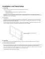
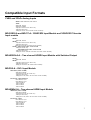
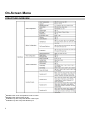
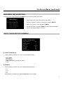
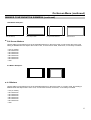
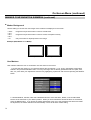
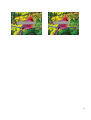
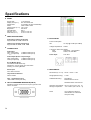
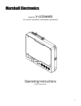
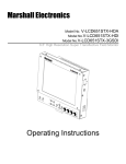
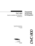
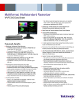
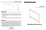
Marshall Electronics
V-MD171X
17” High Resolution Rack Mountable Monitor
Operating Instructions
Contents
Installation and Initial Setup ..............................................................................................................3
Front Panel Features ..........................................................................................................................4
Rear Panel Features ...........................................................................................................................5
Input Module Installation....................................................................................................................6
Compatible Input Formats..................................................................................................................7
On-Screen Menu .................................................................................................................................8
STRUCTURE OVERVIEW ................................................................................................................8
MAIN MENU AND NAVIGATION .....................................................................................................9
VIDEO CONFIGURATION SUBMENU .............................................................................................9
MARKER CONFIGURATION SUBMENU ...................................................................................... 12
FILTER CONFIGURATION SUBMENU.......................................................................................... 16
SYSTEM CONFIGURATION SUBMENU ....................................................................................... 17
FUNCTION PRESETS SUBMENU ................................................................................................. 19
Specifications.................................................................................................................................... 20
Dimensions........................................................................................................................................ 21
Maintenance ...................................................................................................................................... 22
Warranty ............................................................................................................................................ 22
2
Installation and Initial Setup
■ Unpacking
Carefully unpack the monitor and verify that the following items are included:
• MD-171 Monitor
• V-PS12-5V-XLR Power Supply with 4-Pin Male XLR Connector
• Operating Instructions
Inspect the unit for any physical damage that may have occurred during shipping. Should there be any damage,
immediately call Marshall Electronics Customer Service at (800) 800-6608. If you are not located within the continental
United States, call +1 (310) 333-0606.
■ Installation
The V-MD171X can be mounted in any standard EIA 19” equipment rack. The attached rack ears can be angled to
provide the user control over the viewing angle. Adequate ventilation is required when installed to prevent possible
damage to the monitor’s internal components.
A VESA standard 75mm hole pattern also allows custom mounting installations. Alternately, the V-MD171X can be
used in a desktop configuration with optional stand (Marshall part number V-ST15).
V-MD171X with optional desktop stand (Marshall
Part Number V-ST15)
■ Input Slots
Install any optional input modules BEFORE applying power to unit. Please see detailed instructions on Page 9.
■ Connections and Power-On
Plug the V-PS12-5V-XLR power supply into an AC power source (100-240 V @ 50/60 Hz). Attach the 4-pin male twistlock connector to the back of the monitor. The monitor draws a maximum of 3.0 Amps at 12 Volts in operation.
Connect the required cables for video signals, tally, etc. (Power must be applied to the V-MD171X for any of the active
loop-through outputs to be activated.) All BNC connectors are rated at 75Ω.
The unit defaults to ‘ON’ when power is supplied.
3
Front Panel Features
Power Button
Use the power button to toggle between ON and
STANDBY modes. In both the STANDBY and the
ON state, the LED on the button will illuminate bright
green. This indicates that MAINS power is applied to
the unit.
Input Select Buttons
Use the VIDEO, YPbPr, and S1/S2 buttons to select
the corresponding analog or digital input. Video
standards (NTSC/PAL, etc.) are automatically
detected. S1/S2 select inputs connected to Optional
Input Modules (located in Slot-1 or Slot-2).
User-Definable Function Buttons
Four user-definable function buttons can be used for
direct access to various settings. Functions are
assigned using the on-screen menu (Function
Presets – Page 21).
Menu Navigation Buttons
Use the Menu, ▲, ▼, and Select buttons to display
and navigate the on-screen menu (See Main Menu
and Navigation – Page 12).
4
Image Adjustment Knobs
Use the image adjustment knobs to adjust color
brightness, color-saturation, tint, and contrast of the
image. The status of each image adjustment
parameter is shown on the bottom left of the screen,
with values ranging from 0 to 100. Default value is
50.
LED Tally
Three LED tally lights (yellow, red, green) are
available above the screen. Each tally light can be
controlled independently from the rear Tally
Connector. (See Tally Hardware Interface, Page
22.)
Rear Panel Features
Component and Composite Input and Output
The V-MD171X has HD/SD component (YPbPr) and
composite analog input. There is as an active loopthrough output for each analog input. See page 10
for supported video formats. The BNC inputs are
internally terminated with 75 ohms. Outputs are
active ONLY when power is supplied to unit.
Programming Connector CN1*
For Factory Use ONLY.
*NOTE* although this appears to be a standard USB
connector, It is NOT. Do not connect to any
computer directly.
Power Input
Connect 12VDC to the 4-pin XLR power input
connector. Power should only be supplied from the
included power supply.
Desktop Mounting Holes
These holes are used when attaching the monitor to
the optional desktop stand.
See page 5 for details
IMPORTANT: If using a power source other than the
included power supply, damage may result. Please
use the pin out diagram in the Specifications section
of these Operating Instructions.
VESA 75mm Hole Pattern
VESA-standard 75 mm hole-pattern is provided to
accommodate a variety of custom mounting options.
Tally Input Connector (HD-15)
The LED tally can be activated via the HD-15
connector by connecting the corresponding pin to
ground. A variety of external devices can be used to
perform the contact closure. No additional power
should be supplied to the HD-15 port. See pin-out
details on page 22.
Input Slots, S1 and S2
The V-MD171X has 2 slots for optional input
modules. These modules allow for a wide variety of
input types and configurations. Modules are COLD
swappable and must only be inserted or removed
ONLY when Main Power is UPGLUGGED.
5
Input Module Installation
1. Remove Power From Unit
Modules are cold-swappable only. Damage will occur if modules are inserted or removed while unit is
powered.
2. Remove Blank Module Cover
Using Philips screwdriver, remove the 4-40x1/8” screws. There are a total of three screws, save them for
later use.
Remove blank cover
3. Insert Optional Module
Decide which slot you intend to install module (Slot 1 or Slot 2)
Carefully align the module with the chosen slot. The raised rails will fit inside the module
Align the Module so that the three (3) mounting holes all line up with the threaded holes of the slot.
The connectors on both the module and the main-board slot should now be in alignment.
Carefully PRESS the module into the slot. Module will seat flush with the rear of the unit.
Replace the three (3) screws removed in Step 2.
*NOTE* Use ONLY 4-40x1/8” screws provided. Any screw longer than 1/8” will damage the main unit.
6
Compatible Input Formats
CVBS and YPbPr Analog Inputs
VIDEO : NTSC 480i 59.94, PAL 525i 50
YPbPr:
480i 59.94, 576i 50
480p59.94, 576p50
720p (60 / 59.94 / 50 / 30 / 29.97 / 25)
1080i (60 / 59.94 / 50)
1080p (30 / 29.97 / 25 / 24 / 24sF / 23.98 / 23.98 sF)
MD-3GSDI-A and MD-TC-A– 3G/HD/SDI Input Module and 3G/HD/SDI Telecube
Input module
SD-SDI –
480i 59.94, 576i 50
HD-SDI –
720p (60 / 59.94 / 50 / 30 / 29.97 / 25)
1080i (60 / 59.94 / 50)
1080p (30 / 29.97/ 25 / 24 / 24sF/ 23.98 / 23.98sF)
3G-SDI – YCbCr (4:2:2) 10 Bit – Level A and B
1080p (60 / 59.94 / 50)
YCbCr/RGB (4:4:4) 10 Bit – Level A and B
1080i (60 / 59.94 / 50)
1080p (30 / 29.97 / 29.97sF / 25 / 25sF / 24 / 24sF / 23.98 / 23.98sF)
MD-HDSDIx2-A – Two-channel HDSDI Input Module with Switched Output
SD-SDI –
480i 59.94, 576i 50
HD-SDI –
720p (60 / 59.94 / 50 / 30 / 29.97 / 25)
1080i (60 / 59.94 / 50)
1080p (30 / 29.97/ 25 / 24 / 24sF/ 23.98 / 23.98sF)
MD-DVII-A – DVI-I Input Module
DVI-D Video (YCbCr or RGB)
480p 59.94, 576p50
720 (59.94 / 60 / 50 / 25 / 29.97 / 30 )
1080i (50 / 59.94 / 60)
1080p (23.97 / 24,/ 29.97 / 30 / 24 / 24sF / 23.98 / 23.98sF)
PC Formats – DVI-D and DVI-A
640 x 480 60, 72, 75
800 x 600 60, 72, 75
1024 x 768 60 70
1280 x 1024 60
1600 x 1200 60
1920 x 1200 60
MD-HDMIx2-A – Two-channel HDMI Input Module
HDMI Video (YCbCr or RGB)
480p 59.94, 576p50
720 (59.94 / 60 / 50 / 25 / 29.97 / 30 )
1080i (50 / 59.94 / 60)
1080p (23.97 / 24,/ 29.97 / 30 / 24 / 24sF / 23.98 / 23.98sF)
PC Formats – DVI-D
640 x 480 60, 72, 75
800 x 600 60, 72, 75
1024 x 768 60 70
1280 x 1024 60
1600 x 1200 60
1920 x 1200 60
7
On-Screen Menu
STRUCTURE OVERVIEW
1
Disabled when Color Temperature is set to Linear
Disabled when Pixel to Pixel is ON
3
Available only with Composite NTSC or PAL Input
4
Available only with Composite NTSC Input
2
8
On-Screen Menu (continued)
MAIN MENU AND NAVIGATION
Access the main menu by pushing the MENU button on the front panel of the monitor.
•
Step through menu items using the ▲ and ▼ buttons.
•
Choose a submenu or select a menu item by pressing SELECT.
•
Return to the previous menu by pressing MENU.
•
Exit the main menu by pressing MENU. The menu will automatically
time out after approximately 15 seconds.
Main Menu
VIDEO CONFIGURATION SUBMENU
Video Configuration Submenu
■ Color Temperature
Use this setting to choose one of five color temperature presets:
•
•
•
•
•
D65 (5500K)
D55 (6500K)
D93 (9300K)
USER (Adjustable Color Bias and Gain)
Linear
■ Gamma
Use this setting to choose one of four selectable Gamma tables:
• 2.2
• 2.4
• 1.8
• 2.0
Note: Gamma is disabled when Color Temperature is set to Linear
9
On-Screen Menu (continued)
■ RGB Bias and Gain
Select this submenu to fine-tune the monitor’s color balance (R, G, B). This should only be done by someone
experienced with video engineering, as this will alter the overall color shading of the screen. The purpose is to allow
color matching to other types of monitors and/or displays. Note: The Color Temperature preset will automatically
switch to USER when Color Bias settings are adjusted. It is normal for color bias adjustments to be very subtle.
When selecting the RGB Bias and Gain submenu, gain adjustment indicators will appear at the top of the screen, and
bias adjustment indicators will appear at the bottom of the screen:
RED
GREEN
BLUE
ALL
RGB Bias and Gain Submenu
Use the ▲ and ▼ buttons to select each individual bias or gain control. Press SELECT to begin adjusting the control. Use
the ▲ and ▼ buttons to increase or decrease the value.
Alternately, the image adjustment knobs (Brightness, Color, Tint, Contrast) can be used to easily adjust the bias and gain
settings as shown below. The knobs affect whichever row of controls (gain or bias) is currently selected.
Note: RGB Gain and Bias is disabled when Color Temperature is set to Linear.
■ Check Field
Use the check field modes for monitor calibration or to analyze individual color components of an image. In
Monochrome mode, all color is disabled and only a grayscale image is shown. In Blue, Green, and Red check field
modes, only the selected color will be shown.
■ Ratio (Aspect Ratio Settings)
Use to switch between Full Screen, 4:3 and 16:9 aspect ratios.
As the V-MD171X monitor has a native resolution of 1920 x 1200 RGB pixels, incoming images are automatically
scaled to fit the screen:
10
•
In Full Screen, images are scaled to fill the entire screen.
•
In 4:3 mode, images are scaled to fill the maximum 4:3 portion of the screen, with black bars filling the remainder
of the screen edges.
•
In 16:9 mode, images are scaled to fill the maximum 16:9 portion of the screen (1920 x1080), with black bars
filling the remainder of the screen.
On-Screen Menu (continued)
Full Screen
4:3 Mode
16:9 Mode
Note: The aspect ratio setting is ignored when Pixel-to-Pixel mode is ON.
■ Pixel-to-Pixel Mode
Use this setting to enable Pixel-to-Pixel mode.
This mode bypasses the monitor’s internal scaling function and displays incoming images in their native resolution and
aspect ratio, with a one-to-one mapping:
•
For incoming formats smaller than the native resolution of the LCD panel (1920 x 1200), the image will be
displayed in the center of the screen using only the necessary LCD pixels. For example, NTSC images will
occupy exactly 720 x 480 pixels. The surrounding pixels will be black.
Note: Pixel-to-Pixel mode disables aspect ratio control and H/V Delay.
■ H/V Delay
Use this setting to enable one of three delay modes (H & V Delay, V Delay, H Delay):
•
In H & V Delay mode, both horizontal sync and vertical sync are delayed, resulting in both horizontal and vertical
blanking periods being shown on the screen.
•
In V Delay mode, vertical sync is delayed so that the vertical blanking period is displayed on screen.
•
In H Delay mode, horizontal sync is delayed so that the horizontal blanking period is displayed on the screen.
Notes: H/V Delay is disabled when Pixel-to-Pixel mode is ON.
H/V Delay is only available with Composite inputs (NTSC or PAL)
■ Underscan
Use this setting to enable or disable Underscan mode:
•
When Underscan is OFF, the active portion of the video signal is displayed on the screen, with 0% overscan.
•
When Underscan is ON, the image size is slightly reduced. This allows the user to clearly view the edges of the
active video area.
Note: Underscan is only available with Composite inputs (NTSC or PAL)
11
On-Screen Menu (continued)
■ NTSC Black Level
Set the NTSC Black Level according to the type of NTSC composite video input:
•
7.5 IRE: Use this setting for standard NTSC-M signals which use a 7.5 IRE setup (black level).
•
0 IRE: Use this setting for NTSC-J signals which have no setup, or a black level of 0 IRE.
Note: This setting is disabled for PAL composite input and all component/3G-SDI formats.
MARKER CONFIGURATION SUBMENU
Marker Configuration Submenu
■ Markers
Use this setting to enable or disable all on-screen markers. This setting affects the center marker, full screen markers,
16:9 markers, and 4:3 markers.
■ Center Marker
Use this setting to display a center marker on the screen.
■ 16:9 Markers
Use these settings to superimpose one of the selectable markers on the screen when in 16:9 ratio mode.
•
•
•
•
•
•
•
•
•
•
•
•
•
12
Off (no marker)
4:3
13:9
14:9
1.85:1
2.35:1
95% Safe
93% Safe
90%Safe
88% Safe
85% Safe
80% Safe
User
On-Screen Menu (continued)
MARKER CONFIGURATION SUBMENU (continued)
16:9 Marker Examples:
OFF (No Marker)
2.35:1 Aspect Ratio
4:3 Aspect Ratio Markers
90% Safe Area
■ Full Screen Markers
Use this setting to superimpose one of the selectable markers on the screen when in Full Screen ratio mode. This
setting is disabled when the aspect ratio is set to 16:9, or when Pixel-to-Pixel, Underscan, or H/V Delay is enabled.
•
•
•
•
•
•
•
•
Off (no marker)
95% Safe Area
93% Safe Area
90% Safe Area
88% Safe Area
85% Safe Area
80% Safe Area
User
4:3 Marker Examples:
OFF (No Marker)
90% Safe Area
■ 4:3 Markers
Use this setting to superimpose one of the selectable markers on the screen when in 4:3 ratio mode. This setting is
disabled when the aspect ratio is set to 16:9, or when Pixel-to-Pixel, Underscan, or H/V Delay is enabled.
•
•
•
•
•
•
•
•
Off (no marker)
95% Safe Area
93% Safe Area
90% Safe Area
88% Safe Area
85% Safe Area
80% Safe Area
User
13
On-Screen Menu (continued)
MARKER CONFIGURATION SUBMENU (continued)
■ Marker Background
Use this setting to choose how outer edges of the markers are displayed on the screen:
•
•
•
•
•
100%
75%
50%
25%
0%
Image area beyond the marker is shown at solid black
Image area beyond the marker is shown at 50% Transparent overlay
Only The marker is superimposed on the image.
Example (80% Marker in 4:3 Mode):
Normal Background
Black Background
User Markers
User markers enable the user to create their own safe areas on the screen.
1. Choose the User option for your selected aspect ratio (Full Screen, 4:3 or 16:9) in the Marker Configuration
submenu and press the SELECT button. You may also begin with an already predefined safe area (95%, 93%,
90%, etc.) and make your adjustments from there by highlighting a particular safe area and pressing the SELECT
button.
2. Use the BRIGHT, COLOR, TINT and CONTRAST knobs to move the LEFT, RIGHT, TOP and BOTTOM
borders of the safe area to your desired position. When you have reached the desired location for the borders,
press the MENU button. If you began the marker adjustment using one of the predefined safe areas and made
an adjustment, the marker selection will automatically convert to the User marker setting.
14
15
On-Screen Menu (continued)
FILTER CONFIGURATION SUBMENU
■ False Colors
This monitor has a false color filter to aid in the setting of camera exposure. As the camera Iris is adjusted, elements of
the image will change color based on the luminance or brightness values. This enables proper exposure to be
achieved without the use of costly, complicated external equipment. To best utilize this feature, you must understand
the color chart below and have a basic understanding of camera exposure. Normally, when shooting subjects like
people, it is common practice to set exposure of faces to the equivalent of approximately 56 IRE. The false color filter
will show this area as the color PINK on the monitor. Therefore, as you increase exposure (open the IRIS), your
subject will change color as indicated on the chart: PINK, then GREY, then a few shades of YELLOW. Over exposed
subjects (above 101 IRE) on the monitor will be shown as RED. In addition, underexposed subjects will show as
DEEP-BLUE to DARK–BLUE, with clipped-blacks indicated with a FUCHSIA-like color. Lastly, the color GREEN is
used to indicate elements of the image that are approximately 45 IRE. This represents a ‘neutral’ or ‘mid-level’
exposure commonly used for objects (not people).
False Color Key
16
On-Screen Menu (continued)
FILTER CONFIGURATION SUBMENU (continued)
■ Mosquito Filter
Use this setting to filter out “Mosquito Noise” – an artifact that appears as specs around edges of objects. This artifact
is the result of video that has been compressed at some point. Video sources from DVD-Players, PDA’s, Digital Cable
Boxes, Camcorders, etc. often have this artifact.
SYSTEM CONFIGURATION SUBMENU
System Configuration Submenu
■ Input Format OSD
Use this option to enable on-screen display of input/format status in the upper-left corner of the screen. Options are:
Off, On or 5 Sec. When 5 Sec selected, On Screen display whenever a new input is received, then after approximately 5
seconds, the text wit disappear.
■ Curtain Color
Selects the color of the screen whenever there is no input, or if input is lost. Choices are: Blue, Black or Green.
■ Splash Screen
The Splash Screen is what is displayed when the monitor is first powered. The text “Marshall Electronics” is displayed
along with the model name of the unit. This feature can be turned off.
17
On-Screen Menu (continued)
SYSTEM CONFIGURATION SUBMENU (continued)
■ Freeze Input
Use the Freeze function to “freeze” the current image on the screen. Select this menu item again (Off) to return to the
real-time video input.
■ Load Setup
Up to 6 User Setups can be stored on this monitor. Load Setup allows instant recall of any of the 6 saved
configurations (User 1-6). Also available is the ability to load factory default settings. (MFG Default)
■ Save Setup
Up to 6 User Setups can be stored on this monitor. Save Setup allows the current configuration to be saved in one of 6
named locations in memory. (User 1-6). Settings are saved even if power is lost from the unit.
■ Power on Preset
Selects what preset configuration is loaded each time the monitor is powered. Choices are: Off – (last used
configuration), User 1-6, or MFG Default.
18
On-Screen Menu (continued)
FUNCTION PRESETS SUBMENU
■ Function Presets
Allows user to assign menu items to the front panel function buttons: F1, F2, F3 and F4. The following options are
available for each button:
•
•
•
•
•
•
Ratio
Check Field
Mosquito Filter
False Colors
Freeze Input
Aspect Markers
•
•
•
•
•
Center Marker
Markers
Underscan
H/V Delay
Pixel-to-Pixel
19
Specifications
■ PANEL
Screen Size
Display Area (h x v)
Aspect Ratio
Pixels
Viewing Angle (h x v)
Brightness
Contrast Ratio
Dot Pitch (h x v)
Pixel Pitch (h x v)
17.0” Diagonal
367.20 x 229.50 mm
16:10 Native (4:3/16:9 Selectable)
1920 x RGB x 1200
140° x 120°
2
330 cd/m
500:1
0.064 x 0.191 mm
0.191 x 0.191 mm
■ VIDEO INPUT/OUTPUT
Video Input / Output (Composite)
Supports SMPTE 170M, NTSC/PAL
YPBPR Input / Output (Component)
Supports SMPTE 260M, 274M, 296M
■ CONNECTORS
Video Input
Video (Composite)
YPBPR (Component)
1 x BNC Female (75 Ω)
3 x BNC Female (75 Ω)
■ ELECTRICAL
Power Consumption
ON:
3.5 Amp @ 12VDC (42 W Max)
Voltage Requirement
12VDC
V-PS12-5V-XLR Power Supply:
Input
100V-240V, 1.5A, 50-60Hz
Output
12VDC, 5A, 60W Max
Power Input
4-Pin XLR
Video Output (Active Loop-Through)
Video (Composite)
1 x BNC Female (75 Ω)
YPBPR (Component)
3 x BNC Female (75 Ω)
S1, S2 (Module Slots)
For Marshall I/O Modules Only
Cold-Swap – remove power from unit before
Inserting or removing Modules.
Power Input
4-Pin XLR Connector
■ MECHANICAL
Dimensions (w x h x d): 18.84” x 10.45” x 1.00”
Tally Hardware Interface
HD-15 Female
CN-1 – Programming Port*
* NOT USB – Factory Use Only
Weight (Monitor Only):
7.5 lbs
Additional Mounting:
Desk Stand
Marshall Part # V-ST15
Standard VESA 75mm Mount
■ TALLY HARDWARE INTERFACE (HD-15)
Activation requires contact closure of pin to ground on the
HD-15 connector:
Operating Temperature 32° F to 104° F (0° C to 40° C)
Storage Temperature
-4° F to120° F (-20° C to 50° C)
RoHs
20
Do not dispose. Return to
Manufacturer or Authorized
Recycle Facility.
Dimensions
21
Maintenance
■ Screen Cleaning
Periodically clean the screen surface using ammonia-free cleaning wipes (Marshall Part No. V-HWP-K). A clean microfiber cloth can also be used using only non-abrasive and ammonia-free cleaning agents. Do not use paper towels.
Paper towel fibers are coarse and may scratch the surface of the panel or leave streaks on the surface. Antistatic and
fingerprint resistant cleaning agents are recommended. Do not apply excessive pressure to the screen to avoid
damaging the LCD.
Warranty
Marshall Electronics warranties to the first consumer that this V-MD171X LCD monitor will, under normal use, be free from
defects in workmanship and materials, when received in its original container, for a period of one year from the purchase
date. This warranty is extended to the first consumer only, and proof of purchase is necessary to honor the warranty. If
there is no proof of purchase provided with a warranty claim, Marshall Electronics reserves the right not to honor the
warranty set forth above. Therefore, labor and parts may be charged to the consumer. This warranty does not apply to the
product exterior or cosmetics. Misuse, abnormal handling, alterations or modifications in design or construction void this
warranty. It is considered normal for a minimal amount of pixels, not to exceed three, to fail on the periphery of the display
active viewing area. Marshall Electronics reserves the option to refuse service for display pixel failure if deemed
unobtrusive to effective use of the monitor by our technicians. No sales personnel of the seller or any other person is
authorized to make any warranties other than those described above, or to extend the duration of any warranties on
behalf of Marshall Electronics, beyond the time period described above. Due to constant effort to improve products and
product features, specifications may change without notice.
Marshall Electronics, Inc.
1910 East Maple Ave.
El Segundo, CA 90245
Tel: (800) 800-6608 / (310) 333-0606 • Fax: 310-333-0688
www.LCDRacks.com • [email protected]
V2
22