1
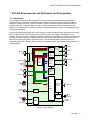
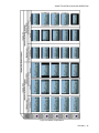
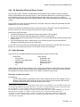
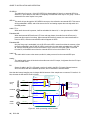
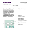
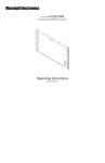
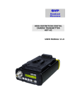
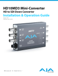
DVC-800
Guide to Installation and Operation
Downconverter
and DV Encoder
for HD Acquisition
M619-9900-100
Miranda
Technologies inc.
3499 Douglas-B.-Floreani
St-Laurent, Québec, Canada H4S 1Y6
Tel. 514-333-1772
Fax. 514-333-9828
www.miranda.com
DVC-800
Copyright 2003 Miranda Technologies Inc.
Specifications may be subject to change.
Printed in Canada
March 2003
GUIDE TO INSTALLATION AND OPERATION
Warranty Policies
Warranty Statement
Miranda Technologies Inc. warrants that the equipment it manufactures shall be free from defects in material and workmanship
for a period of two (2) years from the date of shipment from the factory. If equipment fails due to such defects, Miranda
Technologies Inc. will, at its option, repair or provide a replacement for the defective part or product. Equipment that fails after
the warranty period, has been operated or installed in a manner other than that specified by Miranda, or has been subjected to
abuse or modification, will be repaired for time and material charges at the Buyer’s expense.
All out-of-warranty repairs are warranted for a period of ninety (90) days from the date of shipment from the factory.
Miranda Technologies Inc. makes no other warranties, expressed or implied, of merchantability, fitness for a particular purpose
or otherwise. Miranda’s liability for any cause, including breach of contract, breach of warranty, or negligence, with respect to
products sold by it, is limited to repair or replacement by Miranda, at its sole discretion. In no event shall Miranda Technologies
Inc. be liable for any incidental or consequential damages, including loss of profits.
Effective January 1, 2002
Warranty Exchange Policies
Miranda Technologies Inc. warrants that the equipment it manufactures shall be free from defects in materials and workmanship
for a period of two (2) years from the date of shipment from the factory. If equipment fails due to such defects, Miranda will
provide repair of the failed unit under the terms of the Miranda warranty.
If the equipment has been proven to be defective on arrival, Miranda will ship a new product in exchange, usually within 36
hours of factory notification.
If the equipment to be repaired is essential and the customer so requests, Miranda will, at its option, provide a service
replacement or loaner part or product, usually within 36 hours of factory notification, weekends and holidays excluded.
All warranty exchange or loaner parts or products shall be shipped to the Buyer with a packing list clearly describing the items
and stating the date of shipment. Repaired parts or products will be shipped to the Buyer with a similar packing list. In the case
of exchange, the defective products or parts must be returned to Miranda within fifteen (15) days from receipt by the customer of
the exchange product. In the case of a loaner, the loaned products or parts must be returned to Miranda within fifteen (15) days
from receipt by the customer of the repaired equipment.
If the equipment is not returned within fifteen (15) days, as described for either exchanges or loans, A Rental Invoice will be
generated. Rental terms will be fifteen (15) percent of the current list price of the products or parts per month or a fraction
thereof. Before returning the equipment to Miranda Technologies Inc., for any reason, the Buyer must first obtain a Return
Authorization Number from Miranda Technologies Inc. Miranda Technologies Inc will pay freight and insurance charges for the
delivery of the loaner or exchange products or parts. Freight and insurance charges for the return of the defective product or
part will also be paid by Miranda Technologies.
Out-Of-Warranty Repair Policy
Miranda will service out-of-warranty repairs using the following model:
Miranda will charge 15% of the current list price of the product, with a minimum charge of $150. Products whose list price is
under $150 will be replaced at a charge equal to current list prices. In the case of obsolete products, the last published list price
for the products will apply. In the case of a product deemed beyond repair, the customer must purchase a new product at
current retail prices. All out-of-warranty repairs are warranted for a period of 90 days from the date of shipment from the factory.
Before returning the equipment to Miranda Technologies Inc., for any reason, the Buyer must first obtain a Return Authorization
Number
from Miranda Technologies Inc.
The Buyer will pay freight and insurance charges for the return of the defective product or part to the manufacturer for repair.
Miranda
Technologies will pay freight and insurance charges for the return of the repaired product or part to the Buyer.
Out-Of Warranty Equipment Updates and Spare Parts Policy
Miranda Technologies will charge cost plus 20% of the parts costs and $40.00 shipping and handling for out-of-warranty
equipment updates, or the sales of spare parts.
DVC-800 | i
GUIDE TO INSTALLATION AND OPERATION
Safety Compliance Information
Safety Compliance
This equipment complies with:
-
CAN/CSA C22.2 No. 950-95 / Safety of Information Technology Equipment, Including Electrical Business Equipment.
UL Std. No. 1950, 3rd Ed. / Safety of Information Technology Equipment, Including Electrical Business Equipment.
EN 60950:1992 (2nd edition) Incorporating A1, A2, A3, A4, and A11/ Safety of Information Technology Equipment,
Including Electrical Business Equipment.
CAUTION
These servicing instructions are for use by qualified service personnel only. To reduce the risk of electric shock, do not
perform any servicing other than that contained in the operating instructions unless you are qualified to do so. Refer all
servicing to qualified service personnel. Servicing should be done in a static-free environment.
Electromagnetic Compatibility
-
This equipment has been tested for verification of compliance with FCC Part 15, Subpart B, class A requirements for
Digital Devices.
This equipment complies with the requirements of:
EN 55022 Class A, Electromagnetic Emissions,
EN 61000-3-2 & -3-3, Disturbance in Supply Systems
EN 61000-4-2, -3, -4, -5, -6, -8 & -11 Electromagnetic Immunity
How to contact us:
Head Office
Miranda Europe
Miranda Asia
Miranda Technologies Inc.
3499 Douglas-B.-Floreani
St. Laurent (Montreal), Que. H4S 1Y6
Canada
222, 226 Rue De Rosny
93100 Montreuil
France
Mita Nexus Bldg. 2F
1-3-33 Mita, Minato-Ku
Tokyo, Japan 108-0073
Tel
Fax
Toll free:
+33 1 55 86 87 88
+33 1 55 86 00 29
+81 3 5730 2988
+81 3 5730 2973
+1 (514) 333-1772
+1 (514) 333-6914
1-800-224-9828
www.miranda.com
ii | DVC-800
GUIDE TO INSTALLATION AND OPERATION
Table of Contents
1 DVC-800 Downconverter and DV Encoder for HD Acquisition ................................. 1
1.1 Introduction .............................................................................................................................................. 1
1.2 Features ................................................................................................................................................... 2
2 Installation ..................................................................................................................... 4
2.1 Unpacking ................................................................................................................................................ 4
2.2 Mechanical Installation............................................................................................................................. 4
2.3 Electrical Installation ................................................................................................................................ 5
2.3.1 Camera and Battery connectors........................................................................................................ 5
2.3.2 Inputs and Outputs ............................................................................................................................ 5
2.3.3 Serial Communication Connector (RS-232) Layout .......................................................................... 6
2.3.4 Analog audio Connector Layout ........................................................................................................ 6
3 Configuration ................................................................................................................ 7
3.1 Large-scale production ............................................................................................................................ 7
3.2 Stand-alone Operation............................................................................................................................. 7
4 Operation ....................................................................................................................... 8
4.1 Powering Up............................................................................................................................................. 8
4.2 Local User Controls ................................................................................................................................. 8
4.2.1 POWER ............................................................................................................................................. 8
4.2.2 SAFETY ZONE.................................................................................................................................. 8
4.2.3 MARKERS......................................................................................................................................... 8
4.2.4 CENTER MARK ................................................................................................................................ 8
4.2.5 STATUS LEDS .................................................................................................................................. 8
4.2.6 Dip Switches...................................................................................................................................... 9
4.3 Supported HD Video Frame Rates .......................................................................................................... 9
4.4 Video Operation ..................................................................................................................................... 10
4.4.1 Video Source Selection ................................................................................................................... 10
4.4.2 Markers............................................................................................................................................ 10
4.4.3 Using the Aspect-Ratio Converter................................................................................................... 10
4.4.4 On-Screen Display (OSD) Configuration ........................................................................................ 12
4.4.5 Frame rate conversion from 23.98sF to 29.97 ................................................................................ 12
4.4.6 DV Operation & External Device Control ........................................................................................ 13
4.5 Audio Operation ..................................................................................................................................... 13
4.6 Time Code Operation............................................................................................................................. 15
4.6.1 Time Code source selection............................................................................................................ 15
4.6.2 User Bits .......................................................................................................................................... 16
4.7 Metadata and Telemetry ........................................................................................................................ 16
4.7.1 Telemetry Mode............................................................................................................................... 16
4.7.2 Control Mode ................................................................................................................................... 16
5 Specifications...............................................................................................................17
5.1 Input Specifications................................................................................................................................ 17
5.2 Output Specifications ............................................................................................................................. 17
5.3 Power Specifications.............................................................................................................................. 18
5.4 Processing Performance........................................................................................................................ 18
5.4.1 Video ............................................................................................................................................... 18
5.4.2 Audio ............................................................................................................................................... 18
5.4.3 Time Code ....................................................................................................................................... 19
DVC-800 | iii
GUIDE TO INSTALLATION AND OPERATION
iv | DVC-800
GUIDE TO INSTALLATION AND OPERATION
1 DVC-800 Downconverter and DV Encoder for HD Acquisition
1.1 Introduction
The DVC-800 is the latest in camera-adapted conversion devices from Miranda and was designed to
enhance electronic acquisition of material using HD cameras such as the SONY HDCAM (DVC-800) or
Panasonic Varicam (DVC-820). The DVC provides a unique combination of outputs and functionality to
facilitate monitoring, review and approval, rough cut editing and the preparation of dailies while on set.
Designed in cooperation with a number of electronic acquisition pioneers, the DVC is the indispensable tool
for electronic acquisition.
The SD video signal output allows the use of inexpensive monitors instead of costly high definition monitors.
The DVC-800 provides a built-in aspect-ratio converter allowing 16:9 images to be displayed on 4:3
monitors. The built-in 4:3 and 16:9 graticule generator allows on-screen display of aspect ratio markers. Also,
the OSD (On-Screen Display) unit allows information such as time code and scene numbers to be directly
seen on the screen on any down-converted outputs. The DVC-800 also does conversion from DV to
composite and SD SDI. The DVC-800’s low power consumption and miniature package make it ideal for onsite applications.
HD Cam
AES 2
AES 1
TC
HD SDI
IN
HD Digital //
Camera
Audio
HD SDI
Audio/TC
Mux +
// to Serial
HD SDI
10-bit
SD Cam
SD DV
AES 2
AES 1
TC
Down
Scaler
and
ARC
// HD
SD Cam
SD DV
AES 1 Ch-1/2
AES 2 Ch 3/4
Audio/TC
Mux +
// to Serial
SDI
10-bit
Composite
Encoder
+
D to A
Composite
Y
8-bit
Video
LTC
Cam TC
Audio TC
Graticule,
Burn In TC,
OSD
Audio TC
SD Play
SD Cam
Cam TC
Audio TC
AES 2
Ch 3/4
SD
TC In
AES In
DV
CODEC
Analog
Audio Out
DAC
DV from/to
IEEE-1394
Formatter
IEEE-1394
AES Out
uControler
DC IN
Belt
POWER
DC IN
Battery Pack
PDA Ctl,
GPI,
Telemetry
DC Out
To Camera
Figure 1 – Block Diagram
DVC-800 | 1
GUIDE TO INSTALLATION AND OPERATION
1.2 Features
Video Input
¾ One (1) HD SDI input
¾ Extraction of embedded audio group 1
¾ Extraction of ATC (video time code)
¾ One (1) SONY HDCAM Parallel video input with audio
¾ Channel 1/2 audio input from camera
¾ Channel 3/4 audio output to camera
¾ Pseudo-Automatic frame rate detection of HD video input
¾ Down-converted HD Formats:
1920x1080i/59.94
1920x1080p/29.97sF
1920x1080i/50
1920x1080p/25sF
1920x1080p/23.98sF 1280x720p/59.94
1280x720p/50
¾ Pass-through mode formats (to HD SDI out only)
1920x1080i/60
1920x1080p/30sF
1920x1080p/24sF 720p/60
¾ Automatic or Manual selection between HD SDI or HDCAM SONY video input
Video Output
¾ Two (2) HD SDI outputs including:
¾ Four (4) embedded audio channels
¾ ATC video time code (line 10)
¾ One (1) down-converted 10-bit SDI output including:
¾ 4 embedded audio channels
¾ DVITC (lines 14/16 and 277/279 in 525, lines 19/21 and 332/334 in 625)
¾ Graticule markers (selectable ON/OFF)
¾ Burned-in information such as time codes (Selectable ON/OFF)
¾ Down-converted 525/625 DV output via IEEE-1394 including:
¾ Two 16-bit audio channels (48KHz) selectable between channels 1/2 and 3/4
¾ Video and audio time codes
¾ Telemetry and metadata related to the scenes annotations
¾ Burned-in information such as time codes (Selectable ON/OFF)
¾ Down-converted composite (NTSC/PAL) and luminance (Y) output
¾ VITC insertion (lines 14/16 and 277/279 in 525, lines 19/21 and 332/334 in 625)
¾ Burned-in information such as time codes (Selectable ON/OFF)
¾ Graticule markers
¾ Aspect-ratio conversion allows:
¾ Display of 16:9 camera output on 4:3 (letterbox) or 16:9 monitors
¾ Predefined settings for resizing/cropping video in 4:3, 13:9, and 14:9 aspect ratio
¾ Selectable Graticule markers (for SD SDI, Composite/Y only):
¾ Safety zone markers for 4:3, 13:9, 14:9 selectable 50% transparent, line or opaque
¾ Safe title (80%), safe area (90%), 92.5%, 95%, 90% of 4:3
¾ One (1) user-programmable marker
¾ Two (2) types of center cross
General
¾ One RS-232 port, selectable for telemetry or control
¾ Analog audio output for monitoring channels 1/2 or 3/4
¾ Battery Pack style, attached directly to the camera
¾ Optimized power consumption - only the circuits in use are powered
¾ Auto Power Off
¾ DV power management
¾ DV sequence playback to SDI and Composite/Y
¾ Automatic detection of 525/625
2 | DVC-800
GUIDE TO INSTALLATION AND OPERATION
¾
¾
DV/DVCPRO1 compatible
Burned-in metadata information
Special
¾ Frame rate conversion from 23.98sF to 59.94i using conventional 3:2 pull-down sequence
¾ White line insertion (line 12) on Composite/Y and SDI output for flagging 1st frame of the
sequence
¾ Time code processing from 24f/s to 30f/s (non-drop frame only)
¾ External DV Device Control capabilities (AV/C protocol)
¾ Audio LTC input
¾ Replaces channel 4 of the embedded audio when present
¾ Can be inserted in DV as metadata
¾ Distinct graticule markers settings in DV playback mode and in normal mode
¾ Default configuration settings: for burned-in information and the user marker
1
Locked audio not supported for DVCPRO
DVC-800 | 3
GUIDE TO INSTALLATION AND OPERATION
2 Installation
2.1 Unpacking
Make sure the following items have been shipped with your DVC-800. If any of the following items are
missing, contact your distributor or Miranda Technologies Inc.
•
•
DVC-800 Downconverter and DV encoder for HD Acquisition
This manual
2.2 Mechanical Installation
The DVC-800 is installed at the rear of the camera body, positioned between the camera and the external
battery, and incorporates connectors and hardware which allow it to attach and connect to these two
components. The DVC-800 is designed to work with Sony HD cameras, and a variety of batteries, e.g. IDX,
Anton Bauer or PAG. These batteries have different mechanical interfaces, so it is necessary to specify the
battery type when ordering your DVC-800.
Figure 1.1 Mechanical installation of the DVC-800
To install the DVC-800 on the Sony HDCAM:
• remove the external battery or any other attachments on the rear of the camera body
• remove the small cap protecting the camera connector by removing the attaching screw.
• position the DVC-800, and push in and down until the HD CAM connector on the camera body mates
with the connector on the DVC-800
• tighten the two screw fasteners on the upper bracket to secure the DVC-800 in position
• Re-install the external battery or other attachment onto the rear of the DVC-800 case
4 | DVC-800
GUIDE TO INSTALLATION AND OPERATION
2.3 Electrical Installation
2.3.1 Camera and Battery connectors
The Sony HDCAM connector is integral to the mounting bracket, and connection is made when the DVC-800
is mounted on the rear of the camera body. As well, the external DC input is passed through the DVC-800.
2.3.2 Inputs and Outputs
All remaining input and output connectors are located on the side of the DVC-800 body. The figure shows
the location of the various connectors.
DIP switches
LTC in
HD SDI in
AUDIO LTC in
HD SDI out 1
COMPOSITE out
HD SDI out 2
Y out
SDI out
RS-232
ANALOG AUDIO out
External DC in
AES in
DV in/out (IEEE-1394)
Figure 1.2 Location of connectors on the DVC-800
DVC-800 | 5
GUIDE TO INSTALLATION AND OPERATION
2.3.3 Serial Communication Connector (RS-232) Layout
1
2
6
3
7
4
8
1 = NC
2 = (Rx) Receive (Input)
3 = (Tx) Transmit (output)
4 = 3.3VDC*
5 = Ground
6 = NC
7 = 3.3VDC*
8 = NC
9 = Force HD SDI input
5
9
* WARNING
The 3.3VDC pins should be used with caution.They
are meant to power external devices drawing less
than 2mA. Do not short to ground. Any misuse may
cause permanent damage to the unit
To force the HD SDI input at all times, short pin 9 to pin 5 (ground). See the discussion on video source
selection in Section 4.4.1
2.3.4 Analog audio Connector Layout
6
1
45
2
4
6 | DVC-800
3
1 = Ground
2 = Reserved
3 = Reserved
4 = Ground
5 = Audio Out Right
6 = Audio Out Left
GUIDE TO INSTALLATION AND OPERATION
3 Configuration
3.1 Large-scale production
The figure below illustrates a production configuration involving all of the inputs and outputs available on the
DVC-800. Observe how master recordings, dailies, on-set monitoring and off-line post-production capabilities
are all supported and facilitated through the use of the DVC-800. Subsets of this configuration may be
appropriate for less complex production situations.
Figure 3.1 DVC-800 at the center of a studio production
3.2 Stand-alone Operation
DV Drive
One useful application for the DVC-800
involves the use of a DV recorder
installed between the DVC-800 and the
battery, as shown in figure 3.2. This
recorder, supplied with DV video and time
code through the IEEE-1394 feed,
records a low-definition copy of the
master recording which is being recorded
on the camera’s HD cassette. This can
be used immediately for off-line post
production or dailies, eliminating the need
for dubbing after production is completed.
Figure 3.2 Stand-alone operation of the DVC-800
DVC-800 | 7
GUIDE TO INSTALLATION AND OPERATION
4 Operation
4.1 Powering Up
Use the Power button (section 4.2.1) to toggle between:
1. ON
(ON LED is lit)
2. AUTO OFF (both LEDs are lit) If there is no Input signal for more than 30 seconds, the unit will turn off
3. OFF
(both LEDs are off) The unit is OFF (Note: no power is consumed when the unit is OFF)
Use the dip switches HD OUT and SD OUT (see section 4.2.6) to control the power to the indicated output.
4.2 Local User Controls
The side panel incorporates 4 pushbuttons and 14 LEDs grouped into 5 sections (see fig.4.1):
4.2.1 POWER (discussion in section 4.1)
Pushbutton:
LEDs (2):
Power mode cycles through ON, AUTO OFF, and OFF
ON
Illuminated in ON and AUTO OFF modes
AUTO OFF Illuminated in AUTO OFF mode (turns unit OFF if there is no input
signal for more than 30 seconds)
4.2.2 SAFETY ZONE
Pushbutton:
Selects between OFF, 80%, 90%, 92.5%, 95%, 4:3
LEDs (4):
80%, 90%, 92.5%, 95%
(both 80% and 90% illuminate to indicate 4:3 mode)
4.2.3 MARKERS (discussion in section 4.4.2)
Pushbutton:
Selects between OFF, 4/3, 13/9, 14/9, FILM
LEDs (3):
4/3, 13/9, 14/9
(both 4:3 and 13:9 illuminate to indicate FILM mode)
4.2.4 CENTER MARK
Pushbutton:
Cycles between ON (normal cross), ON (small cross) and OFF
LED:
Illuminates when Centre Mark is turned ON (either size)
ON
Note: Two different sets of settings for the markers are stored in the DVC-800 - one for the
down-converter mode, and one for the DV playback mode. These settings are memorised
and retained when the unit is turned off.
4.2.5 STATUS LEDS
LEDs (4):
HD IN PRESENCE
GREEN: HD signal detected at the input
[POWER STATUS}
HD OUT
SD OUT
DV
8 | DVC-800
GREEN: HD-SDI output is active
GREEN: SD outputs (SDI and analog) are active
GREEN: A device is connected to the Firewire plug and powered on.
Figure 4.1
GUIDE TO INSTALLATION AND OPERATION
4.2.6 Dip Switches
There are 16 dip-switches located on the upper side panel of the DVC-800, laid out as shown in the figure
below.
OSD
24/30/60
i
LINE
BLACK
ON
ON
ON
ON
DISPLAY:
4/3
DEF. STD:525
FORMAT: DV
AUDIO: CAM
CTRL:
OFF
RS-232:
CTRL
HD OUT:
OFF
SD OUT:
OFF
DV
FR: 23.98/29.97/59.94
PsF
FORMAT:
MARKERS: MASK
50%
MASK:
SDI MARKERS:
OFF
SDI:
OFF
COMP/Y: OFF
OFF
DV:
16/9
625
DVCPRO25
AES
ON
TELEMETRY
ON
POWER
ON
MGNT
Figure 4.2 DIP-switch layout
The functionality of these switches is as follows:
FR (frame rate)
FORMAT
MARKERS
MASK
SDI MARKERS
OSD SDI
OSD COMP/Y
OSD DV
DISPLAY
DV DEF. STD
DV FORMAT
DV AUDIO
DV CTRL
RS232
POWER MGNT
HD OUT
SD OUT
Selects between 60/30/24 or 59.94/29.97/23.98 for HD standard detection
Selects between PsF or i for HD standard detection
Selects between Mask or Line for the markers (See section 4.4.2)
Selects between 50% transparent or Black. (See section 4.4.2)
Toggles the markers ON/OFF for the SD SDI output
Selects between ON or OFF for OSD on SDI output
Selects between ON or OFF for OSD on composite and Y output
Selects between ON or OFF for OSD on DV output
Selects between 4/3 or 16/9 monitors (See section 4.4.2)
Selects between 525 or 625 for DV default standard
Selects between DV or DVCPRO25 compression
Selects the audio to record in DV among the 4 available audio channels
CAM = Camera audio (either from HD SDI or form SONY connector)
AES = From the AES input
Enable/Disable the DV device control option (See section 4.4.6)
Selects between Telemetry or Control (See section 4.7)
(see section 4.1)
Selects between AUTO or OFF for power on the HD SDI output
Selects between AUTO or OFF for power on composite, Y and SDI outputs
4.3 Supported HD Video Frame Rates
NDF
DF
NDF
59.94i
DF
50i
NDF
30PsF
DF
NDF
29.97PsF
DF
25PsF
24PsF
23.98PsF -
CAMERA FORMAT
60i
SDI/DV/CVBS/Y
29.97Hz
n/a
n/a
OK
OK
n/a
n/a
n/a
OK
OK
n/a
n/a
3:2 Pull Down
Time Code
n/a
n/a
30 f/s NDF
30 f/s DF
n/a
n/a
n/a
30 f/s NDF
30 f/s DF
n/a
n/a
30 f/s NDF
DVC-800 OUTPUT
SDI/DV/CVBS/Y
25Hz
n/a
n/a
n/a
n/a
OK
n/a
n/a
n/a
n/a
OK
n/a
n/a
Time Code
n/a
n/a
n/a
n/a
25 f/s
n/a
n/a
n/a
n/a
25 f/s
n/a
n/a
HD SDI
60i
59.94i
50i
30PsF
29.97PsF
25PsF
24PsF
23.98PsF
Table 4.1 – Supported HD Video Frame Rates
DVC-800 | 9
GUIDE TO INSTALLATION AND OPERATION
4.4 Video Operation
4.4.1 Video Source Selection
If DV is input to the DVC-800 on the IEEE1394 connector, it is by default converted and sent to the SD video
outputs (composite,Y,SDI).
When there is no DV input to the DVC-800, the output is derived from one of the two HD inputs, selected
according to the following priorities:
- If a signal is present on the HDCAM connector, it is selected
- If no signal is present on the HDCAM connector, the HD SDI input is selected
- The user can short a pin on the RS-232 connector to force the HD SDI input to be selected (see section
2.3.3 for details)
The input video format is detected automatically within groups which are selected by the user using the
Frame Rate dip-switch and the i/PsF dip-switch. Here is a table of the supported formats and the state of
those switches for each case.
4.4.2 Markers
HD Format
1080i59.94
1080i50
720p50
720p59.94
1080p29.97sF
1080p23.98sF
1080p25sF
720p60
1080i60
1080p30sF
1080p24sF
Dip switch state
FR. RATE: 23/29/59
FORMAT:
PsF
24/30/60
i
FR. RATE: 23/29/59
FORMAT:
PsF
24/30/60
i
FR. RATE: 23/29/59
FORMAT:
PsF
24/30/60
i
FR. RATE: 23/29/59
FORMAT:
PsF
24/30/60
i
Table 4.2 dip-switch settings for video source selection
There exist multiple configurations for the markers. They are configured using the dip switches and the
buttons on the DVC-800 case. Figure 4.3 on the next page shows each configuration and its corresponding
dip switch position. Note that there is no black mask in 4:3 display mode. Instead the screen is scaled to fit
the selected aspect ratio. This mode activates the aspect-ratio converter (ARC).
The markers are always visible on the Composite/Y outputs. They can be set to ON or OFF on the SD SDI
output. They are never present on the DV output.
The FILM marker is use-programmable via software. The factory default is 1.85:1 aspect ratio.
4.4.3 Using the Aspect-Ratio Converter
The aspect-ratio converter (ARC) can be enabled only with 4:3 monitors. To activate the ARC:
Set the dip switch DISPLAY to the position 4/3
Set the dip switch MARKERS to the position Mask.
Set the dip switch MASK to the position Black.
Use the Markers button on the control panel to choose the aspect-ratio
The result is shown on the right-hand column of figure 4.3. The ARC affects all down-converted outputs.
10 | DVC-800
GUIDE TO INSTALLATION AND OPERATION
Figure 4.3 Marker configurations
DVC-800 | 11
GUIDE TO INSTALLATION AND OPERATION
4.4.4 On-Screen Display (OSD) Configuration
It is possible to display the following elements on the screen:
Main Title
Scene Description
Episode Number
Scene Number
Shot Number
Take Number
Reel Number
Director's name
Cameraman's name
Camera Number
Lens description
Location
Circled take
UMID 32 Bytes Binary
Producer's name
10 User-defined fields
HD TC Position
Rec Video TC Position
Rec Audio TC Position
HD Video Format
Start Time
Title TC Position
Recorded Date
The OSD screen can display 12 lines of 28 characters.
The user-defined fields allow the display of almost anything on the screen. The configuration of the OSD can
be accomplished using software available on Miranda’s web site. Software is available for both PC and PDA
platforms. For more information on how to configure the OSD, see section 4.7.2.
The OSD can be turned ON and OFF independently on the SDI, COMPOSITE/Y and DV outputs. Select the
desired status using the three OSD dip-switches.
4.4.5 Frame rate conversion from 23.98sF to 29.97
When 23.98sF HD formats are input to the DVC-800, a frame rate conversion is done automatically. The
process involves a conventional 3:2 pull-down sequence. The DVC-800 uses the video time code to
synchronize the sequence. The pull-down sequence, and the resulting frame correspondence over a period
of 1 second are shown in figure 4.4.
1080p23.98sF
:00
A1
525i
:01
A2
A1 A2
:00
B1
:02
B2
B1 B2
:01
C1
:03
C2
B1 C2
:02
D1
C1 D2
:03
D2
D1 D2
:04
1 second
24fps
30fps
:00
:01
:02
:03
:04
:05
:06
:07
:08
:09
:10
:11
:12
:13
:14
:15
:16
:17
:18
:19
:20
:21
:22
:23
:00 :01 :02 :03 :04 :05 :06 :07 :08 :09 :10 :11 :12 :13 :14 :15 :16 :17 :18 :19 :20 :21 :22 :23 :24 :25 :26 :27 :28 :29
Figure 4.4 Frame-rate conversion using 3:2 pull-down
12 | DVC-800
GUIDE TO INSTALLATION AND OPERATION
4.4.6 DV Operation & External Device Control
The DVC-800 is able to encode or decode DV25 and DVCPRO252 video formats in 525-line or 625-line
format (corresponding to the video input signal). In the normal state when there is no incoming DV stream,
the DVC-800 encodes a DV stream from the HD downconverted video input to the DV port. When an
external DV stream is detected, the DVC-800 decodes this video stream and displays it through the other SD
outputs.
The DVC-800 can control one external DV device3 (through the DV port) if it has VTR (video tape recorder)
capabilities (e.g. the AV/C protocol).
We don't recommend connecting more than one DV device (of the VTR type4) to the DVC-800 because, if
there is more than one, there is no way to select which one will be controlled.
Device control works as follows:
• The DVC-800 searches for an external DV device that supports VTR commands.
• If it finds one, it polls the VTR stable state (stop, pause/still or record pause)5.
• When a running timecode starts at the LTC input (LTC in), the DVC-800 sends a record command to the
external VTR.
• If the timecode stops or there is a discontinuity in the timecode sequence, the DVC-800 sends a
command corresponding to the previous stable state.
So, the user must set the VTR to the desired stable state before connecting it to the DVC-800, and ensure
that there is no running timecode at the LTC input when the device is connected.
4.5 Audio Operation
Figure 4.5 on the next page illustrates the audio processing functions of the DVC-800.
Audio Inputs:
- Sony camera
- HD SDI in (embedded audio)
- AES external
- Audio LTC in
- DV
Audio Outputs:
- Embedded in HD
- Embedded in SD
- Audio 3-4 to camera
- Analog audio out
- DV
Audio follows the same priorities as video; that is, if a DV input is present, it takes priority over the HD input,
and the audio from the DV input will appear on the analog and SD outputs. In the HD->DV mode, audio will
be embedded in this order of priority: Audio LTC in, AES in, HD SDI in or Sony audio.
Description of inputs and outputs :
HD CAM Sony:
The HD CAM connector is proprietary to Sony, and is located at the rear of their cameras. There is
always an audio signal, either voice, tone or mute. Audio 3 and 4 from the external AES IN of the
DVC-800 is always routed to the camera through this connector.
2
Locked audio is not supported for the DVCPRO25 format. This can be a problem for some DVCPRO VTRs that will
not accept the DVCPRO stream from the DVC-800. To be able to record the DVCPRO stream on a DVCPRO VTR,
the user might have to select a different audio source than the one included in the stream.
3
By "DV device" we mean a camcorder, a VTR, a firewire hard drive with device control capabilities (e.g. the AV/C
protocol) but not a computer. A computer is a general firewire device and not specifically a DV device.
4
A DV device of the VTR type can be a real VTR, a camcorder set in VTR mode, a hard drive with DV VTR
capabilities or a device of the DV-Bridge series (or any other DV transcoders with device control capabilities).
5
No other state is supported.
DVC-800 | 13
GUIDE TO INSTALLATION AND OPERATION
HD SDI IN:
The audio found in group 1 of the HD VIDEO IN is disembedded. If there is no external AES IN or
AUDIO LTC (time code) IN, this audio is completely reconstituted at the output. The group 1 audio is
extracted for the other outputs in any case..
AES IN:
This audio is input through the XLR AES IN connector, also referred to as external AES. This source
will be embedded in AES2, and will be sent to the DV and analog outputs when the dip switch is in
the AES position.
Audio LTC in:
When audio time code is present, it will be embedded in channel 4, i.e. the right channel of AES2.
Embedded HD:
When both external AES audio and LTC time code are absent, the audio from the HD source is
present at this output in its entirety. When external AES audio is present, the camera audio will be
found on AES1, while the external AES audio will appear in AES2.
Embedded SD:
Only the first group is embedded. In the HD->SD mode, AES1 comes from either the camera or from
the audio embedded in the HD SDI IN. AES 2 could come from the audio embedded in the HD SDI
IN, from the external AES IN or from the AUDIO LTC IN. In the DV->SD mode, AES1 is sourced
from the DV, while AES2 comes from the external AES IN or from the AUDIO LTC IN
Audio 3-4:
The audio which is sent to the camera, audio 3/4, always comes from the external AES input.
Analog:
The analog audio output is identical to the audio sent to the DV output; it originates from the DV input
in the DV->SD mode.
DV:
Source of audio in the DV-> SD mode, receiver of audio in the HD-> DV mode. Choose between
AES1 and AES2 with the CAM/AES dip-switch, where CAM=AES1 and AES=AES2.
Note that the internal sampling rate is always 48KHz because of the sample rate converters. DV audio is 16
bits, whereas the HD and SD audio is 24 bits.
While in playback use
the DV source.
DV_AES1
HD cam
Sony
Audio
Sony
Sony_AES1
1-2
AUDIO34
Emb_AES1
1-2
*
*
AES1
HD EMB.
IF DV-> SD no output HD
SD EMB.
HD SDI IN
Audio
Emb HD SDI
Emb_AES2
DV, analogue
3-4
3-4
AES IN
AES
externe
Aes externe
3-4
3
AES2
*
CAM (1-2) = AES1
AES (3-4) = AES2
4
AUDIO
LTC IN
Time code
audio
Audio LTC
4
*
4
4
Figure 4.5 Audio processing in the DVC-800
14 | DVC-800
Dip Switch
GUIDE TO INSTALLATION AND OPERATION
Audio Operation
Sony
1
CAM
√
√
√
√
HD
SDI
√
√
√
√
Video
Video
Video
Video
√
1
2
3
Input
AES
IN
AUDIO
LTC IN
DV
IN
√
√
√
√
√
√
√
√
√
√
√
√
√
√
√
√
√
√
Internal
AES1
AES2
Sony
Sony
Sony
DV
HD SDI
HD SDI
HD SDI
DV
------------DV
----AES in
AES+TC
----HD SDI
AES in
AES+TC
--------AES in
AES+TC
-----
EMB
HD
Aes1
Aes1+2
Aes1+2
----2
Audio
Aes1+2
Aes1+2
--------Aes2
Aes2
-----
EMB
SD
Aes1
Aes1+2
Aes1+2
Aes1
Aes1+2
Aes1+2
Aes1+2
Aes1
----Aes2
Aes2
Aes1
Output
Audio
3-4
----AES in
AES in
AES in
----AES in
AES in
AES in
----AES in
AES in
AES in
Analog & DV OUT
3
CAM
AES
Sony
----Sony
AES in
Sony
AES+TC
DV
DV
HD SDI
HD SDI
HD SDI
AES in
HD SDI AES+TC
DV
DV
------------AES in
----AES+TC
DV
DV
= Audio present
= There is always audio coming from the SONY HDCAM.
= Passthrough audio only
= Dip switch (audio DV)
4.6 Time Code Operation
The DVC-800 integrates many different time codes:
Title Time Code:
Video HD time code :
Video SD time code:
Audio time code:
In DV playback only. Time code generated by DV applications
Original time code synchronized with the HD video input
Processed time code synchronized with the SD video output
Audio time code sampled at SD frame rate
Any of these time codes can be displayed on the screen.
4.6.1 Time Code source selection
There are 3 possible sources of video time code and one source of audio time code:
Video time code sources:
Audio time code source:
External LTC, External from HD SDI input, Internally generated
External LTC only
Video time code source selection:
• When all time code sources are present, the LTC input has priority over the others. Therefore, the DVC800 will not read the time code embedded in the HD SDI input signal if an external LTC signal is present.
• When no time code source is present, the DVC-800 generates its own time code. This is necessary for
DV to work properly and also for the frame rate converter.
Audio time code source selection:
• If a signal is present at the Audio LTC input, the time code is extracted and re-sampled at the SD frame
rate. This is necessary since the audio LTC has to follow the video path.
• If no signal is present, no internal time code is generated and its value remains unchanged
In some cases, the time code is processed and compensated for delays. In other cases, no compensations
are required. See section 5.4.3 for time code processing performance.
DVC-800 | 15
GUIDE TO INSTALLATION AND OPERATION
4.6.2 User Bits
User bits are part of the time code. They are transported along with the time code. No modifications are
performed on them. In some cases, the user bits are delayed with respect to the picture. See section 5.4.3
for information on delays.
4.7 Metadata and Telemetry
Metadata (for the DVC-800) is data that carries information about the video image such as time, date, scene
number, etc. This data is directly inserted into the DV signal. It can be extracted from the resulting DV file
during post-production and used to select desired scenes. Metadata is a powerful tool for video editing.
The DVC-800 can insert and extract metadata is two different ways:
•
•
Telemetry Mode: Everything (every character) received via the asynchronous port (RS-232) is inserted
in metadata.
Control Mode: Use this mode to configure the OSD and at the same time the information that will be
inserted as metadata. This mode should be selected in order to use the configuring software.
The user can select the operating mode using the CTRL/TELEMETRY dip switch. In all cases, the
information to be inserted as metadata is sent via the RS-232 connector, and the DVC-800 must connected
to a PC or a PDA.
4.7.1 Telemetry Mode
In Telemetry Mode, all data arriving at the RS-232 port is packaged and inserted as metadata into the DV
signal. Miranda does not specify the data format, so this mode is suitable for third-party devices using
proprietary formats for specialized applications which involve the transfer of metadata into postproduction. As
an example, this mode could be used to transfer camera positioning and movement data for integrating
camera video into graphical environments.
4.7.2 Control Mode
In Control Mode, the RS-232 port is connected to a PC or PDA running software created by Miranda. This
software allows the user to perform two functions:
•
•
Specify the metadata which is to be included in the DV datastream. A list of standard items representing
the most-frequently used information is pre-defined, but there are also ten user-defined items which can
include any other data which is available.
Specify which of this metadata will be shown in the On Screen Display (OSD) and how and when it will
appear.
The functionality of this software is fully explained in its User Manual.
16 | DVC-800
GUIDE TO INSTALLATION AND OPERATION
5 Specifications
5.1 Input Specifications
HD SIGNAL
FORMAT
CONNECTOR
20-bit Y-Pb-Pr HD as per HDW-F900 Sony Interface
1920x1080i/59.94
SMPTE-274M
1920x1080i/60
SMPTE-274M
1920x1080p/30sF
SMPTE-274M
1920x1080p/29.97sF
SMPTE-274M
1920x1080i/50
SMPTE-274M
1920x1080p/25sF
SMPTE-295M
1920x1080p/24sF
SMPTE-274M
1920x1080p/23.98sF SMPTE-274M
1280x720p/59.94
SMPTE-296M
1280x720p/50
SMPTE-296M
1280x720p/60
SMPTE-296M
50-pin camera connector, as per Sony HDW-F900
HD SDI SIGNAL
RETURN LOSS
CONNECTOR
4:2:2 SMPTE 292M, SMPTE 299M
> 15 dB up to 1.5 GHz
75 Ω BNC
AUDIO CAM (1/2)
LEVEL:
CONNECTOR
per Sony HDW-F900
LVTTL, 3.3V
50-pin camera connector, as per Sony HDW-F900
AES2 (3/4) SIGNAL
LEVEL:
IMPEDANCE:
CONNECTOR
AES3
0.2 to 7.0 Vp-p
110 Ω balanced
XLR-3F
LTC SIGNAL
LEVEL:
CONNECTOR
SMPTE 12M
0.2 to 5 Vp-p
75 Ω BNC
5.2 Output Specifications
HD SDI SIGNAL
RETURN LOSS
JITTER
CONNECTOR
4:2:2 SMPTE 292M, SMPTE 299M
> 15 dB up to 1.5 GHz
< 0.2 UI p-p
75 Ω BNC
SDI SIGNAL
RETURN LOSS
JITTER
CONNECTOR
4:2:2 SMPTE 259M, SMPTE 272M
> 15 dB up to 270 MHz
< 0.2 UI p-p
75 Ω BNC
COMPOSITE SIGNAL
NTSC (525/60) SMPTE 170M
PAL (625/50) ITU RT 470
> 20 dB up to 5.75 MHz
< -58 dB to 5.75 MHz (unweighted)
75 Ω BNC
RETURN LOSS
SNR
CONNECTOR
DVC-800 | 17
GUIDE TO INSTALLATION AND OPERATION
Y SIGNAL
RETURN LOSS:
SNR
CONNECTOR:
Luminance only (525/60 or 625/50)
> 20 dB up to 5.75 MHz
< -58 dB to 5.75 MHz
75 Ω BNC
DV SIGNAL
CONNECTOR
DV/DVCPRO25 on IEEE-1394a
IEEE-1394 6 pin
AUDIO SIGNAL
LEVEL:
IMPEDANCE
SNR
CONNECTOR
Stereo unbalanced line out
1.0 Vp-p
< 600 Ω
< 70 dB Ref 0 dBFS (A weighted)
Mini XLR-5
AUDIO CAM (3/4)
LEVEL:
CONNECTOR
per Sony HDW-F900
LVTTL, 3.3V
50-pin camera connector, as per Sony HDW-F900
5.3 Power Specifications
POWER INPUT:
POWER CONNECTOR:
POWER:
TEMP. RANGE
11 – 17 VDC
XLR-4, and Battery connector “IDX” or “Anton Bauer” or “PAG”
10 Watts Max
0-40o C
5.4 Processing Performance
5.4.1 Video
SIGNAL PATH:
10-bit SD SDI,
8-bit COMPOSITE,
8-bit DV
PROCESSING DELAY:
DV:
COMPRESSION:
10-bit HD SDI,
HD input to HD SDI output: < 2uS
HD input to SD SDI and COMPOSITE outputs:
Frame rate of 59.94Hz = 34ms
Frame rate of 50Hz
= 41ms
Frame rate of 23.98Hz = 83ms
HD input to DV output: Same as for composite + 1.5 SD FRAME
DV input to SD SDI and COMPOSITE output: 1.5 SD FRAME
DV format at 25 Mbps as per DV Blue Book, and DVCPRO25
DV 4:1:1 in NTSC, 4:2:0 in PAL, DVCPRO25 4:1:1 in PAL
5.4.2 Audio
SIGNAL PATH:
PROCESSING DELAY:
18 | DVC-800
24-bit HD SDI,
20-bit SD SDI,
16-bit DV
AES to Analog out
Frame rate 59.94Hz = 34ms
Frame rate 50Hz
= 40ms
Frame rate 23.98Hz = 83ms
GUIDE TO INSTALLATION AND OPERATION
5.4.3 Time Code
SourceÆ Dest.
LTCÆ SD,DV
DVITC Æ SD,DV
DV Æ SD
LTC Æ HD DVITC
DVITC Æ HD DVITC
Time Code
1fr compensation
Transparent
1fr compensation
2fr compensation
Transparent
User Bits
1fr delay
Transparent
Transparent
1fr delay
Transparent
Transparent = Remains unprocessed, i.e. Out = In
Compensation = Time code is compensated for delays
Delay = The user bits will lag the video by 1 frame.
DVC-800 | 19