1
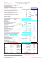
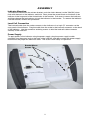
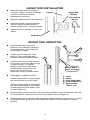
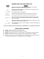
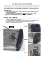
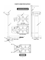
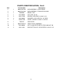
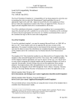
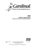
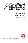
European Digital Scale
Waist-High Models
EU522/EU522HR
and
Floor Model EU544
Owner’s Manual
0049-M020-O1 Rev C
12/05
CARDINAL SCALE MFG. CO.
PO BOX 151 v WEBB CITY, MO 64870
PH (417) 673-4631 v FAX (417) 673-5001
www.detectoscale.com
1
Printed in USA
2
EUROPEAN DECLARATION OF CONFORMITY
Manufacturer:
Detecto Scale Company
Cardinal Scale Manufacturing Company
PO Box 151
203 East Daugherty
Webb City, Missouri 64870 USA
Telephone No. + 417 673 4631
Fax No.
+ 417 673 5001
Product:
Digital Waist-High Scale
Model Numbers EU522 / EU522HR / EU544
Serial Number EXXXYY-ZZZ
where XXX = day of year
YY = last two digits of year
ZZZ = sequential number
The undersigned hereby declares, on behalf of Detecto Scale Company and Cardinal Scale
Manufacturing Company of Webb City, Missouri, that the above-referenced product, to which this
declaration relates, is in conformity with the provisions of:
European Standard EN45501 and equivalent International
Recommendation OIML R76, edition 1992
Test Certificate Number: GB-1136
Council Directive 73/23/EEC (19 February, 1973) Low Voltage Directive as amended by
Council Directive 93/68/EEC (22 July, 1993)
Council Directive 90/384/EEC (20 June, 1990) on the Harmonization
Of the Laws of Member States relating to non-automatic weighing
Systems as amended by:
Council Directive 93/68/EEC (22 July, 1993)
Certificate of EU Type Approval Number: UK 2655
European Standard EN55024 for radiated emissions Class A
European Standard EN55024 for conducted disturbances Class A
Test Report Number: 020424-537
The Technical Construction File required by this Directive is maintained at the corporate
headquarters of Cardinal Scale Manufacturing Company, 203 East Daugherty, Webb City,
Missouri.
_____________________
Link Yeager
Quality Assurance Administrator
3
Attachment
to the Conformity document
DECLARATION OF CONFORMITY
with WELMEC 2 paragraph 12
Page 1 of 1
COMPATIBILITY OF MODULES
Ref.: WELMEC 2 (2000)
Non-Automatic Weighing Instrument, single-interval
o
Certificate of EU Type-Approval N :
TAC:
INDICATOR
A/D (Module 1)
Accuracy class according to EN 45501 and OIML R76:
Maximum number of verification scale intervals (nmax):
Fraction of maximum permissible error (mpe)
Load cell excitation voltage:
Minimum input-voltage per verification scale interval:
Minimum load cell impedance:
Coefficient of temperature of the span error:
Coefficient of resistance for the wires in the J-box cable:
Specific J-box cable-Length to the junction box for load cells
Load cell interface:
Additive tare, if available:
Initial zero setting range
Temperature range
Type:
758CSV
Classind ( I, II, III or IIII )
nind
p1
Uexc
[ Vdc ]
[ µV ]
∆umin
[ Ω]
RLmin
Es
[ % / 25°C ]
Sx
[ % / Ω]
(L/A)max
[ m / mm² ]
4-wire (no sense)
T+
[ % of Max ]
IZSR
[ % of Max ]
[ °C ]
Tmin / Tmax
NWML GB-1136
Test report (TR), Test Certificate (TC) or OIML Certificate of Conformity:
LOAD RECEPTOR
(Module 2)
Type:
Construction:
Fraction of mpe:
Number of load cells:
Reduction ratio of the load transmitting device:
Dead load of load receptor
Non uniform distribution of the load
Correction factor:
LOAD CELL
III
5000
0.5
5
1.2
87
0.006
0.0152
175
-2
-10
0
/
/
2
40
EU522 / EU522HR
Platform
p2
N
R=FM / FL
DL
(NUD = 0 is acceptable)
NUD
Q = 1 + (DL + T+ + IZSR + + NUD) / 100
ANALOG (Module 3)
Type:
TSSP-200KGW
COMPLETE WEIGHING INSTRUMENT
Manufacturer:
Detecto
Accuracy class according to EN 45501 and OIML R76:
Fractions: pi = p1² + p2² + p3²:
Maximum capacity:
Number of verification scale intervals:
Verification scale interval
Utilisation ratio of the load cell
Input voltage (from the load cels):
Cross-section of each wire in the J-box cable:
J-box cable-Length
Temperature range to be marked on the instrument
Peripheral Equipment subject to legal control
0.5
1
1
8.7
4
1.147
[ % of Max ]
[ % of Max ]
ClassLC ( A, B, C or D )
nLC
p3
C
[ mV / V ]
[ Ω]
RLC
vmin% [ % of Emax ]
Emax
[ kg ]
[%]
(Emin / Emax) * 100
[ °C ]
Tmin / Tmax
R60/2000-DK1-04.05
Accuracy class according to OIML R60:
Maximum number of load cell intervals:
Fraction of mpe:
Rated output (sensitivity):
Input resistance of single load cell:
Minimum load cell verification interval:
(vmin% = 100 / Y)
Rated capacity:
Minimum dead load, relative
Temperature range
Test report (TR) or Test Certificate (TC/OIML) as appropriate
ClassWI
pi
n
n
n
Emin
vmin * √N / R
UK2655
-10
C
3000
0.7
2
350
0.0125
230
0
/
40
Single-interval
Type:
EU522 / EU522HR
ClassWI ( I, II, III or IIII )
pi
Max
[ kg ]
n
e
[ kg ]
α = (Max / Emax) * (R / N)
∆u = C * Uexc * α * 1000 / n
[ µV/e ]
A
[ mm² ]
L
[m]
Not required
Tmin / Tmax
[ °C ]
Acceptance criteria for compatibility
<= Classind & ClassLC (WELMEC 2: 1)
<= 1
(R76: 3.5.4.1)
(R76: 3.2)
<= nmax for the class
(WELMEC 2: 4)
<= nind
(R76: 4.12.2)
<= nLC
<= DL * R / N
(WELMEC 2: 6d)
<= e
(R76: 4.12.3)
or (if vmin is not given)
(Emax / nLC) * (√N / R)
∆umin
RLmin
<=
<=
<=
e
∆u
RLC / N
(WELMEC 2: 7)
(WELMEC 2: 8)
(WELMEC 2: 9)
L/A
Trange
Q * Max * R / N
<=
<=
<=
(L / A)maxWI
Tmax - Tmin
Emax
(WELMEC 2: 10)
(R76: 3.9.2.2)
(R76: 4.12.1)
III
1.0
200
2000
0.1
0.87
4.35
0.5
3
Passed, provided no result below is < 0
ClassWI :
PASSED
1 - pi =
0.0
nmax for the class - n =
8000
nind - n =
3000
1000
nLC - n =
(DL * R / N) - Emin =
17.4
e - (vmin * √N / R) =
0.071
Alternative solutions:
↑ ↓
e - ((Emax / nLC) * (√N/ R)) =
∆u − ∆umin =
3.15
(RLC / N) - RLmin =
263
(L / A)maxWI - (L / A) =
(Tmax - Tmin) - Trange =
Emax - (Q * Max * R / N) =
Signature and date:
Conclusion . . . . .
607
20
0.6
PASSED
This is an authentic document made from the program:
"Compatibility of NAWI-modules version 3.0".
Program made by DELTA
Per Bengtsen, EU Notified Body No. 0199
Single-interval
EU522_Comp_of_Modules_200kg1.xls
Attachment
to the Conformity document
DECLARATION OF CONFORMITY
with WELMEC 2 paragraph 12
Page 1 of 1
COMPATIBILITY OF MODULES
Ref.: WELMEC 2 (2000)
Non-Automatic Weighing Instrument, single-interval
o
Certificate of EU Type-Approval N :
TAC:
INDICATOR
A/D (Module 1)
Accuracy class according to EN 45501 and OIML R76:
Maximum number of verification scale intervals (nmax):
Fraction of maximum permissible error (mpe)
Load cell excitation voltage:
Minimum input-voltage per verification scale interval:
Minimum load cell impedance:
Coefficient of temperature of the span error:
Coefficient of resistance for the wires in the J-box cable:
Specific J-box cable-Length to the junction box for load cells
Load cell interface:
Additive tare, if available:
Initial zero setting range
Temperature range
Type:
758CSV
Classind ( I, II, III or IIII )
nind
p1
Uexc
[ Vdc ]
[ µV ]
∆umin
[ Ω]
RLmin
Es
[ % / 25°C ]
Sx
[ % / Ω]
(L/A)max
[ m / mm² ]
4-wire (no sense)
T+
[ % of Max ]
IZSR
[ % of Max ]
[ °C ]
Tmin / Tmax
NWML GB-1136
Test report (TR), Test Certificate (TC) or OIML Certificate of Conformity:
LOAD RECEPTOR
(Module 2)
Type:
Construction:
Fraction of mpe:
Number of load cells:
Reduction ratio of the load transmitting device:
Dead load of load receptor
Non uniform distribution of the load
Correction factor:
LOAD CELL
III
5000
0.5
5
1.2
87
0.006
0.0152
175
-2
-10
0
/
/
2
40
EU544
Platform
p2
N
R=FM / FL
DL
(NUD = 0 is acceptable)
NUD
Q = 1 + (DL + T+ + IZSR + + NUD) / 100
ANALOG (Module 3)
Type:
TSSP-200KGW
COMPLETE WEIGHING INSTRUMENT
Manufacturer:
Detecto
Accuracy class according to EN 45501 and OIML R76:
Fractions: pi = p1² + p2² + p3²:
Maximum capacity:
Number of verification scale intervals:
Verification scale interval
Utilisation ratio of the load cell
Input voltage (from the load cels):
Cross-section of each wire in the J-box cable:
J-box cable-Length
Temperature range to be marked on the instrument
Peripheral Equipment subject to legal control
0.5
1
1
8.7
4
1.147
[ % of Max ]
[ % of Max ]
ClassLC ( A, B, C or D )
nLC
p3
C
[ mV / V ]
[ Ω]
RLC
vmin% [ % of Emax ]
Emax
[ kg ]
[%]
(Emin / Emax) * 100
[ °C ]
Tmin / Tmax
R60/2000-DK1-04.05
Accuracy class according to OIML R60:
Maximum number of load cell intervals:
Fraction of mpe:
Rated output (sensitivity):
Input resistance of single load cell:
Minimum load cell verification interval:
(vmin% = 100 / Y)
Rated capacity:
Minimum dead load, relative
Temperature range
Test report (TR) or Test Certificate (TC/OIML) as appropriate
ClassWI
pi
n
n
n
Emin
vmin * √N / R
UK2655
-10
C
3000
0.7
2
350
0.0125
230
0
/
40
Single-interval
Type:
EU544
ClassWI ( I, II, III or IIII )
pi
Max
[ kg ]
n
e
[ kg ]
α = (Max / Emax) * (R / N)
∆u = C * Uexc * α * 1000 / n
[ µV/e ]
A
[ mm² ]
L
[m]
Not required
Tmin / Tmax
[ °C ]
Acceptance criteria for compatibility
<= Classind & ClassLC (WELMEC 2: 1)
<= 1
(R76: 3.5.4.1)
(R76: 3.2)
<= nmax for the class
(WELMEC 2: 4)
<= nind
(R76: 4.12.2)
<= nLC
<= DL * R / N
(WELMEC 2: 6d)
<= e
(R76: 4.12.3)
or (if vmin is not given)
(Emax / nLC) * (√N / R)
∆umin
RLmin
<=
<=
<=
e
∆u
RLC / N
(WELMEC 2: 7)
(WELMEC 2: 8)
(WELMEC 2: 9)
L/A
Trange
Q * Max * R / N
<=
<=
<=
(L / A)maxWI
Tmax - Tmin
Emax
(WELMEC 2: 10)
(R76: 3.9.2.2)
(R76: 4.12.1)
III
1.0
200
2000
0.1
0.87
4.35
0.5
3
Passed, provided no result below is < 0
ClassWI :
PASSED
1 - pi =
0.0
nmax for the class - n =
8000
nind - n =
3000
1000
nLC - n =
(DL * R / N) - Emin =
17.4
e - (vmin * √N / R) =
0.071
Alternative solutions:
↑ ↓
e - ((Emax / nLC) * (√N/ R)) =
∆u − ∆umin =
3.15
(RLC / N) - RLmin =
263
(L / A)maxWI - (L / A) =
(Tmax - Tmin) - Trange =
Emax - (Q * Max * R / N) =
Signature and date:
Conclusion . . . . .
607
20
0.6
PASSED
This is an authentic document made from the program:
"Compatibility of NAWI-modules version 3.0".
Program made by DELTA
Per Bengtsen, EU Notified Body No. 0199
Single-interval
EU544_Comp_of_Modules_200kg.xls
This page intentionally left blank.
INTRODUCTION
Thank you for your purchase of our Detecto European Digital Scale, Waist-High Models
EU522 / EU522HR or Floor Model EU544. They were built with Detecto quality and reliability
at our factory in Webb City, Missouri, USA. This manual will guide you through installation,
and operation of your scale. Please read it thoroughly before attempting to operate this scale
and keep it handy for future reference.
All rights reserved. Reproduction or use, without expressed written permission, of editorial or pictorial content, in
any manner, is prohibited. No patent liability is assumed with respect to the use of the information contained
herein. While every precaution has been taken in the preparation of this manual, the Seller assumes no
responsibility for errors or omissions. Neither is any liability assumed for damages resulting from use of the
information contained herein. All instructions and diagrams have been checked for accuracy and ease of
application; however, success and safety in working with tools depend to a great extent upon the individual
accuracy, skill and caution. For this reason the Seller is not able to guarantee the result of any procedure
contained herein. Nor can they assume responsibility for any damage to property or injury to persons occasioned
from the procedures. Persons engaging the procedures do so entirely at their own risk.
SPECIFICATIONS
Capacity: ….…..……..…… 200 kg x .1 kg
Platform Size: …….…..….. 280 mm x 335 mm
Dimensions: ….…..………. EU522 = 280 mm W x 490 mm D x 888 mm H
EU544 = 280 mm W x 515 mm D x 210 mm H
Power Requirements: …… 230 VAC 50 Hz powering a 12 VDC 300 mA wall plug-in power
supply OR Six (6) "C" size NICAD batteries, (not included)
Operating Temp: ………… -10 to +40 oC
Shipping Weight: …..…..… 7.7 kg
PREPARATION
Unpacking Instructions
SCALE
v Remove scale from carton by lifting up with equal force from column and platform base of
scale.
v
When removing scale from its packing, inspect it for signs of damage, such as exterior
dents and scratches. Keep carton and packing material for return shipment if it should
become necessary.
v
Remove all plastic wrapping, foam fillers and cardboard material from scale.
INDICATOR
v Remove the indicator from shipping carton.
v
Inspect it for any evidence of damage (such as exterior dents or scratches) that may have
taken place during shipment.
v
Keep carton and packing material for return shipment if it should become necessary.
BATTERY INSTALLATION
v If you wish to operate scale from batteries, you must first obtain and install batteries in the
indicator before proceeding.
v
Refer to the 758C Series Operation Manual, 8555-M433-O1, for battery installation
instructions.
PLUG-IN POWER SUPPLY
v The power supply for the scale includes a "round pin attachment plug" adapter. If another
type of plug is required, it’s the responsibility of the customer to obtain correct power
adapter.
1
ASSEMBLY
Indicator Mounting
To install the indicator on the column bracket, push the latch release (on the 758CSV) down
flush with the back of the indicator and hold. Next, place the screw heads on the back of the
indicator in the large end of the slotted holes in the bracket. Pull down to secure the indicator,
and then release the latch release to lock the indicator to the bracket. To remove the indicator
from the bracket, reverse this procedure.
Load Cell Connection
The load cell cable from the scale connects to the indicator via a 9-pin "D" connector on the
rear panel of the indicator. Plug the cable from the scale to the load cell connector on the back
of the indicator. Use the connector retaining screws to hold the load cell cable connector
securely to the indicator.
Power Supply
To apply power to the indicator using the power supply, plug the power supply’s cable
connector into the power jack on the back of the indicator and then connect the power supply
module into the proper AC electrical outlet. The scale is now ready for operation.
Bracket Mount
Screws
Latch
Power
Supply
Latch
Release
2
OPERATING INSTRUCTIONS
Indicator
Height Rod
Spoon
Indicator
Platform
Height Rod
Column
Platform
Model EU544
Model EU522HR
v
Install six (6) "C" size batteries (if ordered with scale) in indicator or plug in power supply
module. Plug small connector end of power supply cord into power jack located in bottom
right corner at the back of indicator.
v
Set scale on any hard, level, flat surface or low-cut carpet.
v
With no weight on scale platform, press ON/OFF key to turn indicator on. After a few
seconds display should indicate a zero weight with ZERO annunciator turned on. If
display does not indicate zero, press ZERO key to zero weight display.
v
Step on scale and remain motionless for several seconds until scale displays your weight.
v
When weight is stable, (and stable (><) annunciator is on) press LOCK/RELEASE key to
lock onto weight. Note that weight value will be flashing.
v
Press LOCK/RELEASE key to unlock display and prepare for next weighing operation or
press ON / OFF key to turn display off.
758CSV
Keypad
200 x 0.1kg
3
HEIGHT ROD INSTALLATION
v
Remove Height Rod from shipping
container. Inspect for signs of damage.
Contact our Customer Service
Department if necessary.
v
Remove cardboard insert from height rod.
v
Place both height rod mount brackets
over four (4) pre-installed screws in
column and pull down, securing brackets.
v
Tighten screws as needed. Do not over
tighten.
Column
Height Rod
Bracket
Pre-Installed
Screws
Height Rod
HEIGHT ROD OPERATION
v
v
Before patient steps onto scale
platform, spoon should be rotated to
horizontal position, and raised well
above patient’s height.
Patient may now step onto scale
platform. Spoon should be held
horizontal and above patient’s head.
A
B
C
E
D
v
v
Carefully lower spoon, while keeping
it horizontal, until it rests gently on top
of patient’s head. For shorter
patients, push latch to right while
simultaneously pushing down on
spoon, until the spoon rests
horizontally on top of patient’s head.
Height Rod in
“rest” position
Read height of patient as follows:
A = Latch
B = Spoon
C = Inner Height Rod
D = Outer Height Rod
E = Measurement
“Read” Line
If back of spoon points to outer height
rod, then it points to correct height.
If back of spoon points to inner height
rod, then correct height is read at top
of outer height rod (see "Read" arrow
on outer height rod).
v
While holding spoon horizontally, raise spoon above patient’s head. Patient may now step
off scale platform. Hold spoon horizontal until patient is clear of height rod.
v
Rotate spoon back to vertical position and adjust height rod back to rest position (i.e. spoon
should be locked in place within inner height rod and inner rod should be at its lowest
position).
4
ERROR AND STATUS DISPLAYS
Display
(1+
A7A
$a%
".3
a."
"%a
Meaning
Motion is present when attempting to perform one of the following
operations: Power Up or Zero Weight Display.
Attempting to display a negative number less than -9,999 or a positive
number greater than 99,999.
Scale weight exceeds scale capacity.
Indicates improper stored calibration data, calibration is necessary.
The analog to digital circuit has failed. Consult scale serviceman.
The microprocessor has stopped receiving the signal from the analog
circuit. To correct, remove load from the scale platform and power the
indicator off and on.
<:0
Indicates an attempt to zero a weight outside the scale zero range. (See
Four Percent Zero Tracking Range Limit).
07a3<
This indicates the batteries are low. Replace or remove and recharge the
Ni-Cad batteries.
Refer to the 758CSV Series Operation Manual, 8555-M433-O1, for additional information.
CARE AND CLEANING
v
DO NOT subject scale platform to sudden shocks.
v
AVOID areas where scale might be exposed to moisture.
v
DO NOT submerge in water or spray water directly on scale platform or display indicator.
v
DO NOT use an abrasive cleaner, acetone or other volatile solvents for cleaning.
v
DO clean scale using a soft cloth dampened with a mild detergent. Display indicator may
be removed and washed with a soft damp cloth and a mild detergent.
5
SECURITY SEAL INSTALLATION
The indicator on the EU522 / EU522HR and EU544 has been designed for attachment of three
separate lead-wire security seals. Two seals prohibit access to the calibration switch while a
third seal prevents the scale cable from being disconnected from the indicator (see Figure A).
Local metrology laws may or may not require these security seals. If your metrology laws
require these security seals, follow the directions provided below to install each of the seals.
Calibration Seal
1. Make certain the fillister screws (in the end cap and on the rear panel) are securely
tighten before proceeding.
2. Thread the sealing wire through the hole in both fillister head screws as shown.
3. Pull the wire tight and install the lead seal. Refer to Figures B and C.
4. The screws can not be removed without damaging the seal.
Load Cell Cable Connection
1. Make certain the load cell cable is securely tightened to the 9-pin “D” connector on the
rear of the indicator before proceeding.
2. Thread the sealing wire through the hole in the connector and the fillister head screw
securing the ground lug on the rear of the indicator as shown in Figure D.
3. Pull the wire tight and install the lead seal.
Figure B
Figure A
Figure C
Figure D
6
PARTS IDENTIFICATION
Model EU522 / EU522HR
9
8
3
2
2
TOP VIEW
(Cover & Indicator Removed)
BOTTOM VIEW
1
6
LEFT SIDE VIEW
REAR VIEW
5
7
4
10, 11
10, 11
Model EU544
7
PARTS IDENTIFICATION, Cont.
Item
Part Number
Description
1
1
0049-D027-0A
SUB ASSEMBLY: SCALE BASE
2
1
0049-D014-0A
SUB ASSEMBLY: EU522HR COLUMN
3
1
593R986
4
1
6013-0045
NUT, HEX 1/4-20
5
2
6021-1426
SCREW, HEX HEAD 1/4-20 X 1.25
6
3
6024-0039
WASHER, LOCK HELICAL 1/4” REG.
7
1
6540-1138
GLIDE 1” BLACK 1/4-20 X 1.5 STUD
8
1
758CSV
9
1
0049-D020-1A
10
2
6013-0026
NUT 1/4-20 HEX ELASTIC STOP/JAM NUT SS
11
2
6021-1531
SCW BUTTON-HD. CAP-SCREW 1/4-20 X 1.25
SERIAL TAG
INDICATOR
HEIGHT ROD ASSEMBLY
8
9
10