1
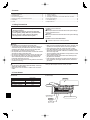
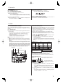
Air-Conditioners
Indoor unit
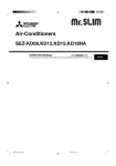
PKA-A·KA
PKA-A·KAL
English
OPERATION MANUAL
FOR USER
For safe and correct use, please read this operation manual thoroughly before operating the air-conditioner unit.
POUR L’UTILISATEUR
English
Contents
1.
2.
3.
4.
5.
6.
Safety Precautions ................................................................2
Parts Names..........................................................................2
Screen Configuration.............................................................5
Setting the Day of the Week and Time ..................................5
Operation...............................................................................5
Timer .....................................................................................7
7. Other Functions ...................................................................10
8. Function Selection ...............................................................11
9. Emergency Operation for Wireless Remote-controller ........15
10.Care and Cleaning ..............................................................15
11. Troubleshooting ...................................................................16
12.Specifications ......................................................................17
1. Safety Precautions
Before installing the unit, make sure you read all the
“Safety Precautions”.
The “Safety Precautions” provide very important
points regarding safety. Make sure you follow them.
Please report to or take consent by the supply
authority before connection to the system.
Symbols used in the text
Warning:
Describes precautions that should be observed to prevent danger
of injury or death to the user.
Caution:
Describes precautions that should be observed to prevent damage
to the unit.
Symbols used in the illustrations
: Indicates a part which must be grounded.
Warning:
• For appliances not accessible to the general public.
• The unit must not be installed by the user. Ask the dealer or an
authorized company to install the unit. If the unit is installed
improperly, water leakage, electric shock or fire may result.
• Do not stand on, or place any items on the unit.
• Do not splash water over the unit and do not touch the unit with
wet hands. An electric shock may result.
• Do not spray combustible gas close to the unit. Fire may result.
• Do not place a gas heater or any other open-flame appliance
where it will be exposed to the air discharged from the unit.
Incomplete combustion may result.
• Do not remove the front panel or the fan guard from the outdoor
unit when it is running.
Caution:
• Do not use any sharp object to push the buttons, as this may
damage the remote controller.
• Never block or cover the indoor or outdoor unit’s air inlets or
outlets.
• When you notice exceptionally abnormal noise or vibration, stop
operation, turn off the power switch, and contact your dealer.
• Never insert fingers, sticks etc. into the air inlets or outlets.
• If you detect odd smells, stop using the unit, turn off the power
switch and consult your dealer. Otherwise, a breakdown, electric
shock or fire may result.
• This air conditioner is NOT intended for use by children or infirm
persons without supervision.
• Young children must be supervised to ensure that they do not
play with the air conditioner.
• If the refrigeration gas blows out or leaks, stop the operation of
the air conditioner, thoroughly ventilate the room, and contact
your dealer.
Disposing of the unit
When you need to dispose of the unit, consult your dealer.
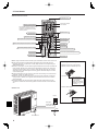
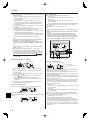
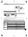
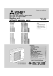
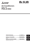
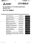
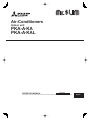
2. Parts Names
Indoor Unit
Fan speed
Vane
Louver
Filter
Filter cleaning indication
PKA-A·KA(L)
PKA-A·KA(L)
3 speeds (with auto)
Auto with swing
Manual
Normal
100 hr
Front grille
Filter
Air inlet
Air outlet
Emergency operation switch
Louver
Vane
2
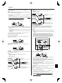
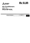
2. Parts Names
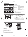
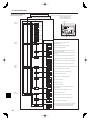
Wired Remote-Controller
“Sensor” indicator
Display Section
For purposes of this explanation,
all parts of the display are shown
as lit. During actual operation,
only the relevant items will be
displayed.
Identifies the current operation
Displayed when the remote controller
sensor is used.
Day-of-Week
Shows the current day of the week.
Time/Timer Display
“Locking function” indicator
Shows the current time, unless the simple or Auto Off
timer is set.
If the simple or Auto Off timer is set, shows the time
remaining.
Indicates that remote controller
buttons have been locked.
“Clean the filter” indicator
Shows the operation mode, etc.
* Multi language display is
supported.
Comes on when it is time to clean
the filter.
TIME SUN MON TUE WED THU FRI SAT
TIMER
Hr
ON
AFTER
FUNCTION
FILTER
°F°C
°F°C
“Centrally Controlled” indicator
Indicates that operation of the
remote controller has been
prohibited by a master controller.
“Timer is Off” indicator
Indicates that the timer is off.
Shows the target temperature.
The indicator comes on if the
corresponding timer is set.
WEEKLY
SIMPLE
AUTO OFF
ONLY1Hr.
Fan Speed indicator
Shows the selected fan speed.
Airflow up/down direction indicator
Room Temperature display
Ventilation indicator
The indicator
shows the direction
of the outcoming airflow.
Shows the room temperature. The room
temperature display range is 8–39 °C,
46–102 °F.
The display blinks if the temperature is
less than 8 °C, 46 °F or 39 °C, 102 °F or
more.
Appears when the unit is running in
Ventilation mode.
“One Hour Only” indicator
Temperature Setting
Timer indicators
AFTER OFF
ERROR CODE
Displayed if the airflow is set to Low
and downward during COOL or DRY
operation mode. (Operation varies
according to model.)
The indicator goes off after one hour
when the airflow up/down direction
also changes.
Louver display
Indicates the action of the swing louver.
Does not appear if the louver is stationary.
(Power On indicator)
Indicates that the power is on.
Operation Section
ON/OFF button
Temperature set buttons
Down
Fan Speed button
Up
Timer Menu button
(Timer monitor/Timer set button)
Filter
button
(<Enter> button)
Operation mode button
(Back button)
TEMP.
ON/OFF
Set Time buttons
Check button
(Clear button)
Back
Ahead
Test Run button
MENU
BACK
MONITOR/SET
ON/OFF
FILTER
DAY
CHECK TEST
Airflow up/down button
Timer On/Off button
(Set Day button)
PAR-21MAA
CLOCK
OPERATION
CLEAR
Louver button
(
Operation button)
To preceding
operation number.
Opening the
door.
Ventilation button
(
Operation button)
Built-in temperature sensor
To next operation
number.
Note:
“PLEASE WAIT” message
This message is displayed for approximately 3 minutes when power is supplied to the indoor unit or when the unit is recovering from a power failure.
“NOT AVAILABLE” message
This message is displayed if a button is pressed to operate a function that the indoor unit does not have.
If a single remote controller is used to simultaneously operate multiple indoor units that are different models, this message will not be displayed if
any of the indoor units is equipped with the function.
3
2. Parts Names
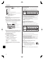
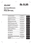
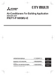
Wireless Remote-Controller
Transmission area
Transmission indicator
Remote controller display
Timer indicator
* For explanation purposes, all of the items
that appear in the display are shown.
* All items are displayed when the Reset
button is pressed.
Operation areas
ON/OFF button
Temperature set buttons
Fan Speed button (Changes fan speed)
Timer Off button
Timer On button
Airflow button (Changes airflow up/down direction)
Hour button
Minute button
Mode button (Changes operation mode)
Set Time button (Sets the time)
Check button
Louver button (Changes left/right direction)
Test Run button
Reset button
When using the wireless remote controller, point it towards the receiver on the indoor unit.
If the remote controller is operated within approximately two minutes after power is
supplied to the indoor unit, the indoor unit may beep twice as the unit is performing the
initial automatic check.
The indoor unit beeps to confirm that the signal transmitted from the remote controller has
been received. Signals can be received up to approximately 7 meters, 275 19/32 inch in
a direct line from the indoor unit in an area 45° to the left and right of the unit. However,
illumination such as fluorescent lights and strong light can affect the ability of the indoor
unit to receive signals.
If the operation lamp near the receiver on the indoor unit is flashing, the unit needs to be
inspected. Consult your dealer for service.
Handle the remote controller carefully! Do not drop the remote controller or subject it to
strong shocks. In addition, do not get the remote controller wet or leave it in a location
with high humidity.
To avoid misplacing the remote controller, install the holder included with the remote
controller on a wall and be sure to always place the remote controller in the holder after
use.
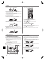
Battery installation/replacement
1. Remove the top cover, insert two AAA
batteries, and then install the top cover.
1
2
Top cover
3
Two AAA batteries
Insert the negative
(–) end of each
battery first. Install the
batteries in the correct
directions (+, –)!
2. Press the Reset button.
Outdoor unit
Power
Press the Reset button
with an object that has
a narrow end.
Ref. Pipes
Indoor-Outdoor
Connection wire
Earth
Service Panel
4
3. Screen Configuration
Function Selection of remote controller
<Screen Types>
For details on setting the language for the remote controller display, refer
to section 8. Function Selection.
The initial language setting is English.
Function Selection of remote controller:
Set the functions and ranges available to the
remote controller (timer functions, operating
restrictions, etc.)
Set Day/Time:
Set the current day of the week or time.
Standard Control Screens:
View and set the air conditioning system’s
operating status
Timer Monitor:
View the currently set timer (weekly timer,
simple timer, or Auto Off timer)
Timer Setup:
Set the operation of any of the timers (weekly
timer, simple timer, or Auto Off timer).
Set Day/Time
TIME SUN
A
D
C
Standard Control Screens
°F
°F
OFF
ON
B
C
Timer Monitor
Timer Setup
SUN MON TUE WED THU FRI SAT
MON
TIMER
OFF
B
°F
WEEKLY
WEEKLY
<How to change the screen>
A : Hold down both the Mode button and the Timer On/Off button for 2
seconds.
B : Press the Timer Menu button.
C : Press the Operation mode (Back) button.
D : Press either of the Set Time buttons ( or ).
4. Setting the Day of the Week and Time
3
1
Day of the Week
& Time display
2
TIME SUN
TIME SUN
Day of the Week Setting
4
Time Setting
°F
°F
TEMP.
2
MENU
BACK
MONITOR/SET
PAR-21MAA
9
ON/OFF
ON/OFF
4
FILTER
DAY
CHECK TEST
OPERATION
CLOCK
CLEAR
a
Note:
The day and time will not appear if clock use has been disabled at Function
Selection of remote controller.
1. Press the
or
Set Time button a to show display 2.
2. Press the Timer On/Off (Set Day) button 9 to set the day.
* Each press advances the day shown at 3 :
Sun → Mon → ... → Fri → Sat.
3. Press the appropriate Set Time button a as necessary to set the
time.
* As you hold the button down, the time (at 4) will increment first in
minute intervals, then in ten-minute intervals, and then in one-hour
intervals.
4. After making the appropriate settings at Steps 2 and 3, press the Filter
button 4 to lock in the values.
5. Operation
6
4
5
8
7
1
2
3
3
2
°F
°F
TEMP.
MENU
BACK
MONITOR/SET
PAR-21MAA
ON/OFF
ON/OFF
FILTER
DAY
CLOCK
2
5
6
3
7
CHECK TEST
OPERATION
7 8
1
5
CLEAR
1
3
6
5.1. Turning ON/OFF
<To Start Operation>
Press the ON/OFF button 1.
• The ON lamp 1 and the display area come on.
5
2
6
7
<To Stop Operation>
Press the ON/OFF button 1 again.
• The ON lamp 1 and the display area go dark.
Note:
Even if you press the ON/OFF button immediately after shutting down
the operation is progress, the air conditioner will not start for about three
minutes. This is to prevent the internal components from being damaged.
5
5. Operation
5.2. Operation mode select
Press the operation mode (
operation mode 2.
5.4. Fan speed setting
) button 2 and select the
Cool mode
Dry mode
Fan mode
FAN SPEED
Heat mode <Only heat pump type>
Automatic (cool/heat) operation mode <Only heat pump type>
Ventillation mode
Only indicated on the following condition
Wired remote controller used
LOSSNAY connected
Automatic operation
According to a set temperature, cooling operation starts if the room
temperature is too hot and heating operation starts if the room
temperature is too cold.
During automatic operation, if the room temperature changes and
remains 2 °C or more above the set temperature for 15 minutes, the
air conditioner switches to cool mode. In the same way, if the room
temperature remains 2 °C or more below the set temperature for 15
minutes, the air conditioner switches to heat mode.
Cool mode
Press the Fan Speed button 5 as many times as necessary while the
system is running.
• Each press changes the force. The currently selected speed is
shown at 5.
• The change sequence, and the available settings, are as follows.
15 minutes (switches
from heating to cooling)
Set temperature +2°C, +4°F
Set temperature
Set temperature -2°C, -4°F
15 minutes (switches
from cooling to heating )
Because the room temperature is automatically adjusted in order to
maintain a fixed effective temperature, cooling operation is performed
a few degrees warmer and heating operation is performed a few
degrees cooler than the set room temperature once the temperature is
reached (automatic energy-saving operation).
5.3. Temperature setting
To decrease the room temperature:
Press
button 3 to set the desired temperature.
The selected temperature is displayed 3.
To increase the room temperature:
button 3 to set the desired temperature.
Press
The selected temperature is displayed 3.
• Available temperature ranges are as follows:
Cooling/Drying:
19 - 30 °C, 66 °F - 86 °F
Heating:
17 - 28 °C, 63 °F - 82 °F
Automatic:
19 - 28 °C, 66 °F - 82 °F
• The display flashes either 8 °C - 39 °C, 46 °F - 102 °F to inform
you if the room temperature is lower or higher than the displayed
temperature.
3-speed
+
Auto
Display
Speed 1
Speed 2
Speed 3
Auto
Note:
The number of available fan speeds depends on the type of unit
connected. Note also that some units do not provide an “Auto” setting.
In the following cases, the actual fan speed generated by the unit will differ
from the speed shown the remote controller display.
1. While the display is showing “STAND BY” or “DEFROST”.
2. When the temperature of the heat exchanger is low in the heat mode.
(e.g. immediately after heat operation starts)
3. In HEAT mode, when room temperature is higher than the temperature
setting.
4. When the unit is in DRY mode.
5.5. Airflow up/down direction setting
<To change the airflow up/down direction>
With the unit running, press the Airflow up/down button 6 as
necessary.
• Each press changes the direction. The current direction is shown at
6.
• The change sequence, and the available settings, are as follows.
Airflow
Wireless
remotecontroller
Wired
remotecontroller
Swing
Swing
1
Auto
2
1
2
3
3
4
4
5
* Note that during swing operation, the directional indication on the
screen does not change in sync with the directional vanes on the
unit.
* Some models do not support directional settings.
Note:
Available directions depend on the type of unit connected. Note also that
some units do not provide an “Auto” setting.
In the following cases, the actual air direction will differ from the direction
indicated on the remote controller display.
1. While the display is showing “STAND BY” or “DEFROST”.
2. Immediately after starting heater mode (while the system is waiting for
the operation mode change to take effect).
3. In heat mode, when room temperature is higher than the temperature
setting.
<[Manual] To Change the Airflow’s Left/Right Direction>
* The louver button 7 cannot be used.
Model PKA-A·KA(L)
• Stop the unit operation, hold the lever of the louver
airflow vanes, and adjust to the desired direction.
* Do not set to the inside direction when the unit is in
the cooling or drying mode because there is a risk
of condensation and water dripping.
Caution:
To prevent falls, maintain a stable footing when operating the unit.
6
5. Operation
5.6. Ventillation
To change the ventilator force:
Press the Ventilation button 8 as necessary.
• Each press toggles the setting, as shown below.
For LOSSNAY combination
5.6.1. For Wired Remote-controller
To run the ventilator together with the indoor unit:
Press the ON/OFF button 1.
• The Vent indication appears on the screen (at 8). The ventilator
will now automatically operate whenever the indoor unit is running.
To run the ventilator independently:
Press the Mode button 2 until
will cause the ventilator to start.
Low
High
5.6.2. For Wireless Remote-controller
appears on the display. This
The ventillator will automatically operate when the indoor unit turns on.
No indication on the wireless remote controller.
6. Timer
6.1. For Wired Remote-controller
You can use Function Selection of remote controller to select which of
three types of timer to use: 1 Weekly timer, 2 Simple timer, or 3 Auto
Off timer.
6.1.1. Weekly Timer
The weekly timer can be used to set up to eight operations for each
day of the week.
• Each operation may consist of any of the following: ON/OFF time
together with a temperature setting, or ON/OFF time only, or
temperature setting only.
• When the current time reaches a time set at this timer, the air
conditioner carries out the action set by the timer.
Time setting resolution for this timer is 1 minute.
Note:
*1. Weekly Timer/Simple Timer/Auto Off Timer cannot be used at the same
time.
*2. The weekly timer will not operate when any of the following conditions is
in effect.
The timer feature is off; the system is in an malfunction state; a test run
is in progress; the remote controller is undergoing self-check or remote
controller check; the user is in the process of setting a function; the user
is in the process of setting the timer; the user is in the process of setting
the current day of the week or time; the system is under central control.
(Specifically, the system will not carry out operations (unit on, unit off, or
temperature setting) that are prohibited during these conditions.)
Sunday
Monday
...
Saturday
• 8:30
No. 1
• ON
• 73 °F
No. 2
• 10:00
• 10:00
• 10:00
• 10:00
• OFF
• OFF
• OFF
• OFF
No. 8
3 Day Setting
SUN
ON
1
°F
WEEKLY
TEMP.
MENU
PAR-21MAA
Op No.
...
Operation No.
4
2
BACK
<How to Set the Weekly Timer>
1. Be sure that you are at a standard control screen, and that the weekly
timer indicator 1 is shown in the display.
2. Press the Timer Menu button b, so that the “Set Up” appears on the
screen (at 2). (Note that each press of the button toggles the display
between “Set Up” and “Monitor”.)
3. Press the Timer On/Off (Set Day) button 9 to set the day. Each
press advances the display at 3 to the next setting, in the following
sequence: “Sun Mon Tues Wed Thurs Fri Sat” → “Sun” → ... → “Fri”
→ “Sat” → “Sun Mon Tues Wed Thurs Fri Sat”...
4. Press the
or
operation button (7 or 8) as necessary to select
the appropriate operation number (1 to 8) 4.
* Your inputs at Steps 3 and 4 will select one of the cells from the
matrix illustrated below.
(The remote-controller display at left shows how the display would
appear when setting Operation 1 for Sunday to the values indicated
below.)
Setup Matrix
MONITOR/SET
ON/OFF
ON/OFF
FILTER
DAY
CHECK TEST
OPERATION
CLOCK
CLEAR
3
1
b
4
0
<Operation 1 settings for Sunday>
<Operation 2 settings for every day>
Start the air conditioner at 8:30, with
the temperature set to 73 °F.
Turn off the air conditioner at 10:00.
Note:
By setting the day to “Sun Mon Tues Wed Thurs Fri Sat”, you can set the
same operation to be carried out at the same time every day.
(Example: Operation 2 above, which is the same for all days of the week.)
<Setting the Weekly Timer>
Shows the time
setting
5
6
Shows the selected operation (ON or OFF)
* Does not appear if operation is not set.
SUN
ON
°F
WEEKLY
2
a
9
78
7
Shows the temperature setting
* Does not appear if temperature is
not set.
5. Press the appropriate Set Time button a as necessary to set the
desired time (at 5).
* As you hold the button down, the time first increments in minute
intervals, then in ten-minute intervals, and then in one-hour
intervals.
6. Press the ON/OFF button 1 to select the desired operation (ON or
OFF), at 6.
* Each press changes the next setting, in the following sequence:
No display (no setting) → “ON” → “OFF”
7
6. Timer
7. Press the appropriate Temperature set button 3 to set the desired
temperature (at 7).
* Each press changes the setting, in the following sequence: No
display (no setting) ⇔ 75 ⇔ 77 ⇔ ... ⇔ 84 ⇔ 86 ⇔ 54 ⇔ ... ⇔
73 ⇔ No display.
(Available range: The range for the setting is 12 °C, 54 °F to
30 °C, 86 °F. The actual range over which the temperature can
be controlled, however, will vary according to the type of the
connected unit.)
8. After making the appropriate settings at Steps 5, 6 and 7, press the
button 4 to lock in the values.
Filter
To clear the currently set values for the selected operation, press
and quickly release the Check (Clear) button 0 once.
* The displayed time setting will change to “—:—”, and the On/Off
and temperature settings will all disappear.
(To clear all weekly timer settings at once, hold down the Check
(Clear) button 0 for two seconds or more. The display will begin
flashing, indicating that all settings have been cleared.)
Note:
Your new entries will be cancelled if you press the Operation mode
button 4.
(Back) button 2 before pressing the Filter
If you have set two or more different operations for exactly the same
time, only the operation with the highest Operation No. will be carried
out.
6.1.2. Simple Timer
You can set the simple timer in any of three ways.
• Start time only:
The air conditioner starts when the set time has elapsed.
• Stop time only:
The air conditioner stops when the set time has elapsed.
• Start & stop times:
The air conditioner starts and stops at the respective elapsed times.
The simple timer (start and stop) can be set only once within a 72hour period.
The time setting is made in hour increments.
Note:
*1. Weekly Timer/Simple Timer/Auto Off Timer cannot be used at the same
time.
*2. The simple timer will not operate when any of the following conditions is
in effect.
The timer is off; the system is in malfunction state; a test run is in
progress; the remote controller is undergoing self-check or remote
controller check; the user is in the process of selecting a function; the
user is in the process of setting the timer; the system is under central
control. (Under these conditions, On/Off operation is prohibited.)
Hr
ON
AFTER
9. Repeat Steps 3 to 8 as necessary to fill as many of the available
cells as you wish.
10.Press the Operation mode (Back) button 2 to return to the
standard control screen and complete the setting procedure.
11. To activate the timer, press the Timer On/Off button 9, so that the
“Timer Off” indication disappears from the screen. Be sure that
the “Timer Off” indication is no longer displayed.
* If there are no timer settings, the “Timer Off” indication will flash
on the screen.
SIMPLE
TEMP.
MENU
BACK
PAR-21MAA
2
<How to View the Weekly Timer Settings>
8
9
ON/OFF
MONITOR/SET
FILTER
DAY
a
CHECK TEST
OPERATION
CLOCK
2
SUN
4
Hr
WEEKLY
Timer Setting
1
3
ON
AFTER
SIMPLE
1. Be sure that the weekly timer indicator is visible on the screen (at
1).
2. Press the Timer Menu button b so that “Monitor” is indicated on
the screen (at 8).
3. Press the Timer On/Off (Set Day) button 9 as necessary to select
the day you wish to view.
or
operation button (7 or 8) as necessary to
4. Press the
change the timer operation shown on the display (at 9).
* Each press will advance to the next timer operation, in order of
time setting.
5. To close the monitor and return to the standard control screen,
press the Operation mode (Back) button 2.
<To Turn Off the Weekly Timer>
Press the Timer On/Off button 9 so that “Timer Off” appears at 0.
TIME SUN
°F
°F
WEEKLY
<To Turn On the Weekly Timer>
Press the Timer On/Off button 9 so that the “Timer Off” indication (at 0)
goes dark.
TIME SUN
°F
8
0
ON
°F
0
b
4
9
OFF
0
CLEAR
1
<How to Set the Simple Timer>
Timer Settings
TIMER
ON/OFF
°F
WEEKLY
1
Action (On or Off)
* “— —” is displayed if there is no
setting.
1. Be sure that you are at a standard control screen, and that the simple
timer indicator is visible in the display (at 1).
When something other than the Simple Timer is displayed, set it to
SIMPLE TIMER using the function selection of remote controller (see
8.[4]–3 (3)) timer function setting.
2. Press the Timer Menu button b, so that the “Set Up” appears on the
screen (at 2). (Note that each press of the button toggles the display
between “Set Up” and “Monitor”.)
3. Press the ON/OFF button 1 to display the current ON or OFF simple
timer setting. Press the button once to display the time remaining to
ON, and then again to display the time remaining to OFF. (The ON/
OFF indication appears at 3).
• “ON” timer:
The air conditioner will start operation when the specified number of
hours has elapsed.
• “OFF” timer:
The air conditioner will stop operation when the specified number of
hours has elapsed.
4. With “ON” or “OFF” showing at 3: Press the appropriate Set Time
button a as necessary to set the hours to ON (if “ON” is displayed) or
the hours to OFF (if “OFF” is displayed) at 4.
• Available Range: 1 to 72 hours
5. To set both the ON and OFF times, repeat Steps 3 and 4.
* Note that ON and OFF times cannot be set to the same value.
6. To clear the current ON or OFF setting: Display the ON or OFF setting
(see step 3) and then press the Check (Clear) button 0 so that the
time setting clears to “—” at 4. (If you want to use only an ON setting
or only an OFF setting, be sure that the setting you do not wish to use
is shown as “—”.)
6. Timer
7. After completing steps 3 to 6 above, press the Filter
lock in the value.
button 4 to
Note:
Your new settings will be cancelled if you press the Operation mode (Back)
button 4.
button 2 before pressing the Filter
Example 2:
Start the timer, with OFF time is sooner than ON time
ON Setting: 5 hours
OFF Setting: 2 hours
Hr
AFTER OFF
8. Press the Operation mode (Back) button 2 to return to the standard
control screen.
9. Press the Timer On/Off button 9 to start the timer countdown. When
the timer is running, the timer value is visible on the display. Be sure
that the timer value is visible and appropriate.
At Timer Start
°F
°F
SIMPLE
Hr
At 2 hours after timer start
ON
AFTER
SIMPLE
<Viewing the Current Simple Timer Settings>
Timer Setting
6
5
Hr
°F
ON
SIMPLE
AFTER OFF
SIMPLE
1
1. Be sure that the simple timer indicator is visible on the screen (at 1).
2. Press the Timer Menu button b, so that the “Monitor” appears on the
screen (at 5).
• If the ON or OFF simple timer is running, the current timer value will
appear at 6.
• If ON and OFF values have both been set, the two values appear
alternately.
3. Press the Operation mode (Back) button 2 to close the monitor
display and return to the standard control screen.
<To Turn Off the Simple Timer...>
Press the Timer On/Off button 9 so that the timer setting no longer
appears on the screen (at 7).
Display changes to show the timer’s ON
setting (hours remaining to ON).
The time displayed is ON setting (5 hours)
– OFF setting (2 hours) = 3 hours.
At 5 hours after timer start
°F
TIMER
Display shows the timer’s OFF setting (hours
remaining to OFF).
The air conditioner comes on, and will
continue to run until someone turns it off.
6.1.3. Auto Off Timer
This timer begins countdown when the air conditioner starts, and
shuts the air conditioner off when the set time has elapsed.
Available settings run from 30 minutes to 4 hours, in 30-minute
intervals.
Note:
*1. Weekly Timer/Simple Timer/Auto Off Timer cannot be used at the same
time.
*2. The Auto Off timer will not operate when any of the following conditions
is in effect.
The timer is off; the system is in malfunction state; a test run is in
progress; the remote controller is undergoing self-check or remote
controller check; the user is in the process of selecting a function; the
user is in the process of setting the timer; the system is under central
control. (Under these conditions, On/Off operation is prohibited.)
7
°F
AFTER
°F
OFF
SIMPLE
AUTO OFF
<To Turn On the Simple Timer...>
Press the Timer On/Off button 9 so that the timer setting becomes
visible at 7.
7
TEMP.
MENU
BACK
PAR-21MAA
Hr
MONITOR/SET
ON/OFF
ON/OFF
b
4
FILTER
DAY
CHECK TEST
OPERATION
CLOCK
CLEAR
ON
AFTER
°F
°F
SIMPLE
Examples
If ON and OFF times have both been set at the simple timer, operation
and display are as indicated below.
Example 1:
Start the timer, with ON time set sooner than OFF time
ON Setting: 3 hours
OFF Setting: 7 hours
Hr
ON
AFTER
At Timer Start
SIMPLE
Display shows the timer’s ON setting (hours
remaining to ON).
At 3 hours after timer start
Hr
AFTER OFF
°F
°F
SIMPLE
Display changes to show the timer’s OFF
setting (hours remaining to OFF).
The time displayed is OFF setting (7 hours)
– ON setting (3 hours) = 4 hours.
At 7 hours after timer start
SIMPLE
The air conditioner goes off, and will remain
off until someone restarts it.
2
a
9
<How to Set the Auto Off Timer>
2
3
AFTER
Timer Setting
OFF
AUTO OFF
1
1. Be sure that you are at a standard control screen, and that the Auto
Off timer indicator is visible in the display (at 1).
When something other than the Auto Off Timer is displayed, set it to
AUTO OFF TIMER using the function selection of remote controller
(see 8.[4]–3 (3)) timer function setting.
2. Hold down the Timer Menu button b for 3 seconds, so that the “Set
Up” appears on the screen (at 2).
(Note that each press of the button toggles the display between “Set
Up” and “Monitor”.)
3. Press the appropriate Set Time button a as necessary to set the OFF
time (at 3).
button 4 to lock in the setting.
4. Press the Filter
Note:
Your entry will be cancelled if you press the Operation mode (Back) button 2
button 4.
before pressing the Filter
5. Press the Operation mode (Back) button 2 to complete the setting
procedure and return to the standard control screen.
6. If the air conditioner is already running, the timer starts countdown
immediately. Be sure to check that the timer setting appears
correctly on the display.
9
6. Timer
6.2. For wireless remote controller
<Checking the Current Auto Off Timer Setting>
4
5
Timer Setting
TIMER
AFTER
OFF
A
1
AUTO OFF
1. Be sure that the “Auto Off” is visible on the screen (at 1).
2. Hold down the Timer Menu button b for 3 seconds, so that “Monitor”
is indicated on the screen (at 4).
• The timer remaining to shutdown appears at 5.
3. To close the monitor and return to the standard control screen, press
the Operation mode (Back) button 2.
13
<To Turn Off the Auto Off Timer...>
Hold down the Timer On/Off button 9 for 3 seconds, so that “Timer
Off” appears (at 6) and the timer value (at 7) disappears.
2
7
AUTO START
AUTO STOP
°F
°F
6
AUTO OFF
Alternatively, turn off the air conditioner itself. The timer value (at 7)
will disappear from the screen.
7
AUTO OFF
<To Turn On the Auto Off Timer...>
Hold down the Timer On/Off button 9 for 3 seconds. The “Timer
Off” indication disappears (at 6), and the timer setting comes on the
display (at 7).
Alternatively, turn on the air conditioner. The timer value will appear at
7.
1 Press the
or
button (TIMER SET).
• Time can be set while the following symbol is blinking.
OFF timer : A
is blinking.
ON timer : A
is blinking.
h
min
2 Use the
and
buttons to set the desired time.
3 Canceling the timer.
AUTO STOP
To cancel the OFF timer, press the
button.
AUTO START
To cancel the ON timer, press the
button.
• It is possible to combine both OFF and ON timers.
• Pressing the
ON/OFF button of the remote controller during timer
mode to stop the unit will cancel the timers.
• If the current time has not been set, the timer operation cannot be
used.
7
AFTER
OFF
°F
°F
6
AUTO OFF
7. Other Functions
7.1. Locking the Remote Controller Buttons
(Operation function limit controller)
If you wish, you can lock the remote controller buttons. You can use
the Function Selection of remote controller to select which type of
locking function to use. (For information about selecting the lock type,
see section 8, item [4]–2 (1)).
Specifically, you can use either of the following two locking functions.
1 Lock All Buttons:
Locks all of the buttons on the remote controller.
2 Lock All Except ON/OFF:
Locks all buttons other than the ON/OFF button.
°F
1
Locking function
indicator
FUNCTION
°F
• If you press a locked button, the “Locking function” indicator (at 1)
will blink on the display.
°F
ON/OFF
BACK
PAR-21MAA
10
MONITOR/SET
ON/OFF
FILTER
DAY
CLOCK
CHECK TEST
OPERATION
CLEAR
FUNCTION
1
°F
1
1
MENU
1
<How to Unlock the Buttons>
1. While holding down the Filter button 4, press and hold down the ON/
OFF button 1 for 2 seconds—so that the “Locking function” indicator
disappears from the screen (at 1).
TIME SUN
TEMP.
FUNCTION
°F
Note:
The “Locking function” indicator appears on the screen to indicate that
buttons are currently locked.
°F
<How to Lock the Buttons>
1. While holding down the Filter button 4, press and hold down the
ON/OFF button 1 for 2 seconds. The “Locking function” indicator
appears on the screen (at 1), indicating that the locking function is
now engaged.
* If locking has been disabled in Function Selection of remote
controller, the screen will display the “Not Available” message when
you press the buttons as described above.
4
°F
°F
7. Other Functions
7.2. Error Codes indication
ERROR CODE
ON/OFF
Indoor Unit’s
Refrigerant Address
Error Code
ON lamp
(Flashing)
Indoor Unit No.
Alternating Display
If you have entered contact number to be called in the event of a problem, the screen displays this number.
(You can set this up under Function Selection of remote controller. For information, refer to section 8.)
If the ON lamp and error code are both flashing: This means that the air conditioner is out of order and operation has been stopped (and cannot
resume). Take note of the indicated unit number and error code, then switch off the power to the air conditioner and call your dealer or servicer.
When the Check button is pressed:
CALL:XXXX
XXX:XXX
ERROR CODE
°F
°F
ON/OFF
ON/OFF
Error Code
If only the error code is flashing (while the ON lamp remains lit): Operation is continuing, but there may be a problem with the system. In this case,
you should note down the error code and then call your dealer or servicer for advice.
* If you have entered contact number to be called in the event of a problem, push the Check button to display it on the screen. (You can set this up
under Function Selection of remote controller. For information, refer to section 8.)
8. Function Selection
Function selection of remote controller
The setting of the following remote controller functions can be changed using the remote controller function selection mode. Change the setting when
needed.
Item 1
1. Change Language
(“CHANGE
LANGUAGE”)
2. Function limit
(“FUNCTION
SELECTION”)
3. Operation mode
selection
(“MODE SELECTION”)
Item 2
Language setting to display
(1) Operation function limit setting (operation lock) (“LOCKING
FUNCTION”)
(2) Use of automatic mode setting (“SELECT AUTO MODE”)
(3) Temperature range limit setting (“LIMIT TEMP FUNCTION”)
(1) Remote controller main/sub setting (“CONTROLLER MAIN/
SUB”)
(2) Use of clock setting (“CLOCK”)
(3) Timer function setting (“WEEKLY TIMER”)
(4) Contact number setting for error situation (“CALL.”)
4. Display change
(“DISP MODE
SETTING”)
(1) Temperature display °C/°F setting (“TEMP MODE °C/°F”)
(2) Suction air temperature display setting (“ROOM TEMP DISP
SELECT”).
(3) Automatic cooling/heating display setting (“AUTO MODE DISP
C/H”)
Item 3 (Setting content)
• Display in multiple languages is possible
• Setting the range of operation limit (operation locking function)
• Setting the use or non-use of “automatic” operation mode
• Setting the temperature adjustable range (maximum, minimum)
• Selecting main or sub remote controller
* When two remote controllers are connected to one group, one
controller must be set to sub.
• Setting the use or non-use of clock function
• Setting the timer type
• Contact number display in case of error
• Setting the telephone number
• Setting the temperature unit (°C or °F) to display
• Setting the use or non-use of the display of indoor (suction) air
temperature
• Setting the use or non-use of the display of “Cooling” or “Heating”
display during operation with automatic mode
11
8. Function Selection
Normal display
(Display when the air condition is not running)
[Function selection flowchart]
Setting language (English)
Hold down the E button and press the D button for 2 seconds.
E Press the operation mode button.
G Press the TIMER MENU button.
D Press the TIMER ON/OFF button.
Hold down the E button and press the D button for 2 seconds.
Remote controller function selection mode
Item1
G
Change
Language
Item2
Dot display
English
G
Germany
E
F
Spanish
TEMP.
ON/OFF
Russian
E
G
Italy
G
MENU
BACK
MONITOR/SET
PAR-21MAA
ON/OFF
FILTER
DAY
CLOCK
CHECK TEST
OPERATION
CLEAR
Chinese
Japanese
OFF
D
G
E
D
D
G
G
D
Operation locking function setting is not used.
(Initial setting value)
on1
Operation lock setting is except On/Off button.
on2
Operation lock setting is All buttons.
ON
The automatic mode is displayed when the operation mode is
selected. (Initial setting value)
D
OFF
D
E
D
Item3
D
G
B
H
C
French
Function
selection
I
A
The automatic mode is not displayed when the operation mode
is selected.
The temperature range limit is not active. (Initial setting value)
OFF
D
D
The temperature range can be changed on cool/dry operation
mode.
The temperature range can be changed on heat operation mode.
The temperature range can be changed on automatic mode.
G
Operation
mode
selection
D
G
D
D
E
G
The remote controller will be the main controller. (Initial setting value)
D
D
The clock function can be used. (Initial setting value)
ON
D
OFF
D
The clock function can not be used.
Weekly timer can be used. (Initial setting value)
G
D
G
The remote controller will be the sub controller.
D
Auto off timer can be used.
Simple timer can be used.
Timer mode can not be used.
D
D
Display
mode setting
D
G
G
D
D
G
G
D
D
D
12
OFF
D
The set contact numbers are not displayed in case of error.
(Initial setting value)
CALL-
The set contact numbers are displayed in case of error.
C
The temperature unit °C is used.
D
F
Room air temperature is displayed. (Initial setting value)
ON
D
OFF
ON
D
OFF
The temperature unit °F is used. (Initial setting value)
Room air temperature is not displayed.
One of “Automatic cooling” and “Automatic heating” is displayed
under the automatic mode is running. (Initial setting value)
Only “Automatic” is displayed under the automatic mode.
8. Function Selection
[Detailed setting]
[4]–1. CHANGE LANGUAGE setting
The language that appears on the dot display can be selected.
• Press the [ MENU] button G to change the language.
1 English (GB), 2 German (D), 3 Spanish (E), 4 Russian (RU),
5 Italian (I), 6 Chinese (CH), 7 French (F), 8 Japanese (JP)
Refer to the dot display table.
[4]–2. Function limit
(1) Operation function limit setting (operation locking function)
• To switch the setting, press the [ ON/OFF] button D.
1 no1 : Operation lock setting is made on all buttons other than
the [ ON/OFF] button.
2 no2 : Operation lock setting is made on all buttons.
3 OFF (Initial setting value): Operation lock setting is not made.
* To make the operation lock setting valid on the normal screen,
it is necessary to press buttons (Press and hold down the
[FILTER] and [ ON/OFF] buttons at the same time for two
seconds.) on the normal screen after the above setting is made.
(2) Use of automatic mode setting
When the remote controller is connected to the unit that has
automatic operation mode, the following settings can be made.
• To switch the setting, press the [ ON/OFF] button D.
1 ON (Initial setting value):
The automatic mode is displayed when the operation mode is
selected.
2 OFF:
The automatic mode is not displayed when the operation
mode is selected.
(3) Temperature range limit setting
After this setting is made, the temperature can be changed within
the set range.
• To switch the setting, press the [ ON/OFF] button D.
1 LIMIT TEMP COOL MODE:
The temperature range can be changed on cool/dry mode.
2 LIMIT TEMP HEAT MODE:
The temperature range can be changed on heat mode.
3 LIMIT TEMP AUTO MODE:
The temperature range can be changed on automatic mode.
4 OFF (initial setting): The temperature range limit is not active.
* When the setting, other than OFF, is made, the temperature
range limit setting on cool, heat and automatic mode is made at
the same time. However, the range cannot be limited when the
set temperature range has not changed.
• To increase or decrease the temperature, press the [ TEMP.
( ) or ( )] button F.
• To switch the upper limit setting and the lower limit setting,
press the [
] button H. The selected setting will flash and the
temperature can be set.
• Settable range
Cool/Dry mode:
Lower limit:19°C ~ 30°C, 67°F ~ 87°F
Upper limit:30°C ~ 19°C, 87°F ~ 67°F
Heat mode:
Lower limit:17°C ~ 28°C, 63°F ~ 83°F
Upper limit:28°C ~ 17°C, 83°F ~ 63°F
Automatic mode:
Lower limit:19°C ~ 28°C, 67°F ~ 83°F
Upper limit:28°C ~ 19°C, 87°F ~ 67°F
[4]–3. Operation mode selection setting
(1) Remote controller main/sub setting
• To switch the setting, press the [ ON/OFF] button D.
1 Main: The controller will be the main controller.
2 Sub:
The controller will be the sub controller.
(2) Use of clock setting
• To switch the setting, press the [ ON/OFF] button D.
1 ON:
The clock function can be used.
2 OFF:
The clock function cannot be used.
(3) Timer function setting
• To switch the setting, press the [ ON/OFF] button D (Choose
one of the followings.).
1 WEEKLY TIMER (initial setting value):
The weekly timer can be used.
2 AUTO OFF TIMER:
The auto off timer can be used.
3 SIMPLE TIMER:
The simple timer can be used.
4 TIMER MODE OFF:
The timer mode cannot be used.
* When the use of clock setting is OFF, the “WEEKLY TIMER”
cannot be used.
(4) Contact number setting for error situation
• To switch the setting, press the [ ON/OFF] button D.
1 CALL OFF:
The set contact numbers are not displayed in case of error.
2 CALL **** *** ****:
The set contact numbers are displayed in case of error.
CALL_:
The contact number can be set when the display is as shown
on the left.
• Setting the contact numbers
To set the contact numbers, follow the following procedures.
Move the flashing cursor to set numbers. Press the [ TEMP.
( ) and ( )] button F to move the cursor to the right (left).
Press the [ CLOCK ( ) and ( )] button C to set the
numbers.
[4]–4. Display change setting
(1) Temperature display °C/°F setting
• To switch the setting, press the [
ON/OFF] button D.
1 °C:
The temperature unit °C is used.
2 °F:
The temperature unit °F is used.
(2) Suction air temperature display setting
• To switch the setting, press the [ ON/OFF] button D.
1 ON:
The suction air temperature is displayed.
2 OFF:
The suction air temperature is not displayed.
(3) Automatic cooling/heating display setting
• To switch the setting, press the [ ON/OFF] button D.
1 ON:
One of “Automatic cooling” and “Automatic heating” is
displayed under the automatic mode is running.
2 OFF:
Only “Automatic” is displayed under the automatic mode.
13
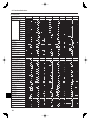
8. Function Selection
[Dot display table]
Selecting language
English
Germany
Spanish
Russian
Italy
Chinese
French
Japanese
English
Germany
Spanish
Russian
Italy
Chinese
French
Japanese
Waiting for start-up
Operation mode
Cool
Dry
Heat
Auto
Auto(Cool)
Auto(Heat)
Fan
Ventilation
Stand by
(Hot adjust)
Defrost
Set temperature
Fan speed
Not use button
Check (Error)
Test run
Self check
Unit function selection
Setting of ventilation
Selecting language
CHANGE LANGUAGE
Function selection
Operation function limit setting
Use of automatic mode setting
Temperature range limit setting
Limit temperature cool/day mode
Limit temperature heat mode
Limit temperature auto mode
Operation mode selection
Remote controller setting MAIN
Remote controller setting SUB
Use of clock setting
Setting the day of the week and
time
Timer set
Timer monitor
Weekly timer
Timer mode off
Auto off timer
Simple timer
Contact number setting of error
situation
Display change
Temperature display °C/°F
setting
Air inlet temperature display
setting
Automatic cool/heat display
setting
14
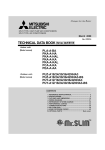
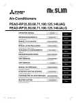
9. Emergency Operation for Wireless Remote-controller
[Combination Cooling and Heating Models]
Cooling
Heating
Stop
PKA-A·KA(L)
C
B
A
D
[Cooling Only Models]
Cooling
Stop
Operation Monitor Display
When the remote controller cannot be used
When the batteries of the remote controller run out or the remote
controller malfunctions, the emergency operation can be done using the
emergency buttons on the grille.
A DEFROST/STAND BY lamp (Orange)
B Operation lamp (Green)
C Emergency operation switch (cooling/heating)
D Receiver
• Each press of the emergency operation switch will toggle the
operation mode.
• Check “COOL/HEAT” with the operation monitor display. (The display
will appear orange for 5 seconds after the switch operation.)
STOP
GREEN
{
COOL
z
HEAT
z
ORANGE
The display will appear orange for 5
{
seconds following the switch operation
{
as indicated at the left, and then it will
z
return to the regular display.
{ Turning off z Lighting
* Operation details at the time of emergency operation are as shown
below.
Note that over the first 30 minutes or so, the temperature adjustment
will not function and the unit will be in continuous operation with the fan
on high.
Operation Mode
Set Temperature
Fan Speed
Airflow Direction Up and Down
COOL
24°C, 75°F
High
Setting 1
HEAT
24°C, 75°F
High
Setting 4 (5)
10. Care and Cleaning
Filter removal
°F
°F
FILTER
Indicates that the filter needs cleaning.
Clean the filter.
When resetting “FILTER” display
When the [FILTER] button is pressed two times successively after
cleaning the filter, the display goes off and is reset.
Note:
When two or more different types of indoor unit are controlled, the
cleaning period differs with the type of filter. When the master unit
cleaning period arrives, “FILTER” is displayed. When the filter display
goes off, the cumulative time is reset.
“FILTER” indicates the cleaning period when the air conditioner was used
under general indoor air conditions by criteria time. Since the degree
of dirtiness depends on the environmental conditions, clean the filter
accordingly.
The filter cleaning period cumulative time differs with the model.
This indication is not available for wireless remote controller.
Cleaning the filters
• Clean the filters using a vacuum cleaner. If you do not have a vacuum
cleaner, tap the filters against a solid object to knock off dirt and dust.
• If the filters are especially dirty, wash them in lukewarm water. Take
care to rinse off any detergent thoroughly and allow the filters to dry
completely before putting them back into the unit.
Caution:
• In removing the filter, precautions must be taken to protect your
eyes from dust. Also, if you have to climb up on a stool to do the
job, be careful not to fall.
• When the filter is removed, do not touch the metallic parts inside
the indoor unit, otherwise injury may result.
PKA-A·KA(L)
A
B
1 Using both hands, pull both the bottom corners of the inlet grille to
open the grille, then lift the filter until it clicks at the stop position.
2 Hold the knobs on the filter and pull the filter up, then pull it out
downward.
(Located in two places, on the left and right.)
A Front grille
B Filter
Caution:
• Do not dry the filters in direct sunlight or by using a heat source,
such as an electric heater: this may warp them.
• Do not wash the filters in hot water (above 50°C), as this may
warp them.
• Make sure that the air filters are always installed. Operating the
unit without air filters can cause malfunction.
Caution:
• Before you start cleaning, stop operation and turn OFF the power
supply.
• Indoor units are equipped with filters to remove the dust of suckedin air. Clean the filters using the methods shown in the following
sketches.
15
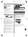
11. Troubleshooting
Having trouble?
Air conditioner does not heat or cool well.
When heating operation starts, warm air does not blow from the indoor
unit soon.
During heat mode, the air conditioner stops before the set room
temperature is reached.
Airflow up/down direction changes during operation or airflow up/down
direction cannot be set.
When the airflow up/down direction is changed, the vanes always move
up and down past the set position before finally stopping at the position.
A flowing water sound or occasional hissing sound is heard.
A cracking or creaking sound is heard.
The room has an unpleasant odor.
A white mist or vapor is emitted from the indoor unit.
Water or vapor is emitted from the outdoor unit.
The operation indicator does not appear in the remote controller display.
“
” appears in the remote controller display.
When restarting the air conditioner soon after stopping it, it does not
operate even though the ON/OFF button is pressed.
Air conditioner operates without the ON/OFF button being pressed.
Air conditioner stops without the ON/OFF button being pressed.
Remote controller timer operation cannot be set.
“PLEASE WAIT” appears in the remote controller display.
An error code appears in the remote controller display.
Draining water or motor rotation sound is heard.
16
Here is the solution. (Unit is operating normally.)
Clean the filter. (Airflow is reduced when the filter is dirty or clogged.)
Check the temperature adjustment and adjust the set temperature.
Make sure that there is plenty of space around the outdoor unit. Is the
indoor unit air inlet or outlet blocked?
Has a door or window been left open?
Warm air does not blow until the indoor unit has sufficiently warmed
up.
When the outdoor temperature is low and the humidity is high,
frost may form on the outdoor unit. If this occurs, the outdoor unit
performs a defrosting operation. Normal operation should begin after
approximately 10 minutes.
During cool mode, the vanes automatically move to the horizontal
(down) position after 1 hour when the down (horizontal) airflow up/
down direction is selected. This is to prevent water from forming and
dripping from the vanes.
During heat mode, the vanes automatically move to the horizontal
airflow up/down direction when the airflow temperature is low or
during defrosting mode.
When the airflow up/down direction is changed, the vanes move to the
set position after detecting the base position.
These sounds can be heard when refrigerant is flowing in the air
conditioner or when the refrigerant flow is changing.
These sounds can be heard when parts rub against each due to
expansion and contraction from temperature changes.
The indoor unit draws in air that contains gases produced from the
walls, carpeting, and furniture as well as odors trapped in clothing,
and then blows this air back into the room.
If the indoor temperature and the humidity are high, this condition may
occur when operation starts.
During defrosting mode, cool airflow may blow down and appear like a
mist.
During cool mode, water may form and drip from the cool pipes and
joints.
During heat mode, water may form and drip from the heat exchanger.
During defrosting mode, water on the heat exchanger evaporates and
water vapor may be emitted.
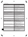
Turn on the power switch. “ ” will appear in the remote controller
display.
During central control, “ ” appears in the remote controller display
and air conditioner operation cannot be started or stopped using the
remote controller.
Wait approximately three minutes.
(Operation has stopped to protect the air conditioner.)
Is the on timer set?
Press the ON/OFF button to stop operation.
Is the air conditioner connected to a central remote controller?
Consult the concerned people who control the air conditioner.
Does “ ” appear in the remote controller display?
Consult the concerned people who control the air conditioner.
Has the auto recovery feature from power failures been set?
Press the ON/OFF button to stop operation.
Is the off timer set?
Press the ON/OFF button to restart operation.
Is the air conditioner connected to a central remote controller?
Consult the concerned people who control the air conditioner.
Does “ ” appear in the remote controller display?
Consult the concerned people who control the air conditioner.
Are timer settings invalid?
If the timer can be set, WEEKLY , SIMPLE , or AUTO OFF appears in
the remote controller display.
The initial settings are being performed. Wait approximately 3
minutes.
The protection devices have operated to protect the air conditioner.
Do not attempt to repair this equipment by yourself.
Turn off the power switch immediately and consult your dealer. Be
sure to provide the dealer with the model name and information that
appeared in the remote controller display.
When cooling operation stops, the drain pump operates and then
stops. Wait approximately 3 minutes.
11. Troubleshooting
Having trouble?
Noise is louder than specifications.
Here is the solution. (Unit is operating normally.)
The indoor operation sound level is affected by the acoustics of the
particular room as shown in the following table and will be higher than
the noise specification, which was measured in an echo-free room.
High soundNormal rooms
Low soundabsorbing rooms
absorbing rooms
Location
Broadcasting
Reception room,
Office, hotel
examples
studio, music
hotel lobby, etc.
room
room, etc.
Noise levels
3 to 7 dB
6 to 10 dB
9 to 13 dB
Nothing appears in the wireless remote controller display, the display
is faint, or signals are not received by the indoor unit unless the remote
controller is close.
The batteries are low.
Replace the batteries and press the Reset button.
If nothing appears even after the batteries are replaced, make sure
that the batteries are installed in the correct directions (+, –).
The self diagnosis function has operated to protect the air conditioner.
Do not attempt to repair this equipment by yourself.
Turn off the power switch immediately and consult your dealer. Be
sure to provide the dealer with the model name.
The operation lamp near the receiver for the wireless remote controller
on the indoor unit is flashing.
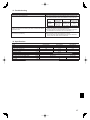
12. Specifications
Model
Power source (voltage <V>/Frequency <Hz>)
Rated Input (Indoor only)
Rated Current (Indoor only)
Heater
Dimension (Height)
Dimension (Width)
Dimension (Depth)
Fan airflow volume (Low-Middle-High)
Noise leve (Low-Middle-High)
Net weight
PKA-A24KA(L)
<kW>
<A>
<kW>
<inch>
<inch>
<inch>
<CFM>
<dB>
<lbs>
0.05
0.36
–
PKA-A30KA(L)
Single 208/230, 60
0.05
0.36
–
14-3/8
46-1/16
11-5/8
635-705-775
39-42-45
46
PKA-A36KA(L)
0.08
0.57
–
705-810-920
43-46-49
17
Please be sure to put the contact address/telephone number on
this manual before handing it to the customer.
HEAD OFFICE: TOKYO BLDG., 2-7-3, MARUNOUCHI, CHIYODA-KU, TOKYO 100-8310, JAPAN
RG79D424H01
Printed in Thailand