1
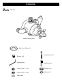
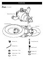
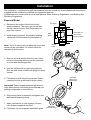
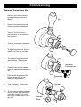
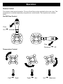
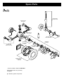
Installation, Operating and
Maintenance Guide
Part no. 800040-B
Contents
Exposed
Shower Mixing Valve
Wall Cover Plate (x2)
Strainer (x2)
Fixing Screw (x2)
Hexagon Key
Wall Plug (x2)
Green Limiter - 7 litre
Retainer (x2)
Yellow Limiter - 5 litre
Washer (x2)
Orifice disc
Contents
Concealed
Shower Mixing Valve
Concealing Plate
Wall Plate
Wall Seal
Strainer (x2)
Fixing Screw (x8)
Hexagon Key
Wall Plug (x8)
Green Limiter - 7 litre
Retainer (x2)
Yellow Limiter - 5 litre
Washer (x2)
Orifice disc
Introduction
When A & J Gummers began production in 1861, ’Victorian’ was up to the minute design.
During 150 years of unbroken production, the company has constantly expanded the
boundaries of water technology to become one of the leading British shower manufacturers.
Technological evolution from Gummers means that all the Renaissance range will work with most
plumbing systems, including unbalanced pressures, combi boilers/high pressure systems and low
pressure systems, in certain low pressure systems it is recommended that a pump is fitted to ensure
maximum satisfaction can achieved.
Hiding behind this elegant Renaissance designs, are the most up to date, thermostatic and ceramic
disc technologies. The fusion of old and new enables a warming beauty that flows from within, to be
enjoyed by the youngest to the oldest safely.
In short, by looking to the past for inspiration we have developed a range for your future aspirations.
Description
The multi-functional Duellé thermostatic available as exposed or concealed fitting, in a choice of
chrome or antique gold. With separate controls for temperature and flow gives the user total control.
The Duellé ½" thermostatic dual lever mixer incorporates a wax temperature sensing capsule which
provides almost immediate repsonse to pressure and temperature changes of the incoming water
supplies to maintain the selected temperature.
The mixer has hot and cold inlet connections, with integral checkvalves fitted and a top or bottom
outlet option for rigid or flexible shower fittings.
Designation
Thermostatic mixing valve ½" (DN15*), without divertor, visible and concealed, moveable or fixed
outlet, shower, vertical mounting.
* Note! DN15 is the Australian nominal size designation, adaptors are available to convert inlets or
outlet to comply with AS 3688.
Specification
General
The installation, commissioning and maintenance must be carried out in accordance with instructions
supplied and be installed by qualified and competent persons.
Installations must comply with all Local and National Water Authority Regulations, and Building and
Plumbing Regulations.
Temperature Control
Minimum cold water supply temperature: 5°C
Maximum cold water supply temperature: 20°C
Maximum hot water supply temperature: 85°C
(a temperature of 60-65°C is recommended for ablutionary installations)
Note! A suitable hot water temperature control device should be installed to reduce temperatures
exceeding the above maximum hot water supply temperature.
Minimum temperature differential between hot supply and outlet temperature: 10°C
(eg. shower temperature 43°C: minimum hot supply 53°C)
Factory pre-set temperature: 43°C
Thermostatic control range: 38-45°C
Operating pressures
Minimum dynamic pressure (gravity): 0.1 bar (10 kPa) or 1 metre head of water
Maximum dynamic pressure (mains): 6.0 bar (600 kPa)
Maximum static pressure: 10 bar (1000 kPa)
Maximum pressure differential: 5:1 (either supply) eg. Cold 1 bar (100 kPa): Hot 0.2 bar (20 kPa)
For optimum performance, supply pressures should be equal.
Note! A suitable pressure control device should be installed to reduce supply pressures exceeding
the above maximum pressure specification (see Compatible Systems).
Flow Performance
Flow rates are open outlet with equal pressures
Pressure Loss (bar)
0.1 0.2 0.3 0.4 0.6 0.8 1.0 1.5 2.0
Pressure Loss (kPa)
10
20
30
40
60
80
100 150 200
Flow Rate (litres/minute) 11
16
18
20
25
29
33
40
46
Dimensions
Exposed
165mm
175mm
34mm
138-145mm
172mm
Connections: G½B supplied with 15mm compression fitting
Concealed
205mm
26mm
66±10mm
160mm
165mm
Connections: G½B supplied with 15mm compression fitting
Compatible Systems
Instantaneous heated system
Key
Shower inc. non-return valves
Isolating valve
Tempering valve
Pressure regulating valve
Strainer
Expansion vessel (optional)
Gravity fed system
Pumped system
1 metre
Head
Min.
Unvented mains pressure system
System includes:
Expansion vessel
Pressure relief valve
Temperature relief valve
Pressure reducing valve
Energy cut-outs
Mains pressurised hot water system
Application Selection Table
For optimum performance from the thermostatic mixing valve, use the table to match the supply
system to the mixing valve. The table gives recommendations for flow limiter selection and bottom
cap adjustment.
Flow Limiter
Supply System
Cold Supply
Hot Supply
Cold
Hot
Comments
0.1 to 1.0 bar
0.1 to 1.0 bar
No
No
Maximum pressure
loss ratio 5:1
1 to 5 bar
or Pumped
1 to 5 bar
or Pumped
Green
(7 litre)
Yellow
(5 litre)
# Use arrangement
for pumped system
Gravity 0.1 to 0.2 bar
White
Disc
No
Gravity 0.2 to 0.5 bar
Green
(7 litre)
No
Green
(7 litre)
Yellow
(5 litre)
Instantaneous
Gas Water Heater
Green
(7 litre)
*Yellow
(5 litre)
**Instantaneous
Electric Water Heater
Green
(7 litre)
No
Gravity above 0.5 bar
Mains
1.5 to 10 bar
Unvented Mains
Pressurised
# Limiters can be fitted if water economy is required.
* Yellow (5 litre) limiter may not be necessary on some gas heaters.
** IMPORTANT! -It is a requirement of Instantaneous Electric Water Heaters that a stable flow of water passes through
the heater.
This requirement can be satisfied by using a flow stabiliser fitted prior to the heater and should be adjusted to give a
temperature of between 45-50°C from the heater.
Fitting limiter or orifice disc
Inlet elbow
Green - 7 litre
Yellow - 5 litre
White orifice disc
Retaining
ring
Washer
Limiter or
orifice disc
Installation
The installation, commissioning and maintenance must be carried out in accordance with instructions
supplied and be installed by qualified and competent persons.
Installations must comply with all Local and National Water Authority Regulations, and Building and
Plumbing Regulations.
Exposed Model
1. Determine the routes of the hot and cold
supply pipework. The mixer can be fed from
the top, rear or bottom. See Dimensions for
pipe inlet centres.
2. Install supply pipework. Accessible isolating
valves are recommended for maintenance.
Note! Try fit of mixing valve to pipework, each inlet
elbow can be unscrewed 1½ turns to allow for
adjustment and location.
Top Inlets
Inlet pipes cut
16mm from
centre of mixer.
Rear
Inlets
Bottom
Inlets
3. Remove the wall bracket from the rear of the
mixer by loosening retaining on the underside
of mixer with the hexagon key.
4. Use the wall bracket to mark hole positions.
Drill wall and insert suitable wall plugs for fixing
screws.
Inlet pipe
16mm from
wall surface
5. Fit bracket to wall using fixing screws. Ensure
retaining hole for grubscrew is at the bottom.
Important! Ensure supply pipework is flushed to
clear debris before connecting mixer. Do not use
sealing compounds on connections.
6. Offer mixing valve to pipework and tighten the
wall bracket retaining screw.
7. Make connections to inlet supplies. Ensure
inlet strainers supplied are fitted.
8. Fit shower kit, see separate installation guide.
Wall plate
(rear inlet only)
Strainer
Installation
Concealed Model
Optional inlets
and outlet
Mix Outlet
1. Determine the routes of the pipework. The
mixer can be fed from the top or bottom. See
Dimensions for pipe inlet centres.
2. Channel wall to correct depth to accept mixer,
the depth for mixer is 80mm to finished wall
surface.
3. Install supply and outlet pipework, the outlet
may be a fixed shower head or a wall outlet
elbow (see shower kit).
Note! Try fit of mixing valve to pipework, each inlet
elbow can be unscrewed 1½ turns to allow for
adjustment and location.
Hot Inlet
Cold Inlet
Wall Bracket
3. Remove the wall bracket from the rear of the
mixer by loosening retaining on the underside
of mixer with the hexagon key.
4. Use the wall bracket to mark hole positions.
Drill wall and insert suitable wall plugs for fixing
screws.
5. Fit bracket to wall using fixing screws.
Important! Ensure supply pipework is flushed to
clear debris before connecting mixer.
6. Offer mixing valve to pipework and tighten the
wall bracket retaining screw.
7. Make connections to inlet supplies. Ensure
inlet strainers are fitted. Make connection to
outlet pipework and shower fitting.
Important! Serviceable access to the unit should
be provided for future adjustment and
maintenance.
Note! Remove Lever
Wall Seal
8. Finish wall surface, mark fixing holes on wall
plate, drill and fit suitable wall plugs.
Note! The flow control lever will need to be
removed to fit plate.
9. Fix fit wall seal, wall plate to wall. Fit the
concealing plate to wall plate, the plate has to
be rotated 45° from slots to fix in position.
Wall Plate
Concealing Plate
Commissioning
Maximum Temperature Stop
1.
Remove the centre indice to
reveal retaining screw and
washer.
2.
Remove the retaining screw
using a suitable screwdriver.
3.
Turn the flow control fully
anticlockwise to the maximum
flow position.
4.
Turn the temperature handle to
the maximum hot position.
5.
To adjust temperature, pull the
handle out 5mm, to override
stop.
6.
To increase temperature turn
anticlockwise. To decrease
temperature turn clockwise.
7.
Flow
Control
Increase
Temperature
Carefully remove the handle
once the desired temperature is
set.
5mm
8.
Refit handle stop against the
internal screw stop to set
maximum temperature.
9.
Turn off shower. Refit screw,
washer and indice.
10. To check thermostatic response,
run the shower and isolate the
cold water supply. The outlet
flow should cease within a few
seconds.
Decrease
Temperature
Screw
Stop
Handle
Stop
Operation
Shower Control
The shower is dual control operation. The on-off and flow can be controlled by the outer lever. The
temperature is controlled separately using the inner crutch handle. The sequences are outlined
below:
On-Off Flow Control
Flow
On
➟ Increase
Flow
Decrease
➟ Off
Temperature Control
Cold
➟ Tepid
Tepid
➟ Hot
Hot
➟ Maximum
Fault Finder
Fault
Cause
Rectification
No or reduced flow and/or fluctuating
temperature.
- Shower head blocked.
- Isolating valve partially closed.
- Instantaneous boiler cycling on
and off as flow rate/pressure too
low.
- Shut-off setting incorrect.
- Gravity head of water below
minimum required.
- Blockage in supplies/mixing valve.
- Clear debris from shower head.
- Open valve.
- Adjust bottom cap setting.
Check boiler settings are correct.
Contact boiler manufacturer.
- Turn off shower until flow
ceases, reposition lever
- Raise tank or fit pump.
- Dismantle and check for debris.
Flush supplies before refitting.
- Do not use other draw offs whilst
showering.
- See maximum pressure
differential in Specifications.
- Check Application Selection.
- Check System Requirements for
correct installation method.
- Check non return valves and
condition of seals.
- Other draw offs in use causing
pressure or temperature changes.
- Supply pressures unequal.
- Flow limiters incorrectly fitted.
- Air lock in system.
- Shower cross circulating.
Maximum outlet temperature too hot
or too cold.
- Maximum temperature incorrectly
set.
- Reset maximum temperature.
Refer to Instructions.
Maximum temperature too cold or
runs cold after a short time
(maximum temperature set or fully
adjusted).
- Hot water is less than 10°C above
the outlet temperature required.
- Adjust tank temperature to
60-65°C.
Ensure hot water is up to
temperature.
- Check tank or heater capacities.
Low capacity equals shorter
showering time.
- Increase flow through system.
Increase pressure in system.
Check for blockages.
Contact boiler manufacturer.
- Insufficient hot water supply or
storage (running out of hot water).
- Instantaneous boiler not igniting as
water flow rate/pressure too low.
Outlet flow too much.
- Flow limiters incorrectly fitted.
- Check Application Selection.
Only hot or cold water at outlet
- Inlet supplies reversed/backwards.
- Ensure supplies are connected
correctly to hot and cold inlets.
- Clean out debris.
- Inlet supplies blocked.
Shower will not shut off or leaking
from body.
- Seal damage or wear.
- Scale build up inside mixer.
- Inlet pressures above maximum
recommendations.
- Renew all seals.
- Dismantle and check for debris.
- Ensure supply pressures are
within Specification.
Fit pressure regulating valve if
necessary.
No thermostatic fail safe.
- Inlet temperatures not within
specification.
- Check inlet temperatures, hot
supply should be 10°C higher
than shower outlet temperature.
- Dismantle and check for debris.
- Replace thermostat.
- Dismantle and check for debris.
- Ensure supplies are connected
correctly to hot and cold inlets.
-
Piston assembly jammed.
Thermostat failure.
Debris trapped in mechanism.
Inlet supplies reversed.
Care and Maintenance
Cleaning
5. Access to the thermostat (10), piston
assembly (11) and return spring (12), once
the head assembly has been removed.
Disassemble Head
Many household cleaners contain abrasive and
chemical substances, and should not be used
for cleaning plated or plastic fittings.
These finishes should be cleaned using a mild
washing up detergent or soap solution, rinsed
with clean water and wiped dry with a soft cloth.
Routine Maintenance
The frequency and extent of attention required
will vary according to prevailing site and
operational conditions, however a 12 monthly
maintenance schedule is recommended.
If the shower mixer has operated satisfactorily
for some time, but performance has has been
degraded, please check the Fault Finder
section to identify the problem.
Maintenance Check list
Worn or damaged seals and washers
Damaged seal faces
Thread wear
6. Remove circlip (4) and push spindle (8)
downward.
7. Remove spindle from spindle housing (9).
8. Turn flow nut (3) clockwise until the valve
head assembly can be removed.
9. Using suitable cirlip pliers remove circlip (1)
and remove the flow nut (3).
10. Using a suitable flat tool, at least 4mm thick,
inserted thru slots in half cartridge (7) and a
spanner 32mm A/F on flow adjust head (5),
unscrew items (5,6,7).
11. Remove all seals and washers and soak
metal components in a kettle descalent,
following descalent manufacturers
instructions.
12. Replace worn or damaged seals or
washers.
13. Ensure seals are fitted to their respective
components. Grease seals and
components marked thus .
Incorrect adjustment
Component failure
Note! Half cartridge (7) must be assembled to
flow adjust head (5) using anaerobic thread
retainer suitable for potable water.
Debris or limescale build-up
14. Reassemble the components. Assembly is
reversal of the dismantling sequence.
Service Guide
1. Isolate hot and cold supplies.
2. Remove ceramic indice from the control
knob.
3. Remove retaining screw from centre,
remove control knob, lever and sleeve.
4. Using a spanner 45mm A/F on the flats of
the head (2), unscrew anticlockwise and
remove.
Important! To set the flow control correctly,
remove the temperature control. Open valve
until water flows, turn lever off until flow is
completly shut off. Remove lever and re-fit in
the vertical or 12 o’clock position. Refer to
Commissioning section to re-set temperature.
Spare Parts
SK1500-8##
Antique Lever
SK1500-11##
Wall plates
*
*
SK1500-12
Flow Limiter
12
*
*
*
SK1850-14##
Knob Assembly
11
*
10
SK1500-3
Thermostat
& Piston
SK1500-9##
Elbow Assembly
9
SK1850-2
Cartridge
8
*
SK1850-16
Spindle
*
7
*
6
5
4
*
3
*
*
*
2
*
*
1
*
*
SK1850-15##
Concealing
Plate Kit
* Items included in Seal Kit: SK1850-1
## Denotes finish: CP (chrome)
GP (gold)
Denotes: grease component
*
*
Product Support
Guarantee
This product is guaranteed against faulty materials and workmanship for 12 months from date of purchase. For the
guarantee to be valid, the unit must be installed by a competent person, in accordance with the instruction booklet.
Any part found to be defective during the guarantee period, will (at our option) be repaired or replaced, free of charge,
provided the unit has been installed, and properly used in accordance with the instruction booklet.
This guarantee does not affect your statutory rights.
Service Policy (Available in UK and ROI only)
In the event of a product or component fault, firstly follow the fault finding procedure to ensure the difficulty can be
resolved.
If the fault can not be identifed using the procedure, call the installer to check installation is correct.
Failing this, please contact the Customer Service Department on telephone number below.
Have following information prepared, to help identify the product:
Model type, Date of purchase, unit serial number (if available).
The Customer Service Department will attempt to diagnose the cause of the fault and advise the necessary action to
resolve the problem over the phone.
If the fault can not be resolved and a service call is required, a Site Visit Request form will be sent to you to complete and
return.
Where applicable a fixed fee payment for parts and/or labour will be levied. The cost incurred and payment methods will
be advised over the phone and on the Site Visit Request form.
A completed form, along with payment (if applicable) must be received before the Service Callout can be arranged.
If the problem is not product related or is a component not of our manufacture, a fixed fee will be made to cover Site Visit
costs. Additional costs for parts used to rectify the non-product related problem may be imposed.
During the visit, yourself or a responsible person should be present at all times. Charges will be made if the Service
Engineer or Agent can not gain site access at the prearranged time.
Ensure water and/or electricity supplies have adequate isolation to the unit. If the unit is concealed, serviceable access
should maintained. If servicing difficulties arise from not making the provisions detailed, additional time related costs or a
recall charge will be imposed.
✆
A & J Gummers Limited
Unit H, Redfern Park Way,
Tyseley, Birmingham. B11 2DN
England
Agent:
Tel: +44 (0)121 706 2241
Fax:+44 (0)121 706 2960
Email: [email protected]
Web page: www.gummers.co.uk
The company reserve the right to alter product specifications without prior notice.