Download rotary converter – rt range installation & operating instructions
Transcript
TRANSWAVE Sales, Service and Support
Tel – 0121 7084522
Switchboard – 0121 7082811: Fax – 0121 7654054
E-mail: [email protected]
www.powercapacitors.co.uk
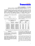
ROTARY CONVERTER – RT RANGE
INSTALLATION & OPERATING INSTRUCTIONS
Adequate overload protection for both the driven machinery and the supply circuit to the
converter is the responsibility of the customer. The customer should also ensure that the
electricity system and cable supplying the converter is of sufficient capacity to allow the
motor to start without causing undue supply disturbances as a consequence of voltage drop.
THE CUSTOMER MUST ENSURE THAT THE OUTPUT NEUTRAL FROM THE CONVERTER IS NOT
CONNECTED TO THE ELECTRICITY PROVIDER’S SUPPLY NEUTRAL OR THE SUPPLY NEUTRAL
FROM A GENERATOR. THE SINGLE PHASE SUPPLY NEUTRAL MUST BE KEPT ELECTRICALLY
SEPARATE FROM THE CONVERTER OUTPUT NEUTRAL TO AVOID DAMAGING THE CONVERTER.
1) Ensure that the details on the converter rating plate are compatible with the electricity
supply system and the required motor loads.
2) The incoming supply should be connected to the converter via an isolator and protection
device (i.e. Fuse or Type C “motor rated” circuit breaker). Recommended fuse ratings and cable
sizes are indicated below. The output from the converter takes the form of a three-phase
neutral and earth socket (Notation: L1, L2, L3, and N). All earth connections should be securely
connected to a good earth point. Removal of the socket will compromise any warranty offered
by the manufacturers.
ROTARY CONVERTER RATINGS
CYCLIC LOAD
Minimum Load
No minimum
No minimum
No minimum
No minimum
No minimum
No minimum
No minimum
No minimum
Maximum Load
Single Motor
3.00kW/04.0hp
4.00kW/05.5hp
5.50kW/07.5hp
7.50kW/10.0hp
11.0kW/15.0hp
15.0kW/20.0hp
15.0kW/20.0hp
18.5kW/25.0hp
SINGLE PHASE SUPPLY VOLTAGE
220/240 VOLT
Fuse
Maximum Load
Circuit
Multi Motor
Breaker Cable*
3.00kW/04.0hp
25A
4.0mm
4.00kW/05.5hp
25A
4.0mm
5.50kW/07.5hp
30A
4.0mm
7.50kW/10.0hp
40A
6.0mm
11.0kW/15.0hp
60A
10.0mm
15.0kW/20.0hp
80A
16.0mm
18.5kW/25.0hp
100A
25.0mm
22.0kW/30.0hp
120A
25.0mm
*Minimum size for run of up to 20m.
For longer cable runs see current edition of BS7671/AS300 amendment 2.
3) The RT converter incorporates a rotary transformer, which establishes the artificial threephase output from the converter when energised.
4) Before any machinery is connected to the output of the converter, switch the converter on
by using the ‘ON’ button located on the converter. The converter will automatically attain its
full operating speed within a few seconds.
POWER CAPACITORS LIMITED
30 REDFERN ROAD
TYSELEY
BIRMINGHAM
B11 2BH
1q
BS EN ISO 9001 Certificate No. 8174
The initial surge required to start the motor is provided by the boost circuit of the converter.
The “boost on” light indicates the circuit is energised. The circuit is controlled automatically
from within the converter, switching on whenever a motor is starting against load and switching
off once the motor has attained its full running speed. If the boost light does not go out within a
few seconds the converter should be switched off to avoid the possibility of electrical damage.
The reason for this condition should be checked and corrected before the converter is restarted.
5) Note that if voltages were checked at this point phase to phase readings would be similar to
those experienced on a mains three-phase supply. Note that the voltages do not relate to
earth as they would on a mains three-phase supply. Switch the converter off and connect
driven machines to the converter output socket.
Care should be taken with the connection of the machine to the output socket. If the
machine has a contactor starter the 400/415v-control coil must be fed from the phases
marked L1 and L2. If the control circuit is fed incorrectly (i.e. connected to the phase
marked L3) the contactor could chatter when operating. Similarly, a control transformer
and/or lighting transformer with a primary winding of 415v must be fed from the L1 and L2
phases. Connection to the L3 phase could lead to premature ageing of the control
transformer. The RT converter can accommodate both a 415v control circuit (as above) and
a single phase 240v control circuit provided the L1 phase is used in conjunction with the
output Neutral. Multi-motor applications should be supplied from the converter output via a
three-phase radial or similar. Note that the output neutral is for control circuit loads only. It
should not be connected to any single-phase inductive or resistive loads.
If the rotation of the driven machine motor is incorrect, ensure that the converter phases
marked L1 and L2 are changed for 415-volt phase-phase control circuitry. For 240-volt phaseneutral control circuitry, ensure that the phase-neutral supply is maintained and the other two
phases reversed.
The motor starting current is limited to approximately three times the full load current of the
motor. The starting characteristics of a three-phase motor supplied by a converter are similar
in nature to Star/Delta starting on a three-phase system. Significant reductions in starting
torque are experienced when compared with direct on line starting on a three-phase supply.
For machinery supplied by a converter, direct-on-line starting is recommended. For machinery
fitted with Star/Delta starters, the period in the star connection should be as short as possible
to ensure a successful start.
6) An over-temperature sensor protects the converter. If the converter trips out on overtemperature, the output supply lamp will go off. The converter will not restart until it has
sufficiently cooled. Checks should be carried out to ascertain why the converter has overheated,
before restarting.
NOTE - The output from a TRANSWAVE Converter cannot be compared directly to a mains threephase electricity supply. The TRANSWAVE Converter offers an artificial means by which a threephase motor (or motors) can be operated from a single-phase electricity supply. The
TRANSWAVE Converter cannot be made to work equally on all motors, even though the
horsepower, speed and voltage ratings are the same. Motors of differing manufacture and
motors designed for differing applications vary considerably in their electrical characteristics. It
is not always possible to make a universally applicable converter to operate a motor of given
horsepower and rating. TRANSWAVE Converters are not designed for use in conjunction with
continuous duty applications.
© Power Capacitors Limited 05/2002


