1
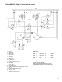
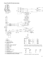
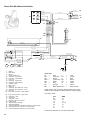
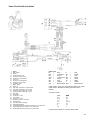
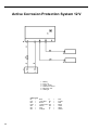
Workshop Manual
Wiring diagram
A
2(0)
MD2010, MD2020, MD2030, MD2040
MD22, TMD22, TAMD22
Grupp 30 Electrical system
Wiring diagram
MD2010A/B/C/D, MD2020A/B/C/D
MD2030A/B/C/D, MD2040A/B/C/D
MD22A, MD22L-B, MD22P-B
TMD22A, TMD22-B, TMD22P-C
TAMD22P-B
Contents
Safety Information ......................................... 2
General Information....................................... 5
Wiring diagram ............................................... 6
Engine 2010 - 2040A ........................................ 6
Engine 2010 - 2040B/C/D ................................ 8
Engine MD22A - TAMD22P-B ......................... 10
Instrument panel with ignition switch (option 1) . 12
Instrument panel with ignition switch (option 2) 14
Instrument panel with starter button .................. 16
Instrument kit .................................................... 18
Diode cable ..................................................... 20
SX Power Trim ................................................ 22
Active anti-corrosion system ........................... 28
............................................................................
............................................................................
............................................................................
............................................................................
1
Safety information
Introduction
This Workshop Manual contains technical data, descriptions and repair instructions for Volvo Penta products or product versions contained in the contents list.
Ensure that the correct workshop literature is being
used.
Read the safety information and the Workshop Manual “General Information” and “Repair Instructions” carefully before starting work.
Check that the warning or information decals on
the product are always clearly visible. Replace
decals that have been damaged or painted over.
Never start the engine without installing the air
cleaner (ACL). The rotating compressor in the turbocharger can cause serious personal injury. Foreign objects entering the intake ducts can also
cause mechanical damage.
Important
In this book and on the engine you will find the following
special warning symbols.
WARNING! If these instructions are not followed
there is a danger of personal injury, extensive damage to the product or serious mechanical malfunction.
IMPORTANT! Used to draw your attention to something that can cause damage, product malfunction or damage to property.
NOTE! Used to draw your attention to important information that will facilitate work or operations.
Below is a summary of the risks and safety precautions
you should always observe or carry out when operating
or servicing the engine.
Immobilize the engine by turning off the power
supply to the engine at the main switch (switches) and lock it (them) in the OFF position before starting work. Set up a warning notice at the
engine control point or helm.
Never use start spray or similar to start the engine. The starter element may cause an explosion
in the inlet manifold. Danger of personal injury.
Avoid opening the coolant filler cap when the engine is hot. Steam or hot coolant can spray out.
Open the coolant filler cap carefully and slowly to
release pressure before removing the cap completely. Take great care if a cock, plug or engine
coolant line must be removed from a hot engine.
It is difficult to anticipate in which direction steam
or hot coolant can spray out.
Hot oil can cause burns. Avoid skin contact with
hot oil. Ensure that the lubrication system is not
under pressure before commencing work on it.
Never start or operate the engine with the oil filler
cap removed, otherwise oil could be ejected.
Stop the engine before carrying out operations on
the engine cooling system.
Generally, all servicing should be carried out with
the engine switched off. Some work (carrying out
adjustments for example) requires that the engine is running. Approaching a running engine is
dangerous. Loose clothing or long hair can fasten
in rotating parts and cause serious personal injury. If working in proximity to a running engine, careless movements or a dropped tool can result in
personal injury. Avoid burns. Take precautions to
avoid hot surfaces (exhausts, turbochargers,
charge air pipes and starter elements etc.) and
liquids in supply lines and hoses when the engine is running or has been turned off immediately
prior to starting work on it. Reinstall all protective
parts removed during service operations before
starting the engine.
2
Start the engine only in a well-ventilated area. If
operating the engine in an enclosed space, ensure that exhaust gases are ventilated out of the
working area.
Always use protective goggles where there is a
danger of pieces of metal, sparks from grinding,
acid or other chemicals being thrown into your
eyes. Your eyes are very sensitive, injury can
lead to loss of sight!
Avoid skin contact with oil. Long-term or repeated
contact with oil can remove the natural oils from
your skin. The result can be irritation, dry skin,
eczema and other skin problems. Used oil is
more dangerous to health than new oil. Use protective gloves and avoid using oil-soaked clothes
and rags. Wash regularly, especially before meals. Use the correct barrier cream to prevent dry
skin and to make cleaning your skin easier.
Most chemicals used in products (engine and
transmission oils, glycol, petrol and diesel oil)
and workshop chemicals (solvents and paints)
are hazardous to health Read the instructions on
the product packaging carefully! Always follow
safety instructions (using breathing apparatus,
protective goggles and gloves for example). Ensure that other personnel are not unwittingly exposed to hazardous substances (by breathing
them in for example). Ensure that ventilation is
good. Handle used and excess chemicals according to instructions.
Be extremely careful when tracing leaks in the
fuel system and testing fuel injection nozzles.
Use protective goggles! The jet ejected from a
fuel injection nozzle is under very high pressure,
it can penetrate body tissue and cause serious
injury There is a danger of blood poisoning.
All fuels and many chemicals are inflammable.
Ensure that a naked flame or sparks cannot ignite fuel or chemicals. Combined with air in certain
ratios, petrol, some solvents and hydrogen from
batteries are easily inflammable and explosive.
Smoking is prohibited! Ensure that ventilation is
good and that the necessary safety precautions
have been taken before carrying out welding or
grinding work. Always have a fire extinguisher to
hand in the workplace.
Store oil and fuel-soaked rags and fuel and oil filters safely. In certain conditions oil-soaked rags
can spontaneously ignite. Replaced fuel and oil
filters are environmentally harmful waste and
should be disposed of at proper disposal areas
together with engine and transmission oil, contaminated fuel, old paint, degreasing agents, and
cleaning residue.
Never allow a naked flame or electric sparks near
the batteries. Never smoke in proximity to the
batteries. The batteries give off hydrogen gas
during charging which when mixed with air can
form an explosive gas - oxyhydrogen. This gas is
easily ignited and highly volatile. Incorrect connection of the battery can cause a spark which is
sufficient to cause an explosion with resulting damage. Do not disturb battery connections when
starting the engine (spark risk) and do not lean
over batteries.
Never interfere with the terminals when the system is operative. A high energy pulse may be generated which will damage the electrical system.
Never mix up the positive and negative battery
terminals when installing. Incorrect installation
can result in serious damage to electrical equipment. Refer to wiring diagrams.
Always use protective goggles when charging
and handling batteries. The battery electrolyte
contains extremely corrosive sulfuric acid. If this
comes into contact with the skin, wash immediately with soap and plenty of water. If battery acid
comes into contact with the eyes, immediately
flush with copious amounts of water and obtain
medical assistance.
Turn off the engine and turn off power at main
switch(es) before carrying out work on the electrical system.
Clutch adjustments must be carried out with the
engine turned off.
Use the lifting eyes mounted on the engine when
lifting the drive unit. Always check that lifting
equipment is in good condition and has sufficient
load capacity to lift the engine (engine weight including any extra equipment installed).
To ensure safe handling and to avoid damaging
engine components on top of the engine, use a
lifting beam to raise the engine. All chains and
cables should run parallel to each other and as
perpendicular as possible in relation to the top of
the engine.
If extra equipment is installed on the engine altering its center of gravity, a special lifting device is
required to achieve the correct balance for safe
handling.
Never carry out work on an engine suspended on
a hoist.
3
Säkerhetsinformation
Never remove heavy components alone, even
where secure lifting equipment such as secured
blocks are being used. Even where lifting equipment is being used it is best to carry out the work
with two people; one to operate the lifting equipment and the other to ensure that components
are not trapped and damaged when being lifted.
The components in the electrical system and in
the fuel system on Volvo Penta products are designed and manufactured to minimize the risk of
fire and explosion. The engine must not be run in
areas where there are explosive materials.
Always use fuels recommended by Volvo Penta.
Refer to the Instruction Book. The use of lower
quality fuels can damage the engine. On a diesel
engine poor quality fuel can cause the control rod
to seize and the engine to overrev with the resulting risk of damage to the engine and personal
injury. Poor fuel quality can also lead to higher
maintenance costs.
Säkerhetsinformation
4
General information
About the workshop manual
•
This workshop manual contains technical data, descriptions and repair instructions for standard versions of the
engine units.
•
This Workshop Manual has been developed primarily
for Volvo Penta service workshops and qualified personnel. Persons using this book are assumed to have a
grounding in the repair and service of diesel engines
and be able to carry out related mechanical and electrical work.
Volvo Penta is continuously developing their products.
We therefore reserve the right to make changes. All the
information contained in this book is based on product
data available at the time of going to print. Any essential changes or modifications introduced into production
or updated or revised service methods introduced after
the date of publication will be provided in the form of
Service Bulletins.
•
The engine must not be modified in any way apart
from with accessories and service kits developed for
it by Volvo Penta.
No modifications to the exhaust pipes and air supply
ducts may be undertaken as this may effect exhaust
emissions.
Seals may only be broken by authorized personnel.
IMPORTANT! Use only Volvo Penta Genuine
Parts. Use of non-original AB Volvo Penta spare
parts will result in AB Volvo Penta being unable
to assume liability for the engine meeting engine certification requirements. No damage and
costs caused by the use of non-genuine replacement parts will be paid by Volvo Penta.
Replacement parts
Replacement parts for electrical and fuel systems are
subject to statutory requirements (US Coast Guard Safety Regulations for example). Volvo Penta Genuine
parts meet these requirements. Any type of damage
which results from the use of non-original Volvo Penta
replacement parts for the product will not be covered
under any warranty provided by Volvo Penta.
Certificated engines
Engines certificated to meet national and regional environmental legislation carry with them an undertaking
from the manufacturer that both new and existing engines in use meet the environmental demands of the legislation. The product must be the same as the example approved for certification purposes. So that Volvo Penta, as a manufacturer, can guarantee that currently operational engines meet environmental
regulations, the following service and replacement part
requirements must be observed:
•
•
•
The Service Intervals and maintenance operations
recommended by Volvo Penta must be observed.
Only Volvo Penta genuine replacement parts, intended for the certificated engine, may be used.
The servicing of injector pumps, pump settings and
injectors must always be carried out be an authorized Volvo Penta workshop.
5
Engine
MD2010A–2040A
1,5-pole* electrical system
* 1 pole during the start and stop phases, 2 pole at all other times.
6
Engine MD2010–2040A (1.5-pole electrical system)
1.
2.
3.
4.
5.
6.
7.
8.
9.
10.
11.
12.
13.
14.
15.
16.
17.
18.
Battery
Main switch
Starter motor
Ground relay
Ground rail
Glow plugs*
Generator
Starter relay
Glow plug relay
Protective diode**
Fuses (x4), maximum 15A (+)
Fuses (x4), maximum 15A (–)
Cable splice
Engine oil pressure switch (normally open, closes below
0.3 ± 0.1 bar)
Oil pressure sensor
Coolant temperature switch (normally open, closes at
95° ± 3°C)
Engine coolant temperature sensor
Connector, 16-pin
Cable color
BL
=
LBL =
BN
=
LBN =
GN
=
GR
=
OR
=
Blue
Light-blue
Brown
Light-brown
Green
Gray
Orange
P
PU
R
SB
VO
W
Y
=
=
=
=
=
=
=
Pink
Purple
Red
Black
Violet
White
Yellow
Cable cross sections in mm2 are indicated after the colour
codes in the wiring diagram.
Cable cross sections not indicated = 1.5 mm².
A dashed line indicates a non-Volvo Penta cable.
* MD2010: x 2 Other engines: x 3
** Non-standard on earlier models.
7
Engine
MD2010–2040B/C/D
1-pole electrical system
8
Engine MD2010–2040B/C/D (1-pole electrical system)
1.
2.
3.
4.
5.
6.
7.
8.
9.
10.
11.
12.
13.
14.
Battery
Main switch
Starter motor
Generator
Glow plugs
Starter relay
Glow plug relay
Fuses (x4), maximum 15 A
Charging regulator resistance 33/9 W
Engine oil pressure switch (normally open, closes below
0.3 ± 0.1 bar)
Oil pressure sensor
Coolant temperature switch (normally open, closes at
100° ± 2°C)
Engine coolant temperature sensor
Connector, 16-pin
Cable color
BL
=
LBL =
BN
=
LBN =
GN
=
GR
=
OR
=
Blue
Light-blue
Brown
Light-brown
Green
Gray
Orange
P
PU
R
SB
VO
W
Y
=
=
=
=
=
=
=
Pink
Purple
Red
Black
Violet
White
Yellow
Cable cross sections in mm2 are indicated after the colour
codes in the wiring diagram.
Cable cross sections not indicated = 1.5 mm².
A dashed line indicates a non-Volvo Penta cable.
9
Engine
MD22A, MD22L-B, MD22P-B
TMD22A, TMD22-B, TMD22P-C, TAMD22P-B
1,5-pole electrical system
* 1 pole during the start and stop phases, 2 pole at all other times.
10
Engine MD22A – TAMD22P-B (1.5-pole electrical system)
1.
2.
3.
4.
5.
6.
7.
8.
9.
10.
11.
12.
13.
14.
15.
16.
17.
18.
19.
Battery
Main switch
Starter motor
Generator
Ground relay
Fuse 55 A
Automatic fuse 8 A
Starter relay
Glow plug relay
Glow plugs (x4)
Oil pressure switch - Engine, combined
Oil pressure sensor - Engine, combined
Solenoid valve
Coolant temperature switch - Engine
Coolant temperature sensor - Engine
Automatic fuse 8 A
Resistance
Cable splice
CPC connector, 16-pin
Cable color
BL
=
LBL =
BN
=
LBN =
GN
=
GR
=
OR
=
Blue
Light-blue
Brown
Light-brown
Green
Gray
Orange
P
PU
R
SB
VO
W
Y
=
=
=
=
=
=
=
Pink
Purple
Red
Black
Violet
White
Yellow
Cable cross sections in mm2 are indicated after the colour
codes in the wiring diagram.
Cable cross sections not indicated = 1.5 mm².
A dashed line indicates a non-Volvo Penta cable.
11
Instrument panel with ignition switch (alt.1)
MD2010–2040A/B/C/D
MD22A, MD22L-B, MD22P-B
TMD22A, TMD22-B, TMD22P-C, TAMD22P-B
12
Instrument panel with ignition switch MD2010 – 2040A/B/C/D and MD22A – TAMD22P-B
Spring loaded
1.
2.
3.
4.
5.
6.
7.
8.
9.
10.
11.
12.
13.
14.
15.
16.
17.
18.
Instrument lighting
—
—
—
Connector for extra warning display (accessory)
Alarm unit
Engine coolant temperature warning lamp
Oil pressure warning lamp
Charge warning lamp
Warning lamp (not used)
Instrument lighting switch
Alarm test/acknowledgement switch
Tachometer with built-in hours run meter
Ignition switch
Alarm (buzzer)
Splice connector
CPC connector, 16-pin
Power supply 30 for the tachometer (only later models)
Spring
loaded
Cable color
BL
=
LBL =
BN
=
LBN =
GN
=
GR
=
OR
=
Blue
Light-blue
Brown
Light-brown
Green
Gray
Orange
P
PU
R
SB
VO
W
Y
=
=
=
=
=
=
=
Pink
Purple
Red
Black
Violet
White
Yellow
Cable cross sections in mm2 are indicated after the colour
codes in the wiring diagram.
Cable cross sections not indicated = 1.5 mm².
A dashed line indicates a non-Volvo Penta cable.
13
Instrument panel with ignition switch (alt.2)
MD2010–2040A/B/C/D
MD22A, MD22L-B, MD22P-B
TMD22A, TMD22-B, TMD22P-C, TAMD22P-B
14
Instrument panel with ignition switch MD2010-2040A/B/C/D and MD22A – TAMD22P-B
1.
2.
3.
4.
5.
6.
7.
8.
9.
10.
11.
12.
13.
14.
15.
16.
17.
18.
19.
Instrument lighting
Voltmeter
Oil pressure gauge
Engine coolant temperature gauge
Connector for extra warning display (accessory)
Alarm unit
Engine coolant temperature warning lamp
Oil pressure warning lamp
Charge warning lamp
Warning lamp (not used)
Instrument lamp switch
Alarm test/acknowledgement switch
Tachometer with built-in hours run meter
Ignition switch
Alarm (buzzer)
Splice connector
CPC connector, 16-pin
Connector (not used)
Power supply 30 for the tachometer (only later models)
Spring loaded
Spring loaded
Cable color
BL
=
LBL =
BN
=
LBN =
GN
=
GR
=
OR
=
Blue
Light-blue
Brown
Light-brown
Green
Gray
Orange
P
PU
R
SB
VO
W
Y
=
=
=
=
=
=
=
Pink
Purple
Red
Black
Violet
White
Yellow
Cable cross sections in mm2 are indicated after the colour codes in
the wiring diagram.
Cable cross sections not indicated = 1.5 mm².
A dashed line indicates a non-Volvo Penta cable.
15
Instrument panel with starter button
MD2010–2040A/B/C/D
16
Instrument panel with starter button MD2010 – 2040A/B/C/D
1.
2.
3.
4.
5.
6.
7.
8.
9.
10.
11.
12.
13.
14.
15.
16.
Tachometer with built-in hours run meter
Instrument lighting
Connector for extra warning display (accessory)
Alarm unit
Engine coolant temperature warning lamp
Oil pressure warning lamp
Charge warning lamp
Glow plug warning lamp
Voltage On/Off button
Start button
Alarm (buzzer)
Alarm/Glow plug rocker switch
Neutral switch connector
Semiconductor diode
CPC connector, 16-pin
Power supply 30 for the tachometer (only later models)
Cable color
BL
=
LBL =
BN
=
LBN =
GN
=
GR
=
OR
=
Blue
Light-blue
Brown
Light-brown
Green
Gray
Orange
P
PU
R
SB
VO
W
Y
=
=
=
=
=
=
=
Pink
Purple
Red
Black
Violet
White
Yellow
Cable cross sections in mm2 are indicated after the colour
codes in the wiring diagram.
Cable cross sections not indicated = 1.5 mm².
A dashed line indicates a non-Volvo Penta cable.
17
Instrument kit
MD2010–2040A/B/C/D
MD22A, MD22L-B, MD22P-B
TMD22A, TMD22-B, TMD22P-C, TAMD22P-B
18
Instrument kit
1.
2.
3.
4.
5.
6.
7.
8.
9.
10.
11.
12.
13.
14.
15.
16.
Ignition switch
Alarm test/acknowledgement switch
Instrument lighting switch
Alarm (buzzer)
Alarm unit with warning lamps for:
• Temperature
• Oil level
• Battery
• Glow plugs
Engine coolant temperature gauge
Engine oil pressure gauge
Voltmeter
Boost pressure gauge
Reverse gear oil pressure gauge
Tachometer with built-in hours run
meter
Instrument lighting
Connector, cannot be opened
9
Splice connector
CPC connector, 16-pin
Connector for extra warning display
(accessory)
Cable color
BL
=
LBL =
BN
=
LBN =
GN
=
GR
=
OR
=
P
=
PU
=
R
=
SB
=
VO
=
W
=
Y
=
Blue
Light-blue
Brown
Light-brown
Green
Gray
Orange
Pink
Purple
Red
Black
Violet
White
Yellow
19
Diode cable
MD2010–2040A/B/C/D
MD22A, MD22L-B, MD22P-B
TMD22A, TMD22-B, TMD22P-C, TAMD22P-B
1.5-pole* electrical system
* 1 pole during the start and stop phases, 2 pole at all other times.
20
Diode cable for 1.5-pole electrical system
The diode cable is necessary for the engine to be stopped electronically, using the starter switch or the stop button. The diode
cable also protects against short-circuits (cable burn out) if the battery positive terminal is unintentionally connected to the
engine body.
Outline diagram – Connection of diode kit
A. Main panel
B. Panel for alternative control position
C. Diode kit
D. Y connection
E. Central electronic module (engine)
Diode kit (C)
1. Diode
2. 16 pin CPC, to instrument panel
3. 16 pin CPC, to engine
Cable color
BL
=
LBL =
BN
=
LBN =
GN
=
GR
=
OR
=
Blue
Light-blue
Brown
Light-brown
Green
Gray
Orange
P
PU
R
SB
VO
W
Y
=
=
=
=
=
=
=
Pink
Purple
Red
Black
Violet
White
Yellow
Cable areas in mm2 are given after the color codes in the
wiring diagram.
21
Power Trim
SX-drev
Power Trim SX without trim limiter (early production)
1.
2.
3.
4.
5a.
5b.
6.
7.
8a.
8b.
9a.
9b.
10a.
10b.
11.
12.
13.
14.
15.
16.
17.
18.
19.
20.
Battery
Main switch
Starter
Circuit breaker 50 A
Connector, 2-pole male
Connector, 2-poe female
Hydraulic pump
Connector with rubber cap, 3-pole
Fully cast connectors, 3-pole female
Fully cast connectors, 3-pole male
Connector with rubber cap, 1-pole male
Connector with rubber cap, 1-pole female
Trim sender, digital
Trim sender, analouge
Connector, 7-pole
Extension cable, Y-connector
Control panel
Triminstrument, analouge
Instrument lightning
Connecting terminal, instrument lightning (+) to main panel
Connecting terminal, fuse box (–) to main panel
Connecting terminal, fuse box (+) to main panel
Circuit breaker 10 A
Circuit breaker 10 A*
Cable color
BL
=
LBL =
BN
=
LBN =
GN
=
GR
=
OR
=
Blue
Light-blue
Brown
Light-brown
Green
Gray
Orange
P
PU
R
SB
VO
W
Y
=
=
=
=
=
=
=
Pink
Purple
Red
Black
Violet
White
Yellow
Cable areas in (mm2) are given after the cable color codes.
Cable areas in brackets are AWG (American Wiring Gauge).
Conversion table:
mm2
0.5
0.75
1.0
1.5
AWG
20
18
17
15–16
mm 2
2.5
6
10
AWG
13
10
7
A broken line indicates a non-Volvo Penta cable.
* Only certain executions of SX-C1, SX-CLT1, SX-C1AC,
SX-R1 and SX-R2
23
Power Trim SX without trim limiter
late production
1.
2.
3.
4.
5a.
5b.
6.
7.
8.
9.
10a.
10b.
11.
12.
13.
14.
15.
16.
17.
18.
19.
20.
Battery
Main switch
Starter
Circuit breaker 50 A
Connector, 2-pole male
Connector, 2-poe female
Hydraulic pump
Not used
Connector, 1-pole
Connector, 3-pole
Fully cast connectors, 3-pole female
Fully cast connectors, 3-pole male
Connector 1-pole, trim by-pass
Trim sender
Extension cable, Y-connector
Connector, 7-pole
Control panel
Triminstrument, analouge
Instrument lightning
Connecting terminal, instrument lightning (+) to main panel
Connecting terminal, fuse box (–) to main panel
Connecting terminal, fuse box (+) to main panel
Cable color
BL
=
LBL =
BN
=
LBN =
GN
=
GR
=
OR
=
Blue
Light-blue
Brown
Light-brown
Green
Gray
Orange
P
PU
R
SB
VO
W
Y
=
=
=
=
=
=
=
Pink
Purple
Red
Black
Violet
White
Yellow
Cable areas in (mm2) are given after the cable color codes.
Cable areas in brackets are AWG (American Wiring Gauge).
Conversion table:
mm 2
0.5
0.75
1.0
1.5
AWG
20
18
17
15–16
mm2
2.5
6
10
A broken line indicates a non-Volvo Penta cable.
24
AWG
13
10
7
Power Trim SX, DP-S with trim limiter
1.
2.
3.
4.
5a.
5b.
6.
7.
8a.
8b.
9.
10.
11.
12.
13.
14.
15.
16.
17.
18.
19.
20.
21.
Battery
Main switch
Starter
Circuit breaker 50 A
Connector, 2-pole male
Connector, 2-pole female
Hydraulic pump
Not used
Fully cast connectors, 3-pole female
Fully cast connectors, 3-pole male
Connector, 3-pole
Connector, 1-pole
Trim limiter
Connector, 1-pole
Trim sender
Connector, 7-pole
Extension cable, Y-connector
Control panel
Trim instrument, analouge
Instrument lightning
Connecting terminal, instrument lightning (+) to main panel
Connecting terminal, fuse box (–) to main panel
Connecting terminal, fuse box (+) to main panel
Cable color
BL
=
LBL =
BN
=
LBN =
GN
=
GR
=
OR
=
Blue
Light-blue
Brown
Light-brown
Green
Gray
Orange
P
PU
R
SB
VO
W
Y
=
=
=
=
=
=
=
Pink
Purple
Red
Black
Violet
White
Yellow
Cable areas in (mm2) are given after the cable color codes.
Cable areas in brackets are AWG (American Wiring Gauge).
Conversion table:
mm 2
0.5
0.75
1.0
1.5
AWG
20
18
17
15–16
mm 2
2.5
6
10
AWG
13
10
7
A broken line indicates a non-Volvo Penta cable.
25
Power Trim SX without trim limiter
BL 1,0 (17)
21
GN 0,5 (20)
Y 0,5 (20)
22
SB 1,0 (17)
20
BN 0,5 (20)
SB 1,0 (17)
19
R/BL 1,0 (17)
GR 0,5 (20)
W 0,5 (20)
2
3
1 4
5
7
6
2
3
1 4
5
7
6
24
16
BN/W 1,5 (16)
PU/R O,75 (18)
SB 1,5 (16)
R/PU O,75 (18)
R 0,75 (18)
18
GN/W 0,75 (18)
BL/W 0,75 (18)
17
BN/BL 1,0 (17)
23
14b
A C B
11
A
W
13
SB**
15
SB*
14a
11
A C B
C
SB 1,5 (16)
BN/W 1,5 (16)
12
BL 1,5 (16)
GN 1,5 (16)
SB 6,0 (10) 87a
87
85
6
R/PU 1,5 (16)
SB 6 (10) 22-SX
SB 10 (7) 31-SX
SB 6 (10)
87a
87
R/PU 1,5 (16)
86
85
SB 1,5 (16)
BL/W 6,0 (10)
30
SB 1,5 (16)
R/PU 6,0 (10)
10
9
GN/W 6,0 (10)
30
SB 10 (7) 31-SX
SB 6 (10) 22-SX
R 6 (10) 22-SX
R 10 (7) 31-SX
R/PU 6 (10)
4
3
R 6 (10) 22-SX
R 10 (7) 31-SX
86
R/PU 6,0 (10)
R/PU 6,0 (10)
8
5b
5a
30
50
M
31-SX
31
7b 7a
GN/W
M
2
BL/W
1
1.
2.
3.
4.
5a.
5b.
6.
7a.
7b.
8.
9.
10.
11.
12.
13.
14a.
Battery
Main switch
Starter
Circuit breaker 50 A
Connector, 2-pole male
Connector, 2-pole female
Fuse 10 A
Connector, 2-pole male
Connector, 2-pole female
Hydraulic pump
Reley, down
Reley, up
Connector with rubber cap, 3-pole
Connector with rubber cap, 1-pole
Not used
Fully cast connectors, 3-pole female
14b.
15.
16.
17.
18.
19.
20.
21.
22.
23.
24.
Fully cast connectors, 3-pole male
Connector 1-pole
Trim sender
Connector, 7-pole
Extension cable, Y-connector
Control panel
Triminstrument, analouge
Instrument lightning
Connecting terminal, instrument lightning (+) to main panel
Connecting terminal, fuse box (–) to main panel
Connecting terminal, fuse box (+) to main panel
Cable color
BL
=
LBL =
BN
=
LBN =
GN
=
GR
=
OR
=
SB* =
Blue
Light-blue
Brown
Light-brown
Green
Gray
Orange
Black ribbed
P
=
PU
=
R
=
SB
=
VO
=
W
=
Y
=
SB** =
Pink
Purple
Red
Black
Violet
White
Yellow
Black smooth
Cable areas in (mm2) are given after the cable color codes.
Cable areas in brackets are AWG (American Wiring Gauge).
Conversion table:
mm2
0.5
0.75
1.0
1.5
2.5
6
10
AWG
20
18
17
15–16
13
10
7
A broken line indicates a non-Volvo Penta cable.
26
Power Trim SX with trim limiter
1.
2.
3.
4.
5a.
5b.
6.
7a.
7b.
8.
9.
10.
11a.
11b.
12.
13.
14.
15.
16.
17.
18.
19.
20.
21.
22.
23.
24.
25.
Battery
Main switch
Starter
Circuit breaker 50 A
Connector, 2-pole male
Connector, 2-pole female
Fuse 10 A
Connector, 2-pole female
Connector, 2-pole male
Hydraulic pump
Reley, down
Reley, up
Fully cast connectors, 3-pole female
Fully cast connectors, 3-pole male
Connector with rubber cap, 3-pole
Connector with rubber cap, 1-pole
Not used
Trim limiter
Connector, 1-pole
Trim sender
Connector, 7-pole
Extension cable, Y-connector
Control panel
Trim instrument, analouge
Instrument lightning
Connecting terminal, instrument lightning (+) to main panel
Connecting terminal, fuse box (–) to main panel
Connecting terminal, fuse box (+) to main panel
Cable color
BL
=
LBL =
BN
=
LBN =
GN
=
GR
=
OR
=
SB* =
Blue
Light-blue
Brown
Light-brown
Green
Gray
Orange
Black ribbed
P
PU
R
SB
VO
W
Y
SB**
=
=
=
=
=
=
=
=
Pink
Purple
Red
Black
Violet
White
Yellow
Black smooth
Cable areas in (mm2) are given after the cable color codes.
Cable areas in brackets are AWG (American Wiring
Gauge).
Conversion table:
mm 2
0.5
0.75
1.0
1.5
2.5
6
10
AWG
20
18
17
15–16
13
10
7
A broken line indicates a non-Volvo Penta cable.
27
Active Corrosion Protection System 12 V
1.
2.
3.
4.
5.
6.
Cable color
BL
=
LBL =
BN
=
LBN =
GN
=
GR
=
OR
=
28
Battery
Fuse 1 A
Active anode
Reference sensor
Electronic unit
LED light
Blue
Light-blue
Brown
Light-brown
Green
Gray
Orange
P
PU
R
SB
VO
W
Y
=
=
=
=
=
=
=
Pink
Purple
Red
Black
Violet
White
Yellow
Report form
Do you have any complaints or other comments about this manual? Please make a copy of this page, write your
comments down and post it to us. The address is at the bottom of the page. We would prefer you to write in English
or Swedish.
From: ............................................................................
......................................................................................
......................................................................................
......................................................................................
Refers to publication: .............................................................................................................................................
Publication no.: ..................................................................... Issued: ....................................................................
Suggestion/reasons: ..............................................................................................................................................
..............................................................................................................................................................................
..............................................................................................................................................................................
..............................................................................................................................................................................
..............................................................................................................................................................................
..............................................................................................................................................................................
..............................................................................................................................................................................
..............................................................................................................................................................................
..............................................................................................................................................................................
Date: ............................................................
Name: ..........................................................
AB Volvo Penta
Customer Support
Dept. 42200
SE-405 08 Gothenburg
Sweden
7740536-3 English 05-2000