1
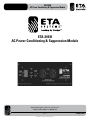
ETA-20SH
AC Power Conditioning & Suppression Module
ETA-20SH
AC Power Conditioning & Suppression Module
1601 Jack McKay Blvd. • Ennis, Texas 75119 U.S.A.
Telephone: 800-321-6699 • Fax: 800-996-3821
– 1 –
Specifications are subject to change without notice.
ETAsys.com
ETA-20SH
AC Power Conditioning & Suppression Module
TABLE OF CONTENTS
Important Safety Instructions................................................................................................................... 3
Introduction............................................................................................................................................. 5
Key Features........................................................................................................................................... 5
Applications............................................................................................................................................. 5
Internal Features...................................................................................................................................... 6
Panel Features.......................................................................................................................................... 7
Wire & Data Considerations..................................................................................................................... 8
Using the ETA-20SH as a Standalone Unit.............................................................................................. 8
ETA-20SH Remote Activation via External Switch................................................................................... 8
ETA-20SH Remote Activation External DCV............................................................................................ 8
ETA-20SH Interfaced with a ETA-ECS6RM Sequence Controller............................................................ 9
ETA-20SH Interfaced with a ETA-ECS3 Sequence Controller................................................................ 10
Mounting the ETA-20SH........................................................................................................................ 10
AC Power Cord...................................................................................................................................... 10
Troubleshooting as a Standalone Unit.................................................................................................... 11
Troubleshooting Using the ETA-20SH with a ETA-ECS3 Controller....................................................... 12
Troubleshooting Using the ETA-20SH with a ETA-ECS6RM Controller................................................. 12
AC Power Cord Retainer System........................................................................................................... 14
Specifications......................................................................................................................................... 15
Warranty................................................................................................................................................. 16
1601 Jack McKay Blvd. • Ennis, Texas 75119 U.S.A.
Telephone: 800-321-6699 • Fax: 800-996-3821
– 2 –
Specifications are subject to change without notice.
ETAsys.com
ETA-20SH
AC Power Conditioning & Suppression Module
IMPORTANT SAFETY INSTRUCTIONS
The lightning flash with arrowhead symbol within an
equilateral triangle, is intended to alert the user to the
presence of uninsulated “dangerous voltage “ within the
product’s enclosure that may be of sufficient magnitude
to constitute a risk of electric shock to persons.
The exclamation point within an equilateral triangle is
intended to alert the user to the presence of important
operating and maintenance (servicing) instructions in the
literature accompanying the product.
1. Read these instructions.
2. Keep these instructions.
3. Heed all warnings.
4. Follow all instructions.
5. Do not use this device near water.
6. Clean only with dry cloth.
7. Do not block any ventilation openings. Install in accordance with the manufacturer’s instructions.
8. Do not install near any heat sources such as radiators, heat registers, stoves, or other device (including amplifiers)
that produce heat.
9. Do not defeat the safety purpose of the polarized or grounding-type plug. A polarized plug has two blades with one wider than the
other. A grounding type plug has two blades and a third grounding prong. The wide blade or the third prong are provided for your safety. If the provided plug does not fit into your outlet, consult an electrician for replacement of the obsolete outlet.
10.Protect the power cord from being walked on or pinched particularly at plugs, convenience receptacles, and the point where they exit from the device.
11.Only use attachments/accessories specified by the manufacturer.
12.Use only with the cart, stand, tripod, bracket, or table specified by the manufacturer, or sold with the device. When a cart is used, use caution when moving the cart/device combination to avoid injury from tip-over.
13 This product is equipped with a three-wire grounding-type plug, a plug having a third (grounding) pin. This plug will only fit into a grounding-type power outlet. This is a safety feature. If you are unable to insert the plug into the outlet, contact your electrician to replace your obsolete outlet. Do not defeat the safety purpose of the grounding-type plug.
14.Unplug this device during lightning storms or when unused for long periods of time.
15.Refer all servicing to qualified service personnel. Servicing is required when the device has been damaged in any way, such as power-supply cord or plug is damaged, liquid has been spilled, or objects have fallen into the device, the device has been exposed to rain or moisture, does not operate normally, or has been dropped.
16.WARNING: To reduce the risk of fire or electric shock, this device should not be exposed to rain or moisture and objects filled with liquids, such as a vase, should not be placed on this device.
17.To completely disconnect this equipment from the mains, disconnect the power supply cord plug from the receptacle.
18.The mains plug of the power supply cord shall remain readily operable.
1601 Jack McKay Blvd. • Ennis, Texas 75119 U.S.A.
Telephone: 800-321-6699 • Fax: 800-996-3821
– 3 –
Specifications are subject to change without notice.
ETAsys.com
ETA-20SH
AC Power Conditioning & Suppression Module
•
•
•
•
•
•
•
•
•
•
•
•
•
•
•
•
•
WARNING – WHEN THE DEVICE IS IN USE
To prevent electric shock, do not remove the product cover as there are high voltage components inside. Refer all servicing to
ETA Systems.
Should any of the following irregularities occur during use, immediately switch off the power, disconnect the power cord from the AC outlet and contact ETA Systems. Do not to attempt to continue operation with the product as this may cause fire or electric shock:
• Smoke or strange smell coming from the unit.
• If the product falls or the case is damaged.
• If water or any metallic objects falls into the product.
• If the power supply cord is damaged in any way.
• If the unit is malfunctioning.
Do not insert or drop metallic objects or flammable materials into the ventilation holes of the product's cover, as this may result in electric shock or fire.
Do not place any containers with liquid or metallic objects on the top of the product. If any liquid spills into the unit, fire or electric shock may result.
Never operate this product or touch the power supply cord during an electrical storm, electric shock may result.
Never exceed the power rating on the product when connecting equipment. Fire and/or property damage may result.
Operate the product only with the voltage specified on the unit. Fire and/or electric shock may result if a higher voltage is used.
Do not modify, kink, or cut the power cord. Do not place the power cord in close proximity to heaters and do not place heavy objects on the power cord, including the product itself, doing so may result in fire or electrical shock.
Ensure that the safety ground terminal is connected to a proper ground. Never connect the ground to a gas pipe as a catastrophic disaster may result.
Be sure the installation of the product is stable, avoid slanted surfaces as the product may fall and cause injury or property damage.
CAUTION – WHEN INSTALLING THE PRODUCT
Installation of this product must be done by a certified electrician for a permanently connected apparatus provided neither with an
all-pole mains switch nor an all-pole circuit breaker. A readily accessible disconnect device shall be incorporated in the building installation power wiring. The installation shall be carried out in accordance with all applicable installation rules in accordance with all applicable federal, state, and local laws, regulations, and safety codes and ordinances.
Never install this product in humid or dusty locations, nor in direct sunlight, near sources of heat, or in areas where sooty smoke or steam are present. Fire and electric shock may result.
Keep all sides of the unit at least 31⁄2" away from objects that may obstruct air flow to prevent the unit's internal temperature rise.
CAUTION – WHEN THE DEVICE IS IN USE
Never place heavy objects on the product, causing it to fall and/or break, resulting in personal injury and property damage. In addition, the product itself may fall and cause injury and property damage.
Contact ETA Systems for instructions on cleaning the inside of the unit. Large accumulations of dust inside the unit may result in heat buildup and fire.
Ensure that the power supply plug is securely plugged into the wall outlet. Never allow dust to accumulate on the power plug or inside the wall outlet.
When cleaning the unit or the unit is not to be operated for an extended period, unplug the power cord from the wall.
1601 Jack McKay Blvd. • Ennis, Texas 75119 U.S.A.
Telephone: 800-321-6699 • Fax: 800-996-3821
– 4 –
Specifications are subject to change without notice.
ETAsys.com
ETA-20SH
AC Power Conditioning & Suppression Module
INTRODUCTION
The ETA Systems ETA-20SH is a 120V 60Hz AC Electrical Control Module (ECM), 20A Single Housing (SH) Power Conditioner and AC
Spike Suppressor that is designed to be used as a standalone unit or in conjunction with an ETA Systems Sequence controller ETAECS6RM or the ETA-ECS3 up to 1000' away.
The ETA-20SH features noise filtering for removing unwanted Radio Frequency Interference (RFI) and EMI filters to reduce noise from
Electromagnetic Interference (EMI) caused by items such as electric motors or switching power supplies. The benefit of these filters
can be seen on video products or audibly by reducing static pops and external signal interference. If an AC spike or surge appears,
the ETA-20SH also incorporates Clamping Suppression technology to prevent the unwanted energy from getting into your AV system.
Other features include a Manual Bypass Switch, Incoming AC presence LED, Active LED and an AC Fault indicator. When interfaced
with the ETA-ECS6RM Sequencer controller, Extreme Voltage Shutdown (EVS) Circuitry is active, along with Voltage and Current status
readings.
KEY FEATURES
• 2 Outlets, 20A
• RFI / EMI Noise Filtering
• Spike & Surge Suppression, DCS Circuitry
• Extreme Voltage Shutdown (EVS) Below 101V or Above 132V AC Line
• AC Fault indicator
• Fuse Protection @ 20A Slow Blow
• Manual Bypass Switch
• Incoming AC Presence LED
• Active Outlet LED
• Status Signals Output for Voltage and Current
APPLICATIONS
The ETA-20SH is designed to be flexible for use in a variety of applications. When used with a sequenced controller it allows the
turning of equipment on and off from a remote location to save energy and to reduce an in-rush of current that stresses the main AC
line. It also can be used as a standalone unit for protection against voltage surges and applies EMI/RFI filtering to clean up the AC
power at the load source. The following are just a few examples of applications in which the ETA-20SH can be used:
• Restaurants
• Houses of Worship
• Schools
• Home Theaters
• Office Buildings
• Sports Bars
• Industrial Facilities
1601 Jack McKay Blvd. • Ennis, Texas 75119 U.S.A.
Telephone: 800-321-6699 • Fax: 800-996-3821
– 5 –
Specifications are subject to change without notice.
ETAsys.com
ETA-20SH
AC Power Conditioning & Suppression Module
INTERNAL FEATURES OF THE ETA-20SH – PROTECTION BEHIND THE PANEL
• EMI/RFI Filters
ECM filters unwanted Radio Frequency Interference (RFI) that is commonly introduced into the AC lines by nearby radio
transmitters or wireless products. EMI filters are incorporated to reduce noise from Electromagnetic Interference (EMI) produced
by such items as electric motors or switching power supplies. The benefit of these filters can be seen on video products or
audibly by reducing static pops and external signal interference.
• AC Spike Protection
ECM modules feature AC spike suppression. AC Spikes, or Transients, are commonly caused by utility power plant grid
switchovers. The amount of energy that can be injected into the power system can be immense with voltages reaching 6kV or
amperage peaks of 3000A. These spikes are very fast and usually only last for a very short period of time. To protect against
this potential problem, incoming AC Mains have special suppression circuitry to eliminate the unwanted energy. This circuitry is
very fast and can suppress unwanted energy within a nanosecond, while sustaining the suppression up to 2 milliseconds, thus
ensuring virtually trouble free protection.
• AC Surge Protection
High line can also be known as surges. Surges usually are a slower steady state rise in voltages ranging from 128VAC and up.
They can be caused by fluctuations in the utility company's power lines or industrial equipment turning on and off, and are on the
same power leg of the building's incoming AC.
• EVS Protection
If an ECM Module is connected to the ETA-ECS6RM, the ETA-ECS6RM has built in intelligence that monitors the AC lines from
the ECM modules and will inform you of potentially damaging voltages. If the AC Mains voltage is between 128VAC and 132VCA
or 107VAC and 101VAC the display will flash an error code indicating a potential fault has occurred and you should check sensitive
equipment. If an extreme voltage swing occurs above 128VAC or below 101VAC, the Extreme Voltage Shutdown (EVS) protection
circuit will automatically turn all remote ECM modules off until the system is manually reset. The EVS feature can be defeated if
required via the ETA-ECS6RM EVS bypass switch.
• Over Current Protection
In the case of excessive current draw at the ECM module, an internal Slow Blow fuse will open and protect the devices plugged
in to the ECM module. Note: This fuse must be changed by a qualified service technician.
1601 Jack McKay Blvd. • Ennis, Texas 75119 U.S.A.
Telephone: 800-321-6699 • Fax: 800-996-3821
– 6 –
Specifications are subject to change without notice.
ETAsys.com
ETA-20SH
AC Power Conditioning & Suppression Module
FRONT PANEL
4
3
6
7
1
5
2
1. Trigger/Status Port Pin Identification
All signals are of low voltage and current. DO NOT MISS WIRE or damage may occur.
A. (+) requires a minimum of 5–24V DC to activate the module with 5mA of current. Note: The DCV can be supplied from any source. The EVS protection requires the ETA-ECS6RM for operation.
B. G = Circuit Ground. Must be of the same circuit as the DCV source.
C. V = AC Voltage Status Signal. Reports the Incoming AC Mains Voltage to the ECM module back to the ETA-ECS6RM.
D. A = AC Current Status Signal. Reports the AC Mains Current Draw to the ECM module back to the ETA-ECS6RM. Note: Not
available with the ETA-ECM20.
E. D = Fault Status Signal. Reports any fault conditions of an ECM module to the ETA-ECS6RM.
2. External Trigger/Manual On Switch The ETA-20SH has a manual override switch allowing it to be used as a local Conditioner and Spike Suppressor. For remote monitoring
and activation, the switch must be in the “External Trigger” position.
3. Active LED
This LED will illuminate Green when the ECM module has sensed the proper DCV to activate the unit. Note: If connected to the
ETA-ECS6RM and the EVS circuit has been activated, this LED will not be lit. The Channel Status LED on the ETA-ECS6RM will flash
indicating a problem and the ECM module will not turn On until the AC Mains voltage is stable.
4. AC Fault LED
If damage to the Spike Suppression circuit occurs, this LED will illuminate Red. This LED will not turn Off until repaired.
5. Incoming AC LED
This LED will illuminate Red when the ECM has incoming AC power present at the module. This LED must be On to operate.
Note: If this LED is not illuminating check the following: 1) the unit is plugged in, 2) the AC Mains Breaker feeding the AC leg to the
ECM module is Off, 3) the internal fuse has been damaged. This should only be inspected by an authorized technician.
6. AC Mains Outlet
Two 120V AC 20A outlets.
7. AC Mains Power Cord
9' (3m), 12-gauge.
1601 Jack McKay Blvd. • Ennis, Texas 75119 U.S.A.
Telephone: 800-321-6699 • Fax: 800-996-3821
– 7 –
Specifications are subject to change without notice.
ETAsys.com
ETA-20SH
AC Power Conditioning & Suppression Module
ECM DATA WIRE AND DISTANCE
The ETA-20SH is one of four different types of ECM Modules requiring the same interface connectivity to the ETA-ECS6RM. All ECM
Modules can be interfaced with the ETA-ECS6RM. For connection between the ETA-ECS6RM and an ECM module, use a 5 conductor
cable that is a minimum of 22 gauge wire. We suggest using CAT5 cable due to the common availability and low cost. Heavy gauge
wire or cable with a high voltage rating are not needed because the data signal and supply voltage are low current. Pay special
attention to the port connections and DO NOT MISWIRE or damage may occur. The distance between the ETA-ECS6RM and the ECM
Module can be up to 1000ft.
USING THE ETA-20SH AS A STANDALONE UNIT
The ETA-20SH can be used as standalone unit for local equipment protection. It does not need to be connected to an ETA-ECS6RM to
operate. You still get protection against AC spikes from short power surges and you get all the EMI/RFI power conditioning filtering.
Without connecting to an ETA-ECS6RM, the ETA-20SH does not utilize the Extreme Voltage Shutdown (EVS) protection and the Voltage
and Current Status readings. To active the ETA-20SH via an external contact closure or switch plate, set the slide switch to “External
Trigger” and apply the contacts across terminals “+” and “D” shorting them together.
REMOTE ACTIVATION VIA SWITCH OR DCV TRIGGER
The ETA-20SH can be used as standalone units for local equipment protection. It does not need to be connected to a ETA-ECS6RM to
operate. You still get protection against AC spike from lightening or short power surges and you get all the EMI/RFI power conditioning
filtering. What you do not utilize is the extreme Voltage Shutdown (EVS) protection and Voltage and Current status readings. The
ETA-20SH must be connected to the ETA-ECS6RM to get the entire benefits of the ETA-20SH. To active the ETA-20SH apply
DCV 5 -24VDC to the “+” and “G” terminals.
WIRING WITH AN ETA-ECS6RM SEQUENCER CONTROLLER
Example – ETA-ECS6RM wired to 4 ETA-ECM20 or ETA-ECM20M Modules in the Atlas Power ECM-RACEWY6 and two separate
ETA-15SH and ETA-20SH modules.
CH6
To/From ECM-20H
CH5
To/From ECM-20H
CH4
To/From ECM-20H
CH3
To/From ECM-20H
CH2
To/From ECM-20H
CH1
To/From ECM-20H
Channel Relay Contacts (NO = Normally Open)
Remote Activation
Note:
See Top Cover
for Settings
Off
Remote Status &
Activation
+
G
Trigger
Voltage
V
A D
Signal
Status
+
G
Trigger
Voltage
V
+
A D
Signal
Status
G
Trigger
Voltage
ACTIVE
TRIGGER
VOLTAGE
+
G
V
A D
Signal
Status
+
G
Trigger
Voltage
V
A D
Signal
Status
+
G
Trigger
Voltage
V
A D
Signal
Status
+
G
Trigger
Voltage
In
Hard
Contact
A B C D E
0
1
On
Out
Lamp
V
A D
Signal
Status
A NO A NO
CH6
CH5
A NO A NO
CH4
CH3
A NO A NO
CH2
CH1
RMT V IN
EPD
GND
+12VDC
Note: After Changing Switch Settings,
the Unit’s Power Must Be Reset.
Momentary
Slave Loop
(Not Ethernet)
+
–
24 DC IN
120V 60Hz
16A 1920W
TOTAL
EXTERNAL
TRIGGER
AC FAULT
V
120V AC 60Hz
15A MAX 1800W
ACTIVE
120V 60Hz
12A 1440W
TOTAL
STATUS
SIGNAL
D
A
V
TRIGGER
VOLTAGE
G
STATUS
SIGNAL
A
D
EXTERNAL
TRIGGER
+
INCOMING
AC
AC FAULT
ETA-20SH
MANUAL
ON
20A AC Power Module
Suppressor & Conditioner
INTERNAL FUSE
20A 250V 3AB (SLOW BLOW)
INCOMMING MANUAL
AC
ON
INTERNAL FUSE
15A 250V 3AB (SLOW BLOW)
Engineered in the U.S.A. • Made in China
ETA SYSTEMS • 1601 Jack McKay Blvd • Ennis, TX 75119 U.S.A. • www.etasys.com
1601 Jack McKay Blvd. • Ennis, Texas 75119 U.S.A.
Telephone: 800-321-6699 • Fax: 800-996-3821
– 8 –
Specifications are subject to change without notice.
ETAsys.com
ETA-20SH
AC Power Conditioning & Suppression Module
ETA-ECS6RM SEQUENCER CONTROLLER INTERFACE WITH ETA-20SH
To get maximum use of the ETA-20SH we suggest using the ETA-ECS6RM controller. When the two are interfaced the ETA-ECS6RM
controller can not only remotely turn on the ETA-20SH but it can monitor the AC Mains Voltage and Current of the ETA-20SH. When
paired, the microprocessor in the ETA-ECS6RM can determine if there are any potentially damaging AC Voltages present at the
ETA-20SH and shut it off before damage can occur to sensitive equipment connected.
1. E
CM Control Ports – Up to 6 AC Main circuits can be activated or monitored by the ETA-ECS6RM. Each ECM control port
connects to one of the following ECM modules: ETA-ECM20, ETA-ECM20M, ETA-15SH, or ETA-20SH. For connection between
the ETA-ECS6RM and an ECM module, use a 5 conductor cable that is a minimum of 22-gauge wire. We suggest using CAT5
cable due to the common availability. Pay special attention to the port connections and DO NOT MISS WIRE or damage may
occur. The distance between the ETA-ECS6RM and an ECM module can be up to 1000'.
(+) = 5VDC, G = Circuit Ground, V = AC Voltage Status Signal, A = AC Current Status Signal, D = Fault Status Signal, all signals are of low voltage and current.
Single ETA-ECM20 Control Port
2. R
elay Contacts – Each Channel of the ETA-ECS6RM also has a Relay contact that works in conjunction with the ECM control
port. Sequencing and timing of these connections are the same as the corresponding ECM channels. Example: Sequence
1 ECM Port output works at the same time as CH 1 Relay contact. Note: All ECM modules can be trigger using the Relay
contacts to activate the ECM module.
Relay Contacts
1601 Jack McKay Blvd. • Ennis, Texas 75119 U.S.A.
Telephone: 800-321-6699 • Fax: 800-996-3821
– 9 –
Specifications are subject to change without notice.
ETAsys.com
ETA-20SH
AC Power Conditioning & Suppression Module
WIRING WITH AN ETA-ECS3 SEQUENCER CONTROLLER
ECM DCV Trigger – T
he ETA-ECS3 can handle 15A of current before the breaker opens. If 15A is not enough current to support your
power requirements you can use the 24VDC trigger to activate an additional power outlet such as the ETA-20SH. This triggered 24VDC
voltage works in conjunction with Sequence 3 timing section. Contact ETA Systems for AC outlet options.
Mounting Rails – T
he ETA-20SH can be mounted into most racks that have at least 12" of internal height. The housing has breakaway
rail mounting tabs that make it convenient to secure the raceway in most applications. There are two rails to secure the ETA-20SH to a
cabinet or wall. Multiple slots are provided for ease of installation. When mounting to a rack rail system use 10/32" x 1" screws, when
mounting to a wall surface use two #8 Wood or Metal Screws. To break the rail tabs off, simply bend the rail tabs back and forth with a
pliers until the metal separates.
Note: After the metal breaks, sharp corners may need to be filed to prevent injury.
AC Power Cord – The ETA-20SH comes with a 9' (3m) 12-gauge Power Cord. The plug type is NEMA 5-20P
G
W
1601 Jack McKay Blvd. • Ennis, Texas 75119 U.S.A.
Telephone: 800-321-6699 • Fax: 800-996-3821
– 10 –ETAsys.com
Specifications are subject to change without notice.
ETA-20SH
AC Power Conditioning & Suppression Module
TROUBLESHOOTING THE ECM MODULE AS A STANDALONE UNIT
Note: All troubleshooting should be done by a certified electrician.
Issue 1: Incoming AC LED is not illuminated.
Possible Cause #1:Incoming AC Mains circuit breaker has tripped due to excessive load.
Action Needed: C
heck the AC outlet that the ECM is plugged into for 120V AC voltage. If no voltage is present, check to see if
the AC outlet is on a GFI and check to see if it was tripped. If it has not been tripped trace the AC Mains outlet
back to the electrical panel and check the AC Mains breaker to see if it is tripped.
Possible Cause #2: AC Mains power is ok (120V), internal 20A (ETA-ECM20, ETA-ECM20M, ETA-20SH) Slow Blow fuse is blown.
Action Needed: Open ECM unit and replace the fuse with a Slow Blow type.
Issue 2: AC Fault LED is Flashing.
Possible Cause: Although
the Clamping Suppression circuit virtually assures protection from most transient voltage spikes and
surges, nature has a way of occasionally creating electrical forces that are beyond the capabilities of any device
to absorb without some degree of damage. In the rare instance that this occurs, the clamping circuit can be
damaged during the suppression.
Action Needed: T
he unit will need to be repaired or replaced. It is important to have all equipment that was connected to
that ETA-20SH Module be inspected for proper operation. Note: The unit will still operate but no AC Spike or
Suppression protection will be available.
Issue 3: ECM Active LED is not illuminated.
Possible Cause: Slide switch is not set to Manual ON.
Issue 4: Unit is set to External Trigger, the incoming AC LED is illuminated but the Active LED is not illuminated.
Possible Cause #1: External Switch is not connected across the “D” and “+” terminals.
Possible Cause #2: External DCV is not connected across the “+” and “G” terminals.
Possible Cause #3: External DCV voltage polarity is not correct across the “+” and “G” terminals.
Possible Cause #4: External DCV voltage is too low to activate the trigger circuit. Must be a minimum of 5VDC.
1601 Jack McKay Blvd. • Ennis, Texas 75119 U.S.A.
Telephone: 800-321-6699 • Fax: 800-996-3821
– 11 –ETAsys.com
Specifications are subject to change without notice.
ETA-20SH
AC Power Conditioning & Suppression Module
TROUBLESHOOTING THE ECM MODULE WITH AN ETA-ECS3
Note: All troubleshooting should be done by a certified electrician.
Issue 1: Incoming AC LED on the ECM is not illuminated.
Possible Cause #1: Incoming AC Mains circuit breaker has tripped due to excessive load.
Action Needed: C
heck the AC outlet that the ETA-20SH is plugged into for 120V AC voltage. If no voltage is present, check to
see if the AC outlet is on a GFI and check to see if it was tripped. If it has not been tripped trace the AC Mains
outlet back to the electrical panel and check the AC Mains breaker to see if it is tripped.
Possible Cause #2: AC Mains power is ok (120V), internal 20A (ETA-ECM20, ETA-ECM20M, ETA-20SH) Slow Blow fuse is blown.
Action Needed: Open ECM unit and replace the fuse with a Slow Blow type.
Issue 2: AC Fault LED is Flashing on the ECM.
Possible Cause: Although
the Clamping Suppression circuit virtually assures protection from most transient voltage spikes and
surges, nature has a way of occasionally creating electrical forces that are beyond the capabilities of any device
to absorb without some degree of damage. In the rare instance that this occurs, the clamping circuit can be
damaged during the suppression.
Action Needed: The
unit will need to be repaired or replaced. It is important to have all equipment that was connected to that
AC Mains Line inspected for proper operation. Note: The unit will still operate but no AC Spike or Suppression
protection will be available.
Issue 3: Unit is set to External Trigger, the incoming AC LED is illuminated but the Active LED is not illuminated.
Possible Cause #1 External DCV from the ETA-ECS3 is not connected across the “+” and “G” terminals.
Possible Cause #2 External DCV voltage polarity is not correct across the “+” and “G” terminals.
Possible Cause #3 External DCV voltage is too low to activate the trigger circuit. Must be a minimum of 5VDC to activate the
ECM module. Possible short in the wiring system.
Issue 4: ECM Active LED is not illuminated, incoming LED is illuminated but the Abnormal LED on the ETA-ECS3 is flashing.
Possible Cause The
AC Mains Voltage exceeded 127VAC or the voltage dropped below 107VAC activating the “EVS”
shutdown.
Action Needed The ETA-ECS3 must be re-sequenced to turn off the LED, measure the AC mains before turning On. If the
voltage is between 117VAC and 123VAC you may proceed to reset the ETA-ECS3 by restarting the start up
sequence. Note: It is important to have all equipment that was connected to the module be inspected for
proper operation. If the problem persists, contact your local power company for the cause of unstable AC line
conditions.
TROUBLESHOOTING THE ECM MODULE WITH AN ETA-ECS6RM
Note: All troubleshooting should be done by a certified electrician.
Issue 1: Incoming AC LED on the ECM is not illuminated.
Possible Cause #1 Incoming AC Mains circuit breaker has tripped due to excessive load.
Action Needed Check
the AC outlet that the ETA-20SH is plugged into for 120V AC voltage. If no voltage is present, check to
see if the AC outlet is on a GFI and check to see if it was tripped. If it has not been tripped trace the AC Mains
outlet back to the electrical panel and check the AC Mains breaker to see if it is tripped.
Possible Cause #2 AC Mains power is ok (120V), internal 20A (ETA-ECM20, ETA-ECM20M, ETA-20SH) Slow Blow fuse is blown.
Action Needed Open ECM unit and replace the fuse with a Slow Blow type.
1601 Jack McKay Blvd. • Ennis, Texas 75119 U.S.A.
Telephone: 800-321-6699 • Fax: 800-996-3821
– 12 –ETAsys.com
Specifications are subject to change without notice.
ETA-20SH
AC Power Conditioning & Suppression Module
Issue 2: AC Fault LED is Flashing on the ECM.
Possible Cause Although the Clamping Suppression circuit virtually assures protection from most transient voltage spikes and
surges, nature has a way of occasionally creating electrical forces that are beyond the capabilities of any device
to absorb without some degree of damage. In the rare instance that this occurs, the clamping circuit can be
damaged during the suppression.
Action Needed The unit will need to be repaired or replaced. It is important to have all equipment that was connected to that
ETA-ECM20 Module inspected for proper operation.
Note: The unit will still operate but no AC Spike or Suppression protection will be available.
Issue 3: Unit is set to External Trigger, the incoming AC LED is illuminated but the Active LED is not illuminated.
Possible Cause #1 External DCV from the ETA-ECS6RM is not connected across the “+” and “G” terminals of the ECM module.
Possible Cause #2 External DCV voltage polarity is not correct across the “+” and “G” terminals.
Possible Cause #3 External
DCV voltage is too low to activate the trigger circuit. Must be a minimum of 5VDC to activate the
ECM module. Possible short in the wiring system.
Issue 4: ECM Active LED is not illuminated, Incoming LED is illuminated but the Abnormal LED on the ETA-ECS6RM display is
flashing “OL” and the ETA-ECS6RM Channel that is activating the ECM module Status LED is Flashing.
Possible Cause The AC Mains Voltage exceeded 127VAC or the voltage dropped below 107VAC activating the “EVS”
shutdown.
Action Needed The ETA-ECS6RM must be re-sequenced to turn off the reset circuit, measure the AC mains before restarting
the ECM module. If the voltage is between 117VAC and 123VAC you may proceed to reset the ETA-ECS6RM
by restarting the start up sequence.
Note: It is important to have all equipment that was connected to that ETA-ECM20 Module be inspected for
proper operation. If the problem persists, contact your local power company for the cause of unstable AC line
conditions.
Issue 5: ETA-ECS6RM Channel Activation Status LED is flashing and AC power at the ECM module is active.
Possible Cause The AC Mains Voltage at the ECM Module reached between 127-132VAC or the voltage dropped between
107-101VAC.
Action Needed The ETA-ECS6RM must be re-sequenced to turn off the LED, measure the AC mains before restarting the
ECM Module. If the voltage is between 117VAC and 123VAC you may proceed to reset the ETA-ECS6RM by
restarting the start up sequence.
Note: It is important to have all equipment that was connected to the module inspected for proper operation. If
the problem persists, contact your local power company for the cause of unstable AC line conditions.
Issue 6: No Voltage Reading at the ETA-ECS6RM.
Possible Cause #1 Check Issues 1 - 4 first.
Possible Cause #2 Proper Channel is not selected for viewing.
Possible Cause #3 Channel Activation LED is Illuminated Green but the Voltage display is not on. Check the wiring between the
ETA-ECS6RM Channel and the ECM module. “V”, “A” and “D” must be in the correct polarity.
Issue 7: No Current Reading at the ETA-ECS6RM, meter reads ‘nA’.
Possible Cause #1 An ETA-ECM20 Module is connected. This module does not support current read out.
Possible Cause #2 Check Issues 1 - 4 first.
Possible Cause #3 Current Draw of ECM Module must exceed 500mA to register.
Possible Cause #4 Proper Channel is not selected for viewing.
Possible Cause #5 Channel
Activation LED is Illuminated Green but the Current display reads “nA”. Check the wiring between
the ETA-ECS6RM Channel and the ECM module. “V”, “A” and “D” must be in the correct polarity.
1601 Jack McKay Blvd. • Ennis, Texas 75119 U.S.A.
Telephone: 800-321-6699 • Fax: 800-996-3821
– 13 –ETAsys.com
Specifications are subject to change without notice.
ETA-20SH
AC Power Conditioning & Suppression Module
AC POWER CORD RETAINER SYSTEM
Your ETA Systems product comes with an AC Mains Power Cord Retainer System. This system prevents the power
cord from being removed without the use of a screwdriver. Follow these steps for installation.
Note: Installation of this product must be done by a certified electrician for a permanently connected apparatus provided
neither with an all-pole mains switch nor an all-pole circuit breaker. A readily accessible disconnect device shall be
incorporated in the building installation power wiring. The installation shall be carried out in accordance with all applicable
installation rules in accordance with all applicable federal, state, and local laws, regulations, safety codes and ordinances.
1. Locate the 6/32 screw, retainer clip, and zip tie.
4. Wrap the zip tie around the power cord as shown in Figure 4.
2. Locate the AC wall outlet that will be used to power the
Atlas Power product. Remove the center screw securing the cover plate to the AC outlet.
Figure 4
5. Feed the end of the zip tie through the retainer and pull tightly to secure. Note: Some adjustment of the retainer may be needed in order to properly align it as shown in Figure 6.
Figure 1
3. Place the screw through the retainer clip and insert into the cover plate making sure to securely tighten. Inset the zip tie through the retainer clip slots as shown in Figure 3.
Figure 5
Figure 6
6. Cut the excess zip tie off as shown in Figure 7.
Figure 2
Figure 3
Figure 7
1601 Jack McKay Blvd. • Ennis, Texas 75119 U.S.A.
Telephone: 800-321-6699 • Fax: 800-996-3821
– 14 –ETAsys.com
Specifications are subject to change without notice.
ETA-20SH
AC Power Conditioning & Suppression Module
ETA-20SH SPECIFICATIONS
TypeAC Power Conditioning & Suppression Module
RoHS Compliant
Yes
Safety Listings ETL (UL 60065 Standard)
Front Panel
Outlet
Two 20A, Switched
IndicatorsActive (Green), Fault (Red), Incoming AC (Red)
Manual Override Slide Switch
Connectors
5 Position Phoenix Euro Block Style 5mm Spacing
Hard Switch Remote Trigger
SPST Contact
Status Signals
Output for Voltage and Current Data (All signals are low voltage and low current)
Technical Data
Current Rating
20A
Operating Voltage102VAC - 132VAC
Power Consumption 500 milliwatts
Power Requirements
120V 60Hz
Extreme Voltage Shutdown
(EVS) Below 102V or above 132V AC Line (When used with ETA-ECM6RM)
DCV Remote Trigger
5-24DCV
Fuse Protection
20A 250V 3AB Slow Blow (Internal)
Power Cord
9' (3m), 12-gauge NEMA 5-20P 125V AC plug
High Voltage Surge Protection
Trigger at 133VAC, 1ms typically (When used with ETA-ECS6RM)
Low Voltage Surge Protection
Trigger at 101VAC, 1ms typically (When used with ETA-ECS6RM)
Spike and Surge Suppression
Hot to Neutral, Hot to Ground, Neutral to Ground
Spike Protection Modes
Circuitry on Incoming AC Mains
Min. Spike Clamping Voltage
460 VRMS @ 3,000 amps
Max. Spike Clamping Voltage6kV
Max. Spike Clamping Resp. Time<1 nanosecond
Spike Clamping Voltage @ 100A
1,250Vp for 20µs
Maximum Surge Current
6,500A
Energy Rating
600 Joules
Noise Attenuation EMI/RFI Sequencer 10dB @ 10kHz, 40dB @ 100kHz, 100dB @ 10MHz
Temperature Range
5° – 35°C
Humidity Range
5% to 95% R.H.
Mechanical
Chassis Finish
Black
Mounting
Side bracket adjustable
Height 3" H x 8.5" W x 3.5" D (76.2mm x 215.9 x 88.9mm)
Weight 5.5 lbs (2.49kg)
1601 Jack McKay Blvd. • Ennis, Texas 75119 U.S.A.
Telephone: 800-321-6699 • Fax: 800-996-3821
– 15 –ETAsys.com
Specifications are subject to change without notice.
ETA-20SH
AC Power Conditioning & Suppression Module
LIMITED WARRANTY
All products manufactured by ETA Systems are warranted to the original dealer/installer, industrial or commercial purchaser to be
free from defects in material and workmanship and to be in compliance with our published specifications, if any. This warranty
shall extend from the date of purchase for a period of one year. Additionally, fuses and lamps carry no warranty. ETA Systems will
solely at its discretion, replace at no charge or repair free of charge defective parts or products when the product has been applied
and used in accordance with our published operation and installation instructions. We will not be responsible for defects caused by
improper storage, misuse (including failure to provide reasonable and necessary maintenance), accident, abnormal atmospheres, water
immersion, lightning discharge, or malfunctions when products have been modified or operated in excess of rated power, altered,
serviced or installed in other than a workmanlike manner. The original sales invoice should be retained as evidence of purchase under
the terms of this warranty. All warranty returns must comply with our returns policy set forth below. When products returned to ETA
Systems do not qualify for repair or replacement under our warranty, repairs may be performed at prevailing costs for material and labor
unless there is included with the returned product(s) a written request for an estimate of repair costs before any non-warranty work is
performed. In the event of replacement or upon completion of repairs, return shipment will be made with the transportation charges
collect.
EXCEPT TO THE EXTENT THAT APPLICABLE LAW PREVENTS THE LIMITATION OF CONSEQUENTIAL DAMAGES FOR PERSONAL
INJURY, ETA SYSTEMS SHALL NOT BE LIABLE IN TORT OR CONTRACT FOR ANY DIRECT, CONSEQUENTIAL OR INCIDENTAL
LOSS OR DAMAGE ARISING OUT OF THE INSTALLATION, USE OR INABILITY TO USE THE PRODUCTS. THE ABOVE WARRANTY IS
IN LIEU OF ALL OTHER WARRANTIES INCLUDING BUT NOT LIMITED TO WARRANTIES OF MERCHANTABILITY AND FITNESS FOR
A PARTICULAR PURPOSE.
ETA Systems does not assume, nor does it authorize any other person to assume or extend on its behalf, any other warranty,
obligation, or liability. This warranty gives you specific legal rights and you may have other rights which vary from state to state.
SERVICE
Should your ETA-20SH require service, please contact the ETA Systems warranty department at
1-877-689-8055, ext. 277 to obtain an RA number.
ETA Systems Tech Support can be reached at 1-800-321-6699.
Visit our web site at www.ETAsys.com to see other ETA Systems products.
©2012 ETA Systems. All rights reserved. All other trademarks are the property of their respective owners. ETA003566 RevB 3/12
1601 Jack McKay Blvd. • Ennis, Texas 75119 U.S.A.
Telephone: 800-321-6699 • Fax: 800-996-3821
– 16 –ETAsys.com
Specifications are subject to change without notice.