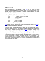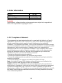
1
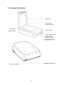
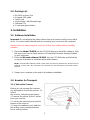
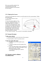
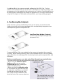
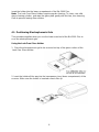
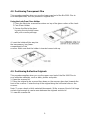
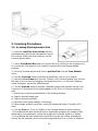
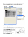
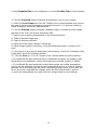
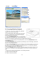
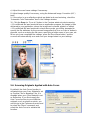
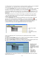
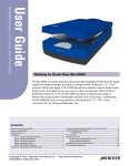
INSTRUCTION MANUAL BIO-5000 Plus VIS Gel Scanner Gel Scanner for Visible Stainings (Cat. No. BIO-5000P) SERVA Electrophoresis GmbH Carl-Benz-Str. 7 D-69115 Heidelberg Phone +49-6221-138400, Fax +49-6221-1384010 e-mail: [email protected] http://www.serva.de Contents 1. Introduction 2 2. Features of the Microtek Bio-5000 Plus 3 2.1. Specifications 3 2.2. System Requirements 3 2.3. Scanner Description 4 2.4. Packing List 5 3. Installation 5 3.1. Software Installation 5 3.2. Arrestor for Transport 3.2.1. Unlock the Scanner 3.2.2. Shipping the Scanner 5 5 6 3.3. Connect Scanner 6 3.4. Scanner control software ScanWizard Bio 6 4. Positioning the Originals 7 4.1. Positioning Electrophoresis Gels 8 4.2. Positioning Transparent Film 9 4.3. Positioning Reflective Originals 9 5. Scanning Procedures 10 5.1. Scanning Electrophoresis Gels 10 5.2. Scanning Transparent Film 11 5.3. Scanning Reflective Originals 13 5.4. Scanning Originals Applied with Auto Focus 14 6. Important for Scanning Electrophoresis Gels 16 7. File Format 17 8. Order Information 18 9. FCC Compliance Statement 18 Vers. 02/14 1 1. Introduction The Bio-5000 Plus is a combined flatbed and film scanner for electrophoresis gels and film formats as large as 21.6 x 26.0 cm that also offers additional functionality to scan reflective art or prints as large as 21.6 x 35.6 cm. The Bio-5000 Plus is equipped with Microtek's patented Emulsion Direct Imaging Technology (E.D.I.T.) for delivering distortion-free images in transparency scanning. The 0.05 minimum optical density (Dmin) provides a wider and clearer range for capturing light tones of images. The Bio-5000 Plus comes with several important features, including the following: • One machine to scan all: With specially designed Leak-Free Glass Holders. The Bio-5000 Plus allows you to scan electrophoresis gels and transparent films directly in the machine. It also supports scanning of reflective materials, such as photos and prints. • Microtek's Emulsion Direct Imaging Technology (E.D.I.T.): This is a patented “glassless” scanning system built into the lower bay of Microtek’s dual media scanners, allowing the scanner CCD to directly read the emulsion side of the film during scanning without any interfering pane of glass. This effectively eliminates problems associated with normal glass transparency scanning like Newton Rings, resulting in distortion-free images. • Auto Focus: An image improvement feature introduced to Microtek flatbeds, Auto Focus allows the scanner to change the focus position on images through the movement of the CCD, resulting in better image quality for a chosen area of the scan. Auto Focus is activated by default when the scanner is on but can be switched off manually before the final scan is carried out. The results of Auto Focus can be best seen when used with uneven, creased photos and film. • 4800 x 9600-dpi resolution: The exceptionally high resolution of the Bio-5000 Plus lets you scan even postage-size images and enlarge them with amazing clarity, with little loss of detail. The scanner's 0.05 minimum optical density (Dmin) allows it to capture a wide range of light tones approximating real-life color and hues. • Microtek ScanWizard™ Bio scanning software: This is an advanced scanner controller program that provides many powerful, professional-level features for scanning. • Hi-Speed USB interface: High-Speed USB (USB 2.0), which is capable of 480Mbps data transfer, provides plug-and-play connectivity for a hassle-free installation. 2 2. Features of the Microtek Bio-5000 Plus 2.1. Specifications Scanning Modes Color and grayscale in a single scanning pass True 48-bit color (approx. 281 x 1012 colors) 16-bit grayscale (approx. 65,536 shades of gray) Scanning Area Reflective: Max. 216 mm x 356 mm) Min. 19 mm x 19 mm) Transmission: Max. 216 mm x 260 mm) Min. 19 mm x 19 mm) Optical: 4800 dpi x 9600 dpi Interpolated: 65,535 dpi Hi-Speed USB (USB 2.0) (L x W x H) 567 mm x 385 mm x 158 mm Resolution Interface Dimensions Weight Voltage Power Consumption Environment 12 kg AC 100V to 240V; 50-60 Hz 35 W Operating Temperature: 10° C to 40° C Relative Humidity: 20% to 85% 2.2. System Requirements General Requirements • CD-ROM drive (for installing software) • Color display with 24-bit color output capability • 512 MB RAM or more PC and compatibles • Pentium IV PC or higher with USB, or Hi-Speed USB (USB 2.0) port • Microsoft Windows 2000, XP, Vista or Windows 7 3 2.3. Scanner Description 4 2.4. Packing List • • • • • Bio-5000 scanner Plus Hi-speed USB cable Power cord Vinyl stickers with Microtek logo Software CDs • 2 Leak-free glass holders 3. Installation 3.1. Software Installation Important: Do not remove the yellow sticker from your scanner until you are told to do so. You must install software before connecting your scanner to the computer! Always close any open programs, and turn off Anti-virus utilities before installing software. 1. Place the Adobe CD-ROM into the CD-ROM drive and install the software. Skip this step if you have a newer version of Photoshop Elements already installed on your computer. 2. Place the Microtek software CD-ROM into the CD-ROM drive and follow the on-screen instruction to install the driver and software. NOTE: If the Microtek software Installer screen does not come up automatically, double-click the following in succession: “My Computer”; the CD-ROM icon; the cdsetup.exe to start the installer program. 3. Restart your computer at the end of all software installation. 3.2. Arrestor for Transport 3.2.1. Unlock the Scanner Before you can operate the scanner, you will need to unlock the scanner. To unlock the scanner, follow the steps below: 1. Remove the yellow “Unlock” sticker from your scanner. 2. Look for the unlocking screw at the bottom of the scanner. 3. Using a screwdriver, push and turn the locking screw counterclockwise to the unlock position. 5 When successfully unlocked, the screw will push out a little, protruding slightly from the bottom of the scanner. 3.2.2. Shipping the Scanner If you have to transport the scanner, you will need to lock the scanner back. Follow the steps below: 1. Turn off the scanner if your scanner is on. 2. Turn the scanner back on. The scanner’s carriage will move to the Stand-by position in 5 minutes. 3. When the indicators on the front of your scanner stop blinking, use a screwdriver, and then push and turn the locking screw clockwise to the locked position. When the screw has been tightened, this indicates that your scanner is locked. 4. Turn off your scanner. The scanner is now ready for transport. 3.3. Connect Scanner To the power adapter 1. Connect the power cord to the back of the scanner 2. Plug the power cord into a power source. To the high-speed USB cable 1. Connect one end of the cable to your computer 2. Connect the other end of the cable to the scanner. 3. Press the power button at the front panel of your scanner, and wait for the lights to stop blinking and stay on steady. The system will detect your scanner automatically. 3.4. Scanner control software ScanWizard Bio 6 ScanWizard Bio is the scanner controller software for Bio-5000 Plus. The four windows of ScanWizard Bio are shown here to familiarize you with the interface and to prepare you for the material in the next session on Scanning. ScanWizard Bio can be launched as a stand-alone by clicking the program icon, or it can be launched by using the File-Import or File-Acquire command from your image-editing program. 4. Positioning the Originals Aside from the scanning of reflectives, there are two pieces of Leak-Free Glass Holders come with your scanner package, which are specifically designed to scan electrophoresis gels and transparent film. Leak-Free Glass Holders (2 pieces) (used to scan electrophoresis gels and transparent film) Proper positioning of the scan material on the scanner is important for successful scanning. Before starting scanning, refer to the individual section in the succeeding pages about how to correctly position the electrophoresis gels, transparent film, and reflectives. Before proceeding your scan, take note of the information presented below: The correct side up is the side showing the holder labels facing up. • When using the Leak-Free Glass Holders, make sure you use the correct side up when inserting the holders into the scanner. • Make sure that the calibration strip on the holders are kept clear and free of obstruction at all times; no material should ever be placed on this area. Also, make sure the calibration strip faces the front of the scanner when you 7 insert the holder into the lower compartment of the Bio-5000 Plus. Note: The Leak-Free Glass Holders require regular cleaning. To clean, use mild glass cleaning solution, and wipe the glass plate gently with lint-free, lens-cleaning cloth to prevent leaving fiber residue. 4.1. Positioning Electrophoresis Gels This procedure applies when you use the lower scan bed of the Bio-5000 Plus to scan the electrophoresis gels. Using the Leak-Free Glass Holder 1. Place the electrophoresis gel to be scanned on top of the glass surface of the Leak-Free Glass Holder. 2. Insert the holder all the way into the transparency bay (lower compartment) of the scanner. Make sure the holder is inserted correct side up. 8 4.2. Positioning Transparent Film This procedure applies when you use the lower scan bed of the Bio-5000 Plus to scan transparencies, such as positive or negative film. Using the Leak-Free Glass Holder 1.Place the film to be scanned face down on top of the glass surface of the Leak2.Free Glass Holder. 3.Secure the film to the glass by using the vinyl strips come with your scanner package. 4. Insert the holder all the way into the transparency bay (lower compartment) of the scanner. Make sure that the holder is inserted correct side up. 4.3. Positioning Reflective Originals This procedure applies when you use the upper scan bed of the Bio-5000 Plus to scan reflective materials, such as blots, photos and prints. 1. Open the scanner lid. 2. Place the original to be scanned face down on the scanner glass bed, towards the front of the scanner. Center the top of the original along the horizontal ruler on the scanner. Note: To scan a book or thick materials/documents, lift the scanner lid out of its hinge sockets high enough to create room between the originals and the lid. 3. Lower the scanner lid. 9 5. Scanning Procedures 5.1. Scanning Electrophoresis Gels 1. Insert the Leak-Free Glass Holder with the electrophoresis gel into the transparency bay of the scanner. Make sure that nothing is on the scanner glass surface. 2. Launch ScanWizard Bio either as a stand-alone by clicking on the program icon, or by using the File-Import or File-Acquire command from your image-editing program. 3. Go to the Preview window and choose positive Film from the Scan Material menu. 4. Click the Overview button to perform a preliminary scan of your original. 5. Select the Scan Frame tool from the Toolbar in the Preview window, and choose the area to be scanned by dragging a rectangle around it. You will see a flashing frame (marquee) around the selected area. 6. Click the Prescan button to display a detailed image area selected via the Scan Frame tool. A thumbnail of the image appears in the Scan Job Queue window as well. 7. Specify your scanning requirements in the Settings window. a) Select a desired image type. b) Select a desired resolution. c) Adjust the scan frame settings if necessary. 8. Adjust image quality if necessary, using the Advanced Image Correction (AIC) tools. 9. Click the Scan (or “Scan to”) button in the Preview window to start scanning. • If ScanWizard Bio was launched from an application program, the image is then delivered to your application, where the image can be saved, printed, or edited. • If ScanWizard Bio was launched in stand-alone mode, you will be prompted to specify the file attributes for the scanned image after the Scan or Scan to button is 10 pressed, such as entering the file name, specifying a folder name of your own, etc. When you have completed the settings, press the Done/Save button, and the scanner will automatically scan and save your image based on your settings. 5.2. Scanning Transparent Film 1. Insert the Leak-Free Glass Holder with the film into the transparency bay of the scanner. Make sure that nothing is on the scanner glass surface. 2. Launch ScanWizard Bio either as a standalone by clicking on the program icon, or by using the File-Import or File-Acquire command from your image-editing program. 3. Go to the Preview window of ScanWizard Bio, and choose the correct type for the film from the Scan Material menu. 11 Choose Negative Film to scan negatives, or choose Positive Film to scan positives. 4. Click the Overview button to perform a preliminary scan of your original. 5. Select the Scan Frame tool from the Toolbar in the Preview window, and choose the area to be scanned by dragging a rectangle around it. You will see a flashing frame (marquee) around the selected area. 6. Click the Prescan button to display a detailed image. A thumbnail of the image appears in the Scan Job Queue window as well. 7. Specify your scanning requirements in the Settings window. a) Select a desired image type. b) Select a desired resolution. c) Adjust the scan frame settings if necessary. 8. Adjust image quality if necessary, using the Advanced Image Correction (AIC) tools. 9. If the colors in your film are faded and need restoring, check the “Automatic Color Restoration” box in the Settings window. 10. Click the Scan (or “Scan to”) button in the Preview window to start scanning. • If ScanWizard Bio was launched from an application program, the image is then delivered to your application, where the image can be saved, printed, or edited. • If ScanWizard Bio was launched in stand-alone mode, you will be prompted to specify the file attributes for the scanned image after the Scan or Scan to button is pressed, such as entering the file name, specifying a folder name of your own, etc. When you have completed the settings, press the Done/Save button, and the scanner will automatically scan and save your image based on your settings. 12 5.3. Scanning Reflective Originals 1. Raise the scanner lid, and place the reflective original to be scanned face down on the scanner glass bed, towards the front of the scanner. Center the top of the original along the horizontal ruler on the scanner. 2. Launch ScanWizard Bio either as a stand-alone by clicking on the program icon, or by using the FileImport or File-Acquire command from your image-editing program. 3. Go to the Preview window of ScanWizard Bio, and choose Reflective from the Scan Material menu. 4. Click the Overview button to perform a preliminary scan of the image, which will appear in the Preview window. 5. Select the Scan Frame tool from the Toolbar in the Preview window, and choose the area to be scanned by dragging a rectangle around it. You will see a flashing frame (marquee) around the selected area. 6. Click the Prescan button to display a detailed image area selected via the Scan Frame tool. A thumbnail of the image appears in the Scan Job Queue window as well. 7. Specify your scanning requirements in the Settings window. a) Select a desired image type. b) Select a desired resolution. 13 c) Adjust the scan frame settings if necessary. 8. Adjust image quality if necessary, using the Advanced Image Correction (AIC) tools. 9. If the colors in your reflective original are faded and need restoring, check the “Automatic Color Restoration” box in the Settings window. 10. Click the Scan (or “Scan to”) button in the Preview window to start scanning. • If ScanWizard Bio was launched from an application program, the image is then delivered to your application, where the image can be saved, printed, or edited. • If ScanWizard Bio was launched in stand-alone mode, you will be prompted to specify the file attributes for the scanned image after the Scan or Scan to button is pressed, such as entering the file name, specifying a folder name of your own, etc. When you have completed the settings, press the Done/Save button, and the scanner will automatically scan and save your image based on your settings. 5.4. Scanning Originals Applied with Auto Focus By default, the Auto Focus function is activated when your Scan Material is set as Positive Film or Negative Film. It is disabled when your Scan Material is set as Reflective. If you like to apply the Auto Focus function to your reflective originals, such as photos or prints, you need to go to the Preferences menu and to select the “More” command, and select the Auto Focus to activate this function. 14 1. Follow steps 1 to 3 in the previous scanning scenarios to place your scan material (electrophoresis gel, reflective or film), and to launch ScanWizard Bio. 2. Click the Overview button to perform a preliminary scan of the image. If this is the first time to scan your scan material, you can see a flashing frame (enclosed by dotted lines) together with a default Auto Focus target sign ( ) appearing on the preview area. The Auto Focus target sign marks the area where the Auto Focus is applied to. 3. To apply the Auto Focus function to the image, use either of the ways below: • The area applied with the Auto Focus function is decided and selected by the software system automatically. Click the Overview button to perform a preliminary scan of the image, which will appear in the Preview window. Immediately, you can see a target sign ( ) appearing on the overview image. The target sign marks the area where the Auto Focus is applied to. In this case, the software system automatically detects, calculates and selects the area applied with the Auto Focus function. Select and apply the Auto Focus function to a specific area of the scan frame by yourself a) Select the Scan Frame tool from the Toolbar in the Preview window, and choose the area to be scanned by dragging a rectangle around it. b) Select the Auto Focus tool from the Toolbar in the Preview window, and choose the area in the scan frame to which the AF function will be applied. A redefined Auto Focus frame (bordered in red) will appear within the scan frame, labeled with the tag “AF”. 15 Note: The AF frame works only in the area defined by the scan frame. 4. In the Preview window, click the Prescan button. This will give you a more detailed view of the image area in which the AF function is applied. 5. If necessary, follow steps 7 to 9 (or 10) in the previous scanning scenarios to define scan settings for your image. 6. Click the Scan (or “Scan to”) button in the Preview window to start the final scan. This final scan process will include the Auto Focus function to make the image look clearer and sharper. 6. Important for Scanning Electrophoresis Gels These hints are copied from the 2D Gel Scanning Guide by Dr. Jörg Bernhardt, with friendly permission by DECODON GmbH, Greifswald, Germany. For more detailed information see: http://www.decodon.com/Support/Howto/Scanning/scanning_2D_gels.html 1. 2. Use grayscale instead of color images. Try to use the complete available grayscale range. Check this using the image histogram. 3. Choose the image resolution such that the most narrow or smallest spots you want to analyze have a diameter of at least 5 pixels. Use the image resolution table as a guide. 4. Scan all gel images using the same orientation. 5. Place each gel at the same position on the scanner plate. Avoid scanning of large blank areas around the gel. 6. Use presets in the scanner's software to make the scanning process easy and reproducible. Save resolution and scanning area as presets and reuse them for all gels in your experiment. 7. Avoid Photoshop and similar general image processing software if you do not know exactly what you are doing. Use the software that came with your scanner / imager for image post-processing. 8. Limit post-processing of images to crop, mirror, and rotation by 90, 180, 270 degrees. 9. Ideally create TIFF files. TIFF images can have different color depths. This is one of the reasons why TIFF iswidely used as standard image file format (see below: File Format). 10. Avoid using JPEG files for quantitative analysis. 16 7. File Format When your image file is, for example, a "16-bit TIFF" file this means that image intensities are encoded with 16 bit numbers, giving 65,536 (2 to the power of 16) possible different values for each pixel. In contrast, an 8-bit image file only stores 256 different values per pixel. The number of bits per pixel is also called the color depth. The following table shows some examples. color depth intensity levels 1 bit example 2 black and white FAX image 8 bit 256 GIF image 10 bit 1,024 TIFF image 12 bit 4,096 TIFF image 16 bit 65,536 TIFF image Typical color depths TIFF images can have different color depth, this is one of the reasons why TIFF is widely used as standard image file format. Generally, having more possible intensity values per pixel (higher color depth) is needed for advanced analysis. The tradeoff is between higher accuracy and need for more space to store the information: a 16 bit TIFF file is twice as large as the equivalent 8-bit file, but results in 256 times more nuances in the image that can be processed. Nonetheless, it has to be considerate that often image processing programs are not able to deal with color depths greater than 8 bit. Decreasing color depth in the scanned image file normally results in loss of accuracy. It is not recommended to increase color depth after the scan is completed: if your scanner produced only an 8-bit image you have at most 256 different intensity values in the image. Converting the file to a 16-bit image will only give you at most 256 out of 65,536 possible gray values. 17 8. Order Information Product GelScan 6.0 GelScan 6.0 Pro GelScan 6.0 HTS Cat. No. GS-V60 GS-V60P GS-V60HTS Important Specifications, software bundles, and accessories are subject to change without notice. Not responsible for typographic errors. 9. FCC Compliance Statement This equipment has been tested and found to comply with the limits for a Class B digital device, pursuant to Part 15 of the FCC rules. These limits are designed to provide reasonable protection against harmful interference in a residential installation. This equipment generates, uses and can radiate radio frequency energy and, if not installed and used in accordance with the instructions, may cause harmful interference to radio communications. However, there is no guarantee that interference will not occur in a particular installation. If this equipment does cause harmful interference to radio or television reception, which can be determined by turning the equipment off and on, the user is encouraged to try to correct the interference by one or more of the following measures: • Reorient or relocate the receiving antenna. • Increase the separation between the equipment and receiver. • Connect the equipment into an outlet on a circuit different from that to which the receiver is connected. • Consult the dealer or an experienced radio/TV technician for help. Note: A shielded Hi-Speed USB interface cable with ferrite core installed on the scanner connector and must be used with this equipment. Caution: Changes or modifications not expressly approved by the manufacturer responsible for compliance could void the user's authority to operate the equipment. This device complies with Part 15 of the FCC Rules. Operation is subject to the following two conditions: (1) This device may not cause harmful interference, and (2) this device must accept any interference received, including interference that may cause undesired operation. 18