1
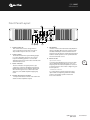
User
Manual
MODEL: QM 1000P
Contents
Safety Precautions. . . . . . . . . . . . . . . . . . . . . . . . . . . . . . . . . . . . . . . . . . . . . . . 1
General Description. . . . . . . . . . . . . . . . . . . . . . . . . . . . . . . . . . . . . . . . . . . . . . 4
Front Panel Layout. . . . . . . . . . . . . . . . . . . . . . . . . . . . . . . . . . . . . . . . . . . . . . . 5
Rear Panel Layout . . . . . . . . . . . . . . . . . . . . . . . . . . . . . . . . . . . . . . . . . . . . . . . 6
Connections Block Diagram. . . . . . . . . . . . . . . . . . . . . . . . . . . . . . . . . . . . . . 7
Diagram: . . . . . . . . . . . . . . . . . . . . . . . . . . . . . . . . . . . . . . . . . . . . . . . . . . . . . . . . 7
Specifications. . . . . . . . . . . . . . . . . . . . . . . . . . . . . . . . . . . . . . . . . . . . . . . . . . . . 8
Dimensional Diagram. . . . . . . . . . . . . . . . . . . . . . . . . . . . . . . . . . . . . . . . . . . . 9
Glossary. . . . . . . . . . . . . . . . . . . . . . . . . . . . . . . . . . . . . . . . . . . . . . . . . . . . . . . . . 10
Operating Tips. . . . . . . . . . . . . . . . . . . . . . . . . . . . . . . . . . . . . . . . . . . . . . . . . . . 11
QM 1000P
User Manual
Safety Precautions
• Be sure to read the instructions in this section carefully before use.
• Make sure you observe the instructions in this manual as the conventions of safety symbols and
messages are very important.
• We also recommend you keep this instruction manual handy for future reference.
Safety Symbol and Message Conventions
Safety symbols described below are used in this manual to prevent bodily injury and property
damage which could result from mishandling. Before operating your product, read this manual first
and understand the safety symbols and messages so you are thoroughly aware of any risks.
1
WARNING
Indicates a potentially hazardous situation which, if
mishandled, could result in death or serious personal injury.
CAUTION
Indicates a potentially hazardous situation which, if
mishandled, could result in moderate or minor personal injury,
and/or property damage.
Q Motion Series
QM 1000P
User Manual
QM 1000P
User Manual
WARNING
When Installing the Unit
• Do not expose the unit to rain or an
environment where it may be splashed by
water or other liquids, as doing so may
result in fire or electric shock.
• Use the unit only with the voltage
specified on the unit. Using a voltage
higher than that which is specified may
result in fire or electric shock.
• Do not cut, kink, otherwise damage nor modify
the power supply cord. In addition, avoid using
the power cord in close proximity to heaters,
and never place heavy objects -- including the
unit itself -- on the power cord, as doing so may
result in fire or electric shock.
2
• Be sure to replace the unit’s terminal cover
after connection completion. Because
high voltage is applied to the speaker
terminals, never touch these terminals to
avoid electric shock.
• Install in a well ventilated equipment rack
away from heat sources.
When the Unit is in Use
• Should the following irregularity be found
during use, immediately switch off the
power, disconnect the power supply plug
from the AC outlet and contact your nearest
Quest dealer. Make no further attempt to
operate the unit in this condition as this
may cause fire or electric shock.
• If you detect smoke or a strange smell
coming from the unit.
• If water or any metallic object gets into
the unit
• If protect lights are illuminated or the clip
lights stay on for more than one second
• If the power supply cord is damaged
(exposure of the core, disconnection, etc.)
• To prevent a fire or electric shock, never
open the unit case as there are high voltage
components inside the unit. Refer all
servicing to your nearest Quest dealer.
• Do not place cups, bowls, or other
containers of liquid or metallic objects on
top of the unit. If they accidentally spill into
the unit, this may cause a fire or electric
shock.
• Do not insert nor drop metallic objects or
flammable materials in the ventilation slots
of the unit’s cover, as this may result in fire
or electric shock.
User Manual
Q Motion Series
QM 1000P
QM 1000P
User Manual
CAUTION
When Installing the Unit
• Never plug in nor remove the power supply
plug with wet hands, as doing so may cause
electric shock.
• When unplugging the power supply cord, be
sure to grasp the power supply plug; never
pull on the cord itself. Operating the unit
with a damaged power supply cord may
cause a fire or electric shock.
• When moving the unit, be sure to remove
its power supply cord from the wall outlet.
Moving the unit with the power cord
connected to the outlet may cause damage
to the power cord, resulting in fire or electric
shock. When removing the power cord, be
sure to hold its plug to pull.
When the Unit is in Use
• Do not place heavy objects on the unit
as this may cause it to fall or break which
may result in personal injury and/or
property damage. In addition, the object
itself may fall off and cause injury and/or
damage.
• Make sure that the volume control is set
to minimum position before the power is
switched on. The possibility of a loud noise
produced at high volume when power is
switched on can impair hearing.
• Do not operate the unit for an extended period
of time then the sound is distorting. This is an
indication of a malfunction, which in turn will
generate heat and result in a fire.
• Do not block the ventilation slots front intake
or rear hot air outlet. Doing so may cause
heat to build up inside the unit and result in
fire.
• Contact your dealer in regards to how to best
clean the unit. If dust is allowed to accumulate
in the unit over a long period of time, a fire or
damage to the unit may result.
• Avoid installing the unit in humid or dusty
locations, in locations exposed to direct
sunlight, near heaters, or in locations
generating sooty smoke or steam as doing
otherwise may result in fire or electric shock.
• If dust accumulates on the power supply plug
or in the wall AC outlet, a fire may result. Please
clean the connection periodically. In addition,
insert the plug into the wall outlet securely.
3
• Switch off the power, and unplug the power
supply plug from the AC outlet for safety
purposes when cleaning or leaving the unit
unused for 10 days or more.
Doing otherwise may result in fire or electric
shock.
An all-pole mains switch with a contact separation of at least 3mm in each pole shall be
incorporated in the electrical installation of the building.
Q Motion Series
QM 1000P
User Manual
QM 1000P
User Manual
General Description
The compact QM 1000P amplifier is a 2-way
stereo combination sub bass and satellite
composite amplifier powered with three
internal amplifiers. It can power up to four
satellite speakers and two sub bass boxes.
It is designed as a complete multi-way
amplifier package for mobile live sound and
permanent installation venues. The QM 1000P
is a compact alternative to the size, bulk and
expense of a conventional multiple amplifier
rack and system controller where a full range
system of medium power is required.
Connect almost any combination or
type of speaker
4
Almost any combination of satellite or sub bass
speakers can be connected and function with
the QM 1000P amplifier. User adjustable high
and low pass filter networks and a master limiter
allow for a variety of speaker box options and for
a variety of live and installed sound applications.
The adjustable master output limiter can be set
to protect lower powered speakers if the owner
wishes to use an alternative speaker combination.
Each internal amplifier is also equipped with soft
knee clipping protection as an extra precaution.
Your choice of QM series speakers
The ideal combination for the QM 1000P is a pair of
QM600S 15” sub bass boxes and two or four QM108
/QM10DC speakers. The QS150/230/300i speakers
will also function well with the QM 1000P and the
satellite amplifiers can be switched to full range
operation for 12” and 15” speakers.
User Manual
Q Motion Series
QM 1000P
QM 1000P
User Manual
Front Panel Layout
5
1
2
3
1.   Sub bass high cut
This control can be used to change the bass
crossover frequency from 80 Hz to 200 Hz. For
deep sub bass response select 80 – 100Hz.
2.   Limiter control
The threshold level where system limiting begins
to occur is adjustable and can be set to protect
low power handling speakers or as a max SPL
adjustment when noise level needs to be limited for
environmental reasons.
3.   Status indicators
There are indicatiors for signal presence, clip/
compression and power. The QM 1000P soft knee
limiting will prevent severe amplifier clipping, but
when a mixer signal source is driven into severe
distortion, some audible amplifier clipping may
result.
4.   Satellite volume level controls
L + R input and sub bass volume controls drive the
satellite and bass amplifiers outputs.
6
4
5.   Sub Volume
Volume control for the internal 950 watt (4Ω) mono
sub bass amplifier. When used in conjunction with
the Master L&R input, a balance between the low
frequencies of the sub bass and the mid high output
from the satellite speakers can be optimised for the
venue and the music source.
6.   Power on/off
Operational Note:
For tuning and adjusting the bass sound, set high
cut for adjustment of the upper bass cross-over
frequency fowr the Sub bass amplifier set to below
100 Hz for low bass, above 125 for a higher range of
bass frequencies.
5
Subwoofer volume:
To control sub bass volume level. By increasing
input volume and adjusting subwoofer volume,
a balance the satellite speakers and the sub
bass can be achieved.
Q Motion Series
QM 1000P
User Manual
QM 1000P
User Manual
Rear Panel Layout
2
3
CAUTION
RISK OF ELECTRIC SHOCK
DO NOT OPEN
1
1.   Satellite high pass crossover
The satellite speakers can be powered with full
range signal or a cross-over to sub frequency of
80Hz or 120Hz can be selected. For 8” speakers,
120Hz is suggested. When using 10”-12” speakers,
80Hz is be preferable and high powered 12” or 15”
speakers can be set to full range.
6
User Manual
2.   Inputs
Connect signal leads from your mixer (master
left/right, line out, to the balanced inputs using
XLR mic leads. XLR connectors to be wired as
follows: 1 ground, 2 +, 3 -.
Q Motion Series
QM 1000P
3
3.   Outputs
Speakon output connectors on rear wired L&R
pin 1+ pin1-. Neutric NL4 or NL2 connectors
are recommended. The total impedance per
output should not be below 4Ω (Ohms)
(3.7Ω DC resistance). 2 x 8Ω satellite
speakers and 1 x 8Ω bass speakers can be
connected per amplifier output.
QM 1000P
User Manual
Connections Block Diagram
One amplifier connected to 2 x 8Ω subs and 2 full range boxes per L&R channel
10
10
5
5
1
1
1
2
CAUTION
RISK OF ELECTRIC SHOCK
DO NOT OPEN
1
7
1.   Male XLR line level link through
WARNING
Speakon Input and Output
Connector Wiring
• Connect a maximum of two 8Ω sub
bass boxes. Maximum load to the bass
amplifier must not be lower than 4Ω.
• Two 8Ω speaker boxes will have a
combined impedances of 4Ω. If the sub
bass box is a 4Ω sub bass, only one sub
box can be connected.
Q Motion Series
QM 1000P
User Manual
QM 1000P
User Manual
Specifications
Test condition
Satellite amplifier
SUB Woofer
amplifier
8Ω
2 x 210W
1 x 610W
4Ω
2 x 350W
1 x 940W
Frequency response
+0/-0.3dB, @1W/8Ω
20----20KHz
20---300
Distortion
Rated power -10db
<=0.05%
<=0.05%
Intermodulation Distortion
60Hz&7KHz/4:1
<=0.05%
<=0.05%
Damping factor
200Hz at 8Ω
>=300
>=300
Sensitivity
Rated power 8Ω
0.775V
0.775V
Input Impedance
Balance/unbalance
20K/10K
S/N ratio
A Weight
>106dB
Cross talk
A Weight
>60dB
Power Output *
8
Slew rate
>25V/uS
>25V/uS
Sensitivity
0.775V
0.775V
Satellite LOWCUT
Off,80,125Hz
SUB HICUT
Protection
80----200HZ
Short circuit
protection
Dimensions
Weight
* Power output specifications will vary
depending on power supply. Recommended
power range 220V - 240V. Power rating tests
performed at 240V. Tests at lower voltage (220v)
will have a small reduction on output power
User Manual
Q Motion Series
QM 1000P
DC protection
Over current
protection
QM 1000P
User Manual
Dimensional Diagram
490mm
436mm
24mm
9
410mm
440mm
490mm
Q Motion Series
QM 1000P
User Manual
QM 1000P
User Manual
Basic professional audio practice and hints for best
results.
PRE-AMPLIFIER: A part of the signal chain where
a signal from a microphone, turntable, CD player
or other source is first amplified. This will normally
be at the input of a mixer. The pre-amplifier is
necessary to boost the signal enough to be then
mixed and amplified by a power amplifier.
POWER AMPLIFIER: Boosts the signal enough so it
can be reproduced by a loudspeaker.
COMPRESSION: A process that reduces the dynamic
range of signal. In other words, the loud parts of a
signal are decreased while the quiet parts appear
louder. When used correctly, compression can
make live music sound more even and balanced.
LIMITER: An electronic device that will prevent
the signal from exceeding a set level of output.
Normally used as a system protection to prevent
signal from being over driven by excessive input.
10
Compressor
Threshold
Output Level
Glossary
3:1
1:1
10
SELF-POWERED: Refers to a speaker or a
mixer that contains a power amplifier.
10
PHASE (IN or OUT OF PHASE): This really means
speaker polarity. The input terminals of a normal
loudspeaker have a + positive red terminal and
a - negative black terminal. In the case where there
are two speakers operating as a pair or together
10
Limiter
Threshold
Output Level
ELECTRONIC CROSS OVER: Splits the full range
audio signal to separate high and low frequencies.
This is done to send low frequencies to the bass
speaker and high frequencies to the tweeter or
high frequency horn driver.
0:1
1:1
10
CLIPPING: Distortion that is caused by having too
much signal at an input causing the amplifier to
overload. It is called clipping because it will cause a
smooth wave to be cut off at the peak of the wave.
In other words, “clipped”.
GAIN STRUCTURE: The relationship of input levels
to output levels in a signal chain. An example of
incorrect gain structure is when a mixer is turned
Clipping
Clipping
up to the point of audible distortion (red lights
flashing and signal overload), while the power
amplifiers are turned down and running at only
30% power.
User Manual
Q Motion Series
QM 1000P
as an array, the wiring must be the same from one
speaker to the next. If a speaker connector, speaker
lead or speaker box is wired in reverse to a box near
it, loss of performance will result. This may be in the
form of lost low frequency response. In this case
you will see the bass speaker working hard but as
you move away from the box, the bass frequencies
will seem to “disappear”.
Check that your speaker leads do not
have one lead wired in reverse at one end
and that the speaker boxes are all wired
correctly internally. This can happen when
a speaker box has been repaired and then
not assembled with the wiring connected
correctly.
QM 1000P
User Manual
Operating Tips
To avoid overloading the pre-amp inputs, always
operate the master volume at a high level and
control the volume from the input volume. The
ideal situation is to have all the components of
the audio chain operating at the same operational
range.
MIXER
10
10
5
5
1
1
1
10
CLIP/LIMIT
2
MIXER
Do not operate the system with the input peaking
(red overload light on or flashing) and the master
volume turned down.
If you run the row of red lights to the end of the
ramp you will cause distortion at the very start of
the pre amplifier stage of the mixer. At this point
it will sound dirty and “fizzy” regardless of how
good the rest of your sound system is. The rest of
the system will be reproducing a distorted sound.
If you need more volume, turn down the input
signal so it is out of the red and turn up the output
of the mixer.
5
0
Do not run the system with the mixer “peaking in
the red” while the box is turned down.
Red lights flashing on a mixer indicate distortion. If
you have a mixer with the facility to show you the
input level on a meter, for example then you push
a CUE/PFL button, set the input level to below the
level of the red end of the LED ramp.
AMP
AMP
10
10
5
5
1
1
5
0
1
10
CLIP/LIMIT
2
MIXER
AMP
10
10
5
5
1
1
0
1
11
5
10
CLIP/LIMIT
2
Q Motion Series
QM 1000P
User Manual
Register Your Product
Thank you for choosing Quest. Please take the time
to complete your product registration card which is
included with the packaging.
Registering your Quest Engineering product will:
• CONFIRM YOUR WARRANTY
• REGISTER YOUR PRODUCT
• PROTECT YOUR NEW PRODUCT
REGISTER ONLINE:
www.questaudio.net/registration
www.questaudio.net