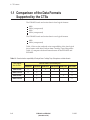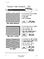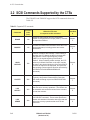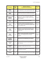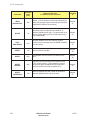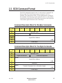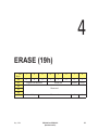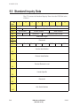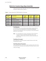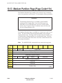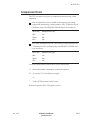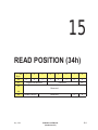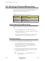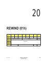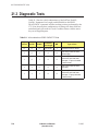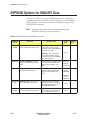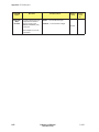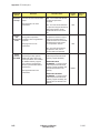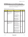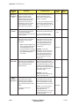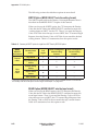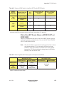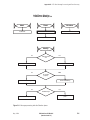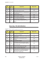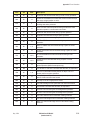
1
(;%0;538#)#(;%0;838#;PP# 7DSH#'ULYHV IRU#VWDQGDUG#DQG#H;WHQGHG0/HQJWK#FRQILJXUDWLRQV 6&6,# 5HIHUHQFH 510503-004 Copyright Copyright 1994 by Exabyte Corporation. All rights reserved. This item and the information contained herein are the property of Exabyte Corporation. No part of this document may be reproduced, transmitted, transcribed, stored in a retrieval system, or translated into any language or computer language in any form or by any means, electronic, mechanical, magnetic, optical, chemical, manual, or otherwise, without the express written permission of Exabyte Corporation, 1685 38th Street, Boulder, Colorado 80301. Disclaimer Exabyte Corporation makes no representation or warranties with respect to the contents of this document and specifically disclaims any implied warranties of merchantability or fitness for any particular purpose. Further, Exabyte Corporation reserves the right to revise this publication without obligation to notify any person or organization of such revision or changes. Trademark Notices EXABYTE is a registered trademark and EXATAPE and Compression Integrity Check are trademarks of Exabyte Corporation. All other product names are trademarks or registered trademarks of their respective companies. Revision History Revision 000 (preliminary) Date November 1991 001 (preliminary) 002 003 (preliminary for XL products) 004 October 1992 November 1992 April 1994 May 1994 See page iv for information about the changes and enhancements to this revision. Exabyte Corporation 1685 38th Street Boulder, Colorado 80301 (303) 442-4333 510503-004 ii EXB-8205 and EXB-8505 (Standard and XL) 510503 Product Warranty Caution The EXB-8505, EXB-8505XL, EXB-8205, and EXB-8205XL 8mm Cartridge Tape Subsystems (CTSs) are warranted to be free from defects in materials, parts, and workmanship and will conform to the current product specification upon delivery. For the specific details of your warranty, refer to your sales contract or contact the company from which the CTS was purchased. The warranty for the CTS shall not apply to failures caused by: Physical abuse or use not consistent with the operating instructions or product specification provided by Exabyte’s personnel or agent for the applicable equipment. Use of any type of cleaning material other than an EXABYTE 8mm Cleaning Cartridge (or an Exabyte-approved cleaning cartridge). Modifications by other than Exabyte’s personnel or agent in any way other than those approved by Exabyte, provided the warranty shall not be voided by the repair or replacement of parts or the attachment of items in the manner described in maintenance or installation instructions provided by Exabyte. Repair by other than Exabyte’s personnel or agent in a manner contrary to the maintenance instructions provided by Exabyte. Removal of the Exabyte serial number tag. Physical abuse due to improper packaging of returns. CAUTION Returning the CTS in unauthorized packaging may damage the unit and void the warranty. If you are returning the CTS for repair, package it in its original packaging (or in replacement packaging obtained from your vendor). Refer to the packing instructions in EXB-8205 and EXB-8505 Installation and Operation. If problems with the CTS occur, contact your maintenance organization; do not void the product warranty by allowing untrained or unauthorized personnel to attempt repairs. May 1994 EXB-8205 and EXB-8505 (Standard and XL) iii Changes and Enhancements to This Manual This revision (510503-004) of the EXB-8205 and EXB-8505 SCSI Reference for Standard and eXtended-Length (XL) Configurations replaces the EXB-8205 User’s Manual (510501-001) and the EXB-8505 User’s Manual (510503-002). This manual includes the following changes and enhancements: The title of this manual has been changed from “User’s Manual” to “SCSI Reference” to more accurately reflect its content. Information for the EXB-8505 and EXB-8205 has been consolidated into one manual. Information for the “eXtended-Length” (XL) configurations of these CTSs has also been included Where differences exist between the products, these differences are noted. The chapters describing the MODE SELECT and MODE SENSE commands have been combined into one chapter for easier reference. Installation and operation information has been removed from this manual and is now available in a separate publication: EXB-8205 and EXB-8505 Installation and Operation (302967). Instructions for creating and using a microcode update tape have been removed. Up-to-date instructions are now available in the online documentation for the CTS Monitor program. iv EXB-8205 and EXB-8505 (Standard and XL) 510503 Contents About This Manual xix 1 CTS Features 1-1 1.1 Comparison of the Data Formats Supported by the CTSs 1.2 Structure of Data on Tape . . . . . . . . . . . . . . . . . . . Physical Track Structure . . . . . . . . . . . . . . . . . . Data Elements on Tape . . . . . . . . . . . . . . . . . . . 1.3 Controls and Indicators . . . . . . . . . . . . . . . . . . . . Unload Button . . . . . . . . . . . . . . . . . . . . . . . . LEDs . . . . . . . . . . . . . . . . . . . . . . . . . . . . . 1.4 Customizing CTS Operation with EEPROM Options . . . . . . . . . . . . . . . . . . . . . . . . . . . . . . . . . . . . . . . . . . . . . . . . . . . . . . . . . . . . . . . . . . . . . . . . . . . . . . . . . . . . . . . . . . . . . . . . . . . . . . . . . . . 2 SCSI Communication 2-1 2.1 Overview of SCSI Communication . . . . . . . . . . . . 2.2 SCSI Commands Supported by the CTSs . . . . . . . . . 2.3 SCSI Command Format . . . . . . . . . . . . . . . . . . . Command Descriptor Block for Six-Byte Commands Command Descriptor Block for Ten-Byte Commands Format of the Operation Code . . . . . . . . . . . . . Typical Format of the Control Byte . . . . . . . . . . . 2.4 Field Definitions for the Command Descriptor Block . . Field Definitions for Six-Byte CDBs . . . . . . . . . . Field Definitions for Ten-Byte CDBs . . . . . . . . . . 2.5 Command Format Errors . . . . . . . . . . . . . . . . . . 2.6 Command Status . . . . . . . . . . . . . . . . . . . . . . . 2.7 Message System . . . . . . . . . . . . . . . . . . . . . . . Command Complete (00h) . . . . . . . . . . . . . . . Extended Message (01h) . . . . . . . . . . . . . . . . . Save Data Pointer (02h) . . . . . . . . . . . . . . . . . Restore Pointers (03h) . . . . . . . . . . . . . . . . . . Disconnect (04h) . . . . . . . . . . . . . . . . . . . . . Initiator Detected Error (05h) . . . . . . . . . . . . . . Abort (06h) . . . . . . . . . . . . . . . . . . . . . . . . Message Reject (07h) . . . . . . . . . . . . . . . . . . . No Operation (08h) . . . . . . . . . . . . . . . . . . . . Message Parity Error (09h) . . . . . . . . . . . . . . . Bus Device Reset (0Ch) . . . . . . . . . . . . . . . . . . Identify (80h or C0h) . . . . . . . . . . . . . . . . . . . Message Sequence . . . . . . . . . . . . . . . . . . . . May 1994 1-4 1-6 1-6 1-9 1-13 1-14 1-15 1-17 EXB-8205 and EXB-8505 (Standard and XL) . . . . . . . . . . . . . . . . . . . . . . . . . . . . . . . . . . . . . . . . . . . . . . . . . . . . . . . . . . . . . . . . . . . . . . . . . . . . . . . . . . . . . . . . . . . . . . . . . . . . . . . . . . . . . . . . . . . . . . . . . . . . . . . . . . . . . . . . . . . . . . . . . . . . . . . . . . . . . . . . . . . . . . . . . . . . . . . . . . . . . . . . . . . . . . . . . . . . . . . . . . . . . . . . . . . . . . . . . . . . . . . . . . . . . . . . . . . . . . . . . . . . . . . . . . . . . . . . . . . . . . . . . . . . . . . . . . . . . . . . . . . . . . . . . . . . . . . . . . . . . . . . . . . . . . . . . . . . . . . . . . . . . . . . . . . . . . . . . . . . . . . . . . . . . . . . . . . . . . . . . . . . 2-2 2-4 2-7 2-7 2-7 2-8 2-8 2-9 2-9 2-10 2-11 2-12 2-15 2-16 2-16 2-18 2-18 2-18 2-19 2-19 2-19 2-20 2-20 2-20 2-21 2-22 v 3 Implementing CTS Operations 3-1 3.1 Using Data Cartridges . . . . . . . . . . . . . . . . . . . . . Loading Data Cartridges . . . . . . . . . . . . . . . . . . Unloading Data Cartridges . . . . . . . . . . . . . . . . 3.2 Controlling the Format of Data on the Tape . . . . . . . . 3.3 Using Data Compression . . . . . . . . . . . . . . . . . . . Using the EXB-8505 to Write Compressed Data . . . . . Using the EXB-8205 to Write Compressed Data . . . . . 3.4 Setting the Size of Data Blocks . . . . . . . . . . . . . . . . Optimizing Block Size: 8200 Format . . . . . . . . . . . Logical Block Packing: All Other Data Formats . . . . 3.5 Using Filemarks and Setmarks . . . . . . . . . . . . . . . . Filemarks . . . . . . . . . . . . . . . . . . . . . . . . . . . Setmarks (EXB-8505 Writing in 8500c Format Only) . . 3.6 Using Streaming vs. Start/Stop Mode . . . . . . . . . . . . Streaming Mode . . . . . . . . . . . . . . . . . . . . . . . Start/Stop Mode . . . . . . . . . . . . . . . . . . . . . . Matching Host and CTS Data Transfer Rates . . . . . . Using the Motion Threshold and Reconnect Threshold 3.7 Formatting and Using Partitions (EXB-8505) . . . . . . . . What Are Partitions? . . . . . . . . . . . . . . . . . . . . How Do You Create Partitions? . . . . . . . . . . . . . . How Do You Use a Dual-Partition Tape? . . . . . . . . 3.8 Using Directory Support . . . . . . . . . . . . . . . . . . . . 3.9 Handling Unit Attention Conditions . . . . . . . . . . . . . Effect of Changing Data Cartridges . . . . . . . . . . . . Clearing the Unit Attention Condition . . . . . . . . . . 3.10 Resetting the CTS . . . . . . . . . . . . . . . . . . . . . . . Effect of Power-on Reset . . . . . . . . . . . . . . . . . . Effect of SCSI Bus and Device Resets . . . . . . . . . . . Reset Processing . . . . . . . . . . . . . . . . . . . . . . . . . . . . . . . . . . . . . . . . . . . . . . . . . . . . . . . . . . . . . . . . . . . . . . . . . . . . . . . . . . . . . . . . . . . . . . . . . . . . . . . . . . . . . . . . . . . . . . . . . . . . . . . . . . . . . . . . . . . . . . . . . . . . . . . . . . . . . . . . . . . . . . . . . . . . . . . . . . . . . . . . . . . . . . . . . . . . . . . . . . . . . . . . . . . . . . . . . . . . . . . . . . . . . . . . . . . . . . . . . . . . . . . . . . . . . . . . . . . . . . . . . . . . . . . . . . . . . . . . . . . . . . . . . . . . . . . . . . . . . . . . . . . . . . . . . . . . . . . . . . . . . . . . . . . . . . . . . . . . . . . . . . . . . . . . . . . . . . . . . . . . . . . . . . . . . . . . . . . . . . . . . . . . 4 ERASE (19h) 4.1 4.2 4.3 4.4 4-1 About This Command . . . . . . Field Definitions . . . . . . . . . Tape Positioning . . . . . . . . . Exceptions and Error Conditions . . . . . . . . . . . . . . . . . . . . . . . . . . . . . . . . . . . . . . . . . . . . . . . . . . . . . . . . . . . . . . . . . . . . . . . . . . . . . . . . . . . . . . . . . . . . . . . . . . . . . . . . . . . . . . . . 5 INQUIRY (12h) 5.1 5.2 5.3 5.4 5.5 vi 3-2 3-3 3-3 3-8 3-9 3-10 3-11 3-12 3-12 3-13 3-15 3-15 3-16 3-17 3-17 3-17 3-18 3-19 3-23 3-23 3-25 3-27 3-31 3-32 3-32 3-33 3-34 3-34 3-35 3-36 4-2 4-3 4-4 4-4 5-1 About This Command . . . . . . . . Field Definitions . . . . . . . . . . . Standard Inquiry Data . . . . . . . . Supported Vital Product Data Page Unit Serial Number Page . . . . . . . . . . . . . . . . . . . . . . . . . . . . . . . . . . . . . . . . . EXB-8205 and EXB-8505 (Standard and XL) . . . . . . . . . . . . . . . . . . . . . . . . . . . . . . . . . . . . . . . . . . . . . . . . . . . . . . . . . . . . . . . . . . . . . . . . . . . . . . . . . . . . . . . . . . . . . . . 5-2 5-2 5-4 5-8 5-9 510503 6 LOAD/UNLOAD (1Bh) 6-1 6.1 About This Command . . . . . . . . . . . . . . . . . . . . . . . . . . . . . . . . . . 6-2 6.2 Field Definitions . . . . . . . . . . . . . . . . . . . . . . . . . . . . . . . . . . . . . 6-4 7 LOCATE (2Bh) 7-1 7.1 About This Command . . . . . . . . . . . . . . . . . . . . . . . . . . . . . . . . . . 7-2 7.2 Field Definitions . . . . . . . . . . . . . . . . . . . . . . . . . . . . . . . . . . . . . 7-4 7.3 Exceptions and Error Conditions . . . . . . . . . . . . . . . . . . . . . . . . . . . 7-7 8 LOG SELECT (4Ch) 8.1 8.2 8.3 8.4 8.5 8-1 About This Command . . . . . . . Field Definitions . . . . . . . . . . Parameter List Header . . . . . . Log Parameters . . . . . . . . . . . Exceptions and Error Conditions . . . . . . . . . . . . . . . . . . . . . . . . . . . . . . . . . . . . . . . . . . . . . . . . . . . . . . . . . . . . . . . . . . . . . . . . . . . . . . . . . . . . . . . . . . . . . . . . . . . . . . . . . . . . . . . . . . . . . . . . . . . . . . . . . . . . . . . 9 LOG SENSE (4Dh) 9.1 9.2 9.3 9.4 9.5 9-1 About This Command . . . . . . . . . . . . . . . . . . . Field Definitions . . . . . . . . . . . . . . . . . . . . . . Parameter List Header . . . . . . . . . . . . . . . . . . . Supported Log Pages Page (Page Code=00h) . . . . . Log Parameter Data Blocks (Page Codes=02h and 03h) . . . . . . . . . . . . . . . . . . . . . . . . . . . . . . . . . . . . . . . . . . . . . . . . . . . . . . . . . . . . . . . . . . . . . . 10 MODE SELECT (15h) and MODE SENSE (1Ah) 10.1 About These Commands . . . . . . . . . . . . . . . . . . 10.2 Field Definitions for MODE SELECT CDB . . . . . . . 10.3 Field Definitions for MODE SENSE CDB . . . . . . . . 10.4 Parameter List Header for MODE SELECT . . . . . . . 10.5 Parameter List Header for MODE SENSE . . . . . . . . 10.6 Block Descriptor . . . . . . . . . . . . . . . . . . . . . . 10.7 Vendor-Unique Parameters (Non-Page Format) . . . . 10.8 Read-Write Error Recovery Page (Page Code=01h) . . 10.9 Disconnect-Reconnect Page (Page Code=02h) . . . . . 10.10 Control Mode Page (Page Code=0Ah) . . . . . . . . . 10.11 Data Compression Page (Page Code=0Fh) . . . . . . . 10.12 Device Configuration Page (Page Code=10h) . . . . . 10.13 Medium Partition Page (Page Code=11h) . . . . . . . 10.14 Vendor Unique Parameters Page 1 (Page Code=20h) . 10.15 Vendor Unique Parameters Page 2 (Page Code=21h) . 10.16 Data Compression Status Page (Page Code=22h) . . . 10.17 Exceptions and Error Conditions . . . . . . . . . . . . 10.18 Tape Format Examples . . . . . . . . . . . . . . . . . . May 1994 8-2 8-4 8-6 8-7 8-12 EXB-8205 and EXB-8505 (Standard and XL) . . . . . 9-2 9-2 9-5 9-6 9-7 10-1 . . . . . . . . . . . . . . . . . . . . . . . . . . . . . . . . . . . . . . . . . . . . . . . . . . . . . . . . . . . . . . . . . . . . . . . . . . . . . . . . . . . . . . . . . . . . . . . . . . . . . . . . . . . . . . . . . . . . . . . . . . . . . . . . . . . . . . . . . . . . . . . . . . . . . . . . . . . . . . . . . . . . . . . . . . . . . . . . . . . . . . . . . . . . . . . . . . . . . . . . . . . . . . . . . . . . . . . . . . . . . . . . . . . . . . . . . . . 10-3 . 10-4 . 10-8 10-13 10-14 10-17 10-21 10-25 10-28 10-31 10-33 10-37 10-44 10-51 10-56 10-58 10-60 10-61 vii 11 PREVENT/ALLOW MEDIUM REMOVAL (1Eh) 11-1 11.1 About This Command . . . . . . . . . . . . . . . . . . . . . . . . . . . . . . . . 11-2 11.2 Field Definitions . . . . . . . . . . . . . . . . . . . . . . . . . . . . . . . . . . . . 11-3 12 READ (08h) 12-1 12.1 About This Command . . . . . . . . . . . . . . . . . . . . . . . . . . . . . . . . 12-2 12.2 Field Definitions . . . . . . . . . . . . . . . . . . . . . . . . . . . . . . . . . . . . 12-2 12.3 Exceptions and Error Conditions . . . . . . . . . . . . . . . . . . . . . . . . . . 12-4 13 READ BLOCK LIMITS (05h) 13-1 13.1 About This Command . . . . . . . . . . . . . . . . . . . . . . . . . . . . . . . . 13-2 13.2 Field Definitions . . . . . . . . . . . . . . . . . . . . . . . . . . . . . . . . . . . . 13-2 13.3 Read Block Limits Data . . . . . . . . . . . . . . . . . . . . . . . . . . . . . . . . 13-2 14 READ BUFFER (3Ch) 14-1 14.1 About This Command . . . . . . . . . . . . . . . . . . . . . . . . . . . . . . . . 14-2 14.2 Field Definitions . . . . . . . . . . . . . . . . . . . . . . . . . . . . . . . . . . . . 14-2 14.3 Exceptions and Error Conditions . . . . . . . . . . . . . . . . . . . . . . . . . . 14-3 15 READ POSITION (34h) 15-1 15.1 About This Command . . . . . . . . . . . . . . . . . . . . . . . . . . . . . . . . 15-2 15.2 Field Definitions . . . . . . . . . . . . . . . . . . . . . . . . . . . . . . . . . . . . 15-2 15.3 Read Position Data . . . . . . . . . . . . . . . . . . . . . . . . . . . . . . . . . . 15-3 16 RECEIVE DIAGNOSTIC RESULTS (1Ch) 16.1 16.2 16.3 16.4 16.5 About This Command . . . . . . . . . Field Definitions . . . . . . . . . . . . . Returning SEND DIAGNOSTIC Data Receiving a Processor Memory Dump Receiving a Trace Dump . . . . . . . . . . . . . 16-1 . . . . . . . . . . . . . . . . . . . . 17 RELEASE UNIT (17h) . . . . . . . . . . . . . . . . . . . . . . . . . . . . . . . . . . . . . . . . . . . . . . . . . . . . . . . . . . . . . . . . . . . . . . . . . . . . . . . . . . . . . . . . . . 16-2 16-3 16-4 16-6 16-7 17-1 17.1 About This Command . . . . . . . . . . . . . . . . . . . . . . . . . . . . . . . . 17-2 17.2 Field Definitions . . . . . . . . . . . . . . . . . . . . . . . . . . . . . . . . . . . . 17-2 viii EXB-8205 and EXB-8505 (Standard and XL) 510503 18 REQUEST SENSE (03h) 18-1 18.1 About This Command . . . . . . . . . . . . . . . . . . . . . . . . . . . . . . . . . 18-2 18.2 Field Definitions . . . . . . . . . . . . . . . . . . . . . . . . . . . . . . . . . . . . 18-2 18.3 Extended Sense Bytes . . . . . . . . . . . . . . . . . . . . . . . . . . . . . . . . . 18-3 19 RESERVE UNIT (16h) 19-1 19.1 About This Command . . . . . . . . . . . . . . . . . . . . . . . . . . . . . . . . . 19-2 19.2 Field Definitions . . . . . . . . . . . . . . . . . . . . . . . . . . . . . . . . . . . . 19-2 20 REWIND (01h) 20-1 20.1 About This Command . . . . . . . . . . . . . . . . . . . . . . . . . . . . . . . . . 20-2 20.2 Field Definitions . . . . . . . . . . . . . . . . . . . . . . . . . . . . . . . . . . . . 20-3 21 SEND DIAGNOSTIC (1Dh) 21.1 21.2 21.3 21.4 About This Command Field Definitions . . . Diagnostic Tests . . . . Test Descriptions . . . . . . . 21-1 . . . . . . . . . . . . . . . . . . . . . . . . . . . . . . . . . . . . . . . . . . . . . . . . . . . . 22 SPACE (11h) . . . . . . . . . . . . . . . . . . . . . . . . . . . . . . . . . . . . . . . . . . . . . . . . . . . . . . . . . . . . . . . . . . . . . . . . . . . . 21-2 21-3 21-4 21-5 22-1 22.1 About This Command . . . . . . . . . . . . . . . . . . . . . . . . . . . . . . . . . 22-2 22.2 Field Definitions . . . . . . . . . . . . . . . . . . . . . . . . . . . . . . . . . . . . 22-3 22.3 Exceptions and Error Conditions . . . . . . . . . . . . . . . . . . . . . . . . . . . 22-5 23 TEST UNIT READY (00h) 23-1 23.1 About This Command . . . . . . . . . . . . . . . . . . . . . . . . . . . . . . . . . 23-2 23.2 Field Definitions . . . . . . . . . . . . . . . . . . . . . . . . . . . . . . . . . . . . 23-2 24 VERIFY (13h) 24-1 24.1 About This Command . . . . . . . . . . . . . . . . . . . . . . . . . . . . . . . . . 24-2 24.2 Field Definitions . . . . . . . . . . . . . . . . . . . . . . . . . . . . . . . . . . . . 24-2 24.3 Exceptions and Error Conditions . . . . . . . . . . . . . . . . . . . . . . . . . . . 24-4 May 1994 EXB-8205 and EXB-8505 (Standard and XL) ix 25 WRITE (0Ah) 25.1 25.2 25.3 25.4 25.5 25-1 About This Command . . . . . . Field Definitions . . . . . . . . . . Tape Positioning . . . . . . . . . . Data Buffering . . . . . . . . . . . Exceptions and Error Conditions . . . . . . . . . . . . . . . . . . . . . . . . . . . . . . . . . . . . . . . . . . . . . . . . . . . . . . . . . . . . . . . . . . . . . . . . . . . . . . . . . . . . . . . . . . . . . . . . . . . . . . . . . . . . . . . . . . . . . . . . . . . . . . . . . . 26 WRITE BUFFER (3Bh) 25-2 25-2 25-4 25-5 25-6 26-1 26.1 About This Command . . . . . . . . . . . . . . . . . . . . . . . . . . . . . . . . 26-2 26.2 Field Definitions . . . . . . . . . . . . . . . . . . . . . . . . . . . . . . . . . . . . 26-4 26.3 Exceptions and Error Conditions . . . . . . . . . . . . . . . . . . . . . . . . . . 26-5 27 WRITE FILEMARKS (10h) 27.1 27.2 27.3 27.4 27-1 About This Command . . . . . . Field Definitions . . . . . . . . . . Tape Positioning . . . . . . . . . . Exceptions and Error Conditions . . . . . . . . . . . . . . . . . . . . . . . . . . . . . . . . . . . . . . . . . . . . . . . . . . . . . . . . . . . . . . . . . . . . . . . . . . . . . . . . . . . . . . . . . . . . . . . . . . . . . . . . Appendix A EEPROM Options 27-2 27-2 27-4 27-5 A-1 What are EEPROM Options? . . . . . . . . . . . . . . . . . . . . . . . . . . Requesting EEPROM Options . . . . . . . . . . . . . . . . . . . . . . . . . . How to Use This Appendix . . . . . . . . . . . . . . . . . . . . . . . . . . . EEPROM Options for MODE SELECT Defaults . . . . . . . . . . . . . . . EEPROM Options for PREVENT/ALLOW MEDIUM REMOVAL Default EEPROM Options for INQUIRY Data . . . . . . . . . . . . . . . . . . . . . EEPROM Options for MODE SELECT/MODE SENSE . . . . . . . . . . . EEPROM Options for REQUEST SENSE . . . . . . . . . . . . . . . . . . . . EEPROM Options for the Command Set . . . . . . . . . . . . . . . . . . . . EEPROM Options for Hardware Operations . . . . . . . . . . . . . . . . . EEPROM Options for the SCSI Configuration . . . . . . . . . . . . . . . . . EEPROM Options for Selecting Density . . . . . . . . . . . . . . . . . . . . Appendix B Directory Support . . . . . . . . . . . . . . . . . . . . . . . . . . . . . . . . . . . . . . . . . . . . . . . . . . . . . . . . . . . . . A-2 . A-2 . A-3 . A-5 . A-9 A-10 A-11 A-13 A-15 A-20 A-22 A-24 B-1 Overview of Directory Support . . . . . . . . . . . . . . . . . . . . . . . . . . . . . . . B-2 Sample Application for Directory Support . . . . . . . . . . . . . . . . . . . . . . . . . B-3 Appendix C Data Cartridge Capacities C-1 EXATAPE Capacities . . . . . . . . . . . . . . . . . . . . . . . . . . . . . . . . . . . . C-2 Track and Physical Block Counts . . . . . . . . . . . . . . . . . . . . . . . . . . . . . . C-3 Autosizing of Data Cartridges . . . . . . . . . . . . . . . . . . . . . . . . . . . . . . . . C-4 x EXB-8205 and EXB-8505 (Standard and XL) 510503 Appendix D SCSI Bus Message Processing and Error Recovery D-1 SCSI Bus Error Recovery (Initiators Supporting the Command Complete Message Only) . . . . . . . . . . . . . . . . . . . . . . . . . . . . . . . . D-2 Message Processing/SCSI Bus Error Recovery (Initiators Supporting Other Messages) . . . . . . . . . . . . . . . . . . . . . . . . . . . . . . . . . . D-3 Appendix E Error Information E-1 REQUEST SENSE Information . . . . . . . . Sense Key = 0h (No Sense) . . . . . . . Sense Key = 1h (Recovered Error) . . Sense Key = 2h (Not Ready) . . . . . . Sense Key = 3h (Medium Error) . . . Sense Key = 4h (Hardware Error) . . Sense Key = 5h (Illegal Request) . . . Sense Key = 6h (Unit Attention) . . . Sense Key = 7h (Data Protect) . . . . . Sense Key = 8h (Blank Check) . . . . . Sense Key = 9h (EXABYTE) . . . . . . Sense Key = Bh (Aborted Command) Sense Key = Dh (Volume Overflow) . Fault Symptom Codes . . . . . . . . . . . . . Fault Symptom Code Descriptions . . Error Recovery Procedures . . . . . . . . . . . . . . . . . . . . . . . . . . . . . . . . . . . . . . . . . . . . . . . . . . . . . . . . . . . . . . . . . . . . . . Glossary . . . . . . . . . . . . . . . . . . . . . . . . . . . . . . . . . . . . . . . . . . . . . . . . . . . . . . . . . . . . . . . . . . . . . . . . . . . . . . . . . . . . . . . . . . . . . . . . . . . . . . . . . . . . . . . . . . . . . . . . . . . . . . . . . . . . . . . . . . . . . . . . . . . . . . . . . . . . . . . . . . . . . . . . . . . . . . . . . . . . . . . . . . . . . . . . . . . . . . . . . . . . . . . . . . . . . . . . . . . . . . . . . . . . . . . . . . . . . . . . . . . . . . . . . . . . . . . . . . . . . . . . . . . . . . . . . E-2 . E-2 . E-3 . E-3 . E-4 . E-5 . E-5 . E-6 . E-7 . E-7 . E-7 . E-8 . E-8 . E-9 . E-10 . E-16 G-1 Index May 1994 . . . . . . . . . . . . . . . . I-1 EXB-8205 and EXB-8505 (Standard and XL) xi Figures CTS Features Figure 1-1 EXB-8505 (top) and EXB-8205 (bottom) . . . . . . . . . . . . . Figure 1-2 Relationship of 8mm physical track structures to logical data formats . . . . . . . . . . . . . . . . . . . . . . . . . . . . . Figure 1-3 Structure of data on tape (8500/8500c physical format) . . . Figure 1-4 Front panel of the EXB-8505 . . . . . . . . . . . . . . . . . . . Figure 1-5 LEDs on the EXB-8505’s front panel . . . . . . . . . . . . . . . . . . . . . . 1-2 . . . . . . . . . . . . . . . . . . . . . . . . . 1-8 . 1-9 1-13 1-15 Implementing CTS Operations Figure 3-1 Corresponding areas on an unpartitioned tape and a dual-partition tape . . . . . . . . . . . . . . . . . . . . . . . . . . . . 3-24 LOG SELECT (4Ch) Figure 8-1 Relationship of log parameters and parameter lists to the LOG SELECT CDB . . . . . . . . . . . . . . . . . . . . . . . . . . . . . . . . . 8-3 RECEIVE DIAGNOSTIC RESULTS (1Ch) Figure 16-1 Example SCSI instruction trace table . . . . . . . . . . . . . . . . . . . 16-8 Directory Support Figure B-1 Typical arrangement of information on a directory support tape . . . . . B-2 SCSI Bus Message Processing and Error Recovery Figure D-1 Figure D-2 Figure D-3 Figure D-4 Figure D-5 Figure D-6 Figure D-7 Figure D-8 Figure D-9 xii Message processing after the Selection phase . . . . . . . . . . . Message Out bytes received after previous Message Out phase Processing of CDB bytes . . . . . . . . . . . . . . . . . . . . . . . Message processing after the Command phase and before the Data In phase . . . . . . . . . . . . . . . . . . . . . . . . . . . . Message processing of Extended Message Out bytes . . . . . . Message processing for Synchronous Data Transfer Request message . . . . . . . . . . . . . . . . . . . . . . . . . . . . . . . Message processing during the Data Out phase of a WRITE command . . . . . . . . . . . . . . . . . . . . . . . . . . . . . . Message processing during the Data Out phase of a MODE SELECT command . . . . . . . . . . . . . . . . . . . . . . . . Message processing during the Data In phase of a READ command . . . . . . . . . . . . . . . . . . . . . . . . . . . . . . EXB-8205 and EXB-8505 (Standard and XL) . . . . . D-5 . . . . . D-7 . . . . . D-8 . . . . D-10 . . . . D-12 . . . . D-14 . . . . D-16 . . . . D-18 . . . . D-20 510503 Figure D-10 Message processing during the Data In phase of commands other than READ . . . . . . . . . . . . . . . . . . . . . . . . . Figure D-11 Message processing during the Status In phase . . . . . . . . . Figure D-12 Message processing during Command Complete Message In phase . . . . . . . . . . . . . . . . . . . . . . . . . . . . . . . . Figure D-13 Message processing after CTS reselects initiator with Identify message . . . . . . . . . . . . . . . . . . . . . . . . . . . . . . Figure D-14 Message processing while CTS is executing the Disconnect sequence . . . . . . . . . . . . . . . . . . . . . . . . . . . . . . May 1994 EXB-8205 and EXB-8505 (Standard and XL) . . . . D-22 . . . . D-23 . . . . D-24 . . . . D-26 . . . . D-28 xiii Tables CTS Features Table 1-1 Comparison of CTS features . . . . . . . . . . . . . . . . . . . . Table 1-2 Read and write compatibility of Exabyte 8mm Cartridge Tape Subsystems and data formats . . . . . . . . . . . . . . . . . Table 1-3 Data format features . . . . . . . . . . . . . . . . . . . . . . . . . Table 1-4 CTS states indicated by the LEDs . . . . . . . . . . . . . . . . . . . . . . . . 1-3 . . . . . . 1-4 . . . . . . 1-5 . . . . . 1-16 SCSI Communication . . . . . . . . . . . . . . . . . . . . . . . . . 2-2 . 2-4 2-12 2-15 Table 3-1 Compatibility of EXATAPE 8mm Data Cartridges and Exabyte 8mm CTSs . . . . . . . . . . . . . . . . . . . . . . . . . . . . Table 3-2 Summary of unload button options . . . . . . . . . . . . . . . . Table 3-3 Types and sizes of filemarks . . . . . . . . . . . . . . . . . . . . Table 3-4 Host data transfer rates required for streaming data . . . . . . . Table 3-5 Where to set the motion threshold and reconnect threshold . . Table 3-6 Motion threshold and reconnect threshold summary . . . . . . . . . . . . . . . . . . . . . . . . . . . . . . . . . . . . . 3-3 . 3-6 3-16 3-18 3-19 3-22 Table 2-1 Table 2-2 Table 2-3 Table 2-4 Overview of SCSI communication Supported SCSI commands . . . . Definition of the Status Byte code Supported SCSI messages . . . . . . . . . . . . . . . . . . . . . . . . . . . . . . . . . . . . . . . . . . . . . . . . . . . . . . . . . . . . . . . . . . . . . Implementing CTS Operations ERASE (19h) Table 4-1 Legal locations for performing an erase operation . . . . . . . . . . . . . . 4-4 INQUIRY (12h) Table 5-1 Values to specify for the return of different types of inquiry data . . . . . 5-3 LOAD/UNLOAD (1Bh) Table 6-1 Action occurring based on Load bit and data cartridge status . . . . . . . 6-5 xiv EXB-8205 and EXB-8505 (Standard and XL) 510503 LOG SELECT (4Ch) Table 8-1 Valid combinations of values for the fields in the LOG SELECT CDB . . . . . . . . . . . . . . . . . . . . . . . . . . . . . . . . . Table 8-2 Parameter Codes for LOG SELECT command . . . . . . . . . . . Table 8-3 Parameter Lengths for LOG SELECT command . . . . . . . . . . Table 8-4 REQUEST SENSE data for LOG SELECT errors and exceptions . . . . . . . . . . . . . . . . . . . . . 8-5 8-8 8-11 8-13 LOG SENSE (4Dh) Table 9-1 Counters returned for LOG SENSE Write Error Counter page . . . . . . . 9-10 Table 9-2 Counters returned for LOG SENSE Read Error Counter page . . . . . . . 9-11 MODE SELECT (15h) and MODE SENSE (1Ah) Table 10-1 MODE SELECT Parameter List Lengths (non-page format) . . . Table 10-2 MODE SELECT Parameter List Lengths (page format) . . . . . . Table 10-3 Values to designate for the MODE SELECT Parameter List Length (page format) . . . . . . . . . . . . . . . . . . . . . . . . Table 10-4 Values for the Page Code field in the MODE SENSE command . Table 10-5 MODE SENSE Allocation Lengths (non-page format) . . . . . . . Table 10-6 MODE SENSE Allocation Lengths (page format) . . . . . . . . . Table 10-7 Values returned for Medium Type byte in MODE SENSE data . Table 10-8 Values for the Density Code field . . . . . . . . . . . . . . . . . . . Table 10-9 Effect of various actions on the Density Code reported by MODE SENSE . . . . . . . . . . . . . . . . . . . . . . . . . . . . . . . . Table 10-10 Settings for the CT and 112m bits . . . . . . . . . . . . . . . . . . Table 10-11 Results of combinations of the FDP, SDP, and IDP bits in the Medium Partition Page (MODE SELECT) . . . . . . . . . . . . Table 10-12 Available data space between LEOP and PEOP in the first partition of a dual-partition tape . . . . . . . . . . . . . . . . . . . . . 10-4 . . . . 10-5 . . . . . . . . . . . . . . . . . . . 10-6 . 10-9 . 10-9 10-10 10-15 10-18 . . . 10-19 . . . 10-21 . . . 10-48 . . . 10-50 RECEIVE DIAGNOSTIC RESULTS (1Ch) Table 16-1 Table 16-2 Table 16-3 Table 16-4 Table 16-5 Page Codes for RECEIVE DIAGNOSTIC RESULTS command . Page Lengths for RECEIVE DIAGNOSTIC RESULTS command Meaning of Diagnostic Parameter bytes for each Page Code . . Information available in the CTS memory dump . . . . . . . . . Bytes returned in a trace dump . . . . . . . . . . . . . . . . . . . . . . . . . . . . . . . . . . . . . . . . . . . . 16-4 16-5 16-5 16-6 16-7 REQUEST SENSE (03h) Table 18-1 Sense Key values . . . . . . . . . . . . . . . . . . . . . . . . . . . . . . . . 18-5 SEND DIAGNOSTIC (1Dh) Table 21-1 Valid combinations of SEND DIAGNOSTIC fields . . . . . . . . . . . . . 21-4 Table 21-2 Values for SEND DIAGNOSTIC command Parameter List Length . . . 21-5 May 1994 EXB-8205 and EXB-8505 (Standard and XL) xv SPACE (11h) Table 22-1 Values of Code field for the SPACE command . . . . . . . . . . . . . . 22-3 WRITE (0Ah) Table 25-1 Legal locations for appending data on a previously written tape . . . . 25-4 Table 25-2 Action if LEOT or LEOP is encountered during a WRITE command . . . . . . . . . . . . . . . . . . . . . . . . . . . . . . . . . . 25-7 WRITE FILEMARKS (10h) Table 27-1 Legal positions for appending filemarks and setmarks . . . . . . . . . 27-4 EEPROM Options Table A-1 EEPROM options for MODE SELECT power-on defaults . . . . . Table A-2 EEPROM option for PREVENT/ALLOW MEDIUM REMOVAL power-on default . . . . . . . . . . . . . . . . . . . . . . . . . . Table A-3 EEPROM options for the INQUIRY command . . . . . . . . . . . Table A-4 EEPROM options for the MODE SELECT and MODE SENSE commands . . . . . . . . . . . . . . . . . . . . . . . . . . . . . . Table A-5 EEPROM options for the REQUEST SENSE command . . . . . . . Table A-6 EEPROM options for commands . . . . . . . . . . . . . . . . . . . Table A-7 EEPROM options for hardware operations . . . . . . . . . . . . . . Table A-8 EEPROM options for the SCSI configuration . . . . . . . . . . . . . Table A-9 Data formats resulting from combinations of Density Code and DCE bit (SCSI-2 option) . . . . . . . . . . . . . . . . . . . . . . . Table A-10 Effect of True Areal Density Selection options on MODE SENSE data . . . . . . . . . . . . . . . . . . . . . . . . . . . . . . . . . . Table A-11 Summary of WRITE option for Legal Non-LBOT Density EEPROM option . . . . . . . . . . . . . . . . . . . . . . . . . . . Table A-12 Summary of READ option for Legal Non-LBOT Density EEPROM option . . . . . . . . . . . . . . . . . . . . . . . . . . . Table A-13 Effect of Legal Non-LBOT Density option on Density Code and DCE bit . . . . . . . . . . . . . . . . . . . . . . . . . . . . . . . . Table A-14 Value returned for the DCE bit in MODE SENSE for the READ option . . . . . . . . . . . . . . . . . . . . . . . . . . . . . . . . . . . . . A-5 . . . . A-9 . . . A-10 . . . . . . . . . . . . . . . A-11 A-13 A-15 A-20 A-22 . . . A-27 . . . A-28 . . . A-29 . . . A-30 . . . A-30 . . . A-31 Data Cartridge Capacities Table C-1 Table C-2 Table C-3 Table C-4 xvi Approximate capacities of EXATAPE 8mm data cartridges . . . Number of tracks and physical blocks for 8500c and 8500 format Number of tracks and physical blocks for 8200c and 8200 format Initial autosizing estimates . . . . . . . . . . . . . . . . . . . . . . EXB-8205 and EXB-8505 (Standard and XL) . . . . . . . . . . . . . . . . . . . . C-2 C-3 C-3 C-4 510503 SCSI Bus Message Processing and Error Recovery Table D-1 Responses to the Attention signal . . . . . . . . . . . . . . . . . . . . . . . D-3 Error Information Table E-1 REQUEST SENSE information for Sense Key 0h . Table E-2 REQUEST SENSE information for Sense Key 1h . Table E-3 REQUEST SENSE information for Sense Key 2h . Table E-4 REQUEST SENSE information for Sense Key 3h . Table E-5 REQUEST SENSE information for Sense Key 4h . Table E-6 REQUEST SENSE information for Sense Key 5h . Table E-7 REQUEST SENSE information for Sense Key 6h . Table E-8 REQUEST SENSE information for Sense Key 7h . Table E-9 REQUEST SENSE information for Sense Key 8h . Table E-10 REQUEST SENSE information for Sense Key 9h . Table E-11 REQUEST SENSE information for Sense Key Bh . Table E-12 REQUEST SENSE information for Sense Key Dh Table E-13 Fault Symptom Codes . . . . . . . . . . . . . . . . Table E-14 Recommended error recovery procedures . . . . May 1994 EXB-8205 and EXB-8505 (Standard and XL) . . . . . . . . . . . . . . . . . . . . . . . . . . . . . . . . . . . . . . . . . . . . . . . . . . . . . . . . . . . . . . . . . . . . . . . . . . . . . . . . . . . . . . . . . . . . . . . . . . . . . . . . . . . . . . . . . . . . . . . . . . . . . . . . . . . . . . . . . . . . . . . . . . . . . . . . . . . . . . . . . . . . . . . . . E-2 . E-3 . E-3 . E-4 . E-5 . E-5 . E-6 . E-7 . E-7 . E-7 . E-8 . E-8 . E-10 . E-16 xvii xviii EXB-8205 and EXB-8505 (Standard and XL) 510503 About This Manual This manual provides reference information for developing software to support applications for the EXABYTE® EXB-8505 or EXB-8205 8mm Cartridge Tape Subsystem (CTS). It also includes information about the “eXtended-Length” (XL) configurations of these CTSs (EXB-8505XL and EXB-8205XL). Contents of This Manual This manual contains the following information: Chapter 1 briefly describes the important features of the CTSs. It describes the differences between the data formats supported by the CTSs and explains how the controls and indicators work. Chapter 2 provides an overview of how the CTS implements the Small Computer System Interface (SCSI). Chapter 3 provides background information and instructions for implementing common CTS operations in your application. Chapters 4 through 27 describe the SCSI commands supported by the CTS. To help you find the information you need quickly, the SCSI commands are listed in alphabetic order. The following appendixes are included: Appendix A describes the options you can select for the CTS’s electronically erasable programmable read-only memory (EEPROM). These EEPROM options enable you to request a customized configuration of items such as MODE SELECT power-on defaults and SCSI command options for the CTSs you order from Exabyte. Appendix B provides a sample application for using the CTS’s directory support feature. This option is available as a special EEPROM image. Appendix C describes how the CTS autosizes tapes and lists the track and physical block counts for the different sizes of data cartridges supported by the CTS. Appendix D describes CTS message processing and error handling. May 1994 EXB-8205 and EXB-8505 (Standard and XL) xix Appendix E lists the possible combinations of values for the Additional Sense Code (ASC) and Additional Sense Code Qualifier (ASCQ) fields returned by the REQUEST SENSE (03h) command. It also lists the Fault Symptom Codes that may be returned by the REQUEST SENSE command and recommends recovery procedures for each Fault Symptom Code. A glossary and index are included at the back of this manual. Conventions Used in This Manual This manual provides information for the EXB-8505, EXB-8205, and the “eXtended-Length” (XL) configurations of these CTSs (EXB-8505XL and EXB-8205XL). Where differences exist among the products, these differences are noted. For example, in the field definitions for SCSI commands, differences in bit settings for the CTSs are noted by the callouts “EXB-8505” and “EXB-8205” in the left margin. Unless otherwise noted, the terms “EXB-8505” and “EXB-8205” always include the XL configurations of the CTSs. Other important information in this manual is highlighted in “notes,” “important boxes,” and “caution boxes,” as follows: Note: Notes provide hints or suggestions about the topic or procedure being discussed. Important Boxed text under the heading “Important” provides information that will help you successfully complete a procedure or avoid additional steps in a procedure. CAUTION Boxed text under the heading “CAUTION” provides information you must know to avoid damaging the CTS. xx EXB-8205 and EXB-8505 (Standard and XL) 510503 Related Publications The following publications provide additional, related information. EXB-8205 and EXB-8505 8mm Cartridge Tape Subsystems For information about installing, operating, and maintaining the EXB-8205, EXB-8205XL, EXB-8505, and EXB-8505XL, and for information about specifications for the CTSs, refer to the following publications: EXB-8205 and EXB-8505 8mm Cartridge Tape Subsystems Integration and Optimization for Standard and eXtended Length Configurations, 510505 EXB-8205 and EXB-8505 8mm Cartridge Tape Subsystems Installation and Operation for Standard and eXtended Length Configurations, 302967 EXB-8205 and EXB-8505 8mm Cartridge Tape Subsystems Product Specification for Standard and eXtended Length Configurations, 510504 Libraries and Enclosures For information about currently available libraries and enclosures for the EXB-8205, EXB-8205XL, EXB-8505, and EXB-8505XL, refer to the following publications: EXB-210 8mm Library Product Specification, 510807 Mini Tabletop 8mm Cartridge Tape Subsystem Product Specification, 520154 Standards For information about the standards used for the tape drives, refer to the following publications: ANSI Small Computer System Interface (SCSI), X3.131 - 1989 ANSI Small Computer System Interface-2 (SCSI-2), X3.131 - 1994 ANSI/ISO/IEC 11319-1992 and ECMA-145, Information Technology —8mm Wide Magnetic Tape Cartridge for Information Interchange, July 1992 ISO/IEC 12246 and ECMA-169, Information Technology—8mm Wide Magnetic Tape Cartridge Dual Azimuth Format for Information Interchange, Helical Scan Recording May 1994 EXB-8205 and EXB-8505 (Standard and XL) xxi Notes: xxii EXB-8205 and EXB-8505 (Standard and XL) 510503 1 CTS Features This chapter is an overview of the features of the EXABYTE® EXB-8505 and EXB-8205 8mm Cartridge Tape Subsystems (CTSs). It provides a comparison of the CTSs and discusses: The data formats supported by the CTSs The elements of data written to tape The controls and indicators on the CTS’s front panel CTS customization May 1994 EXB-8205 and EXB-8505 (Standard and XL) 1-1 1 CTS Features Shown in Figure 1-1, the EXB-8505 and EXB-8205 are enhanced 8mm digital helical-scan cartridge tape subsystems (CTSs) packaged in the industry-standard 5.25-inch half-high form factor. These CTSs include a Small Computer System Interface (SCSI) controller and are available in single-ended and differential SCSI configurations. The eXtended-Length (XL) configurations of these CTSs (EXB-8505XL and EXB-8205XL) provide additional capacity by supporting the extended-length EXATAPE 160m XL 8mm Data Cartridge. The XL CTSs are fully compatible with the non-XL CTSs; each XL CTS supports all of the tape sizes and data formats supported by the corresponding non-XL CTS. Figure 1-1 EXB-8505 (top) and EXB-8205 (bottom) 1-2 EXB-8205 and EXB-8505 (Standard and XL) 510503 1 CTS Features You can distinguish an XL CTS from a non-XL CTS by checking the unload button. The XL CTSs have a raised diamond pattern on the unload button. The non-XL CTSs have a smooth unload button with an oval-shaped indentation. Note: Unless otherwise noted, the terms “EXB-8505” and “EXB-8205” include the XL configurations of these CTSs. Table 1-1 is a comparison of the features of the CTSs. Table 1-1 Comparison of CTS features EXB-8505 Form factor Data formats supported EXB-8205 Half-high 5.25 inches 8200, 8200c, 8500, 8500c 8200, 8200c 1.0 MByte Buffer size Data transfer rate* 1.0 MByte per second 500 KBytes per second Search speed 75X normal (8500c, 8500, and 8200c formats) 10X normal (8200 format) 75X normal (8200c format) 10X normal (8200 format) Synchronous data transfer yes Time-to-clean LED yes Compression yes *These figures represent the maximum sustained data transfer rate, assuming a 2:1 data compression ratio. May 1994 EXB-8205 and EXB-8505 (Standard and XL) 1-3 1 CTS Features 1.1 Comparison of the Data Formats Supported by the CTSs The EXB-8505 reads and writes data in four logical formats: 8200 8200c (compressed) 8500 8500c (compressed) The EXB-8205 reads and writes data in two logical formats: 8200 8200c (compressed) Table 1-2 shows the read and write compatibility of the four logical data formats with other Exabyte 8mm Cartridge Tape Subsystems. Table 1-3 compares the data format features of the EXB-8505 and EXB-8205. Table 1-2 Read and write compatibility of Exabyte 8mm Cartridge Tape Subsystems and data formats This logical data format... 1-4 Can be written and read by an... EXB-8205 EXB-8505 8200 format ✔ ✔ 8200c format ✔ ✔ 8500 format ✔ 8500c format ✔ EXB-8200 EXB-8200SX EXB-8500 ✔ EXB-8205 and EXB-8505 (Standard and XL) ✔ ✔ EXB-8500c ✔ ✔ ✔ ✔ ✔ 510503 1 CTS Features Table 1-3 Data format features 8200 format (EXB-8205 and EXB-8505) 8200c format* (EXB-8205 and EXB-8505) 8500 format (EXB-8505) 8500c format* (EXB-8505) Maximum sustained data transfer rate 262 KBytes/sec 500 KBytes/sec 1.0 MByte/sec Maximum capacity on 112m tape 2.5 GBytes 5.0 GBytes 10.0 GBytes Maximum capacity on 160m XL tape (XL CTSs only) 3.5 GBytes 7.0 GBytes 14.0 GBytes Track structure Helical scan: One write head writes a single data track with a –10° azimuth. Helical scan: Two write heads write two overlapping data tracks. Track 1 = +20° azimuth. Track 2 = –10° azimuth. Supports partitions no yes Supports setmarks no yes 270 tracks (2,160 KBytes) Long filemarks Short filemarks 6 tracks (48 KBytes) 23 tracks (184 KBytes) Setmarks one 1-KByte physical block yes–6 tracks (48 KBytes) no EOD mark no Search fields no yes Logical block packing no yes yes–849 tracks yes–602 tracks *Assumes a data compression ratio of 2:1. May 1994 EXB-8205 and EXB-8505 (Standard and XL) 1-5 1 CTS Features 1.2 Structure of Data on Tape This section provides more in-depth information about the data formats supported by the CTSs. It discusses: The physical structure of tracks written to tape—how data tracks are placed on the tape and how the physical track structure corresponds to the logical data formats supported by the CTSs. The elements of data written to the tape—the physical and logical beginning and end of tape, the end-of-data mark, physical and logical data blocks, filemarks, setmarks, and so forth. Physical Track Structure All of the logical data formats supported by the CTSs are derived from the physical structure of the tracks written to the tape. The EXB-8505 writes three types of physical track structures while the EXB-8205 writes two. The physical track structures are described below. Figure 1-2 shows the relationship between the three physical track structures and the four logical data formats. Single-Azimuth Uncompressed (8200 Physical Format) Both the EXB-8505 and EXB-8205 write and read this format. In this format: One write head writes a single track for each revolution of the drum. A single servo area is written at the beginning of each track to provide accurate tracking. Tracks do not contain search fields for high-speed search. Data is not compressed. This track structure corresponds to 8200 logical format. 1-6 EXB-8205 and EXB-8505 (Standard and XL) 510503 1 CTS Features Single-Azimuth Compressed (8200c Physical Format) Both the EXB-8505 and EXB-8205 write and read this format. In this format: One write head writes a single track for each revolution of the drum. Three servo areas are written in each track (at the beginning, middle, and end) to increase tracking accuracy. Each track contains search fields for high-speed search. By default, data is compressed. The CTS monitors the data compression ratio and automatically turns compression off when a data block cannot be compressed, then back on when a data block can be compressed. Data compression cannot be turned on and off by the user. This track structure corresponds to 8200c logical format. Dual-Azimuth (8500/8500c Physical Format) The EXB-8505 reads and writes this format. In this format: Two write heads write two tracks for each revolution of the drum. The two write heads are mounted at different angles on the drum so that the data in each pair of tracks is written at different azimuths and the tracks overlap each other slightly. In each pair of tracks, three servo areas are written at the beginning, middle, and end of one track to increase tracking accuracy. Each track contains search fields for high-speed search. Data compression can be turned on and off by the user. This track structure corresponds to 8500 logical format when compression is off and 8500c logical format when compression is on. May 1994 EXB-8205 and EXB-8505 (Standard and XL) 1-7 1 CTS Features Figure 1-2 Relationship of 8mm physical track structures to logical data formats 1-8 EXB-8205 and EXB-8505 (Standard and XL) 510503 1 CTS Features Data Elements on Tape Figure 1-3 summarizes the structure of data written to tape and shows the elements that make up data tracks and blocks. This illustration shows data written in 8500/8500c physical format. Explanations of the data elements follow the figure. Figure 1-3 Structure of data on tape (8500/8500c physical format) May 1994 EXB-8205 and EXB-8505 (Standard and XL) 1-9 1 CTS Features Physical Beginning of Tape (PBOT) PBOT is located at the point on the tape where the translucent leader material is attached to the media. This position is detected by an optical sensor in the tape transport mechanism. Note: The leader material of the EXATAPE 160m XL data cartridge contains a Recognition System stripe that identifies it as data-grade media. All 160m tapes used in the EXB-8505XL or EXB-8205XL are required to have this stripe to ensure the proper characteristics for data storage. Logical Beginning of Tape (LBOT) When you issue a write operation at the beginning of tape, the CTS automatically records LBOT approximately 29 inches (74 cm) from PBOT. LBOT consists of a series of tracks that are used to indicate LBOT’s location and to calibrate the servo system. The first track containing data blocks is recorded directly after the last track containing the LBOT information. You cannot alter or access the data contained in the LBOT blocks. The tape can be repositioned and a write operation can be performed to erase the LBOT and record a new LBOT in the same space. This process occurs, for example, when a write operation is performed at LBOT on a previously written tape. If a read-after-write check indicates an error while the CTS is writing LBOT, the blocks are not rewritten. Errors in writing the LBOT blocks are not reported to the initiator. If excessive read-after-write checks occur, the tape is rewound and the entire process is repeated. If the retry fails, a Medium Error is reported. During read operations, LBOT blocks are not transferred to the initiator. End of Data (EOD) After writing data, the CTS writes an end-of-data (EOD) mark to indicate the location of the last data on tape. In 8500c and 8500 format, the EOD mark includes two or more tracks of erase gap and 600 tracks of EOD physical blocks. In 8200c format, the EOD mark includes 249 tracks of erase gap and 600 tracks of EOD physical blocks. 1-10 EXB-8205 and EXB-8505 (Standard and XL) 510503 1 CTS Features The CTS writes an EOD mark when you press the unload button or issue one of the following commands immediately after the CTS completes a WRITE or WRITE FILEMARKS operation: ERASE (19h) LOAD/UNLOAD (1Bh) LOCATE (2Bh) in the reverse direction REWIND (01h) SPACE (11h) in either direction The EOD mark is overwritten when additional data is appended to the last data on the tape. Note: The EOD mark is not used for 8200 format; however, in 8200 format, the end of actual data on the tape indicates where additional data can be appended. Logical End of Tape (LEOT) LEOT is determined by the number of recorded tracks that occur after LBOT. For this purpose, lengths of erased segments are converted into an equivalent number of tracks. The number of tracks depends on the length of the tape. (See Appendix C for information about tape capacities based on tape length.) Physical End of Tape (PEOT) PEOT is located at the point on the tape where the translucent trailer material is attached to the media. This position is detected by an optical sensor in the tape transport mechanism. Data Blocks Data is written to tape in blocks. The CTS receives “logical” blocks of data from an initiator and writes them as “physical” blocks of data to the tape. Logical Blocks A logical block is a unit of data transferred from an initiator to the CTS. Logical blocks can have fixed or variable lengths and can range from 0 to 240 KBytes. Chapter 3 provides information about controlling the size of logical blocks sent from an initiator to the CTS. May 1994 EXB-8205 and EXB-8505 (Standard and XL) 1-11 1 CTS Features Physical Blocks Each physical track contains eight physical blocks. A physical block containing user data includes the following: 14 bytes of header information Up to 1,024 bytes of user data 2 bytes of cyclic redundancy check (CRC) data 400 bytes of error correction code (ECC) data Note that the header, ECC data, and CRC data do not affect the user data capacity of the tape. Since each physical track contains eight 1,024-byte physical blocks, each track can contain a maximum of 8,192 uncompressed bytes of user data. Assuming an average compression ratio of 2:1, each track written in a compressed format can contain 16,384 compressed bytes of user data. (The actual compression ratio depends on the type of data.) Each 1,024-byte physical block can contain multiple logical blocks (for example, two uncompressed 512-byte logical blocks can be written in one physical block). In addition, a logical block can start in one physical block and end in a subsequent physical block. This logical block packing prevents the loss of data capacity for tapes with small logical blocks. Note: In 8200 format, only one logical block can be written in each physical block. Servo Areas Data tracks contain servo areas that the CTS uses to read tapes written by other CTSs. Each servo area contains a signal that the servo head uses to control linear tape velocity. This process results in accurate positioning of the track under the read head. In 8500c and 8500 format, servo areas are placed at the beginning, middle, and end of every other track. In 8200c format, servo areas are placed at the beginning, middle, and end of each track. In 8200 format, servo areas are placed at the beginning of each track. 1-12 EXB-8205 and EXB-8505 (Standard and XL) 510503 1 CTS Features Search Fields Each track of data contains search fields used for high-speed search. High-speed search occurs when the initiator issues a LOCATE (2Bh) or SPACE (11h) command. The search fields are the only areas of the tape that are read during a high-speed search. They consist of small data areas interspersed with clock sync areas. The search field data contains information for locating files and blocks and detecting the end-of-data (EOD) mark during high-speed searches. Note: Tapes written in 8200 format are SCSI-1 compatible and do not contain search fields. For this reason, 8200 format tapes do not support high-speed search. In addition, the CTS does not support the EXB-8200SX high-speed search feature. 1.3 Controls and Indicators Figure 1-4 shows the unload button and LEDs on the front panel of the EXB-8505. (The front panel of the EXB-8205 is the same except that the LEDs are vertical instead of horizontal.) Note: May 1994 The EXB-8505 and EXB-8205 have a smooth unload button with an oval-shaped indentation. The EXB-8505XL and EXB-8205XL have a diamond pattern on the unload button. EXB-8205 and EXB-8505 (Standard and XL) 1-13 1 CTS Features Figure 1-4 Front panel of the EXB-8505 Unload Button The unload button is the only operator control on the CTS. It is used to unload the tape from the CTS. Depending on the CTS’s EEPROM image (see the “Button action” option on page A-20), the unload button can function in one of three ways: As a “normal” unload button (default) As a “fast” unload button As a “super fast” unload button The EEPROM setting for the unload button determines how the CTS completes its current operations before ejecting the cartridge. Section 3.1 provides complete details about these button settings. The unload button can also be used to clear servo and other errors. If a hardware or servo error occurs, press the unload button to reset the CTS. Then, if necessary, wait a few seconds and press the button again to eject the tape. 1-14 EXB-8205 and EXB-8505 (Standard and XL) 510503 1 CTS Features LEDs The CTS uses three LEDs (see Figure 1-5) to indicate its various operating states. The LEDs indicate the following general conditions: When the top (amber) LED is on or flashing, the CTS has an error or needs to be cleaned. When the middle LED is on or flashing, SCSI bus activity is occurring. The middle LED can be green or amber, as follows: Amber When this LED is amber, the tape loaded in the CTS is in one of the compression formats (8200c or 8500c). Note that when the tape is in 8500c format, the LED is always amber even though compression may be turned off by a MODE SELECT command. Green When this LED is green, the tape loaded in the CTS is in one of the non-compression formats (8200 or 8500). When the bottom (green) LED is on, a data cartridge is loaded in the CTS. When this LED is flashing, tape motion is occurring. Figure 1-5 LEDs on the EXB-8505’s front panel (the EXB-8205’s LEDs are vertical) May 1994 EXB-8205 and EXB-8505 (Standard and XL) 1-15 1 CTS Features Table 1-4 shows specific combinations of LEDs that may occur during operation. Table 1-4 CTS states indicated by the LEDs CTS State a b POST (1st part) POST (to completion) Failed POST Ready– no tape loaded Ready– tape loaded Normal tape motion Highspeed tape motion SCSI bus reset Error Time to clean Cleaning tape loaded Top LED (errors) ● ● ❊ fast ❍ ❍ ❍ ❍ ● ❊ slow ❊ fast ❍ Middle LED (SCSI)a ● (green) Bottom LED (motion) ● ❊ ❊ ❊ ❊ ❊ ❊ ❊ ❊ ❊ irregular irregular irregular irregular irregular irregular irregular irregular irregular ❍b ❍ ❍ ● ❊ slow ❊ fast ● ❍ ❊ fast ❊ irregular ❊ slow Green: The tape is in 8200 or 8500 format. Amber: The tape is in 8200c or 8500c format. If a tape is loaded, the bottom LED will flash slow and then fast during the second part of the power-on self-test. Key for Table 1-4 ● ❍ ❊ The LED is on. The LED is off. The LED is flashing: ❊ slow = 1 flash/second (0.94 Hz) ❊ fast = 4 flashes/second (3.76 Hz) ❊ irregular = Rate of flash varies with SCSI bus activity. If the CTS is not connected to the bus, the LED will be off. Note: 1-16 You may occasionally observe LED combinations and sequences not described in Table 1-4. These other combinations represent special or unusual conditions that are beyond the scope of this table. (For example, a fairly complex LED sequence occurs when you load new microcode from tape.) EXB-8205 and EXB-8505 (Standard and XL) 510503 1 CTS Features 1.4 Customizing CTS Operation with EEPROM Options When the EXB-8505 and EXB-8205 are manufactured, a number of default values are programmed into the CTS’s electronically erasable programmable read-only memory (EEPROM). These default values, called EEPROM options, include such items as power-on defaults for SCSI commands, hardware operation options, and SCSI configuration options. When you order a CTS, you can select which, if any, EEPROM settings you want to change from their standard settings. Appendix A describes the EEPROM options and provides information about ordering EEPROM options. May 1994 EXB-8205 and EXB-8505 (Standard and XL) 1-17 1 CTS Features Notes: 1-18 EXB-8205 and EXB-8505 (Standard and XL) 510503 2 SCSI Communication This chapter provides an overview of how the Small Computer System Interface (SCSI) is implemented for the EXB-8505 and EXB-8205. It discusses the following topics: SCSI commands supported by the CTS Required format of SCSI commands Command statuses supported by the CTS SCSI bus messages supported by the CTS Note: May 1994 The ANSI Small Computer System Interface-2 (SCSI-2) Specification provides detailed information about SCSI physical characteristics. As described in that specification, SCSI devices can be daisy-chained together using a common cable. Both ends of the cable must be terminated. All signals are common between all bus devices. EXB-8205 and EXB-8505 (Standard and XL) 2-1 2 SCSI Communication 2.1 Overview of SCSI Communication Table 2-1 shows the commands, status information, and messages that are supported by the CTS during SCSI bus phases. Table 2-1 Overview of SCSI communication SCSI Bus Phase Explanation Bus Free Arbitration BSY and SEL are false. The SCSI bus is idle and available for arbitration. BSY and SCSI ID assertion (highest ID wins). Selection Winning ID asserts SEL. The initiator releases I/O and BSY. The CTS sets BSY. The initiator releases SEL and asserts ATN. Message Out The initiator sends the Identify message and indicates whether disconnects are permitted. Other messages supported during the Message Out phase, but in a different bus sequence include: Extended Message (Synchronous Data Transfer Request) Initiator Detected Error Abort Message Reject No Operation Message Parity Error Bus Device Reset Command The CTS switches to Command Phase. The Initiator sends the command CDB. Commands supported by the CTS include: ERASE INQUIRY LOAD/UNLOAD LOCATE LOG SELECT LOG SENSE MODE SELECT MODE SENSE PREVENT/ALLOW MEDIUM REMOVAL READ READ BLOCK LIMITS READ BUFFER READ POSITION 2-2 EXB-8205 and EXB-8505 (Standard and XL) RECEIVE DIAGNOSTIC RESULTS RELEASE UNIT REQUEST SENSE RESERVE UNIT REWIND SEND DIAGNOSTIC SPACE TEST UNIT READY VERIFY WRITE WRITE BUFFER WRITE FILEMARKS 510503 2 SCSI Communication SCSI Bus Phase Explanation Data In/Out Status The CTS drives the bus to one of the Data phases and sends or receives data. The CTS returns one byte of status information, as follows: Good Check Condition Message In Busy Reservation Conflict The CTS returns one byte of message information, as follows: Command Complete Other messages supported during the Message In phase, but in a different sequence of bus activity, include: Extended Message (Synchronous Data Transfer Request) Save Data Pointers Restore Pointers Disconnect Message Reject Identify May 1994 EXB-8205 and EXB-8505 (Standard and XL) 2-3 2 SCSI Communication 2.2 SCSI Commands Supported by the CTSs The EXB-8505 and EXB-8205 support the SCSI commands shown in Table 2-2. Table 2-2 Supported SCSI commands Command ERASE INQUIRY LOAD/ UNLOAD LOCATE LOG SELECT LOG SENSE 2-4 Operation code (hex) 19h 12h 1Bh 2Bh 4Ch 4Dh What the CTS does in response to this command Described in Erases the tape starting from the current legal position to the physical end of tape (PEOT). Rewinds the tape when finished. Chapter 4 Provides the initiator with information about the CTS’s device parameters, including product and vendor identification. Chapter 5 Loads or unloads a data cartridge. When loading a cartridge, the CTS places the tape in the tape path and positions it at the logical beginning of tape (LBOT) or the logical beginning of the default partition. When unloading a data cartridge, the CTS writes any buffered information to the tape, rewinds the tape to the physical beginning of the tape (PBOT), removes the tape from the tape path, and ejects the data cartridge (unless ejection has been prevented by a PREVENT/ALLOW MEDIUM REMOVAL command). Positions the tape at a specified logical position. (Typically, this position is determined by data that was obtained through a previous READ POSITION command.) Manages a set of internal counters regarding read and write error recovery operations. The initiator can set threshold and cumulative values for the counters or reset the counters. Returns the values of the counters managed by the LOG SELECT command. These values provide the initiator with statistical information about the read and write error recovery operations that the CTS has performed. EXB-8205 and EXB-8505 (Standard and XL) Chapter 6 Chapter 7 Chapter 8 Chapter 9 510503 2 SCSI Communication Command Operation code (hex) MODE SELECT 15h MODE SENSE 1Ah PREVENT/ALLOW MEDIUM REMOVAL 1Eh READ 08h READ BLOCK LIMITS READ BUFFER 05h 3Ch READ POSITION 34h RECEIVE DIAGNOSTIC RESULTS 1Ch What the CTS does in response to this command Changes the CTS’s internal medium, logical unit, or device parameters to values specified by the initiator. Provides the initiator with information about the CTS’s internal medium, logical unit, and device parameters. Prevents or allows the removal of the data cartridge from the CTS. When the PREVENT MEDIUM REMOVAL command is in effect, the CTS’s unload button is disabled. Transfers data from the tape to the initiator. Provides the initiator with information about the maximum and minimum logical block lengths that the CTS can support for read and write operations in the current operating mode. Copies the CTS’s microcode to the initiator. (This command is used in conjunction with the WRITE BUFFER command to copy one CTS’s microcode to another CTS.) Reports the current logical position of the tape to the initiator. This allows the initiator to store the position for later use in locating data with a LOCATE command. Reports the results of diagnostic tests or traces of SCSI and servo command activity to the initiator. Releases the CTS from exclusive use by the initiator that had previously reserved it with a RESERVE UNIT command. RELEASE UNIT 17h REQUEST SENSE 03h Provides the initiator with sense information describing a condition that just occurred. RESERVE UNIT 16h Reserves the CTS for exclusive use by the initiator that issued the command. REWIND 01h Rewinds the tape to the logical beginning of the tape (LBOT) or the logical beginning of the current partition. May 1994 Described in EXB-8205 and EXB-8505 (Standard and XL) Chapter 10 Chapter 11 Chapter 12 Chapter 13 Chapter 14 Chapter 15 Chapter 16 Chapter 17 Chapter 18 Chapter 19 Chapter 20 2-5 2 SCSI Communication Command SEND DIAGNOSTIC SPACE 2-6 Operation code (hex) 1Dh 11h What the CTS does in response to this command Performs diagnostic functions specified by the initiator. (For the initiator to receive the results of the tests, this command must be followed by a RECEIVE DIAGNOSTIC RESULTS command.) Searches forward or backward on the tape a specified number of logical blocks, filemarks, or setmarks (8500c format only). For tapes written in all formats except 8200, the CTS can also space to the end of data (EOD). Indicates whether the CTS is ready to accept a medium access command (such as READ or WRITE) from the initiator. TEST UNIT READY 00h VERIFY 13h Verifies the type or length of one or more logical blocks of data on the tape. WRITE 0Ah Accepts data from the initiator to be written to the tape. WRITE BUFFER 3Bh WRITE FILEMARKS 10h Transfers new microcode from the initiator into the CTS’s control memory. (This command is used in conjunction with the READ BUFFER command to copy one CTS’s microcode to another CTS.) Writes a specified type and number of filemarks or setmarks (8500c format only) to the tape. EXB-8205 and EXB-8505 (Standard and XL) Described in Chapter 21 Chapter 22 Chapter 23 Chapter 24 Chapter 25 Chapter 26 Chapter 27 510503 2 SCSI Communication 2.3 SCSI Command Format The SCSI command formats for the six- and ten-byte commands are shown in the ANSI Small Computer System Interface 2 (SCSI-2) standard. The commands for the CTS are implemented according to this standard. The following are the formats for the six- and ten-byte command descriptor blocks, followed by the format of the Operation Code and the typical format for the Control byte. Command Descriptor Block for Six-Byte Commands Bit Byte 7 6 5 00 01 02 4 3 2 1 0 Operation Code Logical Unit Number Command Dependent (MSB) Logical Block Address 03 04 (LSB) 05 Control Byte Command Descriptor Block for Ten-Byte Commands Bit Byte 7 6 5 00 01 3 2 Logical Unit Number (MSB) Logical Block Address (LSB) 06 Reserved (MSB) Transfer, Parameter List, or Allocation Length 08 09 May 1994 0 Command Dependent 05 07 1 Operation Code … 02 4 (LSB) Control Byte EXB-8205 and EXB-8505 (Standard and XL) 2-7 2 SCSI Communication Format of the Operation Code Bit Byte 7 00 6 5 4 3 Group Code 2 1 0 1 0 Flag Link Command Code Typical Format of the Control Byte Bit Byte nn 7 6 Vendor Unique 5 4 3 Reserved 2 Note: The word Reserved or RSVD as used in field definitions for SCSI commands has one of the following meanings: Fields defined as reserved by the ANSI Small Computer System Interface 2 (SCSI-2) standard. These fields are checked for a value of 0. If zeros are not present, Check Condition status is returned with the sense key set to Illegal Request (5h). Exabyte undefined fields. These fields are reserved for future enhancements and are not currently checked for illegal values. 2-8 EXB-8205 and EXB-8505 (Standard and XL) 510503 2 SCSI Communication 2.4 Field Definitions for the Command Descriptor Block The following sections provide field definitions for the six- and ten-byte command descriptor blocks (CDB). Field Definitions for Six-Byte CDBs The following are the definitions of the fields shown for the six-byte CDB. Byte 00 - Operation Code The Operation Code consists of two subfields, the Group Code and the Command Code, which are defined as follows: Bits 7 through 5 - Group Code The Group Codes supported by the CTS are defined by the specific command. Bits 4 through 0 - Command Code The Command Codes supported by the CTS are defined by the specific command. Byte 01, Bits 7 through 5 - Logical Unit Number (LUN) The LUN designates a specific unit within a group of devices associated with the target. Since the CTS is a single device target and does not support multiple devices, the LUN must be 0 for all commands. Byte 01, Bits 4 through 0 - Command Dependent These bits are used as defined in the specific commands. Bytes 02 through 04 - Logical Block Address These bytes are used as defined in the specific commands. May 1994 EXB-8205 and EXB-8505 (Standard and XL) 2-9 2 SCSI Communication Byte 05 - Control Byte The Vendor Unique portion of the Control byte is defined for each specific command, if used. The CTS does not support linked commands or recognize the Flag bit. The following are the field definitions for the Control byte: Bits 7 and 6 - Vendor Unique Command unique. Bits 5 through 2 - Reserved These bits are reserved. Bit 1 - Flag Not used, must be 0. Bit 0 - Link Not used, must be 0. Field Definitions for Ten-Byte CDBs The following are the definitions of the fields shown for the ten-byte CDB. Byte 00 - Operation Code The Operation Code consists of two subfields, the Group Code and the Command Code, which are defined as follows: Bits 7 through 5 - Group Code The Group Codes supported by the CTS are defined by the specific command. Bits 4 through 0 - Command Code The Command Codes supported by the CTS are defined by the specific command. Byte 01, Bits 7 through 5 - Logical Unit Number (LUN) The LUN designates a specific unit within a group of devices associated with the target. Since the CTS is a single device target and does not support multiple devices, the LUN must be 0 for all commands. Byte 01, Bits 4 through 0 - Command Dependent These bits are used as defined in the specific commands. Bytes 02 through 05 - Logical Block Address These bytes are used as defined in the specific commands. 2-10 EXB-8205 and EXB-8505 (Standard and XL) 510503 2 SCSI Communication Byte 06 - Reserved This byte is reserved. Bytes 07 and 08 - Transfer, Parameter List, or Allocation Length These bytes contain the transfer length, the parameter list length, or the allocation length as required by the specific command. Byte 09 - Control Byte The Vendor Unique portion of the Control byte is defined for each specific command, if used. The CTS does not support linked commands or recognize the Flag bit. The following are the field definitions for the Control byte: Bits 7 and 6 - Vendor Unique These bits are command unique. Bits 5 through 2 - Reserved These bits are reserved. Bit 1 - Flag This bit is not supported and must be 0. Bit 0 - Link This bit is not supported and must be 0. 2.5 Command Format Errors A command format error may occur when: The Operation Code in the CDB is not supported by the CTS. The Logical Unit Number in the CDB is not 0. The bytes or bits in a Reserved field (as defined by the ANSI SCSI-2 standard) are not 0. The Link or Flag fields of the Control byte (bits 1 and 0) are not 0, or the Vendor Unique fields (bits 7 and 6) are not valid definitions for the specific command. For all command format errors, the command is terminated and Check Condition status is returned to the initiator. The sense data is set as follows: The sense key is set to Illegal Request (5h) May 1994 EXB-8205 and EXB-8505 (Standard and XL) 2-11 2 SCSI Communication Depending on the specific error, the Additional Sense Code (ASC) is set to Illegal Operation Code (20h), Logical Unit Not Supported (25h), or Invalid Field in CDB (24h). The Additional Sense Code Qualifier (ASCQ) is set to 0. 2.6 Command Status One status byte is sent from the CTS to the initiator at the completion of a command. The format of the status byte is shown below. 7 Bit Byte 00 6 5 4 Reserved 3 2 1 0 Status Byte Code The meaning of the Status Byte Code is shown in Table 2-3. Note that the value of bit 0 is always 0. Table 2-3 Definition of the Status Byte code Bit Hex Value 5 4 3 2 1 0 00h 0 0 0 0 0 0 Good. Indicates that the CTS successfully completed the command. 02h 0 0 0 0 1 0 Check Condition. Indicates any error, exception, or abnormal condition that causes sense information to be set. 08h 0 0 1 0 0 0 Busy. Indicates that the CTS is busy. This status is sent whenever the CTS is unable to accept a command from an initiator. 18h 0 1 1 0 0 0 Reservation Conflict. Indicates that the CTS is reserved for the exclusive use of another initiator. 2-12 Meaning EXB-8205 and EXB-8505 (Standard and XL) 510503 2 SCSI Communication The following are definitions of the status bytes supported by the CTS. Good Status Good status indicates that the operation specified by the CDB completed normally. For those commands that support the immediate return of status, Good status indicates that the CTS has accepted the command and will attempt to perform the operation specified by the CDB. If the specified operation does not complete normally, Check Condition status will be reported to the initiator when the next command is received by the CTS from the same initiator. Check Condition The CTS returns Check Condition status to indicate that a situation occurred during the execution of a command that should be checked by the initiator. The reporting of Check Condition status is immediate or deferred as follows: If status for the command is to be returned when the command is completed, Check Condition status is reported when the condition occurs (immediate error reporting). If status for the command was returned when the command was initiated (that is, before the condition occurred), Check Condition status is reported when the next command is received from the same initiator (deferred error reporting). If the condition occurs while the command is executing and the CTS is disconnected from the initiator, Check Condition status is reported to the initiator after the reconnect process. For specific definitions that return Check Condition status, refer to the command descriptions in Chapters 4 through 27. Check Condition status is reported when a command is received in the following cases: When there is a bus parity error or format check error in a CDB. When the command is the first command sent to the CTS after it was reset by a SCSI bus reset or a Bus Device Reset message or after the data cartridge was replaced. The sense key in the sense data indicates Unit Attention (6h). May 1994 EXB-8205 and EXB-8505 (Standard and XL) 2-13 2 SCSI Communication Busy Busy status indicates that the CTS is in the busy state. The CTS is in a busy state when it is performing an internal operation that will not allow another command to be accepted until the operation is complete. The CTS returns Busy status for a command request until the busy state is released. For this reason, the initiator must reissue the command to the CTS. Once the busy state is released, selection operation and commands can be executed normally. Reservation Conflict Reservation Conflict status indicates that the CTS is currently reserved for the exclusive use of another initiator. This status is reported until the initiator that reserved the CTS issues a RELEASE UNIT command or a reset condition occurs. Note: 2-14 The CTS does not report Reservation Conflict status for REQUEST SENSE (03h) or INQUIRY (12h) commands. EXB-8205 and EXB-8505 (Standard and XL) 510503 2 SCSI Communication 2.7 Message System The message system allows communication between the initiator and the CTS for physical path management. Table 2-4 lists the messages supported by the CTS. Refer to Appendix D for information about the specific actions the CTS takes in response to messages from the initiator. Table 2-4 Supported SCSI messages Direction Hex Value Out (Initiator to CTS) 00h Command Complete ✔ 01h Extended Message (Synchronous Data Transfer Request) ✔ 02h Save Data Pointer ✔ 03h Restore Pointers ✔ 04h Disconnect ✔ 05h Initiator Detected Error ✔ 06h Abort ✔ 07h Message Reject 08h No Operation ✔ 09h Message Parity Error ✔ 0Ch Bus Device Reset ✔ 80h or C0h May 1994 In (CTS to initiator) Message ✔ ✔ Identify EXB-8205 and EXB-8505 (Standard and XL) ✔ ✔ ✔ 2-15 2 SCSI Communication Command Complete (00h) The CTS sends the Command Complete message to the initiator to indicate that the execution of a command has terminated and that valid status has been sent to the initiator. After successfully sending this message, the CTS goes to the Bus Free phase. Extended Message (01h) The CTS supports only one Extended message, the Synchronous Data Transfer Request message. Synchronous Data Transfer Request (01h) The Synchronous Data Transfer Request message is used to negotiate synchronous data transfer agreements. If the initiator wants to transfer data synchronously, it must negotiate a synchronous data transfer agreement before transferring data. Note: The CTS will not originate a synchronous data transfer request. Instead, it sends a Synchronous Data Transfer Request message in response to the initiator’s request. A synchronous data transfer negotiation is accomplished as follows: 1. The initiator sends a Synchronous Data Transfer Request message to the CTS. This message specifies a transfer period and a REQ/ACK offset. 2. The CTS returns a Synchronous Data Transfer Request message. The transfer period returned by the CTS will be equal to or greater than the initiator’s value, and the REQ/ACK offset will be less than or equal to the initiator’s value. The agreement can be terminated immediately after the negotiation if the initiator asserts the Attention signal and then sends a Message Reject message. Once negotiated, the synchronous transfer agreement stays in effect with the initiator until renegotiated or until a reset condition (SCSI bus reset, Bus Device Reset message, or power-on reset) occurs. 2-16 EXB-8205 and EXB-8505 (Standard and XL) 510503 2 SCSI Communication The format of the Synchronous Data Transfer Request message is as follows: Bit Byte 7 6 5 4 3 2 1 0 00 0 0 0 0 0 0 0 1 01 Extended Message Length 02 Extended Message Code 03 Transfer Period 04 REQ/ACK Offset Byte 00 - Extended Message The valid value for the Extended Message field is 01h, indicating that this is an extended message that contains multiple bytes. Byte 01 - Extended Message Length The valid value for the Extended Message Length field is 03h, indicating that there are three additional message bytes to be transferred, not including this byte. Byte 02 - Extended Message Code The Extended Message Code byte identifies the specific extended message being sent. The valid value for this byte is 01h, indicating that the Extended message is a Synchronous Data Transfer Request. Byte 03 - Transfer Period This byte identifies the minimum time allowed between leading edges of successive REQ pulses and ACK pulses for successful reception of data. The value represents the number of 4-nanosecond increments allowed for the synchronous transfer period. The CTS supports a minimum of 50 increments or 200 nanoseconds for the minimum synchronous transfer period. Byte 04 - REQ/ACK Offset This byte identifies the maximum number of REQ pulses that can be outstanding before the leading edge of the corresponding ACK is received by the CTS. The CTS allows up to 12 outstanding REQ pulses. May 1994 EXB-8205 and EXB-8505 (Standard and XL) 2-17 2 SCSI Communication Save Data Pointer (02h) The CTS sends the Save Data Pointer message to direct the initiator to save a copy of its present active data pointer for the CTS. Restore Pointers (03h) The CTS sends the Restore Pointers message to direct the initiator to restore the most recently saved data pointers for the currently attached LUN to the active state. Pointers to the Command, Data, and Status locations for the LUN are restored to the active pointers. Command and Status pointers are restored at the beginning of the present command and status areas. The data pointer is restored to the value at the beginning of the data area or the most recent Save Data Pointer value. Disconnect (04h) The CTS sends the Disconnect message to inform the initiator that the present physical path will be broken (the CTS will disconnect by releasing the BSY signal) and that a later reconnect is required to complete the current operation. If the disconnect privilege has been granted by the initiator, the CTS can send this message at any time after receiving the CDB (except as restricted by the ND bit of the MODE SELECT command). If the CTS does not send either the Disconnect message or the Command Complete message before going to the Bus Free phase (other than as a result of the reset condition), one of the following situations has occurred: A catastrophic error condition has occurred for the current command The initiator aborted the command Note: 2-18 The Disconnect message should not cause the initiator to save the data pointer. EXB-8205 and EXB-8505 (Standard and XL) 510503 2 SCSI Communication Initiator Detected Error (05h) The initiator sends the Initiator Detected Error message to inform the CTS that an error has occurred that does not preclude the CTS from retrying the operation. Generally, the initiator sends this message when it has detected a parity error in a non-message phase, such as Status In or Data In. The present pointer integrity is not ensured. Abort (06h) The initiator sends the Abort message to the CTS to clear the present operation. All pending data and status for the issuing initiator is cleared and the CTS goes to the Bus Free phase. No status or ending message is sent for the operation. If a process is aborted, the CTS generates sense data that indicates how the process terminated (either aborted or an error condition). Message Reject (07h) Either the CTS or the initiator can send the Message Reject message to indicate that the last message received was inappropriate or has not been implemented. Note: If the initiator sends a Message Reject message after a non-message phase, the CTS treats this as an error by the initiator and aborts any processes owned by the initiator. To indicate its intention of sending this message, the initiator must assert the Attention signal before releasing ACK for the REQ/ACK handshake of the message that will be rejected. When the CTS sends this message, it changes to the Message In phase and sends this message before requesting additional message bytes from the initiator. This provides an interlock so that the initiator can determine which message is rejected. May 1994 EXB-8205 and EXB-8505 (Standard and XL) 2-19 2 SCSI Communication No Operation (08h) The initiator sends the No Operation message in response to the CTS’s request for a message when the initiator does not currently have any other valid message to send. Message Parity Error (09h) The initiator sends the Message Parity Error message to the CTS to indicate that the last message it received had a parity error. The CTS responds by re-sending the previous message. Note: If the CTS receives a Message Parity Error message when the last phase was not Message In, it sends a Message Reject message to the initiator. To indicate its intention of sending this message, the initiator must assert the Attention signal before releasing ACK for the REQ/ACK handshake of the message that has the parity error. This provides an interlock so that the CTS can determine which message has the parity error. Bus Device Reset (0Ch) The initiator sends the Bus Device Reset message to direct the CTS to reset all current I/O operations. This message forces the CTS to an initial state with no operations pending for any initiator. Upon recognizing this message, the CTS goes to the Bus Free phase. Note: 2-20 Refer to Section 3.10 for more information about the effect of the Bus Device Reset message. EXB-8205 and EXB-8505 (Standard and XL) 510503 2 SCSI Communication Identify (80h or C0h) Either the initiator or the CTS can send the Identify message. The message is used to establish the physical path connection between an initiator and the CTS. When the CTS sends the Identify message to the initiator during reconnection, an implied Restore Pointers message must be implemented by the initiator before completion of this message. Identify Message Bit Byte 00 7 Identify 6 5 DiscPriv LUNTAR 4 3 Reserved 2 1 0 LUNTRN Bit 7 - Identify The Identify bit is set to 1 to distinguish the Identify message from all other messages. Bit 6 - DiscPriv The initiator sets the DiscPriv (disconnect privilege) bit to grant the CTS disconnect privileges. 0 – Disconnect is not allowed 1 – Disconnect is allowed Bit 5 - LUNTAR The CTS does not support this field; the only valid value for this field is 0. Bits 2 through 0 - LUNTRN The CTS is a single device target and does not support multiple devices; therefore, the LUN must be 0. May 1994 EXB-8205 and EXB-8505 (Standard and XL) 2-21 2 SCSI Communication Message Sequence When the CTS connects to the SCSI bus, the following sequence of events occurs: 1. The initiator indicates its ability to accommodate more than the Command Complete message by asserting the Attention signal in the Selection phase before the Select signal is driven true and the Busy signal is driven false. 2. To indicate its ability to accommodate more than the Command Complete message, the CTS responds to the Attention signal by transitioning to the Message Out phase immediately after completing the Selection phase. 3. If the initiator supports messages other than Command Complete, the first message sent by the initiator after the Selection phase is the Identify message. This allows the physical path to be established for the LUN specified by the initiator. The CTS supports an LUN of 0 only. 4. If the DiscPriv bit (bit 6) in the Identify message is set, the CTS may send the Disconnect message to the initiator to indicate that the physical path will be broken temporarily. or If the DiscPriv bit is not set, the CTS will not send the Disconnect message and will not temporarily suspend the physical path. 5. 2-22 If the physical path has been broken temporarily, the CTS will re-establish the communication path with the initiator by entering the Reselection phase. After completing the reselection, the CTS will send an Identify message to the initiator to re-establish the physical path. EXB-8205 and EXB-8505 (Standard and XL) 510503 3 Implementing CTS Operations This chapter explains how to implement common CTS operations. It includes information about the following: Using data cartridges Controlling the format of data on the tape Using data compression Setting the size of data blocks Using filemarks and setmarks Using streaming vs. start/stop mode Formatting and using partitioned tapes Using directory support Handling Unit Attention conditions Resetting the CTS May 1994 EXB-8205 and EXB-8505 (Standard and XL) 3-1 3 Implementing CTS Operations 3.1 Using Data Cartridges To ensure optimum data reliability and minimize wear on the CTS’s recording heads, Exabyte strongly recommends the use of EXATAPE 8mm Data Cartridges in all Exabyte 8mm CTSs. EXATAPE 8mm Data Cartridges are available in the following lengths: 15m, 54m, 112m, 160m XL (for the EXB-8505XL and EXB-8205XL only). Important EXATAPE 160m XL 8mm Data Cartridges are intended for use in the EXB-8505XL and EXB-8205XL only. The 160m XL tape is equipped with a Recognition System stripe, located on the tape leader, that enables the XL CTS to recognize the tape as data-quality metal-particle media. To prevent the use of inappropriate media, the EXB-8505XL and EXB-8205XL do not accept 160m tapes without the Recognition System stripe. If you attempt to load a 160m tape without this stripe, the XL CTS automatically ejects it. The EXB-8205XL and EXB-8505XL support all four sizes of EXATAPE. The EXB-8205 and EXB-8505 do not support the 160m tape. If you attempt to load any 160m cartridge into an EXB-8205 or EXB-8505, the CTS automatically ejects the cartridge. CAUTION Do not attempt to use the 160m XL Data Cartridge in the following Exabyte CTSs: EXB-8200, EXB-8200SX, EXB-8500, and EXB-8500c. Although these CTSs will accept the 160m XL cartridge, these cartridges are not supported by these drives and should not be used. Table 3-1 summarizes the compatibility of EXATAPE 8mm Data Cartridges and Exabyte 8mm CTSs. 3-2 EXB-8205 and EXB-8505 (Standard and XL) 510503 3 Implementing CTS Operations Table 3-1 Compatibility of EXATAPE 8mm Data Cartridges and Exabyte 8mm CTSs EXATAPE 8mm Data Cartridge 15m 54m 112m 160m XL EXB-8205 and EXB-8505 ✔ ✔ ✔ Not supported (automatically ejected) EXB-8205XL and EXB-8505XL ✔ ✔ ✔ ✔ EXB-8200 and EXB-8200SX ✔ ✔ ✔ Not supported EXB-8500 and EXB-8500c ✔ ✔ ✔ Not supported Loading Data Cartridges When a data cartridge is inserted into the CTS, the tape is automatically loaded into the tape path and positioned at LBOT. During the load operation, the CTS determines the tape format and the length of the tape (see page C-4 for an explanation of the autosizing process). The CTS goes to the ready state (bottom LED on solid) after it has finished loading the tape. If you want to prevent automatic loading, you can disable it using the MODE SELECT command (see the NAL bit on page 10-53), or you can request an EEPROM option that prevents autoloading (see the “No autoload cartridge” option on page A-8). If you have prevented autoloading, you must issue a LOAD (1Bh) command to load the tape. Unloading Data Cartridges Depending on the CTS’s EEPROM image (see the “Button action” option on page A-20), the unload button can function in one of three ways: As a “normal” unload button (default) As a “fast” unload button As a “super fast” unload button The following are descriptions of what happens when you press the unload button in each of its three versions. May 1994 EXB-8205 and EXB-8505 (Standard and XL) 3-3 3 Implementing CTS Operations Normal Unload Button If the CTS’s EEPROM image includes the “normal” unload button setting (default), the following actions occur when you press the unload button. (These steps assume that a data cartridge is loaded and that the CTS is ready.) Note: If you have prevented media removal with a PREVENT/ ALLOW MEDIUM REMOVAL command, the CTS performs no action when you press the unload button. 1. Any command or operation currently in progress is completed. 2. Any buffered information is written to tape, and an EOD mark is written to indicate the end of data. Note: In 8200 format, no EOD mark is written. 3. The tape is rewound to the physical beginning of tape (PBOT). 4. The tape is unloaded from the tape path. 5. The data cartridge is ejected. Fast Unload Button If the CTS’s EEPROM image includes the “fast” unload button setting (optional), the following actions occur when you press the unload button (assuming that a cartridge is loaded and that the CTS is ready). Note: If you have prevented media removal with a PREVENT/ALLOW MEDIUM REMOVAL command, the CTS performs no action when you press the unload button. 1. Any command or activity currently in progress is aborted. Note: If the CTS is performing a write operation when you press the “fast” version of the unload button, the CTS will abort the command after it writes to tape the last logical block that was completely transmitted from the initiator. However, any partially transmitted logical blocks will be lost. 2. If necessary, an EOD mark is written to the tape to indicate the end of data. Note: In 8200 format, no EOD mark is written. 3-4 EXB-8205 and EXB-8505 (Standard and XL) 510503 3 Implementing CTS Operations 3. The tape is rewound to the physical beginning of tape (PBOT). 4. The tape is unloaded from the tape path. 5. The data cartridge is ejected. CAUTION When you use the “fast” version of the unload button to unload the tape, the data in any partially transmitted logical blocks is lost (not put on tape for a write operation or not sent to the initiator for a read operation). “Super Fast” Unload Button If the CTS’s EEPROM image includes the “super fast” unload button setting (optional), the following actions occur when you press the unload button. (These steps assume that a data cartridge is loaded and that the CTS is ready.) Note: If you have prevented media removal with a PREVENT/ALLOW MEDIUM REMOVAL command, the CTS performs no action when you press the unload button. 1. The top amber LED begins to flash at a fast rate. 2. Any command or activity currently in progress is aborted. Note: If the CTS is performing a write operation when you press the “super fast” version of the unload button, the CTS will abort the command after it writes to tape the last logical block that was completely transmitted from the initiator. However, any partially transmitted logical blocks will be lost. 3. If necessary, an EOD mark is written to the tape to indicate the end of data. Note: In 8200 format, no EOD mark is written. 4. May 1994 The tape is unloaded from the tape path without being rewound to the physical beginning of tape (PBOT) or moved from its current position. EXB-8205 and EXB-8505 (Standard and XL) 3-5 3 Implementing CTS Operations 5. The data cartridge is ejected. 6. The CTS is reset. CAUTION • Since the tape is not rewound when you use the “super fast” version of the unload button, the tape is unloaded from the CTS at its current position. If the unload occurs when the tape is positioned over data, tape damage and data loss can occur. • When you use the “super fast” version of the unload button to unload the tape, the data in any partially transmitted logical blocks is lost (not put on tape for a write operation or not sent to the initiator for a read operation). Exabyte assumes no liability for data loss occurring when the “super fast” unload button option is used. Table 3-2 summarizes the CTS’s actions for each of the unload button options. Table 3-2 Summary of unload button options Unload button option CTS action Normal Fast Super Fast ✔ ✔ ✔ ✔ ✔ Rewinds tape to PBOT ✔ ✔ Unload tape from tape path and ejects cartridge ✔ ✔ ✔ Completes current operation a Aborts current operation ✔ Writes buffered data to tape Writes end-of-data (EOD) mark b ✔ ✔ Resets a If the CTS is performing a write operation when you press the “fast” or “super fast” version of the unload button, the CTS aborts the command after it writes to tape the last logical block that was completely transmitted from the initiator. However, any partially transmitted logical blocks are lost. b 8500c, 8500, and 8200c formats only. 3-6 EXB-8205 and EXB-8505 (Standard and XL) 510503 3 Implementing CTS Operations Status Reported for Unload Procedure If a command is issued to the CTS during the unload procedure, the CTS returns Check Condition status with the sense key set to Unit Attention (6h). Once the Unit Attention condition is reported, all subsequent commands (except INQUIRY and REQUEST SENSE) receive Check Condition with the sense key set to Not Ready (2h). (For information about clearing a Unit Attention condition, see Section 3.9.) Error During Unload Procedure If an error exists before or during the unload procedure, the unload sequence will be suspended and the top amber LED will flash. If the unload button is pressed again, the unload sequence will be reattempted; however, unwritten data in the buffer will not be written to tape. The buffer and errors will be cleared. Note: If the CTS’s EEPROM image includes the “super fast” unload button setting, the CTS will unload the tape even if an error is present during the unload procedure, unless the error is a serious hardware error as follows: The CTS is unable to remove the tape from the tape path and spool all of it into the cartridge. In this case, the CTS does not eject the tape. This prevents the cartridge lid from closing on the exposed tape. The front load motor is not functioning. In this case, the CTS is physically incapable of ejecting the cartridge. May 1994 EXB-8205 and EXB-8505 (Standard and XL) 3-7 3 Implementing CTS Operations 3.2 Controlling the Format of Data on the Tape As described in Chapter 1, the EXB-8505 reads and writes tapes in four logical formats: 8500c, 8500, 8200c, and 8200. The EXB-8205 reads and writes tapes in two logical formats: 8200c and 8200. You control the format of the tape by issuing a MODE SELECT (15h) command when the tape is positioned at the logical beginning of tape (LBOT). Keep the following rules in mind whenever you write, append to, or read a tape. These rules are described in more detail in the examples in Section 10.18. The CTS allows only one format on any one tape. Note: If you are writing in 8500c format, you can turn data compression on and off at any point on the tape using the MODE SELECT command. If you are writing data, you must decide the tape’s format at LBOT. This is because the LBOT blocks define the format for the tape. If you do not select a format, the CTS writes in its power-on default format. Note: To rewrite a tape in a different format, you must overwrite the previously written LBOT pattern by issuing a WRITE (0Ah) or WRITE FILEMARKS (10h) command at LBOT. If you are appending to a previously written tape at a location other than LBOT, the CTS automatically writes in the format of the data already on the tape. Refer to Table 25-1 on page 25-4 for the valid locations for appending data in the various data formats. If you are reading a previously written tape, the CTS automatically determines the tape’s format for you. 3-8 EXB-8205 and EXB-8505 (Standard and XL) 510503 3 Implementing CTS Operations 3.3 Using Data Compression When writing in either 8200c or 8500c format, the CTS uses the Improved Data Recording Capability (IDRC) compression algorithm licensed from IBM. During compression, the CTS uses the Exabyte Compression Integrity Check feature to ensure that data is accurately compressed and decompressed into the original form sent by the initiator. When the CTS writes data to tape in compressed format, it compresses the data at an average ratio of 2:1. However, the actual compression ratio may be higher or lower depending on the type of data. Logical Block CRC To ensure that user data is compressed and decompressed accurately, the CTS adds two bytes of cyclic redundancy check (CRC) data to every logical block written in compressed format. Note: These logical block CRC bytes are in addition to the two bytes of physical block CRC data that the CTS adds to every physical block on tape. Adding CRC bytes to each logical block reduces the data capacity of the tape by two bytes for every logical block. For example, if you are writing 1,024-byte logical blocks, the data capacity of the tape will be reduced by 0.2% (that is, 2 ÷ 1,024 × 100%). Data Compression Monitoring As it compresses data, the CTS constantly monitors the compression ratio to determine whether the size of each data block will actually decrease when compressed. When a logical block expands (as it might, for example, when it has already been compressed by the initiator), the CTS automatically turns off compression until it encounters a compressible logical block. Then, it switches back to the compressed format. Note: May 1994 The benefit of data compression monitoring is seen only when data is transferred from the initiator in multiple logical blocks. If each command transfers only a single block of data at a time, the CTS’s ability to turn compression off for subsequent blocks has no effect on performance (since there are no subsequent blocks with the current command). EXB-8205 and EXB-8505 (Standard and XL) 3-9 3 Implementing CTS Operations Using the EXB-8505 to Write Compressed Data The EXB-8505 writes compressed data in two different formats: 8200c and 8500c. The default data format for the EXB-8505 is typically 8500c. However, an EEPROM option allows you to choose whether the default data format is 8200, 8200c, 8500, or 8500c (see the “Default write format” option on page A-5). When writing compressed data with the EXB-8505, keep the following rules in mind: The EXB-8505 allows only one physical format on any one tape. To write compressed data, you must write the tape entirely in 8500c format or 8200c format. When writing to a new tape, you must use the MODE SELECT command to specify the tape’s format at the logical beginning of tape (LBOT). If you do not specify a format, the EXB-8505 writes in its power-on default format (typically 8500c format). You can use the MODE SELECT command to specify data compression parameters. The parameters that you can specify depend on whether your SCSI driver uses non-page format or page format for the MODE SELECT command. If your SCSI driver does not support MODE SELECT pages, the only compression-related information you can specify is the Density Code, which is located in the Block Descriptor (see Section 10.6). If your SCSI driver supports MODE SELECT pages, you can specify compression-related information with both the Density Code and the Data Compression Page (Page Code=0Fh). If you are writing in 8500c format and your SCSI driver supports MODE SELECT pages, you can turn data compression on and off at any point on the tape using the DCE (Data Compression Enable) bit of the Data Compression Page. If your SCSI driver does not support MODE SELECT pages, you cannot turn data compression on and off. If you are writing in 8200c format, you cannot turn data compression on and off. 3-10 EXB-8205 and EXB-8505 (Standard and XL) 510503 3 Implementing CTS Operations Using the EXB-8205 to Write Compressed Data The EXB-8205 writes compressed data in 8200c format only. The default data format for the EXB-8205 is typically 8200c. However, an EEPROM option allows you to choose whether the default data format is 8200c or 8200 (see the “Default write format” option on page A-5). When writing compressed data with the EXB-8205, keep the following rules in mind: The EXB-8205 allows only one physical format on any one tape. To write compressed data, you must write the tape entirely in 8200c format. When writing to a new tape, you must use the MODE SELECT command to specify the tape’s format at the logical beginning of tape (LBOT). If you do not specify a format, the EXB-8205 writes in its power-on default format (typically 8200c format). When writing in 8200c format, you cannot turn data compression on and off. May 1994 EXB-8205 and EXB-8505 (Standard and XL) 3-11 3 Implementing CTS Operations 3.4 Setting the Size of Data Blocks You may want to adjust the block size of the data being transferred from the host to the CTS to use the maximum capacity of the data cartridge. If you are writing data to tape in 8200 format, block-size optimization is particularly important. If you are writing data in 8200c, 8500, or 8500c format, block-size optimization is not as essential, but you can achieve somewhat greater capacity by using larger, rather than smaller, logical block sizes. (See page 1-11 for a description of physical and logical blocks.) Optimizing Block Size: 8200 Format If a logical block of data in 8200 format does not fill the available space in a physical block, the CTS pads the physical block with gap bytes consisting of null data. If a logical block of data exceeds the amount of available space in a physical block, the CTS splits the logical block among two or more physical blocks and pads the final physical block with gap bytes, if necessary. Because gap bytes reduce the capacity of the tape, it is important to match the logical block size to the amount of data that the CTS can record in each physical block. The maximum amount of data that can be recorded in a single physical block of 8200 format data is 1,024 bytes. Only one or part of one logical block is recorded in each physical block. Thus, the optimum logical block size for data from the host is 1,024 bytes or exact multiples of 1,024. Any other logical block size reduces the capacity of the tape. Example If the logical block size is set to 1,536 bytes, the following occurs during a multiple-block write operation: 3-12 1. The first physical block written to tape contains 1,024 bytes of data from the host. 2. The second physical block written to tape contains only 512 bytes of data from the host. The CTS pads this physical block with 512 gap bytes to equal the required 1,024 bytes. EXB-8205 and EXB-8505 (Standard and XL) 510503 3 Implementing CTS Operations 3. The third physical block written to tape contains 1,024 bytes of data from the host. 4. The fourth physical block contains 512 bytes of host data and 512 gap bytes. 5. The pattern is repeated until all of the logical blocks are written. Because the block size (1,536 bytes) is not an exact multiple of 1,024, tape capacity is reduced by the addition of gap bytes. In this case, approximately one-fourth of the available tape capacity is wasted. Logical Block Packing: All Other Data Formats The maximum amount of data that can be placed in a physical block to be written to tape in all CTS data formats is 1,024 bytes. However, unlike a physical block of data in 8200 format, a physical block of data in all other formats (8200c, 8500, and 8500c) can contain one or more logical blocks of data from the host. For example, if a logical block from the host is 512 bytes, the CTS places two of the 512-byte blocks in the physical block it writes to tape. In each of these data formats, a logical block can start in one physical block and end in another physical block. For example, if a logical block from the host is 3,000 bytes, the CTS places 1,024 bytes in the first physical block, 1,024 bytes in the second physical block, and 952 bytes in the third physical block. The next 3,000-byte logical block from the host starts immediately following the 952 bytes in the third physical block. Because no gap bytes are added to physical blocks, tape capacity is not significantly affected by the size of physical block sent by the host. Although logical block packing prevents the loss of significant tape capacity, slight capacity may be lost when small block sizes are used. When packing more than two logical blocks in a single physical block, the CTS adds a two-byte header to each logical block after the second block. May 1994 EXB-8205 and EXB-8505 (Standard and XL) 3-13 3 Implementing CTS Operations Example In an extreme case, suppose that the host is sending a series of one-byte logical blocks to the CTS. Tape capacity is used as follows: 1. The CTS places the first two one-byte data blocks in the 1,024-byte physical block. No header information is added to these blocks. This consumes two bytes of space in the physical block. 2. The CTS then places the next 340 one-byte logical blocks into the physical block, adding two bytes of header information to each of the logical blocks. Therefore, these 340 one-byte data blocks consume 1,020 bytes of space in the physical block. 3. The CTS adds two gap bytes to complete the 1,024-byte physical block. Because of the extremely small logical block size, tape capacity is reduced by approximately two-thirds. (342 bytes of user data stored in each physical block out of 1,024 bytes available.) 3-14 EXB-8205 and EXB-8505 (Standard and XL) 510503 3 Implementing CTS Operations 3.5 Using Filemarks and Setmarks Filemarks and setmarks enable an initiator to locate particular blocks of data using high-speed search. When writing data to tape, an initiator can use WRITE FILEMARKS commands to write filemarks or setmarks (8500c format only) to indicate data boundaries. When reading the tape, the initiator can use a SPACE command to position the tape to data marked by a filemark at 75 times the normal tape speed (or 10 times the normal tape speed when reading an 8200 format tape). Setmarks (8500c format only) provide an additional way to indicate data boundaries on the tape; in a sense, they can be thought of as a “hierarchically superior” filemark. Filemarks The CTS supports both short and long filemarks. The sizes of these filemarks are different in the various data formats, as described below. Long Filemarks—8500c and 8500 Formats The long filemark in 8500c and 8500 formats consists of six tracks of information: Two tracks of erase gap at the beginning Two tracks of long filemark physical blocks Two tracks of erase gap at the end Long Filemarks—8200c and 8200 Formats The long filemark in 8200c and 8200 formats consists of 270 tracks of information: 249 tracks of erase gap at the beginning 21 tracks (168 blocks) of long filemark physical blocks Short Filemarks—8500c, 8500, and 8200c Formats The short filemark in 8500c, 8500, and 8200c formats consists of a single 1-KByte physical block. Short Filemarks—8200 Format The short filemark in 8200 format consists of 23 tracks of information: 2 tracks of erase gap 21 tracks of short filemark physical blocks May 1994 EXB-8205 and EXB-8505 (Standard and XL) 3-15 3 Implementing CTS Operations Note: The short filemark in 8200 format is equivalent to the alternate short filemark written by the EXB-8200SX. Refer to the EXB-8200SX 8mm Cartridge Tape Subsystem Product Specification and User’s Manual for more information. Summary of Filemark Sizes As described in Table 3-3, the size of the filemarks that can be written depend on the format of the tape and on the setting of the Short bit in the WRITE FILEMARKS (10h) command (see Chapter 27). Table 3-3 Types and sizes of filemarks Type and size of filemarks Tape written by CTS in... Long (Short bit = 0) Short (Short bit = 1) KBytes Tracks KBytes Tracks 8500c format* (EXB-8505) 48 6 1 <1 8500 format (EXB-8505) 48 6 1 <1 8200c format* 2,160 270 1 <1 8200 format 2,160 270 184 23 * Filemarks are not compressed. Setmarks (EXB-8505 Writing in 8500c Format Only) When you use the EXB-8505 to write in 8500c format, you can issue a WRITE FILEMARKS command to write one or more setmarks to tape. Setmarks function similarly to the long filemark in 8500c format. You can issue a SPACE (11h) command to space to setmarks in the same way you space to filemarks; however, you can also use a MODE SELECT (15h) command to suppress setmark detection during read, verify, space block, and space filemark operations. Like the 8500c long filemark, each setmark occupies six tracks of information: Two tracks of erase gap at the beginning Two tracks of setmark physical blocks Two tracks of erase gap at the end For additional information about using setmarks, refer to Chapter 27. 3-16 EXB-8205 and EXB-8505 (Standard and XL) 510503 3 Implementing CTS Operations 3.6 Using Streaming vs. Start/Stop Mode The CTS includes a 1-MByte data buffer that enables it to operate as either a streaming tape device or as a start/stop tape device, depending on the rate of data transfer to and from the host system. If your system permits, operating the CTS in streaming mode can maximize the amount of data you can store on a tape and minimize the amount of wear on the tape and recording heads. Streaming Mode When the CTS is operating in streaming mode, it transfers data continuously between the buffer and tape without stopping tape motion. During a write operation, if the CTS’s buffer fills with data from the host faster than the CTS can write the data to tape, the CTS disconnects from the SCSI bus while continuing to write data to tape until the buffer has emptied to a certain level (the reconnect threshold). Then the CTS reconnects to the SCSI bus to accept more data. Similarly, during a read operation, if the host can accept data from the CTS’s buffer faster than the CTS can fill the buffer with data from the tape, the CTS disconnects from the SCSI bus until the buffer is refilled to the reconnect threshold while continuing to read data into the buffer. Then the CTS reconnects to the SCSI bus to transfer more data. Start/Stop Mode When the CTS is operating in start/stop mode, it must stop and restart tape motion during read and write operations to accommodate the slower data transfer rate of the host. During a write operation, the CTS waits until the buffer is filled to a certain level (the motion threshold), starts the tape, records the buffered data, then stops the tape until the buffer can be filled to that level again by the host. During a read operation, the CTS fills the buffer with data from the tape, stops the tape, waits for the host to accept enough data to empty the buffer to the motion threshold, then starts the tape and fills the buffer again. May 1994 EXB-8205 and EXB-8505 (Standard and XL) 3-17 3 Implementing CTS Operations Start/stop activity increases the amount of wear on the tape and the CTS’s recording heads. It also decreases the amount of data that can be stored on the tape because gap blocks and gap tracks are written to the tape whenever tape motion has to be stopped. Matching Host and CTS Data Transfer Rates Table 3-4 shows the data transfer rates that must be achieved to enable the CTS to operate in streaming mode. If the host is capable, try to match or slightly exceed these data transfer rates. Table 3-4 Host data transfer rates required for streaming data For this CTS Using this data format Streaming data transfers are possible if the host can maintain or exceed this data transfer rate... 8200 262.5 KBytes per second 8200c 500 KBytes per second (assuming a 2:1 compression ratio) 8500 500 KBytes per second 8500c 1 MByte per second (assuming a 2:1 compression ratio) 8200 262.5 KBytes per second 8200c 500 KBytes per second (assuming a 2:1 compression ratio) EXB-8505 EXB-8205 As described in the following section, the motion threshold can be used to fine-tune the starting and stopping of tape motion in start/stop mode. The reconnect threshold can be used to fine-tune disconnects and reconnects between the CTS and the initiator in streaming mode. 3-18 EXB-8205 and EXB-8505 (Standard and XL) 510503 3 Implementing CTS Operations Using the Motion Threshold and Reconnect Threshold This section explains how to increase the efficiency of data transfers to and from the CTS’s buffer by adjusting the motion threshold and reconnect threshold. Although start/stop operations are not as efficient as streaming operations, you can maximize start/stop performance by adjusting the motion threshold. You can maximize streaming performance by adjusting the reconnect threshold. You adjust these thresholds using the MODE SELECT command (see Table 3-5), or you can request default values for these thresholds as an EEPROM option. Table 3-5 indicates where you can set the motion and reconnect thresholds using the MODE SELECT command. If you send conflicting values on different pages of the MODE SELECT command, the value that is received last by the CTS takes precedence. Table 3-5 Where to set the motion threshold and reconnect threshold To set this threshold... Motion threshold Reconnect threshold May 1994 Use any of these fields in the MODE SELECT command... Page Field (Non-page format) Motion Threshold—Byte 02 of the vendor-unique parameters Device Configuration Page (Page Code = 10h) Write Buffer Full Ratio—Byte 04 and Read Buffer Empty Ratio—Byte 05 (these values must be equal) Vendor Unique Parameters Page 1 (Page Code = 20h) Motion Threshold—Byte 04 (Non-page format) Reconnect Threshold—Byte 03 of the vendor-unique parameters Disconnect-Reconnect Page (Page Code = 02h) Buffer Full Ratio—Byte 02 and Buffer Empty Ratio—Byte 03 (these values must be equal) EXB-8205 and EXB-8505 (Standard and XL) 3-19 3 Implementing CTS Operations Motion Threshold The motion threshold is used in start/stop mode to control data transfers between the buffer and the tape. The motion threshold is measured in 4-KByte increments. The default is 80h (512 KBytes). This value represents half the capacity of the CTS’s buffer. You can change the motion threshold value with a MODE SELECT (15h) command. Write Operations During a start/stop write operation, the motion threshold represents the minimum amount of data that must be in the CTS’s 1-MByte buffer before tape motion will start and data will be written to tape. Note that if you are using 8500c or 8200c format, this data will be compressed. Assuming an average compression ratio of 2:1, the motion threshold can actually represent twice that amount of user data. When the motion threshold is exceeded, tape motion starts. The write-to-tape operation continues until the buffer is empty and the tape motion stops. Tape motion does not restart until the amount of data in the buffer once again exceeds the motion threshold or until the buffer is flushed for some other reason (such as a reverse tape motion command). Read Operations During a start/stop read operation, the motion threshold represents the minimum amount of free space that must be in the CTS’s 1-MByte buffer before tape motion will start and data will be read from the tape to the buffer. Note that if you are using 8500c or 8200c format, the data being read from the tape is compressed. Assuming an average compression ratio of 2:1, the motion threshold can actually represent twice that amount of user data. When the motion threshold is exceeded, tape motion starts. The read-from-tape operation continues until the buffer is full and the tape motion stops. Tape motion does not restart until the amount of free space in the buffer once again exceeds the motion threshold. 3-20 EXB-8205 and EXB-8505 (Standard and XL) 510503 3 Implementing CTS Operations Reconnect Threshold The reconnect threshold is used in streaming mode to control data transfers between the buffer and the initiator. The reconnect threshold is measured in 3-KByte increments. The default value is 80h (384 KBytes). You can change this value with a MODE SELECT (15h) command. Write Operations During a streaming write operation, the CTS disconnects from the initiator when the buffer becomes full but continues to write data to tape. The reconnect threshold represents the minimum amount of free space that must be in the CTS’s 1-MByte buffer before the CTS will reconnect to the initiator to accept additional data. When the reconnect threshold is exceeded, the CTS reconnects to the initiator and data transfer continues again until the buffer is full. Read Operations During a streaming read operation, the CTS disconnects from the initiator when the buffer becomes empty but continues to read data from the tape. The reconnect threshold represents the minimum amount of data that must be in the CTS’s 1-MByte buffer before the CTS will reconnect to the initiator to transfer data from the buffer. When the reconnect threshold is exceeded, the CTS reconnects to the initiator and data transfer resumes again until the buffer is empty. May 1994 EXB-8205 and EXB-8505 (Standard and XL) 3-21 3 Implementing CTS Operations Summary of Motion and Reconnect Thresholds Table 3-6 provides summary information about the motion and reconnect thresholds. Table 3-6 Motion threshold and reconnect threshold summary Default value Motion Threshold Reconnect Threshold 80h in 4-KByte increments (512 KBytes) 80h in 3-KByte increments (384 KBytes) What it represents during a write operation... What it represents during a read operation... During start/stop operations, the starting and stopping of tape motion (buffer/tape transfers) Minimum amount of data that must be in the buffer before tape motion starts and data is written to the tape Minimum amount of space that must be available in the buffer before tape motion starts and data is read from the tape During streaming operations, the disconnects and reconnects between the CTS and the initiator (initiator/buffer transfers) Minimum amount of space that must be available in the buffer before the CTS reconnects to the initiator and accepts more data Minimum amount of data that must be in the buffer before the CTS reconnects to the initiator and transfers more data What it controls... If you feel that data transfers between a particular host and CTS need to be fine-tuned, use the following rule-of-thumb to adjust the motion or reconnect threshold: If the data transfer rate is fast, raise the reconnect threshold. If the data transfer rate is slow, raise the motion threshold. 3-22 EXB-8205 and EXB-8505 (Standard and XL) 510503 3 Implementing CTS Operations 3.7 Formatting and Using Partitions (EXB-8505) In 8500c format, the EXB-8505 can write and read tapes containing either one or two partitions. Partitioned tapes provide a highly efficient way to maintain a directory at the beginning of a tape. This directory can indicate where various data sets are located on the tape and can include the following types of information: The names of the data sets on the tape. You can use this information to determine quickly what data is on the tape. For example, if you want to know which of several tapes contain a particular data set, you can simply read the directory in the partition at the beginning of each tape. The locations of the data sets on the tape. You can use this information to take advantage of the EXB-8505’s high-speed search capability. Once you have determined a data set’s location by reading the directory information in the first partition, you can issue a LOCATE (2Bh) command to move to the second partition and locate that data set at 75 times the normal tape speed. Important The EXB-8505 supports partitions on tapes written in 8500c format only. Partitions are not supported for tapes written in 8500, 8200c, or 8200 format. What Are Partitions? The term partition refers to a self-contained writable and readable area on a tape. The EXB-8505 supports either one or two partitions on a tape. A standard tape is considered a single-partition tape. That is, there are no divisions on the tape, and you can write to and read the entire tape as normal. A dual-partition tape is a tape that has been divided into two separate writable and readable areas (partitions). Note that partitions are not the divisions between separate areas on the tape; rather, they are the separate areas themselves. May 1994 EXB-8205 and EXB-8505 (Standard and XL) 3-23 3 Implementing CTS Operations Each partition on a tape contains a logical and physical beginning (LBOP and PBOP) and a logical and physical end (LEOP and PEOP). The EXB-8505 considers each partition a completely self-contained recording area independent of the other partition on the tape. The EXB-8505 cannot move the tape beyond the beginning or end of a partition unless specifically requested to by a LOCATE (2Bh) or MODE SELECT (15h) command. In effect, the EXB-8505 treats each partition as if it were a separate tape. Figure 3-1 shows the correspondence between the various areas on an unpartitioned tape and on a tape with two partitions. Unpartitioned Tape ... leader PBOT trailer LBOT EOD LEOT PEOT Dual-Partition Tape Partition 1 Partition 0 ... leader LBOT and PBOT LBOP 1 and PBOP 1 PEOP 1 trailer LBOP 0 EOD 0 LEOP 1 EOD 1 PBOP 0 PBOT = Physical beginning of tape LBOT = Logical beginning of tape LEOT = Logical end of tape PEOT = Physical end of tape EOD = End of data LEOT and LEOP 0 PEOT and PEOP 0 PBOP = Physical beginning of partition LBOP = Logical beginning of partition LEOP = Logical end of partition PEOP = Physical end of partition Figure 3-1 Corresponding areas on an unpartitioned tape and a dual-partition tape 3-24 EXB-8205 and EXB-8505 (Standard and XL) 510503 3 Implementing CTS Operations As shown in Figure 3-1, the first partition on a dual-partition tape is Partition 1, and the second partition is Partition 0. For a dual-partition tape, the following areas correspond: The physical beginning of the tape (PBOT) is equivalent to the physical beginning of the first partition (PBOP 1). The logical beginning of the tape (LBOT) is equivalent to the logical beginning of the first partition (LBOP 1). The logical end of the second partition (LEOP 0) is equivalent to the logical end of the tape (LEOT). The physical end of the second partition (PEOP 0) is equivalent to the physical end of the tape (PEOT). Because they are treated as separate entities by the EXB-8505, partitions provide a safe, effective way to maintain a directory on a tape. Typically, the first partition on the tape is used as the directory, and the second partition (the remainder of the tape) is used for the archived data. Because the partitions are independent of each other, there is never any risk of overwriting archived data in the second partition when you update the directory in the first partition. How Do You Create Partitions? To create a partitioned tape, you format the tape using the MODE SELECT (15h) command. The MODE SELECT command lets you specify how many partitions will be on the tape (one or two) and what size the first partition will be (the size of the second partition is always the remainder of the tape). Note that a standard blank tape is considered to have one partition. You do not need to format a blank tape if you want only one partition. The only time you would specify one partition when you are formatting a tape is if you want to change a dual-partition tape back to a single-partition tape. To create and use partitions, the EXB-8505 must be set to read and write in 8500c format. You cannot write data in different formats in two separate partitions. A summary of the steps you take to create a dual-partition tape from an unformatted (or single-partition) tape follows. (Refer to Chapter 10 for specific details about using the MODE SELECT command.) May 1994 EXB-8205 and EXB-8505 (Standard and XL) 3-25 3 Implementing CTS Operations 1. Load a tape into the EXB-8505, or rewind the current tape to the logical beginning of tape (LBOT). The tape must be positioned at LBOT or at the logical beginning of a partition (LBOP) before you can format the tape with new partitions. 2. Make sure that the EXB-8505 is set to write in 8500c format. If necessary, issue a MODE SELECT command with the Density Code in the Block Descriptor set to 8Ch. 3. Issue a MODE SELECT command and specify page format (PF=1). Specify the following parameters for the partitions in the long form of the Medium Partition Page (Page Code=11h). For Additional Partitions Defined, specify 01h to indicate that you want one partition in addition to the original partition. Set FDP (Fixed Data Partitions), SDP (Select Data Partitions), or IDP (Initiator Defined Partitions) to 1 depending on how you want the size of the first partition on the tape to be determined. (Note that you can set only one of these fields.) If FDP=1, the first partition will encompass the entire tape, resulting in a single-partition tape. If SDP=1, the first partition will be a size that is predefined by the EXB-8505. If IDP=1, the first partition will be a size you specify. If you have chosen to define the first partition’s size yourself (you set IDP to 1), use PSUM (Partition Size Unit of Measure) to specify the units of measure you will use to specify the size (bytes, KBytes, or MBytes). Use Partition Size to specify the partition’s size. Note: If you specify a value for Partition Size that is larger than the amount of space available on the tape, the format will fail with a sense key of Illegal Request (5h). 4. 3-26 Wait for the formatting process to be completed (several minutes depending on the partition size). When the EXB-8505 has finished formatting the tape, it will position the tape at the beginning of the default partition (the second partition on the tape unless changed by an EEPROM option). At this point, you can begin writing data or performing other tape operations as described in the following section. EXB-8205 and EXB-8505 (Standard and XL) 510503 3 Implementing CTS Operations How Do You Use a Dual-Partition Tape? The easiest way to understand how to use a dual-partition tape is to think of it as two separate tapes. Just as you would have to physically change tapes to access data on a second tape, you have to specifically request that the tape be moved to the other partition before you can perform actions in that partition. The following are descriptions of how to perform several typical actions on a dual-partition tape. Loading a Partitioned Tape You load a dual-partition tape exactly as you would a standard tape. However, you have a choice of which partition the EXB-8505 positions the tape to immediately after it is loaded. The partition that the EXB-8505 positions to by default is the second partition on the tape. The second partition is typically used as the data area, while the first partition is used as the directory for the tape. Because the EXB-8505 positions the tape to the second partition by default, you can easily append data in the data area, then move back to the first partition to update the directory. Note that you can change the default partition to the first partition through an EEPROM option (see the “Load to partition” option on page A-9). If you want to override the default partition for the next tape load, you can use the MODE SELECT command as follows: 1. Before loading the tape, issue a MODE SELECT command and specify page format (PF=1). (You can do this while the previous tape is loaded.) With the MODE SELECT command, send Vendor Unique Parameters Page 2 (Page Code=21h) and specify the following: For LPART (Load Partition), indicate which partition you want the tape to be positioned to. Specify 1 for the first partition, 0 for the second. 2. Load the tape. The EXB-8505 positions the tape to the beginning of either the first or second partition, depending on the setting of LPART. Note: The setting of LPART remains in effect until the CTS is reset. May 1994 EXB-8205 and EXB-8505 (Standard and XL) 3-27 3 Implementing CTS Operations Changing Partitions If you want to move the tape from one partition to the logical beginning of the other partition (LBOP), use the LOCATE command with the following parameters: Set CP (Change Partitions) to 1 to indicate you want to change partitions. For Block Address, specify the block you want the tape to be located to. Set Partition to 0 if you want the tape located in the second partition or 1 if you want the tape located in the first partition. Another Way to Change Partitions An optional method for moving from one partition to the logical beginning of the other partition is to issue a MODE SELECT command. Specify page format (PF=1) and send the Device Configuration Page (Page Code=10h). Specify the following parameters: Set CAP (Change Active Partition) to 1 to indicate that you want the tape to be moved to the other partition. Set Active Partition to 1 if you want to move to the first partition, or 0 if you want to move to the second partition. The EXB-8505 does not reposition the tape until it receives a tape motion command that requires the repositioning, such as READ (08h), WRITE (0Ah), or SPACE (11h). 3-28 EXB-8205 and EXB-8505 (Standard and XL) 510503 3 Implementing CTS Operations Writing Data in Partitions To write data, use the WRITE (0Ah) command as you would with a standard tape. However, remember that if you want to write data in the partition the tape is not currently in, you must first use the MODE SELECT command to indicate that you want to change partitions. The EXB-8505 repositions the tape to the new partition after it receives a tape motion command such as SPACE (11h). Writing to PEOP When you are writing data to the first partition, you can never overwrite the end of the partition. If the EXB-8505 encounters the logical end of the partition (LEOP), it returns Check Condition status as if it had encountered the logical end of the tape (LEOT). You can choose to write to the physical end of the partition (PEOP), but you cannot overwrite PEOP (refer to Appendix C for the amount of data space available between LEOP and PEOP). If you encounter PEOP in the first partition while writing data, the EXB-8505 reacts as if it encountered the physical end of the tape (PEOT). The write operation stops and any buffered data is not written to tape. Data Format Restriction Although partitions are treated as separate entities by the EXB-8505, you cannot use different data formats in the two partitions. If you attempt to change data formats between partitions, you will destroy the partition information. You must create the partitions in 8500c format, and you cannot use the Density Code field in the MODE SELECT command to change formats anywhere on the tape. However, you can turn compression on and off in either partition. Locating Data Blocks in Partitions Use the READ POSITION (34h) command to identify the position of a specific data block on a dual-partition tape as you would on a standard tape. The READ POSITION data returned by the EXB-8505 indicates the block address at the current location. It also indicates the number of the partition the tape is located in. When you use the LOCATE (2Bh) command on a dual-partition tape, first specify which partition the EXB-8505 should search for the requested block. If you need to change partitions, set the CP (Change Partition) bit to 1. Then, specify the number of the partition you want the tape moved to in the Partition field. The EXB-8505 moves the tape to the requested partition, then searches for the requested block. May 1994 EXB-8205 and EXB-8505 (Standard and XL) 3-29 3 Implementing CTS Operations Reading Data on a Partitioned Tape To read data, use the READ (08h) command as you would with a standard tape. However, remember that if you want to read data in the partition the tape is not currently in, you must use the LOCATE or MODE SELECT command to reposition the tape to that partition. After you have issued a command to relocate to a new partition, you can use a LOCATE command or SPACE command to move the tape to a legal position for reading data. Rewinding a Partitioned Tape When you issue a REWIND (01h) command, the EXB-8505 rewinds the tape to the beginning of the current partition. If the tape is positioned in the first partition, the EXB-8505 rewinds the tape to the logical beginning of the tape (LBOT). If the tape is positioned in the second partition, the EXB-8505 rewinds the tape to the logical beginning of the second partition (LBOP). If you want to rewind to LBOT and the tape is positioned in the second partition, do not use the REWIND command. Instead, use the LOCATE command to position the tape to the beginning of the first partition (LBOT). Erasing a Partitioned Tape The ERASE command acts upon only one partition at a time. After erasing the partition, the EXB-8505 rewinds the tape to the beginning of that partition. To erase the data from an entire tape without eliminating the partitions, you must erase both partitions separately. Erasing Data From One Partition If you want to erase the data from just one partition, use the ERASE command as you would with a standard tape. Start from the beginning of the partition you want to erase and issue the ERASE command. The EXB-8505 rewrites the LBOP information, erases forward from LBOP, stops at the end of the partition, then rewinds to LBOP. When you erase the data from one partition, no data in the other partition is erased. Erasing the Entire Tape If you want to erase the entire tape, first erase one partition, use the MODE SELECT command to change to the other partition, then erase that partition. This preserves the partition information. Or, you can reformat the tape as a single-partition tape, then erase the entire tape. 3-30 EXB-8205 and EXB-8505 (Standard and XL) 510503 3 Implementing CTS Operations Important When you reformat a dual-partition tape to create a single-partition tape, all of the information defining the original two partitions is erased. However, the data on the tape is not erased. For this reason, if you are concerned about data remaining on a tape, do not use reformatting as a way to erase data. You must explicitly perform an erase operation to erase the data. Unloading a Partitioned Tape The UNLOAD command works exactly as it would for a single-partition tape. You can issue the UNLOAD command from either the first or the second partition. The EXB-8505 rewinds the tape to the physical beginning of tape (PBOT), unloads the tape from the tape path, and ejects the cartridge. 3.8 Using Directory Support The directory support feature is an option that requires a special EEPROM image (see the “Allow position past EOD” option on page A-21). This EEPROM option provides a means of creating a directory at the beginning of a tape written in a format that does not support partitions (8500 or 8200c format). It also enables a CTS to work with tapes that were created using the directory support feature or with drivers that have implemented directory support. When the CTS includes the EEPROM image for directory support, it allows a tape written in 8500c, 8500, or 8200c format to have two end-of-data (EOD) marks: one at the end of the directory and the other at the actual end of data on the tape. As long as the first EOD mark is located before the first filemark, the CTS can space over it. Refer to Appendix B for complete instructions for using the directory support feature. Note: For the EXB-8505 writing in 8500c format, partitions are the preferred method of maintaining a directory at the beginning of a tape. See Section 3.7 for complete instructions for creating and using partitioned tapes. May 1994 EXB-8205 and EXB-8505 (Standard and XL) 3-31 3 Implementing CTS Operations 3.9 Handling Unit Attention Conditions The CTS creates a Unit Attention condition for each initiator when any of the following conditions occurs: The CTS is reset (whether by a Bus Device Reset message, a SCSI bus reset, or a power-on reset). The MODE SELECT parameters are changed by an initiator other than the one attempting to communicate with the CTS. The unload button is pressed and the data cartridge is ejected. A data cartridge is inserted and automatically loaded. A data cartridge is inserted and rejected because the media is incompatible with the CTS. (For example, a metal evaporative tape is inserted, or a 160m tape is inserted in a non-XL CTS.) The internal microcode (firmware) is changed. A log parameter (counter) reaches a specified threshold value — assuming that the Report Log Exception Condition (RLEC) bit on the MODE SELECT Control Mode page is set to 1. Effect of Changing Data Cartridges After you press the unload button, the CTS returns Check Condition status with the sense key set to Unit Attention (6h) to the first command it receives. Then, it returns Check Condition status with the sense key set to Not Ready (2h) to all subsequent commands that require tape motion. Note: 3-32 If you press the unload button and a data cartridge is loaded, the CTS will unload the tape. It then returns Check Condition status with the sense key set to Unit Attention (6h) to the first command it receives during the unload procedure. Finally, it returns Check Condition status with the sense key set to Not Ready (2h) to all subsequent commands that require tape motion. EXB-8205 and EXB-8505 (Standard and XL) 510503 3 Implementing CTS Operations When you insert a data cartridge into the CTS, the CTS returns Check Condition status with the sense key set to Unit Attention (6h). However, if you insert a data cartridge and autoloading is prevented (that is, autoload was disabled with a MODE SELECT command and a LOAD (1Bh) command was not received), the CTS returns Check Condition status with the sense key set to Not Ready (2h). Clearing the Unit Attention Condition The Unit Attention condition persists for each initiator until that initiator issues any command other than INQUIRY (12h) or REQUEST SENSE (03h). First Command Received after Unit Attention Occurs If the first command received after a Unit Attention condition occurs is an INQUIRY or REQUEST SENSE command, the CTS executes the command, reports any pending status, and preserves the Unit Attention sense data. If the first command received after a Unit Attention condition occurs is any other command, the CTS does not execute the command and returns Check Condition status with the sense key set to Unit Attention (6h). Next Command Received after Unit Attention Reported If the next command after the Unit Attention condition has been reported with Check Condition status is a REQUEST SENSE or an INQUIRY command, the CTS executes the command and preserves the Unit Attention sense data. If, however, the next command after the Unit Attention condition has been reported with Check Condition status is any other command, then the command is executed and the Unit Attention sense data is cleared. Note: If multiple Unit Attention conditions occur before the initiator selects the CTS, only the sense data for the latest Unit Attention condition is presented. May 1994 EXB-8205 and EXB-8505 (Standard and XL) 3-33 3 Implementing CTS Operations 3.10 Resetting the CTS You can use any of the following methods to reset the CTS: Power the CTS off and back on again (power-on reset). If a servo or hardware error has occurred, press the unload button to clear the error and reset the CTS. (Then, if necessary, wait a few seconds and press the button again to eject the tape.) Send a RST pulse on the SCSI bus for a minimum of 25 µsec (SCSI bus reset). A SCSI bus reset immediately clears all devices from the bus, resets their associated equipment, and terminates all pending I/O processes. Issue a Bus Device Reset (0Ch) message to the CTS (device reset). A device reset clears the CTS from the bus, causes all commands sent to it to be cleared, and terminates all pending I/O processes. Note: If a SCSI bus or device reset occurs during a power-on reset, the power-on reset will be restarted. Effect of Power-on Reset Performing a power-on reset causes the CTS to complete its power-on self-test as indicated by the LEDs (both on). In addition, a power-on reset has the following effects: If the CTS is connected to the SCSI bus, the SCSI bus goes to the Bus Free phase. A cyclic redundancy check (CRC) of the control code is performed. The servo is reset and a servo self-test is performed. All CTS parameters are reset to their default states. A test of the microprocessor’s external memory is performed. A buffer memory test is performed. After a power-on reset, the CTS will respond on the SCSI bus within three seconds. 3-34 EXB-8205 and EXB-8505 (Standard and XL) 510503 3 Implementing CTS Operations Effect of SCSI Bus and Device Resets SCSI bus and device resets have the following effects: If the CTS is connected to the SCSI bus, the SCSI bus goes to the Bus Free phase. The servo is reset and a servo self-test is performed. All CTS parameters are reset to their default states. A test of the microprocessor’s external memory is performed. After a SCSI bus or device reset, the CTS will respond on the SCSI bus within 250 msec. Note: If the device that supplies SCSI bus terminator power is powered off, the RST line is left in an indeterminate state (either reset or not, depending on the voltages). It may be impossible to communicate with the CTS or to unload a data cartridge when the device is in this state. To remove the data cartridge, restore power to the terminating device or remove the SCSI cable from the CTS to allow independent CTS operation. May 1994 EXB-8205 and EXB-8505 (Standard and XL) 3-35 3 Implementing CTS Operations Reset Processing This section specifies how the CTS processes power-on resets, SCSI bus resets, and device resets. The CTS processes resets differently depending on whether a data cartridge is present or not. Data Cartridge Present before Reset If a data cartridge is present before the reset occurs, the tape is rewound, unloaded, and reloaded. When the reset is complete, the tape is positioned at LBOT and the CTS is ready to process tape motion commands. When a data cartridge is present, the CTS responds to the reset as follows: It returns Check Condition status to the first command received. The sense key is set to Unit Attention (6h), and the Additional Sense Code (ASC) and Additional Sense Code Qualifier (ASCQ) fields indicate that a reset occurred. It processes all non-motion commands. The default status returned by the TEST UNIT READY (00h) command is Check Condition status with the sense key set to Not Ready (2h). The ASC and ASCQ fields indicate that the device is becoming ready. An EEPROM option is available to control how the CTS handles tape motion commands during reset and load operations (see the “Command queuing” option on page A-22). Depending on the CTS’s EEPROM image, the CTS performs one of the following actions when it receives tape motion commands during a reset or load operation: It queues (holds) one tape motion command (and disconnects, if allowed) until the reset operation is complete and the tape is loaded. Once the load is complete, it processes the queued command. It returns Busy status. It returns Check Condition status with the sense key set to Not Ready. If the tape is already rewound when the reset occurs, the reset takes about one minute to complete. Additional time is required if the CTS needs to rewind the tape. 3-36 EXB-8205 and EXB-8505 (Standard and XL) 510503 3 Implementing CTS Operations Data Cartridge Not Present before Reset When a data cartridge is not present, the CTS responds to the reset as follows: It returns Check Condition status to the first command received. The sense key is set to Unit Attention (6h), and the ASC and ASCQ fields indicate that a reset occurred. It processes all non-motion commands. The TEST UNIT READY (00h) command returns Check Condition status with the sense key set to Not Ready (2h). The ASC and ASCQ fields indicate that no tape is present. It returns Check Condition status to all tape motion commands. The sense key is set to Not Ready (2h), and the ASC and ASCQ fields indicate that no tape is present. Note: After a reset, wait until the green LED turns off before inserting a data cartridge into the CTS. May 1994 EXB-8205 and EXB-8505 (Standard and XL) 3-37 3 Implementing CTS Operations Notes: 3-38 EXB-8205 and EXB-8505 (Standard and XL) 510503 4 ERASE (19h) Bit Byte 7 6 5 4 3 2 1 0 00 0 0 0 1 1 0 0 1 01 Logical Unit Number Immed Long 0 0 Reserved 02 Reserved 03 04 05 May 1994 Vendor Unique Reserved EXB-8205 and EXB-8505 (Standard and XL) 4-1 4 ERASE (19h) 4.1 About This Command The ERASE command causes the CTS to erase all tape from the current valid tape position to the physical end of tape (PEOT). When the erase operation is successfully completed, the tape is automatically rewound to the logical beginning of tape (LBOT). The ERASE command performs the erase operation at the same speed as the READ and WRITE commands are performed; for example, starting at LBOT, a 112m EXATAPE data cartridge will take approximately two hours to erase. Notes: If the disconnect option is enabled, the CTS disconnects from the initiator while executing the ERASE command. It does not reconnect until the ERASE command has completed. If the ERASE command is received after a WRITE (0Ah) or WRITE FILEMARKS (10h) command, buffered data, filemarks, and setmarks (8500c format only) are written to tape before the erase operation is performed. If an error occurs during the writing of the data in the buffer to the tape, the CTS returns Check Condition status. The erase operation is not performed. The initiator should issue a REQUEST SENSE (03h) command to determine the cause of the error. The erase operation cannot be interrupted once it has started. Using the ERASE Command on a Partitioned Tape (EXB-8505 Writing in 8500c Format Only) When the tape loaded in the EXB-8505 contains two partitions, the ERASE command operates on just one partition at a time. When the erase operation is finished, the EXB-8505 rewinds the tape to the beginning of that partition. To erase the data from the entire tape without eliminating the partitions, you must erase both partitions separately. Refer to Section 3.7 starting on page 3-23 for detailed information about using the ERASE command and performing other operations on partitioned tapes. 4-2 EXB-8205 and EXB-8505 (Standard and XL) 510503 4 ERASE (19h) 4.2 Field Definitions Byte 01, Bit 1 - Immed The Immed bit is used to determine when command status is returned to the initiator, as follows: 0 – Status is reported to the initiator when the ERASE command is completed. 1 – Status is reported to the initiator when the ERASE command is initiated by the CTS. If the buffer contains data from a previous WRITE command, the CTS disconnects from the SCSI bus (if disconnect was enabled by the Identify message) and writes the data in the buffer to the tape. If the Immed bit is set to 1, the CTS reconnects to the initiator when the write operation has been completed successfully. It then returns Good status and performs the erase operation. Note: Completing the write operation includes emptying the buffer to tape and writing the EOD mark (8200c, 8500, and 8500c format tapes only). If the Immed bit is set to 0, the CTS reconnects and returns status when the erase and rewind operations are complete. Byte 01, Bit 0 - Long The Long bit determines the amount of tape to be erased, as follows: 0 – The command is accepted, but no erase operation is performed. 1 – All tape will be erased from the current position to PEOT. Byte 05, Bits 7 and 6 - Vendor Unique There are no vendor unique definitions for this command. May 1994 EXB-8205 and EXB-8505 (Standard and XL) 4-3 4 ERASE (19h) 4.3 Tape Positioning Table 4-1 shows the legal tape positions for an erase operation in the data formats supported by the EXB-8505 and EXB-8205. Table 4-1 Legal locations for performing an erase operation When erasing a tape written in this format... You can erase from the following locations... LBOT LBOP EOD mark Blank tape BOT side of long filemark ✔ ✔ EOT side of long filemark 8200 ✔ 8200c ✔ ✔ ✔ 8500* ✔ ✔ ✔ ✔ 8500c* ✔ ✔ ✔ ✔ ✔ BOT side of setmark EOT side of setmark ✔ ✔ * EXB-8505 only. Note: In 8500c, 8500, and 8200c formats, if an EOD mark is not already present, one will be written before the erase operation is performed. 4.4 Exceptions and Error Conditions The following exceptions and error conditions can occur with the ERASE command. Illegal Request The CTS returns Check Condition status with the sense key set to Illegal Request (5h) if the ERASE command is issued from an illegal position. 4-4 EXB-8205 and EXB-8505 (Standard and XL) 510503 5 INQUIRY (12h) Bit Byte 7 6 5 4 3 2 1 0 00 0 0 0 1 0 0 1 0 01 Logical Unit Number Reserved 02 Page Code 03 Reserved 04 Allocation Length 05 May 1994 Vendor Unique Reserved EXB-8205 and EXB-8505 (Standard and XL) EVPD 0 0 5-1 5 INQUIRY (12h) 5.1 About This Command The INQUIRY command requests that information about the CTS’s parameters be sent to the initiator. The CTS executes the INQUIRY command whether a tape is loaded and whether it has been reserved by another initiator. The CTS will return inquiry data within 3 seconds of a power cycle or when a Unit Attention condition exists. Issuing an INQUIRY command does not clear a pending Unit Attention for the initiator. 5.2 Field Definitions Byte 01, Bit 0 - EVPD The Enable Vital Product Data bit indicates the type of inquiry data being requested by the initiator, as follows: 0 – Return the standard Inquiry Data Table 1 – Return one of the Vital Product Data pages, based on the value specified for the Page Code field (byte 02) Byte 02 - Page Code The Page Code field contains the page number of the Vital Product Data page to be returned to the initiator for this INQUIRY command. The CTS supports the following values for the Page Code: 00h – Supported Vital Product Data page 80h – Unit Serial Number page If the EVPD bit (byte 1, bit 0) is set to 0, the Page Code must be 00h. 5-2 EXB-8205 and EXB-8505 (Standard and XL) 510503 5 INQUIRY (12h) Byte 04 - Allocation Length The Allocation Length specifies the number of bytes that the initiator has allocated for the return of inquiry data. A value of 0 indicates that no inquiry data is to be transferred and is not an error. The CTS terminates the Data In phase when the number of bytes specified in the Allocation Length field has been transferred or when all available inquiry data has been transferred, whichever is less. The amount of inquiry data returned by the CTS depends on the type of data being returned, as follows: Up to 6Ah (106) bytes for the Standard Inquiry Data Table or 06h (6) bytes for the Supported Vital Product Data Page or 0Eh (14) bytes for the Unit Serial Number Page Byte 05 - Bits 7 and 6 - Vendor Unique There are no vendor unique definitions for this command. Returning Inquiry Data Table 5-1 summarizes the values you should specify to return the different types of inquiry data. Table 5-1 Values to specify for the return of different types of inquiry data To return this inquiry data... Set these fields to... And specify this value for the Allocation Length... Number of bytes returned (hex) EVPD Page Code Standard Inquiry Data Table 0 00h any value (from 0 to FFh) 0 to 106 bytes (0h to 6Ah) Supported Vital Product Data Page 1 00h 06h 6 bytes (06h) Unit Serial Number Page 1 80h 0Eh 14 bytes (0Eh) May 1994 EXB-8205 and EXB-8505 (Standard and XL) 5-3 5 INQUIRY (12h) 5.3 Standard Inquiry Data The CTS returns the Standard Inquiry Data when the EVPD bit in the CDB is 0. Bit Byte 00 01 02 03 7 6 5 4 3 Peripheral Qualifier 1 0 Peripheral Device Type RMB Device-Type Modifier ISO Version AENC 2 TrmIOP ECMA Version Reserved 04 ANSI Version Response Data Format Additional Length 05 Reserved 06 07 RelAdr WBus32 WBus16 Sync Linked RSVD CmdQue SftRe … 08 Vendor Identification 15 … 16 Product Identification 31 … 32 Product Revision Level 35 … 36 Vendor Specific 55 … 56 Reserved 95 … 96 Unit Serial Number 105 5-4 EXB-8205 and EXB-8505 (Standard and XL) 510503 5 INQUIRY (12h) Byte 00, Bits 7 through 5 - Peripheral Qualifier This field, in combination with the Peripheral Device Type field (byte 00, bits 4 through 0), identifies the device currently connected to the logical unit. The value returned for this field is 0, which indicates that the specified device is currently connected to the selected logical unit. If the LUN in the CDB or in the Identify message is not 0, the value returned for these fields is 7Fh, which indicates that the LUN is invalid. Byte 00, Bits 4 through 0 - Peripheral Device Type This field, in combination with the Peripheral Qualifier field (byte 00, bits 7 through 5), identifies the device currently connected to the logical unit. The value returned for this field is 01h, which identifies the CTS as a sequential access device. If the LUN in the CDB or in the Identify message is not 0, the value returned for these fields is 7Fh, which indicates that the LUN is invalid. Byte 01, Bit 7 - RMB The value returned for this field is 1, which indicates that the media is removable. Byte 01, Bits 6 through 0 - Device-Type Modifier The value returned for this field is 00h, which indicates that there are no vendor-specific qualification codes. Byte 02, Bits 7 and 6 - ISO Version The value returned for this field is 0h, which indicates that the CTS does not claim compliance with the International Standardization Organization (ISO) version of SCSI. Byte 02, Bits 5 through 3 - ECMA Version The value returned for this field is 0h, which indicates that the CTS does not claim compliance with the European Computer Manufacturers Association (ECMA) version of SCSI. Byte 02, Bits 2 through 0 - ANSI Version The value returned for this field is 2h, which indicates that the CTS supports the current version of the ANSI SCSI-2 standard (X3T9/89-042). Byte 03, Bit 7 - AENC The value returned for this field is 0, which indicates that the CTS does not have asynchronous event notification capability. May 1994 EXB-8205 and EXB-8505 (Standard and XL) 5-5 5 INQUIRY (12h) Byte 03, Bit 6 - TrmIOP The value returned for this field is 0, which indicates that the CTS does not support the Terminate I/O Process message. Byte 03, Bits 3 through 0 - Response Data Format The value returned for this field is 2h, which indicates that the data found is in accordance with the ANSI SCSI-2 standard. Byte 04 - Additional Length The value returned for this field is 65h, which indicates that there are 65h (101) additional bytes of Inquiry data available to be returned to the initiator. Byte 05 and 06 - Reserved These bytes are reserved. Byte 07, Bit 7 - RelAdr The value returned for this field is 0, which indicates that the CTS does not support relative addressing. Byte 07, Bit 6 - WBus32 The value returned for this field is 0, which indicates that the CTS does not support 32-bit-wide bus transfers. Byte 07, Bit 5 - WBus16 The value returned for this field is 0, which indicates that the CTS does not support 16-bit-wide bus transfers. Byte 07, Bit 4 - Sync The value returned for this field is 1, which indicates that the CTS supports synchronous data transfer. Byte 07, Bit 3 - Linked The value returned for this field is 0, which indicates that the CTS does not support linked commands. Byte 07, Bit 2 - RSVD This bit is reserved. Byte 07, Bit 1 - CmdQue The value returned for this field is 0, which indicates that the CTS does not support tag command queuing. 5-6 EXB-8205 and EXB-8505 (Standard and XL) 510503 5 INQUIRY (12h) Byte 07, Bit 0 - SftRe The value returned for this field is 0, which indicates that the CTS does not support the soft reset alternative in response to a reset condition. Bytes 08 through 15 - Vendor Identification The value contained in these bytes are the ASCII representation of “EXABYTE”, followed by a single space. By using an EEPROM option, the values for these bytes may be customized for specific requirements (see the “Vendor ID” option on page A-10). Bytes 16 through 31 - Product Identification The values contained in these bytes are the ASCII representation of the product name followed by the default configuration identifier (for example, “EXB-85058SQANXR0” or “EXB-82058VQANXR0”). Note: The Product Identification for the XL CTSs is the same as for the non-XL CTSs. Bytes 32 through 35 - Product Revision Level The values contained in these bytes are the ASCII representation of the revision level (for example, “1000” or other Exabyte revision levels). Bytes 36 through 55 - Vendor Specific The values contained in these bytes are the ASCII representation of blanks. By using an EEPROM option, the values for these bytes may be customized for specific requirements (see the “Vendor unique” option on page A-10). Bytes 56 through 95 - Reserved These bytes are reserved. Bytes 96 through 105 - Unit Serial Number The value contained in these bytes is the hexadecimal representation of the actual serial number of the CTS, as listed on the serial number label. The MSB is contained in byte 96. Serial numbers of less than 10 characters contain trailing blanks (20h). May 1994 EXB-8205 and EXB-8505 (Standard and XL) 5-7 5 INQUIRY (12h) 5.4 Supported Vital Product Data Page The CTS returns the Supported Vital Product Data page when the EVPD bit in the CDB is 1 and the Page Code is 0. Bit Byte 00 7 6 5 4 Peripheral Qualifier 3 2 1 0 Peripheral Device Type 01 Page Code 02 Reserved 03 Page Length 04 First Page Code Supported 05 Second Page Code Supported Byte 00, Bits 7 through 5 - Peripheral Qualifier The value for this field is 0, indicating that this is a single LUN device. Byte 00, Bits 4 through 0 - Peripheral Device Type The value returned for this field is 01h, which identifies the CTS as a sequential access device. Byte 01 - Page Code The Page Code for the Vital Product Data page is 00h. Byte 03 - Page Length The value returned for this field is 02h, which indicates the number of additional bytes available to be transferred, excluding this byte. Byte 04 - First Page Code Supported The value returned for this field is 00h, which indicates support for the Vital Product Data page. Byte 05 - Second Page Code Supported The value returned for this field is 80h, which indicates support for the Unit Serial Number page. 5-8 EXB-8205 and EXB-8505 (Standard and XL) 510503 5 INQUIRY (12h) 5.5 Unit Serial Number Page The CTS returns the Unit Serial Number page when the EVPD bit in the CDB is 1 and the Page Code is 80h. Bit Byte 7 6 5 4 3 00 Device Type Code 01 Page Code 02 Reserved 03 Page Length 2 1 0 … 04 Unit Serial Number 13 Byte 00 - Device Type Code The value returned for this field is 01h, which identifies the CTS as a sequential access device. If the LUN in the CDB is not 0, the value returned is 7Fh, which indicates that the LUN is invalid. Byte 01 - Page Code The value returned for this field is 80h, which is the Page Code for the Unit Serial Number page. Byte 02 - Reserved This byte is reserved. Byte 03 - Page Length The value returned for this field is 0Ah, which is the number of additional bytes available to be transferred, excluding this byte. Bytes 04 through 13 - Unit Serial Number The value returned for this field is the hexadecimal representation of the serial number of the CTS, as listed on the serial number label. The MSB is contained in byte 04. Serial numbers of less than 10 characters contain trailing blanks (20h). May 1994 EXB-8205 and EXB-8505 (Standard and XL) 5-9 5 INQUIRY (12h) Notes: 5-10 EXB-8205 and EXB-8505 (Standard and XL) 510503 6 LOAD/UNLOAD (1Bh) Bit Byte 7 6 5 4 3 2 1 0 00 0 0 0 1 1 0 1 1 01 Logical Unit Number Reserved 02 Immed Reserved 03 04 05 May 1994 Reserved Vendor Unique EOT Reserved EXB-8205 and EXB-8505 (Standard and XL) Re-Ten Load 0 0 6-1 6 LOAD/UNLOAD (1Bh) 6.1 About This Command The LOAD/UNLOAD command causes the CTS to load or unload the data cartridge. Loading a Data Cartridge When loading a data cartridge, the CTS performs the following actions: 1. Loads the tape in the tape path. 2. Positions the tape to the logical beginning of tape (LBOT). Note: If your tape drive is an EXB-8505XL or EXB-8205XL and you attempt to load a 160m tape that does not have a Recognition System stripe (see page 3-2), the CTS automatically ejects the data cartridge. The CTS returns Check Condition status to the initiator with a sense key of Unit Attention (6h) and an FSC of C5h. (All EXATAPE 160m XL 8mm data cartridges include the Recognition System stripe.) Unloading a Data Cartridge When unloading a data cartridge, the CTS performs the following actions: 1. If necessary, writes any information in the buffer to tape and, for 8200c, 8500, and 8500c format tapes, writes the EOD mark. (If there is data in the buffer because an earlier WRITE (0Ah) command was terminated with Check Condition status, that data is discarded before the LOAD/UNLOAD command is executed.) 2. Rewinds the tape to the physical beginning of tape (PBOT). 3. Unloads the tape from the tape path. 4. Ejects the data cartridge. Note: 6-2 Slightly different actions may occur when you use the unload button instead of the UNLOAD command. Refer to page 3-3 for a description of these actions. EXB-8205 and EXB-8505 (Standard and XL) 510503 6 LOAD/UNLOAD (1Bh) Using the LOAD/UNLOAD Command on a Partitioned Tape When the tape you are using is formatted with two partitions (see Section 3.7), the LOAD/UNLOAD command performs as follows. Loading a Partitioned Tape The LOAD command positions the tape to the beginning of the second partition by default, unless one of the following has occurred: Before loading the tape, you set the LPART (Load Partition) bit in the MODE SELECT command to 1, indicating that the EXB-8505 is to position the tape to the beginning of the first partition. The EXB-8505’s EEPROM is set to position the tape to the beginning of the first partition instead of the second. Note that the LOAD command itself has no fields that specify which partition the EXB-8505 positions the tape to. Unloading a Partitioned Tape The UNLOAD command unloads a dual-partition tape just as it would a single-partition tape. You can issue the UNLOAD command from either partition. The EXB-8505 rewinds the tape to PBOT, unloads the tape from the tape path, and ejects the cartridge. Tape Motion Command Received during Load Operation An EEPROM option is available to control how the CTS handles tape motion commands during the load operation (see Appendix A, Command queuing option). Depending on the CTS’s EEPROM image, the CTS performs one of the following actions when it receives tape motion commands during a load operation: It queues (holds) one tape motion command (and disconnects, if allowed) until the load operation is complete. Then it attempts to execute the queued command. It returns Busy status and does not queue commands. It returns Check Condition status with the sense key set to Not Ready and does not queue commands. Note: May 1994 If another initiator has reserved the CTS for its exclusive use, the CTS returns Reservation Conflict status. EXB-8205 and EXB-8505 (Standard and XL) 6-3 6 LOAD/UNLOAD (1Bh) 6.2 Field Definitions Byte 01, Bit 1 - Immed The Immed bit is used to determine when command status is returned to the initiator, as follows: 0 – Status is reported to the initiator when the load/unload operation is complete. 1 – Status is reported to the initiator when the command is initiated by the CTS. If the buffer contains data from a previous WRITE command, the CTS disconnects from the SCSI bus (if disconnect was enabled by the Identify message) and writes the data in the buffer to the tape. If the Immed bit is set to 1, the CTS reconnects to the initiator when the write operation has been completed successfully. It then returns Good status and performs the load or unload operation. Note: Completing the write operation includes emptying the buffer and writing the EOD mark (8200c, 8500, and 8500c format tapes only). If the Immed bit is set to 0, the CTS reconnects and returns status when the load or unload operation is complete. If an error occurs during the writing of the data from the buffer to the tape, the CTS reconnects to the initiator and returns Check Condition status. The load or unload operation is not performed. The initiator should issue a REQUEST SENSE (03h) command to determine the cause of the error. Byte 04, Bit 2 - EOT This bit is ignored by the CTS. Byte 04, Bit 1 - Re-Ten This bit is ignored by the CTS. 6-4 EXB-8205 and EXB-8505 (Standard and XL) 510503 6 LOAD/UNLOAD (1Bh) Byte 04, Bit 0 - Load The Load bit indicates which operation, load or unload, is to be performed as follows: 0 – Perform an unload operation. 1 – Perform a load operation. Table 6-1 indicates what action occurs based on the setting of the Load bit and the status of the data cartridge: Table 6-1 Action occurring based on Load bit and data cartridge status If the Load bit is set to... And the data cartridge is... 0 Out 1 Out 0 In The following action occurs... No action. Check Condition status is returned with the sense key set to Illegal Request (5h). The data cartridge is unloaded.* If there is data in the write buffer, the data is written to tape. Then, the tape is rewound to PBOT and unloaded from the tape path, and the data cartridge is ejected from the CTS. The data cartridge is loaded and positioned at LBOT. If the data cartridge is already loaded and there is data in the buffer, the data is written to the tape before the operation is performed. 1 In Note: If the tape is already loaded, positioned at LBOT, and there is no data in the buffer, no tape motion occurs. * The unload operation is performed even if the PREVENT/ALLOW MEDIUM REMOVAL command was issued with the Prevent bit set to 1; however, the data cartridge is not ejected from the CTS. Byte 05, Bits 7 and 6 - Vendor Unique There are no vendor unique definitions for this command. May 1994 EXB-8205 and EXB-8505 (Standard and XL) 6-5 6 LOAD/UNLOAD (1Bh) Notes: 6-6 EXB-8205 and EXB-8505 (Standard and XL) 510503 7 LOCATE (2Bh) Bit Byte 7 6 5 4 3 2 1 0 00 0 0 1 0 1 0 1 1 01 Logical Unit Number BT CP Immed 02 Reserved (MSB) … 03 Reserved Block Address 06 (LSB) 07 Reserved 08 Partition 09 May 1994 ADE VU Reserved EXB-8205 and EXB-8505 (Standard and XL) 0 0 7-1 7 LOCATE (2Bh) 7.1 About This Command The LOCATE command, in conjunction with the READ POSITION (34h) command, allows you to position the tape at a specified logical block address. During forward and backward locate operations, the CTS moves the tape at its high-speed search speed, which is up to 75 times the nominal tape speed. Unlike space operations, locate operations do not detect filemarks and setmarks (8500c format only) and do not return Check Condition status when these elements are encountered. Using the LOCATE Command To use the LOCATE command, follow these steps: 1. Determine the CTS’s current location by issuing a READ POSITION command (see Chapter 15). 2. In the initiator’s memory, save the information returned for the First Block Location field (bytes 04 through 07) of the READ POSITION data. 3. Continue reading or writing data as required. 4. When you want to return to the previous location, issue a LOCATE command and specify the saved address in the Block Address field (bytes 03 through 06). Using the LOCATE Command on Partitioned Tapes (EXB-8505) If the tape in the EXB-8505 is formatted with two partitions, you can use the LOCATE command to position the tape to a location within either partition. If necessary, the LOCATE command causes the EXB-8505 to move from the current partition to the other partition and then to find the requested block in the new partition. If an error occurs during this process, the tape is returned to the previous location in the original partition. (See Section 3.7 starting on page 3-23 for information about creating and using partitioned tapes.) 7-2 EXB-8205 and EXB-8505 (Standard and XL) 510503 7 LOCATE (2Bh) Notes: The LOCATE command is not supported for tapes written in 8200 format and will result in Check Condition status. The sense key will be set to Illegal Request (5h). If the disconnect option is enabled, the CTS can disconnect from the initiator while the LOCATE command is executing. If a LOCATE command in the reverse direction is received after a WRITE (0Ah) or WRITE FILEMARKS (10h) command, any buffered data, filemarks, or setmarks (8500c format only) are written to the tape before the locate operation is performed. If an error occurs when the data in the buffer is being written, the CTS returns Check Condition status and the locate operation is not performed. The initiator should issue a REQUEST SENSE (03h) command to determine the cause of the error. If the CTS has the EEPROM image for directory support and the CTS detects an EOD mark before the first filemark on tape, it spaces over the EOD mark (at high speed) and up to 20 MBytes of erase area until it finds the filemark it is seeking. For more information about directory support, refer to Appendix B. Note that if you are using an EXB-8505 with a tape that contains two partitions (8500c format only), directory support is not applicable. A directory created as described in Appendix B is not supported on a dual-partition tape because the EXB-8505 will not ignore an EOD mark before the first filemark. In addition, the ADE bit (Always Detect EOD) in the LOCATE command has no effect on a dual-partition tape. May 1994 EXB-8205 and EXB-8505 (Standard and XL) 7-3 7 LOCATE (2Bh) 7.2 Field Definitions Byte 01, Bit 2 - BT (Block Type) The BT bit determines the type of block number contained in the Block Address field (bytes 03 through 06), as follows: 0 – The Block Address field contains the SCSI logical block number, numbered sequentially from the beginning of the tape (or the beginning of the partition for a dual-partition tape in 8500c format). 1 – The Block Address field contains an Exabyte-unique block address (currently not implemented). Byte 01, Bit 1 - CP (Change Partitions) EXB-8505 For a dual-partition tape, the CP bit causes the EXB-8505 to move to the partition specified by the Partition field (byte 08) before positioning to the requested block, as follows: 0 – Ignore the Partition field. That is, do not move the tape from the current partition. 1 – Move to the partition specified in the Partition field. Note: EXB-8205 If the tape contains just one partition, the CP bit must be 0. The EXB-8205 does not support multiple partitions. This bit must be 0. Byte 01, Bit 0 - Immed The Immed bit is used to determine when command status is returned to the initiator. 0 – Status is reported to the initiator when the LOCATE command is completed. 1 – Status is reported to the initiator when the LOCATE command is initiated by the CTS. 7-4 EXB-8205 and EXB-8505 (Standard and XL) 510503 7 LOCATE (2Bh) If the CTS buffer contains data from a previous WRITE command and the LOCATE command is in the reverse direction, the CTS disconnects from the initiator (if disconnect was enabled by the Identify message) and writes the data in the buffer to the tape. If the Immed bit is set to 1, the CTS reconnects to the initiator when the write operation has completed successfully. It then returns Good status and performs the locate operation. Note: Completing the write operation includes emptying the buffer to tape and writing the EOD mark (8200c, 8500c, and 8500 format tapes only). If the Immed bit is set to 0, the CTS reconnects and returns status when the locate operation is complete. Bytes 03 through 06 - Block Address The Block Address field contains the address of the block that you want the CTS to locate. This is the value returned for the First Block Address field in the READ POSITION data. Byte 08 - Partition EXB-8505 If the CP field (byte 01, bit 1) is set to 1 (change partitions), this field indicates which partition you want to move the tape to, as follows: 0 – Move to the second partition on the tape. 1 – Move to the first partition on the tape. The CP field must be set to 1 for the Partition byte to be in effect. If the CP field is 0, the EXB-8505 ignores the Partition byte. Note: EXB-8205 May 1994 If the tape does not contain two partitions, the Partition byte must be 0. The EXB-8205 does not support multiple partitions and ignores this field. EXB-8205 and EXB-8505 (Standard and XL) 7-5 7 LOCATE (2Bh) Byte 09, Bit 7 - ADE (Always Detect EOD) The ADE bit is used only for those CTSs that include the EEPROM image for directory support (see the “Allow position past EOD” option on page A-21). This bit is ignored if the CTS does not include the directory support feature. The ADE bit is also ignored if the tape loaded in the CTS contains two partitions (EXB-8505 with a tape in 8500c format). By setting the ADE bit, you can force the CTS to detect the first EOD mark on the tape, effectively disabling directory support for the current LOCATE command. The values for the ADE bit are as follows: 0 – The CTS should ignore the first EOD mark (as long as the EOD is located before the first filemark on the tape). 1 – The CTS should detect the first EOD mark on the tape and should stop when the first EOD is encountered. If you are using a LOCATE command to locate information within the directory on a directory support tape, set the ADE bit to 1 to prevent the CTS from crossing from the directory to the data area of the tape. Similarly, set this bit to 1 if you are using an CTS with the directory support feature to locate data on a tape that does not include a directory. Note: Appendix B contains a sample directory support application that explains more about setting the ADE bit. Byte 09, Bit 6 - Vendor Unique There is no vendor unique definition for this bit. 7-6 EXB-8205 and EXB-8505 (Standard and XL) 510503 7 LOCATE (2Bh) 7.3 Exceptions and Error Conditions The following exceptions and error conditions can occur with the LOCATE command. EOD Detected If the CTS detects the end-of-data (EOD) mark during the locate operation, it returns Check Condition status. The REQUEST SENSE data is set as follows: Valid 1 Sense Key Blank Check (8h) Information bytes Indicate the difference between the requested logical position and the actual logical position. ASC 00h ASCQ 05h FSC 33h When the LOCATE command terminates, the logical tape position is after the last recorded data block, filemark, or setmark (8500c format only). Note: May 1994 If the CTS has the EEPROM image for directory support (and the tape contains only one partition), you can issue a LOCATE command with the ADE bit set to 0 to move from the directory to the data area of the tape. The CTS spaces over the first EOD mark (as long as it is located before the first filemark) and does not return Check Condition status. However, when the CTS detects the second EOD mark at the end of data, it returns Check Condition status with the sense key set to Blank Check (8h). EXB-8205 and EXB-8505 (Standard and XL) 7-7 7 LOCATE (2Bh) PEOT or PEOP Encountered During a locate operation, if the CTS encounters the physical end of tape (PEOT) or the physical end of partition (8500c format only), it returns Check Condition status. The REQUEST SENSE data is set as follows: Valid 0 or 1 EOM 1 Sense Key Medium Error (3h) Information bytes If Valid=1, indicate the difference between the requested logical position and the last logical position detected. ASC 00h ASCQ 02h PEOT 1 FSC 34h When the LOCATE command terminates, the logical position is the last logical position the CTS detected on tape. Locating Past the Last Data, Filemark, or Setmark If you attempt to locate past the last data, filemark, or setmark (8500c format only) on the tape (or in the partition on a dual-partition tape), the CTS returns Check Condition status. The sense key is set to Blank Check (8h) with ASC=00h, ASCQ=05h, and FSC=33h. 7-8 EXB-8205 and EXB-8505 (Standard and XL) 510503 7 LOCATE (2Bh) Unrecoverable Error If an unrecoverable media or hardware error occurs during the locate operation, the CTS terminates the LOCATE command and returns Check Condition status. The REQUEST SENSE data is set as follows: Valid 0 or 1 Sense Key Medium Error (3h) or Hardware Error (4h) Information bytes If Valid=1, indicate the difference between the requested logical position and the actual logical position. Note that, depending on the direction of the locate operation, the Information bytes may be positive or negative (2s complement notation). Other bits and bytes Depend on the error condition When the LOCATE command is terminated, the position of the CTS depends on whether the locate operation was in the forward or reverse direction, as follows: If the error occurred during a locate operation in the forward direction, the CTS is positioned after the unrecovered block. If the error occurred during a locate operation in the reverse direction, the CTS is positioned before or after the unrecovered block. Illegal Requests The CTS will return Check Condition status with the sense key set to Illegal Request (5h) if you attempt the following locate operations: A locate operation in the forward direction immediately after the CTS has executed a WRITE or WRITE FILEMARKS command. A locate operation on a tape written in 8200 format. May 1994 EXB-8205 and EXB-8505 (Standard and XL) 7-9 7 LOCATE (2Bh) Notes: 7-10 EXB-8205 and EXB-8505 (Standard and XL) 510503 8 LOG SELECT (4Ch) Bit Byte 7 6 5 4 3 2 1 0 00 0 1 0 0 1 1 0 0 01 Logical Unit Number PCR SP 02 Reserved PC Reserved … 03 Reserved 06 07 (MSB) Parameter List Length 08 09 May 1994 (LSB) Vendor Unique Reserved EXB-8205 and EXB-8505 (Standard and XL) 0 0 8-1 8 LOG SELECT (4Ch) 8.1 About This Command The LOG SELECT command allows you to manage the counters that the CTS maintains about its write and read error recovery operations. These counters, described in Table 8-2 on page 8-8, include the following: Total Number of Rewrites and Total Number of Rereads Total Errors Corrected Total Times Errors Processed Total Bytes Processed Total Unrecoverable Errors You can use the LOG SELECT command to reset these counters or to specify threshold and cumulative values for each counter. To test the CTS, you can reset the counters, perform the read or write operations you want to test, then issue a LOG SENSE (4Dh) command to check the values of the counters (refer to Chapter 9 for information about the LOG SENSE command). You can also use the LOG SELECT command to specify if and when you want to be notified about changes to the counters. (For example, you might want the CTS to return Unit Attention when a counter reaches its threshold value.) Important If you want the CTS to return Unit Attention to notify you about changes to the counters, first issue a MODE SELECT (15h) command and send the Control Mode page (Page Code=0Ah) with the Report Log Exception Condition (RLEC) bit set to 1. Refer to Chapter 10 for more information. Figure 8-1 shows the general structure of the LOG SELECT command. The LOG SELECT command enables you to change counter values on two different pages: the Write Error Counter page and the Read Error Counter page. With each LOG SELECT CDB, you send a parameter list for each page on which you are changing values. Each parameter list has a Parameter List Header that indicates the number of bytes that follow the header as log parameters. You specify a log parameter for each value on the page that you want to change. 8-2 EXB-8205 and EXB-8505 (Standard and XL) 510503 8 LOG SELECT (4Ch) Figure 8-1 Relationship of log parameters and parameter lists to the LOG SELECT CDB May 1994 EXB-8205 and EXB-8505 (Standard and XL) 8-3 8 LOG SELECT (4Ch) 8.2 Field Definitions Byte 01, Bit 1 – PCR (Parameter Code Reset) The PCR bit indicates whether you want to set some or all of the counters, as follows: 0 – Set some of the counters only, as indicated by the PC field. 1 – Reset all of the counters. Current cumulative values will be reset to 0, the Enable Threshold Comparison (ETC) bit will be reset to 0 (see page 8-10), and threshold values will be reset to all FFs. (For example, the threshold value for a three-byte counter will be reset to FFFFFFh.) Note: If you set the PCR bit to 1, be sure that the Parameter List Length is 0. Otherwise, the CTS will return Check Condition status with the sense key set to Illegal Request (5h), the ASC and ASCQ set to 24h and 00h, and the Fault Symptom Code set to CEh. Byte 01, Bit 0 – SP (Save Parameters) The CTS does not support the save parameters function. The valid value for this bit is 0. Byte 02, Bits 7 and 6 – PC (Page Control) If the PCR bit is 0, the PC field specifies what kind of values the CTS should use to set the counters. If the PCR bit is 1, this bit is ignored. Valid values for the PC field are as follows: 00b – Set threshold values for the counters listed in the parameter list. 01b – Set current cumulative values for the counters listed in the parameter list. 10b – Set all threshold values to their default threshold values (all FFs). Set the ETC bit to 0 (see page 8-10). 11b – Set all current cumulative values to 0. Note: 8-4 If you set the PC field to 10b or 11b, be sure that the Parameter List Length is 0. Otherwise, the CTS will return Check Condition status with the sense key set to Illegal Request (5h), the ASC and ASCQ set to 24h and 00h, and the Fault Symptom Code set to CEh. EXB-8205 and EXB-8505 (Standard and XL) 510503 8 LOG SELECT (4Ch) Byte 02, Bits 5 through 0; Bytes 03 through 06 – Reserved These bits and bytes are reserved. Bytes 07 and 08 – Parameter List Length The Parameter List Length field indicates the number of bytes in the parameter lists that the initiator will send during the Data Out phase. The Parameter List Length must equal the sum of the lengths for each log parameter plus four bytes for each Parameter List Header. If a parameter list is transferred, it must be transferred in its entirety. Valid values for this field are 0 to FFh (0 to 255). If the Parameter List Length is 0, no data is transferred. Note: If the Parameter List Length is greater than 0, the PCR bit must be 0. Otherwise, the CTS returns Check Condition status with the sense key set to Illegal Request (5h), the ASC and ASCQ set to 24h and 00h, and the Fault Symptom Code set to CEh. Byte 09, Bits 7 and 6 – Vendor Unique There are no vendor unique definitions for these bits. Table 8-1 summarizes the valid settings for the PCR, PC, and Parameter List Length fields in the LOG SELECT CDB. Table 8-1 Valid combinations of values for the fields in the LOG SELECT CDB Set the PCR bit to... Set the PC field to... Specified counters to new threshold values 0 00b Specified counters to new cumulative values 0 01b All counters to default threshold values (do not reset cumulative values) 0 10b All counters to default cumulative values (do not reset threshold values) 0 11b All cumulative counters to 0, all thresholds to FFs, and ETC to 0 1 ignored To set... May 1994 EXB-8205 and EXB-8505 (Standard and XL) Set the Parameter List Length to... The number of bytes in the parameter lists (from 0 to 255) 0 8-5 8 LOG SELECT (4Ch) 8.3 Parameter List Header The Parameter List Header is sent during the Data Out phase before the log parameters. More than one Parameter List Header can be sent with each LOG SELECT command. Bit Byte 00 7 6 5 4 Reserved 2 1 0 Page Code 01 02 3 Reserved (MSB) Page Length 03 (LSB) Byte 00, Bits 7 and 6 – Reserved These bits are reserved. Byte 00, Bits 5 through 0 – Page Code The Page Code field indicates the code of the log parameter page you want to modify. Only one page can be modified for each Parameter List Header. Valid page codes are as follows: 02h – Write Error Counter page 03h – Read Error Counter page See Table 8-2 on page 8-8 for a list of the counters on each page. Bytes 01 – Reserved This byte is reserved. Bytes 02 and 03 – Page Length The Page Length field indicates the number of bytes that follow as log parameters. Note: 8-6 The Page Length plus four bytes (for the Parameter List Header) equals the number of bytes in the parameter list. The sum of the bytes in all the parameter lists must equal the value specified for the Parameter List Length in the CDB. EXB-8205 and EXB-8505 (Standard and XL) 510503 8 LOG SELECT (4Ch) 8.4 Log Parameters Zero or more log parameters follow the Parameter List Header. Each log parameter includes four bytes of descriptive information followed by a variable-length parameter value. There is no required order for the log parameters. The format of a log parameter is as follows: Bit Byte 7 00 (MSB) 6 5 4 3 2 1 Parameter Code 01 02 (LSB) DU 03 … 04 0 DS TSD ETC TMC RSVD LP Parameter Length (MSB) Parameter Value nn (LSB) Bytes 00 and 01 – Parameter Code As shown in Table 8-2, the Parameter Code field specifies the code of the counter for which you want to set the threshold or cumulative value. May 1994 EXB-8205 and EXB-8505 (Standard and XL) 8-7 8 LOG SELECT (4Ch) Table 8-2 Parameter Codes for LOG SELECT command Parameter Code Counter Name Total Rewrites Total Rereads 0004h Write Error Counter Page. Contains the number of physical blocks the CTS rewrote to the tape because of errors detected during read-after-write operations. Only user data blocks and short filemark blocks are ever rewritten. Note: This counter is equivalent to the Total Errors Corrected counter. Thresholds, threshold criteria, and cumulative values always use these counters and reflect the last set value. 0002h 0003h Description Total Errors Corrected Total Times Errors Processed Read Error Counter Page. Contains the number of times the CTS moved the tape backward to reread a portion of tape because a block was missed. Write Error Counter Page. Contains the same value as the Total Rewrites counter. Read Error Counter Page. Contains the total number of blocks the CTS recovered either by using the ECC algorithm or by successfully rereading the block. Write Error Counter Page. Contains 0 since this is only a read function (write errors are rewritten). The default value is 0 and will never change. Read Error Counter Page. Contains the number of blocks the CTS recovered by using the ECC algorithm. 0005h Total Bytes Processed Write Error Counter Page. Contains the number of bytes successfully written to the tape. This counter only includes user data bytes, the gap bytes in user data blocks, and the bytes in short filemark blocks. Rewritten data is not counted. Read Error Counter Page. Contains the number of user data bytes transferred to the initiator. Rewritten data is not counted. 0006h 8-8 Total Unrecoverable Errors Write Error Counter Page. Contains the number of times the CTS could not write a block to the tape. Read Error Counter Page. Contains the number of blocks the CTS could not read after exhausting all retries. EXB-8205 and EXB-8505 (Standard and XL) 510503 8 LOG SELECT (4Ch) Byte 02, Bit 7 – Disable Update (DU) The DU bit indicates whether updates to the current cumulative value are enabled or disabled, as follows: 0 – The CTS can update the current cumulative value, so comparisons of the current cumulative value and the threshold value can occur normally. 1 – The CTS will not update the current cumulative value, so threshold conditions will not be met for this counter. Important If you want the CTS to compare the current cumulative value to the threshold value for the counter and to return Unit Attention when the threshold criteria are met, first issue a MODE SELECT (15h) command and send the Control Mode page (Page Code=0Ah) with the RLEC bit set to 1. Then, set the DU bit to 0 and the ETC bit to 1. Byte 02, Bit 6 – Disable Save (DS) This field is ignored by the CTS. Byte 02, Bit 5 – Target Save Disable (TSD) This field is ignored by the CTS. May 1994 EXB-8205 and EXB-8505 (Standard and XL) 8-9 8 LOG SELECT (4Ch) Byte 02, Bit 4 – Enable Threshold Comparison (ETC) The ETC field indicates whether threshold comparisons for the counter are enabled or disabled, as follows: 0 – Threshold comparisons for this counter are disabled. 1 – Threshold comparisons are performed on this counter. If threshold comparisons are enabled, the CTS compares the cumulative value to the threshold value when the cumulative value is updated. When the conditions specified by the Threshold Met Criteria (TMC) bit are met (see below), the CTS returns Check Condition status with the sense key set to Unit Attention (6h), the ASC and ASCQ set to 5Bh and 01h, and the Fault Symptom Code set to CAh. Byte 02, Bits 3 and 2 – Threshold Met Criteria (TMC) The TMC field specifies the conditions under which the CTS will generate a Unit Attention (6h) sense key when comparing the current cumulative value to the threshold value. Threshold comparisons are made when the cumulative value is updated. Valid values for this field are as follows: 00b – Return Unit Attention when the cumulative value is updated 01b – Return Unit Attention when the updated cumulative value equals the threshold value 10b – Return Unit Attention when the updated cumulative value is not equal to the threshold value 11b – Return Unit Attention when the updated cumulative value is greater than the threshold value Byte 02, Bit 1 – Reserved This bit is reserved. Byte 02, Bit 0 – List Parameter (LP) List parameters are not supported by the CTS, so this bit must be 0. 8-10 EXB-8205 and EXB-8505 (Standard and XL) 510503 8 LOG SELECT (4Ch) Byte 03 – Parameter Length The Parameter Length field indicates the length of the threshold or cumulative value in bytes. For example, if the value requires two bytes, you would specify 02h for this field. Table 8-3 lists the length of each counter. Table 8-3 Parameter Lengths for LOG SELECT command Counter name Length in bytes Total Rewrites or Total Rereads 3 Total Errors Corrected 3 Total Times Errors Processed 3 Total Bytes Processed 5 Total Unrecoverable Errors 2 Note: You can specify any value from 0 to FFh for the Parameter Length field. If you specify 0 for the Parameter Length, the Parameter Value will be set to 0. Bytes 04 to nn – Parameter Value The Parameter Value field indicates either a new threshold value or a new current cumulative value for the counter, depending on the value you specified for PC in the CDB. The length of the value is defined by the Parameter Length field. If the parameter value you specify is shorter than the actual length, the CTS pads the value with zeros from the parameter length to the most significant byte. That is, if you specify 8h for the parameter value and the length is two bytes, the CTS pads the value to 0008h. If the parameter value you specify is longer than the actual length, all extra bytes between the actual length and the most significant byte of the Parameter Value must be 0. That is, if the length is two bytes, specifying FFFFFFh for the value would be an error, specifying 00FFFFh would not. You can specify any value for the parameter from 0 to all FFs. May 1994 EXB-8205 and EXB-8505 (Standard and XL) 8-11 8 LOG SELECT (4Ch) 8.5 Exceptions and Error Conditions The following exceptions and error conditions can occur with the LOG SELECT command. Illegal Value in LOG SELECT Data If one of the bytes sent with the LOG SELECT data contains an illegal value or if a reserved bit is set, the CTS returns Check Condition status. To determine which byte contains the error, issue a REQUEST SENSE command. The sense key will be set to Illegal Request (5h) and the Fault Symptom Code field (byte 28) will indicate which of the consecutively received bytes is in error. For example, if the Page Code field (byte 00, bits 5 through 0) in the Parameter List Header is invalid, the value for the Fault Symptom Code byte would be 01h. Note: The CTS counts the first byte received as byte 1, not as byte 0. Other Errors The CTS may return the Fault Symptom Codes (FSCs) listed in Table 8-4 when thresholds are implemented. Important If you want the CTS to return these Fault Symptom Codes to notify you about changes to the counters, first issue a MODE SELECT (15h) command and send the Control Mode page (Page Code=0Ah) with the RLEC bit set to 1. Refer to Chapter 10 for more information. In addition, be sure to set the DU bit to 0 and the ETC bit to 1 for the log parameter. 8-12 EXB-8205 and EXB-8505 (Standard and XL) 510503 8 LOG SELECT (4Ch) Table 8-4 REQUEST SENSE data for LOG SELECT errors and exceptions FSC Sense Key ASC ASCQ CAh 6h 5Bh 01h CBh 6h 2Ah 02h ECh 1h 5Bh 02h Description Unit Attention. Threshold met. (For additional information about this error, look at the Log Parameter Page Code and Log Parameter Code bytes in the REQUEST SENSE data.) Unit Attention. Log parameter changed. Recovered Error. Log parameter overflow (a cumulative counter reached its maximum value of all FFs). When this occurs, the counter stays at its maximum, the DU bit is set to 1 to disable updates, and the CTS returns this Fault Symptom Code. This Fault Symptom Code indicates that the CTS completed the command with no error. Check Condition status is returned only to alert the initiator that a counter reached its maximum. May 1994 EXB-8205 and EXB-8505 (Standard and XL) 8-13 8 LOG SELECT (4Ch) Notes: 8-14 EXB-8205 and EXB-8505 (Standard and XL) 510503 9 LOG SENSE (4Dh) Bit Byte 7 6 5 4 3 2 1 0 00 0 1 0 0 1 1 0 1 01 Logical Unit Number PPC SP 02 PC 03 Reserved Page Code Reserved 04 05 (MSB) Parameter Pointer 06 07 (LSB) (MSB) Allocation Length 08 09 May 1994 (LSB) Vendor Unique Reserved EXB-8205 and EXB-8505 (Standard and XL) 0 0 9-1 9 LOG SENSE (4Dh) 9.1 About This Command The LOG SENSE command enables you to retrieve statistical information about the CTS’s read and write error recovery operations. The CTS maintains this information in the following counters, which are described in Table 9-1 and Table 9-2: Total Number of Rewrites Total Number of Rereads Total Errors Corrected Total Times Errors Processed Total Bytes Processed Total Unrecoverable Errors Note: You can use the LOG SELECT (4Ch) command to specify cumulative and threshold values for these counters. Refer to Chapter 8 for more information. As described in this chapter, the LOG SENSE data returned by the CTS consists of a four-byte Parameter List Header and a log page. Each log page contains zero or more log parameter data blocks, which provide information about the counters. 9.2 Field Definitions Byte 01, Bits 4 through 2 – Reserved These bits are reserved. Byte 01, Bit 1 – PPC (Parameter Pointer Control) The PPC bit specifies what type of parameters you are requesting from the CTS. This bit must be 0, which indicates that the CTS should return all parameters for the selected log page, beginning with the code in the Parameter Pointer field (bytes 05 and 06). Byte 01, Bit 0 – SP (Save Parameters) The CTS does not support the save parameters function. The valid value for this bit is 0. 9-2 EXB-8205 and EXB-8505 (Standard and XL) 510503 9 LOG SENSE (4Dh) Byte 02, Bits 7 and 6 – PC (Page Control) The PC field indicates what type of parameter values you want the CTS to return. Valid values for this field are as follows: 00b – Return the current threshold values. These values are reset to their default settings after a power-on reset, SCSI bus reset, or Bus Device Reset message. In addition, the initiator can issue a LOG SELECT (4Ch) command to set these values. 01b – Return the current cumulative values. These values are the values that have accumulated since the last power-on reset, SCSI bus reset, Bus Device Reset message, or setting by a LOG SELECT command. When a counter reaches its maximum value, it is returned as all FFs. (For example, FFFFFFh is returned as the maximum value for a three-byte counter.) 10b – Return the default threshold values. The default threshold values cannot be changed. The values returned represent the maximum values each counter can obtain (all FFs). 11b – Return the default cumulative values. The default cumulative values cannot be changed. The values returned represent the values that each counter is reset to (whether by power-on reset, SCSI bus reset, Bus Device Reset message, or LOG SELECT reset). The default cumulative value for all counters is 0. Byte 02, Bits 5 through 0 – Page Code The Page Code field indicates which LOG SENSE page you want the CTS to return. The type of data returned for the page depends on the value you specify for the PC field. The CTS supports the following pages: 00h – Supported Log Pages page. This page lists the pages supported by the LOG SENSE command and does not include information about the counters. 02h – Write Error Counter page. This page includes a log parameter data block for each write error counter. 03h – Read Error Counter page. This page includes a log parameter data block for each read error counter. Bytes 03 and 04 – Reserved These bytes are reserved. May 1994 EXB-8205 and EXB-8505 (Standard and XL) 9-3 9 LOG SENSE (4Dh) Bytes 05 and 06 – Parameter Pointer The Parameter Pointer field indicates the Parameter Code of the first counter you want to be returned for the requested page. As long as the value in the Allocation Length field is large enough, the CTS returns all counters with a Parameter Code greater than or equal to the code specified in this field. For example, if you specify 0004h for the Parameter Pointer, the CTS returns information about counters 0004h through 0006h. The counters are returned in Parameter Code order (unsigned). If the parameter specified does not exist, the CTS returns the next available parameter first. Valid values for this field are 0000h to 0006h. To return all the counters for either the Write Error Counter page or the Read Error Counter page, specify 0 for this field and set the Allocation Length to a sufficient length to receive all bytes (at least 28h). Notes: If you set the Page Code field to 00h (Supported Log Pages page), this field is ignored. If the value for this field is greater than the Parameter Code for any of the counters (that is, if you specify a value greater than 0006h), the CTS returns Check Condition status with the sense key set to Illegal Request (5h), the ASC and ASCQ set to 24h and 00h, and the Fault Symptom Code set to CEh. Bytes 07 and 08 – Allocation Length The Allocation Length field specifies the maximum number of bytes you want the CTS to transfer during the Data In phase. You can specify any value from 0 to FFFFh for this field. To return all the counters for either the Write Error Counter page or the Read Error Counter page, specify at least 28h (40 bytes) for this field. Note: It is not error to specify a value for the Allocation Length field that would truncate the information on one of the pages. Byte 09, Bits 7 and 6 – Vendor Unique There are no vendor unique definitions for these bits. 9-4 EXB-8205 and EXB-8505 (Standard and XL) 510503 9 LOG SENSE (4Dh) 9.3 Parameter List Header The four-byte Parameter List Header precedes each of the LOG SENSE pages. It specifies a page code and indicates the total length of the data to follow. Bit Byte 7 6 00 0 0 5 4 2 1 0 Page Code 01 02 3 Reserved (MSB) Page Length 03 (LSB) Byte 00, Bits 5 through 0 – Page Code The Page Code field identifies the type of LOG SENSE data being returned by the CTS. The value returned for this field equals the Page Code you specified in the CDB, as follows: 00h – Supported Log Pages page 02h – Write Error Counter page 03h – Read Error Counter page Byte 01 – Reserved This byte is reserved. Bytes 02 and 03 – Page Length The Page Length field indicates the total number of bytes that will follow this byte if the Allocation Length specified in the CDB is sufficient. The value returned for this field depends on the value you specified for the Page Code and the Parameter Pointer in the CDB. May 1994 EXB-8205 and EXB-8505 (Standard and XL) 9-5 9 LOG SENSE (4Dh) 9.4 Supported Log Pages Page (Page Code=00h) The Supported Log Pages page is returned when the Page Code in the CDB is 00h. Unlike other LOG SENSE pages, no parameter information is returned on this page. Instead, the Supported Log Pages page lists the LOG SENSE pages supported by the CTS. The page codes are listed in ascending order. Bit Byte 7 6 5 4 3 2 00 Supported Log Pages Page Code 01 Write Error Counters Page Code 02 Read Error Counters Page Code 1 0 Byte 00 – Supported Log Pages Page Code The value returned for this field is 00h, which is the Page Code of the Supported Log Pages page. Byte 01 – Write Error Counters Page Code The value returned for this field is 02h, which is the Page Code of the Write Error Counters page. Byte 02 – Read Error Counters Page Code The value returned for this field is 03h, which is the Page Code of the Read Error Counters page. 9-6 EXB-8205 and EXB-8505 (Standard and XL) 510503 9 LOG SENSE (4Dh) 9.5 Log Parameter Data Blocks (Page Codes=02h and 03h) When the Page Code is 02h or 03h, the CTS returns information about its log parameters (counters) immediately after it returns the Parameter List Header. For each counter, the CTS returns a data block that includes four bytes of descriptive information and a variable-length parameter value. The total number of bytes returned for each counter is equal to the value for the Parameter Length field plus four. The CTS returns the log parameter data blocks for the specified LOG SENSE page in Parameter Code order (unsigned). The code for the first counter will be equal to or greater than the value you specified for the Parameter Pointer field in the CDB. Bit Byte 7 00 (MSB) 6 5 4 3 2 1 Parameter Code 01 02 (LSB) DU 03 … 04 0 DS TSD ETC TMC RSVD LP Parameter Length (MSB) Parameter Value nn (LSB) Bytes 00 and 01 – Parameter Code The Parameter Code field identifies the code of the counter for which the CTS is returning a value, as follows: 0002h – Total Rewrites or Total Rereads, depending on the Page Code 0003h – Total Errors Corrected 0004h – Total Times Errors Processed 0005h – Total Bytes Processed 0006h – Total Unrecoverable Errors These counters are described in Table 9-1 and Table 9-2. May 1994 EXB-8205 and EXB-8505 (Standard and XL) 9-7 9 LOG SENSE (4Dh) Byte 0, Bit 7 – DU (Disable Update) The value returned for the Disable Update field indicates whether updates to the current cumulative value for this counter are enabled or disabled, as follows: 0 – The CTS can update the current cumulative value, so comparisons between the current cumulative value and the threshold value occur normally. 1 – The CTS will not update the current cumulative value, so threshold conditions will not be met for this counter. Byte 02, Bit 6 – DS (Disable Save) The CTS always returns 1 for this bit, indicating that it does not support the saving of log parameters. Byte 02, Bit 5 – TSD (Target Save Disable) The CTS always returns 1 for this bit, indicating that it does not support the saving of log parameters. Byte 02, Bit 4 – ETC (Enable Threshold Comparison) The value returned for the ETC bit indicates whether threshold comparisons are enabled or disabled for this counter, as follows: 0 – Threshold comparisons are disabled for this counter. 1 – Threshold comparisons are performed on this counter. When threshold comparisons are enabled (and the DU bit is 0), the CTS compares the current cumulative value to the threshold value for the counter. When the conditions specified by the TMC bit are met, the CTS returns Check Condition status with the sense key set to Unit Attention (6h), the ASC and ASCQ set to 5Bh and 01h, and the Fault Symptom Code set to CAh. Threshold comparisons are made when the cumulative value is updated. When the threshold criteria are met, the CTS returns Unit Attention. 9-8 EXB-8205 and EXB-8505 (Standard and XL) 510503 9 LOG SENSE (4Dh) Byte 02, Bits 3 and 2 – TMC (Threshold Met Criteria) The value returned for the TMC bit specifies the conditions under which the CTS will generate a Unit Attention (6h) sense key when comparing the current cumulative value to the threshold value. Threshold comparisons are made when the cumulative value is updated. Valid values for this field are as follows: 00b – Return Unit Attention when the cumulative value is updated 01b – Return Unit Attention when the updated cumulative value equals the threshold value 10b – Return Unit Attention when the updated cumulative value is not equal to the threshold value 11b – Return Unit Attention when the updated cumulative value is greater than the threshold value Important If you want the CTS to return Unit Attention to notify you about changes to the counters, first issue a MODE SELECT (15h) command and send the Control Mode page (Page Code=0Ah) with the Report Log Exception Condition (RLEC) bit set to 1. Refer to Chapter 10 for more information. Byte 02, Bit 1 – Reserved This bit is reserved. Byte 02, Bit 0 – LP (List Parameter) The CTS always returns 0 for this bit, indicating that it does not support List Parameters. Byte 03 – Parameter Length The Parameter Length field indicates the length of the threshold or cumulative value in bytes. For example, if the value requires two bytes, the CTS returns 02h for this field. Bytes 04 to nn – Parameter Value The Parameter Value field value lists either a threshold value or a cumulative value for the counter, depending on what you specified for the PC field in the CDB. May 1994 EXB-8205 and EXB-8505 (Standard and XL) 9-9 9 LOG SENSE (4Dh) Write Error Counters Page (Page Code=02h) When you specify 02h for the Page Code, the CTS returns information about the counters listed in Table 9-1. Table 9-1 Counters returned for LOG SENSE Write Error Counter page Parameter Code Counter Name Parameter Length (bytes) Default Cumulative Value Default Threshold Value 0002h Total Rewrites 3 0 all FFs 0003h Total Errors Corrected 3 0 all FFs 0004h Total Times Errors Processed 3 0 all FFs 0005h Total Bytes Processed 5 0 all FFs 0006h Total Unrecoverable Errors 2 0 all FFs Total Rewrites The Total Rewrites counter indicates the number of physical blocks the CTS rewrote to the tape because of errors detected during read-after-write operations. Only user data blocks and short filemark blocks are ever rewritten. Note: The Total Rewrites counter is equivalent to the Total Errors Corrected counter. Thresholds, threshold criteria, and cumulative values always use these counters and reflect the last set value. Total Errors Corrected The Total Errors Corrected counter contains the same value as the Total Rewrites counter. Total Times Errors Processed The Total Times Errors Processed counter contains 0 since this is only a read function (write errors are rewritten). The default value is 0 and will never change. 9-10 EXB-8205 and EXB-8505 (Standard and XL) 510503 9 LOG SENSE (4Dh) Total Bytes Processed The Total Bytes Processed counter contains the number of bytes successfully written to the tape. This counter only includes user data bytes, the gap bytes in user data blocks, and the bytes in short filemark blocks. Rewritten data is not counted. Total Unrecoverable Errors The Total Unrecoverable Errors counter contains the number of times the CTS could not write a block to the tape. Read Error Counter Page (Page Code=03h) When you specify 03h for the Page Code, the CTS returns information about the counters listed in Table 9-2. Table 9-2 Counters returned for LOG SENSE Read Error Counter page Parameter Code Counter Name Length in bytes Default Cumulative Value Default Threshold Value 0002h Total Rereads 3 0 all FFs 0003h Total Errors Corrected 3 0 all FFs 0004h Total Times Errors Processed 3 0 all FFs 0005h Total Bytes Processed 5 0 all FFs 0006h Total Unrecoverable Errors 2 0 all FFs Total Rereads The Total Rereads counter contains the number of times the CTS moved the tape backward to reread a portion of tape because a block was missed. Total Errors Corrected The Total Errors Corrected counter contains the number of blocks the CTS recovered either by using the ECC algorithm or by successfully rereading the block. Total Times Errors Processed The Total Times Errors Processed counter contains the number of blocks the CTS recovered by using the ECC algorithm. May 1994 EXB-8205 and EXB-8505 (Standard and XL) 9-11 9 LOG SENSE (4Dh) Total Bytes Processed The Total Bytes Processed counter contains the number of user data bytes transferred to the initiator. Rewritten data is not counted. Total Unrecoverable Errors The Total Unrecoverable Errors counter contains the number of blocks the CTS could not read after exhausting all retries. 9-12 EXB-8205 and EXB-8505 (Standard and XL) 510503 10 MODE SELECT (15h) and MODE SENSE (1Ah) This chapter describes the bit and byte settings for both the MODE SELECT and MODE SENSE commands. It consists of separate sections defining the CDB and Parameter List Header fields for the two commands, followed by combined sections for the Block Descriptor, Vendor-Unique Parameters, and parameter pages that are common to both commands. May 1994 EXB-8205 and EXB-8505 (Standard and XL) 10-1 10 MODE SELECT (15h) and MODE SENSE (1Ah) MODE SELECT (15h) Bit Byte 7 6 5 4 3 2 1 0 00 0 0 0 1 0 1 0 1 01 Logical Unit Number PF 02 Reserved SP Reserved 03 04 05 Parameter List Length Vendor Unique Reserved 0 0 MODE SENSE (1Ah) Bit Byte 7 6 5 4 3 2 1 0 00 0 0 0 1 1 0 1 0 01 Logical Unit Number RSVD DBD 02 Page Code 03 Reserved 04 Allocation Length 05 10-2 PC Vendor Unique Reserved Reserved EXB-8205 and EXB-8505 (Standard and XL) 0 0 510503 10 MODE SELECT (15h) and MODE SENSE (1Ah) 10.1 About These Commands The MODE SELECT command allows the initiator to specify medium, logical unit, and device parameters. The MODE SENSE command enables the CTS to report these parameters to the initiator. These values apply to all initiators in a multi-initiator environment. MODE SELECT and MODE SENSE parameters can be structured in either of two formats: non-page format or page format. Non-Page Format In non-page format, the parameters after the Block Descriptor are vendor unique. This format is the same as that defined for the EXB-8200 (SCSI-1 format). The parameters are transferred in the following order: Parameter List Header Block Descriptor (optional) One to five bytes of vendor-unique parameters Page Format In page format, the parameters after the Block Descriptor are structured as pages of related parameters (SCSI-2 format). The parameters are transferred in the following order: Parameter List Header Block Descriptor (optional) One or more pages of related parameters Reporting Compression Parameters with MODE SENSE The data compression parameters that can be returned with the MODE SENSE command depend on whether your SCSI driver uses non-page format or page format: In non-page format, the only compression-related information that can be returned is the Density Code, which is located in the Block Descriptor (see Section 10.6). In page format, the compression-related information that can be returned includes the Density Code in the Block Descriptor, the Data Compression Page, and the Data Compression Status Page. May 1994 EXB-8205 and EXB-8505 (Standard and XL) 10-3 10 MODE SELECT (15h) and MODE SENSE (1Ah) 10.2 Field Definitions for MODE SELECT CDB Byte 01, Bit 4 - PF (Page Format) The PF bit indicates in which format the MODE SELECT parameters are specified, as follows: 0 – Parameters after the Block Descriptor are vendor specific (non-page format) 1 – Parameters after the Block Descriptor are structured as pages of related parameters (page format) Byte 01, Bit 0 - SP (Saved Page) The CTS does not support the saved page function. The valid value for this bit is 0. Byte 04 - Parameter List Length The Parameter List Length byte indicates the length of the parameter list that will be transferred from the initiator to the CTS during the Data Out phase. The value for this byte must represent the total number of bytes to be transferred to the CTS. Note: When the value for the Parameter List Length byte is 00h, no data is transferred from the initiator. This is not an error. Non-Page Format For non-page format, the Parameter List Length byte can contain values ranging from 00h to 11h. Table 10-1 lists the valid lengths for the Parameter List Length byte for non-page format. Table 10-1 MODE SELECT Parameter List Lengths (non-page format) To transfer these parameters... No parameter list data 00h Parameter List Header only 04h Parameter List Header and 1 to 5 bytes of vendor-unique parameters 10-4 Specify this Parameter List Length... 05h, 06h, 07h, 08h, or 09h Parameter List Header and Block Descriptor 0Ch Parameter List Header, Block Descriptor, and 1 to 5 bytes of vendor-unique parameters 0Dh, 0Eh, 0Fh, 10h, or 11h EXB-8205 and EXB-8505 (Standard and XL) 510503 10 MODE SELECT (15h) and MODE SENSE (1Ah) Page Format For page format, the value of the Parameter List Length byte depends on which combination of parameter pages is being transferred. Table 10-2 shows the number of bytes that should be designated to transfer the various types of MODE SELECT parameters. Table 10-2 MODE SELECT Parameter List Lengths (page format) To transfer these parameters... Designate this amount... No parameter list data 0 bytes (0h) Parameter List Header 4 bytes (04h) Block Descriptor + 8 bytes (08h) Read-Write Error Recovery Page (Page Code=01h) + 9 bytes (09h) Disconnect-Reconnect Page (Page Code=02h) + 12 bytes (0Ch) Control Mode Page (Page Code=0Ah) + 8 bytes (08h) Data Compression Page (Page Code=0Fh) + 16 bytes (10h) Device Configuration Page (Page Code=10h) + 15 bytes (0Fh) Medium Partition Page (Page Code=11h)a + 8 bytes (08h) or + 10 bytes (0Ah)b Vendor Unique Parameters Page 1 (Page Code=20h) + 6 bytes (06h) Vendor Unique Parameters Page 2 (Page Code=21h) + 6 bytes (06h) a This page is available for the EXB-8505 writing in 8500c format only. b The amount you specify depends on whether you are sending the long form or the short form, as explained in Section 10.13. Example 1 To transfer the Parameter List Header and the Read-Write Error Recovery page: May 1994 1. Specify 0Dh for the Parameter List Length byte (04h for the Parameter List Header + 09h for the Read-Write Error Recovery page). 2. Set the Block Descriptor Length byte in the Parameter List Header to 00h. EXB-8205 and EXB-8505 (Standard and XL) 10-5 10 MODE SELECT (15h) and MODE SENSE (1Ah) Example 2 To transfer the Parameter List Header, the Block Descriptor, and the Data Compression Page: 1. Specify 1Ch for the Parameter List Length byte (04h for the Parameter List Header + 08h for the Block Descriptor + 10h for the Data Compression Page). 2. Set the Block Descriptor Length byte in the Parameter List Header to 08h. Example 3 To transfer the Parameter List Header, the Block Descriptor, and the Vendor Unique Parameters Page 1: 1. Specify 12h for the Parameter List Length byte (04h for the Parameter List Header + 08h for the Block Descriptor + 06h for the Vendor Unique Parameters Page 1). 2. Set the Block Descriptor Length byte in the Parameter List Header to 08h. Table 10-3 summarizes the values you should designate for the Parameter List Length byte when you want to transfer the Parameter List Header, the Block Descriptor, and only one of the parameter pages. Use this table as a quick reference when you are interested in changing the parameters for only one of the MODE SELECT pages. Table 10-3 Values to designate for the MODE SELECT Parameter List Length (page format) Designate this amount... For this page plus the Parameter List Header and Block Descriptor... 15h Read-Write Error Recovery Page (Page Code=01h) 18h Disconnect-Reconnect Page (Page Code=02h) 14h Control Mode Page (Page Code=0Ah) 1Ch Data Compression Page (Page Code=0Fh) 1Bh Device Configuration Page (Page Code=10h) 14h (short form) or 16h (long form) Medium Partition Page (Page Code=11h)* 12h Vendor Unique Parameters Page 1 (Page Code=20h) 12h Vendor Unique Parameters Page 2 (Page Code=21h) *This page is available for the EXB-8505 writing in 8500c format only. 10-6 EXB-8205 and EXB-8505 (Standard and XL) 510503 10 MODE SELECT (15h) and MODE SENSE (1Ah) Restrictions for Sending MODE SELECT Parameters: For non-page format, valid transfer lengths for the vendor-unique parameters are 0, 1, 2, 3, 4, and 5 bytes. All transfers of the vendor-unique parameters start with byte 0. For data transfers greater than 0 bytes, the entire 4-byte Parameter List Header must be transferred before the Block Descriptor or any parameter pages or vendor-unique parameters. The Block Descriptor and any parameter pages must be transferred in their entirety; partial transfers of these data segments are not allowed. Note: Any value for the Parameter List Length that causes the Parameter List Header, Block Descriptor, or one of the parameter pages to be truncated will terminate the command with Check Condition status. The sense key will be set to Illegal Request and the Additional Sense Code will be set to Parameter List Length Error. Byte 05, Bits 7 and 6 - Vendor Unique There are no vendor unique definitions for these bits. May 1994 EXB-8205 and EXB-8505 (Standard and XL) 10-7 10 MODE SELECT (15h) and MODE SENSE (1Ah) 10.3 Field Definitions for MODE SENSE CDB Byte 01, Bit 3 - DBD (Disable Block Descriptor) The Disable Block Descriptor bit indicates whether the initiator wants the 8-byte Block Descriptor returned as part of the MODE SENSE parameter data. This bit is defined as follows: 0 – Send the Block Descriptor 1 – Do not send the Block Descriptor Note: The DBD bit must be 0 if the Page Code is 0 (non-page format). Otherwise, the CTS returns Check Condition status with a sense key of Illegal Request (5h). When the Page Code is 0, use the Allocation Length field in the CDB to specify whether the Block Descriptor is returned (see Table 10-5). Byte 02, Bits 7 and 6 - PC (Page Control) The Page Control field indicates the type of MODE SENSE parameter data to be returned. The CTS supports the following values: 00h – Return current values. These are the parameters set by the last successful MODE SELECT command, or the power-on default values if a MODE SELECT command has not been executed since the last power-on reset, SCSI bus reset, or Bus Device Reset message. 01h – Return changeable values. All values that are changeable are indicated by 1s in each bit of the changeable field. Note: This field is used only for page format and must be 00h for non-page format. Byte 02, Bits 5 through 0 - Page Code The Page Code field indicates which MODE SENSE parameter page or pages the initiator is requesting. A value of 0 for this field indicates that the parameters will be returned in non-page format. Table 10-4 lists the values supported by the CTS for the Page Code field. 10-8 EXB-8205 and EXB-8505 (Standard and XL) 510503 10 MODE SELECT (15h) and MODE SENSE (1Ah) Table 10-4 Values for the Page Code field in the MODE SENSE command To return the parameters in... Specify this Page Code... Non-page format 00ha 1 to 5 bytes of vendor-unique parameters 01h Read-Write Error Recovery Page 02h Disconnect/Reconnect Page 0Ah Control Mode Page 0Fh Data Compression Page 10h Device Configuration Page 11h Medium Partition Pageb 20h Vendor Unique Parameters Page 1 21h Vendor Unique Parameters Page 2 22h Data Compression Status Page 3Fh All available pagesc Page format And this information will be returned... a If you specify 0 for the Page Code field, ensure that the DBD bit is also set to 0. Otherwise, the CTS returns Check Condition status with the sense key set to Illegal Request (5h). b This page is available for the EXB-8505 writing in 8500c format only. c When the Page Code is 3Fh, pages 01h through 22h are returned in the order listed in the table. Byte 04 - Allocation Length The Allocation Length byte indicates the amount of memory in bytes that the initiator has allocated for the return of MODE SENSE parameters from the CTS. Non-Page Format For non-page format, the Allocation Length byte can contain values ranging from 00h to 11h. Table 10-5 lists the valid values for the Allocation Length byte in non-page format. Table 10-5 MODE SENSE Allocation Lengths (non-page format) To return these parameters... No parameter list data 00h Parameter List Header data 04h Parameter List Header data and 1 to 5 bytes of vendor-unique parameters Parameter List Header and Block Descriptor Parameter List Header, Block Descriptor, and 1 to 5 bytes of vendor-unique parameters May 1994 Allocate this length... EXB-8205 and EXB-8505 (Standard and XL) 05h, 06h, 07h, 08h, or 09h 0Ch 0Dh, 0Eh, 0Fh, 10h, or 11h 10-9 10 MODE SELECT (15h) and MODE SENSE (1Ah) Page Format For page format, the Allocation Length byte can contain values ranging from 00h to FFh, depending on which parameter page is being returned and whether you want the Block Descriptor to be returned (that is, whether you set the DBD bit to 0 or 1) Table 10-6 shows the minimum values you can specify for the Allocation Length when the Page Code field is set to a non-zero value. Note: To return the Parameter List Header or the Block Descriptor without pages, set the Page Code to 0 (non-page format) and refer to Table 10-5 to determine what to specify for the Allocation Length field. Table 10-6 MODE SENSE Allocation Lengths (page format) To return this page... Length of page in bytes (hex) Read-Write Error Recovery Page (Page Code=01h) Specify at least this amount for the Allocation Length...a ... if DBD=0 (return 8-byte Block Descriptor) ...if DBD=1 (do not return 8-byte Block Descriptor) 9 (9h) 15h 0Dh Disconnect-Reconnect Page (Page Code=02h) 12 (Ch) 18h 10h Control Mode Page (Page Code=0Ah) 8 (8h) 14h 0Ch Data Compression Page (Page Code=0Fh) 16 (10h) 1Ch 14h Device Configuration Page (Page Code=10h) 15 (Fh) 1Bh 13h Medium Partition Pageb (Page Code=11h) 10 (Ah) 16h 0Eh Vendor Unique Parameters Page 1 (Page Code=20h) 6 (6h) 12h 0Ah Vendor Unique Parameters Page 2 (Page Code=21h) 6 (6h) 12h 0Ah Data Compression Status Page (Page Code=22h) 13 (Dh) 19h 11h FFh FFh All available pages (Page Code=3Fh) a The transfer must include the 4-byte Parameter List Header. b This page is available for the EXB-8505 writing in 8500c format only. 10-10 EXB-8205 and EXB-8505 (Standard and XL) 510503 10 MODE SELECT (15h) and MODE SENSE (1Ah) Example 1 To return the Parameter List Header, the Block Descriptor, and the Vendor Unique Parameters Page 1: 1. Set the DBD bit to 0. 2. Set the Page Code to 20h. 3. Specify at least 12h for the Allocation Length byte (04h for the Parameter List Header + 08h for the Block Descriptor + 06h for the Vendor Unique Parameters Page 1). Example 2 To return the Parameter List Header, the Block Descriptor, and the Data Compression Page: 1. Set the DBD bit to 0. 2. Set the Page Code to 0Fh. 3. Specify at least 1Ch for the Allocation Length byte (04h for the Parameter List Header + 08h for the Block Descriptor + 10h for the Data Compression Page). Example 3 To return all possible MODE SENSE data: May 1994 1. Set the DBD bit to 0. 2. Set the Page Code to 3Fh. 3. Specify at least FFh for the Allocation Length byte. EXB-8205 and EXB-8505 (Standard and XL) 10-11 10 MODE SELECT (15h) and MODE SENSE (1Ah) Truncating Pages An EEPROM option enables you to choose whether the Allocation Length is checked for values that would cause the Parameter List Header, Block Descriptor, or one of the parameter pages to be truncated. With the EEPROM option, you can choose to disallow or permit truncated pages (see the “MODE SELECT and MODE SENSE” option on page A-11). To understand how a truncated page might occur, consider the following example: Suppose you set the Page Code to 20h (for Vendor Unique Parameters Page 1), the DBD bit to 0 (to send the Block Descriptor), and the Allocation Length to 11h (17 bytes). These values cause the CTS to return the entire Parameter List Header (4 bytes), the entire Block Descriptor (8 bytes), and 5 of the 6 available bytes for Vendor Unique Parameters Page 1. The result of specifying such a value depends on the EEPROM image as follows: When the EEPROM option is set to disallow truncated pages (default), the CTS returns the requested information, then terminates the command with Check Condition status. The sense key is set to Illegal Request and the Additional Sense Code is set to Parameter List Length Error. When the EEPROM option is set to permit truncated pages, the CTS returns the requested information, including the truncated page, without issuing an error. Restrictions for MODE SENSE Data: In non-page format, for any data transfer greater than 0 bytes, the entire 4-byte Parameter List Header must be received from the CTS. That is, the entire 4-byte Parameter List Header must be received before the Block Descriptor or any vendor-unique parameters can be received. In non-page format, if the Block Descriptor is requested, it must be received in its entirety (that is, all 8 bytes). In page format, if the EEPROM option is set to disallow truncated pages (see explanation above), the value for the Allocation Length byte must be equal to or greater than the total number of bytes to be transferred from the CTS to the initiator. Byte 05, Bits 7 and 6 - Vendor Unique There are no vendor unique definitions for these bits. 10-12 EXB-8205 and EXB-8505 (Standard and XL) 510503 10 MODE SELECT (15h) and MODE SENSE (1Ah) 10.4 Parameter List Header for MODE SELECT Bit Byte 7 6 5 4 00 3 2 1 0 Reserved 01 02 RSVD Buffered Mode 03 Speed Block Descriptor Length Byte 02, Bits 6 through 4 - Buffered Mode The CTS supports two data transfer modes, as follows: 000b – Unbuffered mode 001b – Buffered mode (power-on default) In buffered mode, data from a WRITE command and filemarks or setmarks (8500c format only) from a WRITE FILEMARKS command are held in the CTS’s buffer until one of the following events causes the data, filemarks, or setmarks to be written to the tape: The motion threshold is reached. The CTS receives one of the following commands: • • • • • • REWIND (01h) WRITE FILEMARKS (10h) non-immediate SPACE (11h) in either direction ERASE (19h) LOAD/UNLOAD (1Bh) LOCATE (2Bh) in the reverse direction The operator presses the unload button. The time specified for the Write Delay Time field in the Device Configuration Page elapses (note, however, if the Write Delay Time field is 0, a partially full buffer is not flushed to tape). See Section 10.12 on page 10-37 for more information about the Write Delay Time field. In buffered mode, status is returned when the last block of data has been transferred to the CTS’s buffer. In unbuffered mode, status is returned only after the data has actually been written to the tape. May 1994 EXB-8205 and EXB-8505 (Standard and XL) 10-13 10 MODE SELECT (15h) and MODE SENSE (1Ah) Byte 02, Bits 3 through 0 - Speed The CTS does not support any operations at different speeds. All operations have a defined speed that cannot be modified by this command. The valid value for this field is 0. Byte 03 - Block Descriptor Length This byte contains the length of the Block Descriptor in bytes. The CTS does not support multiple block descriptions. The valid values for this byte are 00h (for no Block Descriptor) and 08h (for the entire Block Descriptor). 10.5 Parameter List Header for MODE SENSE Bit Byte 7 6 5 4 3 00 Mode Data Length 01 Medium Type 02 03 WP Buffered Mode 2 1 0 Speed Block Descriptor Length Byte 00 - Mode Data Length The Mode Data Length byte indicates how many bytes of MODE SENSE data are available to be transferred, excluding this byte. The value returned for this field is the remaining number of bytes in the Parameter List Header (03h) plus the number of bytes of data to be returned based on the field settings in the CDB. Note: The value returned for the Mode Data Length does not reflect the value you specified for the Allocation Length in the CDB. 10-14 EXB-8205 and EXB-8505 (Standard and XL) 510503 10 MODE SELECT (15h) and MODE SENSE (1Ah) Byte 01 - Medium Type The value returned in the Medium Type byte represents the length of tape currently loaded in the CTS. The values that can be returned are shown in Table 10-7. Table 10-7 Values returned for Medium Type byte in MODE SENSE data Value returned Length of tape loaded (and equivalent EXATAPE) 00h No tape loaded 81h 15 m (EXATAPE 15m) Recommended 82h 28 m Not recommendeda 83h 54 m (EXATAPE 54m) Recommended 84h 80 m 85h b Notes Not recommendeda 106 m 86h 160 m (EXATAPE 160m XL) C1h 22 m C2h 40 m C3h 76 m C4h 112 m (EXATAPE 112m) For the EXB-8505XL and EXB-8205XL only Not recommendeda Recommended a These tape lengths are equivalent to consumer-grade video tapes. To ensure the archivability of your data, Exabyte strongly recommends that you use EXATAPE data cartridges for data storage. b As described in Appendix C, the CTS initially uses the settings of the CT and 112m bits in the MODE SELECT command to size the 112m EXATAPE. The CTS accurately resizes this tape as the tape position approaches LEOT. For this reason, if the CT and 112m bits are incorrectly set, an 85h value may be returned for the 112m EXATAPE until the tape is resized. Byte 02, Bit 7 - WP (Write Protect) The Write Protect bit indicates if the data cartridge loaded in the CTS is write protected. This bit is defined as follows: 0 – The data cartridge loaded in the CTS is not write protected. 1 – The data cartridge loaded in the CTS is write protected. May 1994 EXB-8205 and EXB-8505 (Standard and XL) 10-15 10 MODE SELECT (15h) and MODE SENSE (1Ah) Byte 02, Bits 6 through 4 - Buffered Mode Indicates whether the CTS buffers data during a write operation, as explained on page 10-13. The values returned are as follow: 000b – Unbuffered mode. 001b – Buffered mode (power-on default). Byte 02, Bits 3 through 0 - Speed The CTS does not support any operations at different speeds. All operations have a defined speed that cannot be modified. The value returned for this field is 0. Byte 03 - Block Descriptor Length This byte contains the length of the Block Descriptor in bytes. The CTS does not support multiple block descriptions. The values for this byte are 00h and 08h. 10-16 EXB-8205 and EXB-8505 (Standard and XL) 510503 10 MODE SELECT (15h) and MODE SENSE (1Ah) 10.6 Block Descriptor Bit Byte 7 6 00 01 5 4 3 2 0 Density Code (MSB) Number of Blocks 02 03 (LSB) 04 05 1 Reserved (MSB) Block Length 06 07 (LSB) Byte 00 - Density Code In the MODE SELECT command, the Density Code field specifies the format in which you want the CTS to write data to tape. In the MODE SENSE command, the Density Code field identifies the current operating density of the CTS. Table 10-8 lists the valid values for the Density Code. Note: Refer to Section 10.18 on page 10-61 for examples of using the CTS to write, read, and append data in the various tape formats it supports. Refer to page 10-68 in that section if you want to change the Density Code and you cannot issue MODE SELECT commands. Restrictions for Setting the Density Code: The entire tape must be written in the same format. That is, the Density Code applies to the entire tape, not to individual blocks and files. You can change the Density Code only when the tape is logically positioned at LBOT. For read operations, the CTS automatically determines the correct format. A blank tape written before the first MODE SELECT command will be written in the power-on default format. May 1994 EXB-8205 and EXB-8505 (Standard and XL) 10-17 10 MODE SELECT (15h) and MODE SENSE (1Ah) Table 10-8 Values for the Density Code field Specify this Density Code... To write data in this format Notes Use this Density Code at LBOT if you want to write default format tapes (8500c for the EXB-8505; 8200c for the EXB-8205)*. 00h Default format (error checking suppressed) The CTS ignores this Density Code (does not return Check Condition status) if you attempt to use it to change the tape format from a non-default format to the default format when the tape is not at LBOT. Use this Density Code at LBOT if you want to write 8200 format tapes. 14h 8200 (full error checking) The CTS returns Check Condition status with the sense key set to Illegal Request (5h) if you attempt to use this Density Code to change the tape format from non-8200 to 8200 when the tape is not at LBOT. Use this Density Code at LBOT if you want to write 8500 format tapes. 15h (EXB-8505 only) 8500 (full error checking) 7Fh No change in the format (error checking suppressed) The EXB-8505 returns Check Condition status with the sense key set to Illegal Request (5h) if you attempt to use this Density Code to change the tape format from non-8500 to 8500 when the tape is not at LBOT. Use this Density Code if you do not want to change the tape format. The format will remain the same as it was before the MODE SELECT command was sent to the CTS. Use this Density Code at LBOT if you want to write 8500c format tapes. 8Ch (EXB-8505 only) 8500c (full error checking) The EXB-8505 returns Check Condition status with the sense key set to Illegal Request (5h) if you attempt to use this Density Code to change the tape format from non-8500c to 8500c format when the tape is not at LBOT. Use this Density Code at LBOT if you want to write 8200c format tapes. 90h 8200c (full error checking) The CTS returns Check Condition status with the sense key set to Illegal Request (5h) if you attempt to use this Density Code to change the tape format from non-8200c to 8200c when the tape is not at LBOT. * An EEPROM option allows you to choose the default format for the CTS (see the “Default write format” option on page A-5). 10-18 EXB-8205 and EXB-8505 (Standard and XL) 510503 10 MODE SELECT (15h) and MODE SENSE (1Ah) As described in Table 10-9, the value reported for the Density Code field by the MODE SENSE command depends on the most recent activity. Table 10-9 Effect of various actions on the Density Code reported by MODE SENSE ...then the value reported for the Density Code is the... If the most recent activity was a... ... actual format of the data on the tape (format for reading tape) Power on (tape not loaded) ...power-on default or format set with the most recent MODE SELECT (format for writing tape)* ✔ Load operation— previously written tape ✔ Load operation— blank tape ✔ MODE SELECT ✔ ✔ READ ✔ WRITE * The Density Code reported in these cases reflects the format set by the most recent MODE SELECT command that set the Density Code to a non-7Fh value. Notes: The RTF field on the Vendor Unique Parameters Page 1 (Page Code 20h) indicates the format of the data on the currently loaded data cartridge. The WTF field on the same page indicates the format that will be used when the CTS writes data. The values returned for these fields do not depend on the last operation performed by the CTS. If the tape is written in an unrecognized format or if the CTS is not ready, the Density Code returned by the CTS corresponds to the density in which it would write if the tape were positioned at LBOT (that is, the currently selected write density). When the CTS appends new data to existing data, it writes the new data in the same format as the data already on the tape. In this case, the writing format is automatically changed to the reading format (no user intervention is required). Once this automatic density change has occurred, it remains in effect for all operations on the particular tape—including the rewriting of LBOT. May 1994 EXB-8205 and EXB-8505 (Standard and XL) 10-19 10 MODE SELECT (15h) and MODE SENSE (1Ah) Bytes 01 through 03 - Number of Blocks In the MODE SENSE data, this field indicates the total capacity of the tape in 1-KByte physical blocks (LBOT to LEOT). The CTS determines this value when it loads a tape. This field is ignored by the CTS in the MODE SELECT command. Bytes 05 through 07 - Block Length The Block Length field defines the length in bytes of each logical block, in uncompressed format, described by the Block Descriptor. A value of 0 for the Block Length field indicates variable-length logical blocks. A value greater than 0 indicates fixed-length logical blocks. The power-on default value for the block length is 400h (1,024) bytes. The limit on the block length is 03C000h or 240 KBytes, which is the maximum block length specified by the Read Block Limits data (see Chapter 13). Notes: If you specify a number greater than 03C000h (240 KBytes) for the Block Length, the CTS returns Check Condition status with the sense key set to Illegal Request (5h). If the value specified for the Block Length field is not divisible by 4 (or 2 if the EEPROM image is set for two-byte boundary disconnect), even-byte disconnect is disabled when the CTS updates the logical block length. 10-20 EXB-8205 and EXB-8505 (Standard and XL) 510503 10 MODE SELECT (15h) and MODE SENSE (1Ah) 10.7 Vendor-Unique Parameters (Non-Page Format) Bit Byte 7 6 5 4 3 2 1 0 00 CT RSVD ND RSVD NBE EBD PE NAL 01 Reserved 02 Motion Threshold 03 Reconnect Threshold 04 Gap Threshold 112m Byte 00, Bit 7 - CT (Cartridge Type) The CT bit works in conjunction with the 112m bit (byte 01, bit 0) to indicate the size of the data cartridge that is expected to be loaded in the CTS. Table 10-10 shows the combinations of settings for the CT and 112m bits. Table 10-10 Settings for the CT and 112m bits CT bit 112m bit 0 0 1 0 0 or 1 1 Size of cartridge expected Notes 15m 54m 112m ✔ ✔ Use this setting for 15m and 54m tapes. ? Use this setting for unknown tape sizes. ✔ Use this setting for 112m tapes. (When set to 1, the 112m bit overrides the CT bit.) Notes: If you are using 160m XL data cartridges with an EXB-8505XL or EXB-8205XL, the CTS ignores the settings of the CT and 112m bits. You can set the CT bit only when the tape is positioned at LBOT. May 1994 EXB-8205 and EXB-8505 (Standard and XL) 10-21 10 MODE SELECT (15h) and MODE SENSE (1Ah) Byte 00, Bit 5 - ND (No Disconnect During Data Transfer) This bit is used to enable the CTS to disconnect from the initiator during the data transfer phase, as follows: 0 – The CTS can disconnect during the data transfer phase. (Power-on default) 1 – The CTS will not disconnect during the data transfer phase. Restrictions when the ND bit is 1: During a write operation, the data transfer from the initiator does not start until the number of bytes of available space in the CTS’s buffer is greater than or equal to the total transfer length specified by the CDB. During a read operation, the data transfer to the initiator does not start until all of the data requested by the CDB is resident in the CTS’s buffer. If the Reconnect Threshold byte is set to a value less than A0h or greater than C0h, it will be changed to A0h. This is necessary for proper buffer management. Byte 00, Bit 3 - NBE (No Busy Enable) This bit is included for EXB-8200 compatibility only. This bit is set to 1 in the MODE SENSE data and is ignored by the CTS in the MODE SELECT command. Byte 00, Bit 2 - EBD (Even Byte Disconnect) This bit is used to enable disconnects on even-byte boundaries, as follows: 0 – Disconnect on any byte. 1 – Disconnect on even-byte (two-byte or four-byte) boundaries. Note: 10-22 An EEPROM option allows you to control what happens when the EBD bit is set to 1. Depending on CTS’s EEPROM image, setting the EBD bit to 1 allows disconnects to occur on two-byte boundaries or on four-byte boundaries (see the “EBD unit size” option on page A-23). EXB-8205 and EXB-8505 (Standard and XL) 510503 10 MODE SELECT (15h) and MODE SENSE (1Ah) Byte 00, Bit 1 - PE (Parity Enable) This bit is used to enable parity checking on the SCSI bus. When this bit is set to 1, every byte received by the CTS is checked for parity. 0 – Parity checking disabled. 1 – Parity checking enabled. (Power-on default) Byte 00, Bit 0 - NAL (No Auto Load) This bit is used to disable the automatic loading of the tape into the tape path when a data cartridge is inserted into the CTS, as follows: 0 – Auto loading enabled. (Power-on default) 1 – Auto loading disabled. Byte 01, Bit 0 - 112m The 112m bit works in conjunction with the CT bit (byte 00, bit 7) to indicate the size of the data cartridge that is expected to be loaded in the CTS. Refer to Table 10-10 on page 10-21 for the combinations of settings for the CT and 112m bits. Notes: If you are using 160m XL data cartridges with an EXB-8505XL or EXB-8205XL, the CTS ignores the settings of the CT and 112m bits. You can set the 112m bit only when the tape is positioned at LBOT. The 112m bit is equivalent to the P5 bit for the EXB-8500. Byte 02 - Motion Threshold The value in the Motion Threshold byte indicates the amount of data that must be in the buffer before tape motion is started for a buffered write or read operation. The value is expressed in 4-KByte increments. The default is 80h (512 KBytes). Valid values range from 20h to D0h (128 to 832 KBytes). For more information about the motion threshold, see Section 3.6. May 1994 EXB-8205 and EXB-8505 (Standard and XL) 10-23 10 MODE SELECT (15h) and MODE SENSE (1Ah) Byte 03 - Reconnect Threshold The value in the Reconnect Threshold byte indicates the amount of data that must be in the buffer before the CTS reconnects to the initiator for a buffered write or read operation. The value is expressed in 3-KByte increments. The default is 80h (384 KBytes). Valid values range from 20h to D0h (96 to 624 KBytes). For more information about the reconnect threshold, see Section 3.6. Note: If the ND bit is 1 and you set the Reconnect Threshold byte to a value less than A0h or greater than C0h, the value will automatically be changed to A0h. If, however, you set the Reconnect Threshold byte to a value between A0h and C0h, that value will take effect. If the ND bit is 0, the Reconnect Threshold byte can have any value from 20h to D0h (96 to 624 KBytes). Byte 04 - Gap Threshold The Gap Threshold byte specifies the maximum number of consecutive gap blocks that the CTS will write on the current track while determining whether an empty buffer exists during a write operation. After writing the number of gap blocks specified by this byte, the CTS will either continue the write operation (if there is new data in the buffer) or begin the process to stop tape motion (if the buffer is still empty). Before actually stopping tape motion, the CTS writes additional gap blocks to complete the current track and then writes one or two complete gap tracks. (See the EXB-8205 and EXB-8505 Product Specification for more information.) Valid values for the Gap Threshold byte are 00h to FFh. Any value greater than 07h is treated as 07h by the CTS. The default value for the Gap Threshold byte is 07h. 10-24 EXB-8205 and EXB-8505 (Standard and XL) 510503 10 MODE SELECT (15h) and MODE SENSE (1Ah) 10.8 Read-Write Error Recovery Page (Page Code=01h) The Read-Write Error Recovery Page specifies error recovery parameters used during read-write operations. Bit Byte 00 7 6 5 03 3 Reserved 2 1 0 DTE DCR Page Code 01 02 4 Page Length Reserved TB RSVD EER PER Read Retry Count … 04 Reserved 07 08 Write Retry Count Byte 00, Bits 5 through 0 - Page Code The Page Code identifies the page being transferred. The valid value is 01h (Read-Write Error Recovery Page). Byte 01 - Page Length The Page Length byte indicates the number of bytes in the Read-Write Error Recovery Page that follow this byte. The valid value is 07h. Byte 02, Bit 5 - TB (Transfer Block) The TB bit is not supported by the CTS. The valid value is 0. Byte 02, Bit 3 - EER (Enable Early Recovery) The EER bit is not supported by the CTS. The valid value is 0. Byte 02, Bit 2 - PER (Post Error) The PER bit is not supported by the CTS. The valid value is 0. Byte 02, Bit 1 - DTE (Disable Transfer on Error) The DTE bit is not supported by the CTS. The valid value is 0. May 1994 EXB-8205 and EXB-8505 (Standard and XL) 10-25 10 MODE SELECT (15h) and MODE SENSE (1Ah) Byte 02, Bit 0 - DCR (Disable Correction) The DCR bit is not supported by the CTS. The valid value is 0. Byte 03 - Read Retry Count The Read Retry Count field specifies how many times the CTS should attempt its read recovery algorithms before an unrecoverable read error is reported. If the CTS fails to reread the block after this number of attempts, it reports an unrecoverable read error. You can set the Read Retry Count to any value between 00h and 0Bh. The default value is 0Bh. As soon as the CTS encounters an unreadable data block, the value for the Read Retry Count is automatically set as follows: If you specified 00h, the Read Retry Count is not changed. The CTS attempts no rereads before reporting an unrecoverable read error. If you specified 01h, the Read Retry Count is not changed. The CTS attempts one reread at normal speed before reporting an unrecoverable read error. If you specified a value from 02h to 0Bh, the Read Retry Count is set to 02h. The CTS attempts one reread at normal speed and one reread at slow speed before reporting an unrecoverable read error. Notes: In MODE SENSE data, if you receive a value from 03h through 0Bh, the CTS has not had to attempt any rereads yet. As soon as the CTS encounters an unreadable data block, it changes the Read Retry Count to 02h. If you are reading a tape that may have been written without retries (see “Write Retry Count” on the following page), issue a MODE SENSE command and check the value returned for the WWR (Write Without Retries) bit in the Vendor Unique Parameters Page 2. If the WWR bit is set to 1, specify 00h for this field; otherwise, specify a non-zero value. 10-26 EXB-8205 and EXB-8505 (Standard and XL) 510503 10 MODE SELECT (15h) and MODE SENSE (1Ah) Byte 08 - Write Retry Count The Write Retry Count field specifies how many times the CTS should rewrite a physical block before an unrecoverable write error is reported. The value for this field can only be changed when the tape is positioned at LBOT. The valid values for this field are 00h and 0Bh. The default value is 0Bh. Specify 00h for this field to set the Write Retry Count to 0. Specify any other nonzero value to set the Write Retry Count to 0Bh. A value of 00h for the Write Retry Count indicates that the CTS will not rewrite any physical blocks during a write operation and will continue to write additional data. If a value of 00h is used, the CTS may not be able to recover the data written on the tape since its write integrity cannot be guaranteed. Note: May 1994 If this field was set to 00h when the tape was written, the WWR (Write Without Retries) bit in the MODE SENSE Vendor Unique Parameters Page 2 will be set to 1, and you should set the Read Retry Count byte to 00h when reading the tape. EXB-8205 and EXB-8505 (Standard and XL) 10-27 10 MODE SELECT (15h) and MODE SENSE (1Ah) 10.9 Disconnect-Reconnect Page (Page Code=02h) The Disconnect-Reconnect Page specifies parameters for CTS disconnects and reconnects during data transfers. Bit Byte 00 7 6 5 4 3 Reserved Page Length 02 Buffer Full Ratio 03 Buffer Empty Ratio (MSB) (LSB) (MSB) Disconnect Time Limit 07 08 (LSB) (MSB) Connect Time Limit 09 10 0 Bus Inactivity Limit 05 06 1 Page Code 01 04 2 (LSB) (MSB) Maximum Burst Size 11 (LSB) Byte 00, Bits 5 through 0 - Page Code The Page Code identifies the page being transferred. The valid value is 02h (Disconnect-Reconnect Page). Byte 01 - Page Length The Page Length indicates the number of bytes in the DisconnectReconnect Page that follow this byte. The valid value is 0Ah. 10-28 EXB-8205 and EXB-8505 (Standard and XL) 510503 10 MODE SELECT (15h) and MODE SENSE (1Ah) Byte 02 - Buffer Full Ratio The Buffer Full Ratio represents the amount of data that must be present in the buffer during a buffered read operation before the CTS will attempt to reconnect to the initiator. The value is expressed in 3-KByte increments. The default value for the Buffer Full Ratio is 80h (384 KBytes). Valid values range from 20h to D0h (96 to 624 KBytes). The Buffer Full Ratio must equal the Buffer Empty Ratio (see below). If these values are not equal, the CTS returns Check Condition status with the sense key set to Illegal Request (5h). Note: If the ND bit is 1 and you set the Buffer Full Ratio to a value less than A0h or greater than C0h, the value will automatically be changed to A0h. If, however, you set the Buffer Full Ratio to a value between A0h and C0h, that value will take effect. If the ND bit is 0, the Buffer Full Ratio can have any value from 20h to D0h (96 to 624 KBytes). Byte 03 - Buffer Empty Ratio The Buffer Empty Ratio represents how empty the buffer must be during a buffered write operation before the CTS will attempt to reconnect to the initiator. The value is expressed in 3-KByte increments. The default value for this byte is 80h (384 KBytes). Valid values range from 20h to D0h (96 to 624 KBytes). The Buffer Empty Ratio must equal the Buffer Full Ratio (see above). If these values are not equal, the CTS returns Check Condition status with the sense key set to Illegal Request (5h). Note: The Buffer Full Ratio and the Buffer Empty Ratio in the Disconnect-Reconnect Page are equivalent to the Reconnect Threshold byte in the vendor-unique parameters for non-page format. For more information about the reconnect threshold, see Section 3.6. Bytes 04 and 05 - Bus Inactivity Limit The CTS does not recognize any values other than 0 for the Bus Inactivity Limit. It uses 0 as a default value, meaning that there is no limit to the amount of time that the CTS can assert a BSY signal without a REQ/ACK handshake. May 1994 EXB-8205 and EXB-8505 (Standard and XL) 10-29 10 MODE SELECT (15h) and MODE SENSE (1Ah) Bytes 06 and 07 - Disconnect Time Limit The only value supported by the CTS for the Disconnect Time Limit field is 0. This value cannot be changed. Note: The disconnect time limit is determined by the minimum time it takes the CTS to disconnect from the SCSI bus and then initiate a reselection sequence. The minimum disconnect time for the CTS is 265 µsec. The initiator cannot change this field, so the value returned for this field by the MODE SENSE command is 0. Bytes 08 and 09 - Connect Time Limit The CTS does not recognize any values other than 0 for the Connect Time Limit. It uses 0 as a default value, meaning that it will disconnect from the bus after the amount of data defined by Maximum Burst Size has been transferred. Bytes 10 and 11 - Maximum Burst Size The Maximum Burst Size defines the amount of data to be transferred before disconnecting. The value is expressed in increments of 512 bytes. A value of 0 indicates that there is no limit to the amount of data transferred before disconnecting. The CTS supports all values for this field. The default value is 0, which means that disconnects and reconnects are performed using the value specified by the Buffer Full and Buffer Empty Ratios. Note: 10-30 If you set the Maximum Burst Size field to a non-zero value, the CTS will automatically set the ND bit to 0 to allow disconnects during the data transfer phase. That is, Maximum Burst Size field has precedence over the ND bit. For more information about the ND bit, see Section 10.14 on page 10-51. EXB-8205 and EXB-8505 (Standard and XL) 510503 10 MODE SELECT (15h) and MODE SENSE (1Ah) 10.10 Control Mode Page (Page Code=0Ah) The Control Mode Page allows you to specify whether the CTS should return Check Condition status when one of its write and read error counters reaches a specified threshold. For information about using the LOG SELECT command to set threshold values for the CTS’s write and read error counters, refer to Chapter 8. Bit Byte 00 7 6 5 4 RSVD RSVD Queue Algorithm Modifier EECA 05 06 1 0 Page Length 02 04 2 Page Code 01 03 3 RLEC Reserved Reserved QErr DQue RAENP UAAENP EAENP Reserved (MSB) Ready AEN Holdoff Period 07 (LSB) Byte 00, Bits 5 through 1 - Page Code The Page Code identifies the page being transferred. The valid value is 0Ah (Control Mode Page). Byte 01 - Page Length The Page Length indicates the number of bytes in the Control Mode Page that follow this byte. The valid value is 06h. Byte 02, Bit 0 - RLEC (Report Log Exception Condition) The RLEC bit indicates whether the CTS should return Check Condition status with the sense key set to Unit Attention (6h) when one of its write and read error counters reaches a specified threshold, as follows: 0 – Do not return Unit Attention when a threshold condition is met. 1 – Return Unit Attention when a threshold condition is met. Byte 03, Bits 7 through 4 - Queue Algorithm Modifier The CTS does not support the Simple Queue Tag message, so this field must be 0. May 1994 EXB-8205 and EXB-8505 (Standard and XL) 10-31 10 MODE SELECT (15h) and MODE SENSE (1Ah) Byte 03, Bit 1 - QErr (Queue Error) The CTS does not support the Simple Queue Tag message, so this bit must be 0. Byte 03, Bit 0 - DQue (Disable Queuing) The CTS does not support the Simple Queue Tag message, so this bit must be 1. Byte 04, Bit 7 - EECA (Enable Extended Contingent Allegiance) The CTS does not support extended contingent allegiance, so this bit must be 0. Byte 04, Bit 2 - RAENP (Ready AEN Permission) The CTS does not support asynchronous event notification (AEN), so this bit must be 0. Byte 04, Bit 1 - UAAENP (Unit Attention AEN Permission) The CTS does not support asynchronous event notification, so this bit must be 0. Byte 06 and 07 - Ready AEN Holdoff Period The CTS does not support asynchronous event notification, so this field must be 0. 10-32 EXB-8205 and EXB-8505 (Standard and XL) 510503 10 MODE SELECT (15h) and MODE SENSE (1Ah) 10.11 Data Compression Page (Page Code=0Fh) The Data Compression Page specifies parameters for the control of data compression. Bit Byte 00 EXB-8505 For the EXB-8505, this page allows you to turn data compression on or off in 8500c format independently of the tape’s position. When the EXB-8505 writes data in 8200c format, the data is always compressed. Compression cannot be controlled by the user. EXB-8205 When the EXB-8205 writes data in 8200c format, the data is always compressed. Compression cannot be controlled by the user. For the EXB-8205, this page provides driver compatibility with products that support the control of data compression. 7 6 5 4 3 RSVD 2 Page Length DCE 03 DDE 04 (MSB) … 02 DCC Reserved RED Reserved Compression Algorithm 07 … 0 Page Code 01 08 1 (LSB) (MSB) Decompression Algorithm 11 (LSB) … 12 Reserved 15 May 1994 EXB-8205 and EXB-8505 (Standard and XL) 10-33 10 MODE SELECT (15h) and MODE SENSE (1Ah) EXB-8505 Only: Using the Data Compression Page for 8500c Compressed Format Tapes For the EXB-8505, if your driver uses page format and you are reading and writing 8500c compressed format tapes, follow these steps to control compression: 1. When the tape is at LBOT, set the Density Code in the Block Descriptor to 8Ch. This specifies 8500c format for the tape and turns data compression on. 2. If you want, send this page to turn data compression off and back on again when you write individual logical blocks. To turn compression off, set the DCE bit to 0. To turn compression back on, set the DCE bit to 1. Note: The EXB-8505 monitors the compression ratio and automatically switches to 8500 format when a logical block expands. For this reason, you do not need to turn compression on and off for individual logical blocks based on the file type. EXB-8505 or EXB-8205: Using the Data Compression Page for 8200c Compressed Format Tapes If you are using either the EXB-8505 or EXB-8205 to write and read 8200c format tapes, you do not need to send the Data Compression Page. (In 8200c format, you cannot turn data compression on and off independently of the tape’s position.) However, if you must send this page for some reason, be sure that the DCE and DDE fields exactly match what would be expected for the tape format. That is, if the Density Code is 90h (8200c format), the DCE and DDE bits must both be 1. Otherwise, the CTS will return Check Condition status and set the sense key to Illegal Request (5h). Field Definitions Byte 00, Bits 5 through 0 - Page Code The Page Code identifies the page being transferred. The valid value is 0Fh (Data Compression Page). 10-34 EXB-8205 and EXB-8505 (Standard and XL) 510503 10 MODE SELECT (15h) and MODE SENSE (1Ah) Byte 01 - Page Length The Page Length indicates the number of bytes in the Data Compression Page that follow this byte. The valid value is 0Eh. Byte 02, Bit 7 - DCE (Data Compression Enable) The Data Compression Enable bit specifies whether the CTS should enable or disable data compression. When writing data in 8500c format with the EXB-8505, you can turn compression on or off using the DCE bit as follows: 0 – Disable data compression. 1 – Enable data compression. Note: The middle LED on the CTS’s front panel is amber when the tape is in one of the compression formats (8200c or 8500c). When the tape is in 8500c format, this LED remains amber even if you disable compression with the DCE bit. Important When the CTS writes data in 8200c format, the data is always compressed. Compression cannot be turned on or off with the DCE bit. When you are writing in 8200c format, you must set the DCE bit to 1. Otherwise, the CTS will return Check Condition status and set the sense key to Illegal Request (5h). In the MODE SENSE data, the value returned for the DCE bit depends on the current write density of the CTS, as follows: EXB-8505 For the EXB-8505, the DCE bit settings indicate the following: 0 – Data compression is disabled. The write density is set to 8Ch (8500c format) and compression is turned off. Or, the write density is set to 15h (8500 format) or 14h (8200 format). 1 – Data compression is enabled. The write density is set to 8Ch (8500c format) and data compression is turned on. Or, the write density is set to 90h (8200c format). May 1994 EXB-8205 and EXB-8505 (Standard and XL) 10-35 10 MODE SELECT (15h) and MODE SENSE (1Ah) EXB-8205 For the EXB-8205, the DCE bit settings indicate the following: 0 – Data compression is disabled. The write density is set to 14h (8200 format). 1 – Data compression is enabled. The write density is set to 90h (8200c format). Byte 02, Bit 6 - DCC (Data Compression Capable) The Data Compression Capable bit is used by the MODE SENSE command to indicate that the CTS supports data compression. The value returned is 1. This bit is ignored by the CTS in the MODE SELECT command. Byte 03, Bit 7 - DDE (Data Decompression Enable) When the CTS reads compressed data from tape, it automatically decompresses the data before sending to the initiator. Data decompression is always enabled, so this bit must be set to 1 (enable data decompression). Note that a value of 1 is valid for any tape format, compressed or not. Byte 03, Bits 6 and 5 - RED (Report Exception on Decompression) The CTS does not report exceptions on decompression (boundaries between compressed and uncompressed data). The valid value for this field is 0. Bytes 04 through 07 - Compression Algorithm The Compression Algorithm field indicates which compression algorithm the CTS will use to compress data from the initiator. The only value currently supported for this field is 10h (write data using the IDRC data compression algorithm). This is the only compression algorithm currently supported by the CTS. Note: 10-36 Specifying a value other than 10h for this field causes the CTS to return Check Condition status with the sense key set to Illegal Request (5h). EXB-8205 and EXB-8505 (Standard and XL) 510503 10 MODE SELECT (15h) and MODE SENSE (1Ah) Bytes 08 through 11 - Decompression Algorithm The Decompression Algorithm field indicates which decompression algorithm the CTS will use when decompressing data from the tape. The only value currently supported for this field is 10h (decompress data using the IDRC data compression algorithm). This is the only compression algorithm currently supported by the CTS. Note: Specifying a value other than 10h for this field causes the CTS to return Check Condition status with the sense key set to Illegal Request (5h). 10.12 Device Configuration Page (Page Code=10h) Bit Byte 00 7 6 5 4 Reserved 2 RSVD CAP CAF Active Format Active Partition 04 Write Buffer Full Ratio 05 Read Buffer Empty Ratio (MSB) Write Delay Time 07 08 (LSB) DBR BIS 09 12 RSmk AVC SOCF EOD Defined EEG SEW May 1994 REW Reserved (MSB) Buffer Size at Early Warning 13 14 RBO Gap Size 10 11 0 Page Length 03 06 1 Page Code 01 02 3 (LSB) Select Data Compression Algorithm EXB-8205 and EXB-8505 (Standard and XL) 10-37 10 MODE SELECT (15h) and MODE SENSE (1Ah) Byte 00, Bits 5 through 0 - Page Code The Page Code identifies the page being transferred. The valid value is 10h (Device Configuration Page). Byte 01 - Page Length The Page Length indicates the number of bytes in the Device Configuration Page that follow this byte. The valid value is 0Dh. Byte 02, Bit 6 - CAP (Change Active Partition) EXB-8505 If the loaded tape is formatted with two partitions (8500c format only), you can use the CAP bit to move the tape from the current partition to the other partition. You specify the new partition in the Active Partition field (byte 03). Note that the EXB-8505 does not actually move the tape until it receives a tape motion command such as READ or WRITE. Values for the CAP bit are as follows: 0 – Do not move the tape from the current partition. 1 – Move the tape to the partition indicated by the Active Partition field. If the CAP bit is set to 1 and the partition specified by the Active Partition field is different from the currently active partition, the EXB-8505 positions the tape to the logical beginning of the new partition (LBOP) after receiving a tape motion command. If the CAP bit is set to 1 and the partition specified by the Active Partition field is the same as the currently active partition, the EXB-8505 does not change the tape’s position. This is not an error. Notes: If the EXB-8505 is not ready when it receives a request to change the active partition, it returns Check Condition status with the sense key set to Not Ready (2h). If the currently loaded tape does not contain two partitions, the CAP bit must be 0. In the MODE SENSE data, the value returned for this bit is always 0 (no change in position). EXB-8205 10-38 The EXB-8205 does not support partitions. The valid value for this bit is 0. EXB-8205 and EXB-8505 (Standard and XL) 510503 10 MODE SELECT (15h) and MODE SENSE (1Ah) Byte 02, Bit 5 - CAF (Change Active Format) The CAF bit indicates that the active format is to be changed and to use the values in the Active Format field, as follows: 0 – Do not change active format. 1 – Change active format. In the MODE SENSE data, the value returned for this bit is always 0. Byte 02, Bits 4 through 0 - Active Format The Active Format field contains data that modifies the media format parameters. The bit definitions for the Active Format field are as follows: 4 3 Reserved 2 1 0 Gap Threshold Byte 02, Bits 2 through 0 - Gap Threshold The Gap Threshold field specifies the maximum number of consecutive gap blocks that the CTS will write on the current track while determining whether an empty buffer exists during a write operation. After writing the number of gap blocks specified by this field, the CTS either continues the write operation (if there is new data in the buffer) or begins the process to stop tape motion (if the buffer is still empty). Before actually stopping tape motion, the CTS writes additional gap blocks to complete the current track and then writes one or two complete gap tracks. (See the EXB-8205 and EXB-8505 Product Specification for more information.) Valid values for the Gap Threshold field are 0h to 7h. The default value for the Gap Threshold byte is 7h. Note: May 1994 The Gap Threshold in the Device Configuration Page has the same function as the Gap Threshold in the Vendor Unique Parameters Page 1. If both pages are sent, the value that is received last by the CTS takes precedence. EXB-8205 and EXB-8505 (Standard and XL) 10-39 10 MODE SELECT (15h) and MODE SENSE (1Ah) Byte 03 - Active Partition EXB-8505 If you have set the CAP bit (byte 02, bit 6) to 1 to change the active partition, the Active Partition byte indicates the number of the new partition that the tape is to be moved to, as follows: 0 – Move to the logical beginning (LBOP) of the second partition. 1 – Move to the logical beginning (LBOP) of the first partition. Notes: If the tape contains no partitions, the Active Partition byte must be 0. If the CAP bit is 0, the EXB-8505 ignores the Active Partition byte. In the MODE SENSE data, the Active Partition byte indicates the currently active partition. A value of 0 indicates that the tape either has no partitions, or the currently active partition is the second partition. A value of 1 indicates that the currently active partition is the first partition. EXB-8205 The EXB-8205 does not support partitions. The valid value for this byte is 0. Byte 04 - Write Buffer Full Ratio The Write Buffer Full Ratio represents the amount of data that must be present in the buffer during a buffered write operation before that data is written to the tape. The value is expressed in 4-KByte increments. The default value for this byte is 80h (512 KBytes). Valid values range from 20h to D0h (128 to 832 KBytes). The Write Buffer Full Ratio must equal the Read Buffer Empty Ratio (see the following field). If these values are not equal, the CTS returns Check Condition status with the sense key set to Illegal Request (5h). Byte 05 - Read Buffer Empty Ratio The Read Buffer Empty Ratio represents how empty the buffer must be during a buffered read operation before additional data will be read from the tape. The value is expressed in 4-KByte increments. The default value for this byte is 80h (512 KBytes). Valid values range from 20h to D0h (128 to 832 KBytes). The Read Buffer Empty Ratio must equal the Write Buffer Full Ratio. If these values are not equal, the CTS returns Check Condition status with the sense key set to Illegal Request (5h). 10-40 EXB-8205 and EXB-8505 (Standard and XL) 510503 10 MODE SELECT (15h) and MODE SENSE (1Ah) Note: The Write Buffer Full Ratio and the Read Buffer Empty Ratio in the Device Configuration Page have the same function as the Motion Threshold in the Vendor Unique Parameters Page 1. If both pages are sent, the value that is received last by the CTS takes precedence. For more information about the motion threshold, see Section 3.6. Bytes 06 and 07 - Write Delay Time If a WRITE command completes without transferring enough data to exceed the value specified for the Write Buffer Full Ratio, the value specified by the Write Delay Time field is used to determine the maximum amount of time, in units of 100 msec, that the data will remain in the buffer. When the time specified by Write Delay Time elapses, the data in the buffer is written to tape. A value of 0 for this field indicates that a partially full buffer will not be flushed to tape until the CTS receives a command that would otherwise flush the buffer (for example, REWIND, UNLOAD, SPACE, LOCATE in the reverse direction, and so on). The default value for this byte is 0. Valid values for this field are 0000h to 3FFFh (approximately 27 minutes). A value greater than 3FFFh is not an error and will be truncated to 3FFFh. Byte 08, Bit 7 - DBR (Data Buffer Recovery) The DBR bit is not supported by the CTS. The valid value for this bit is 0. Byte 08, Bit 6 - BIS (Block Identifier Supported) The BIS bit indicates that block IDs are written on the tape relative to each partition. This bit is set to 1 in the MODE SENSE data and is ignored by the CTS in the MODE SELECT command. Byte 08, Bit 5 - RSmk (Report Setmarks) EXB-8505 The RSmk bit specifies whether the EXB-8505 should return Check Condition status when it encounters a setmark on the tape during read, verify, space block, or space filemark operations, as follows: 0 – Do not report setmarks (setmarks are ignored). 1 – Return Check Condition status when a setmark is encountered (default). May 1994 EXB-8205 and EXB-8505 (Standard and XL) 10-41 10 MODE SELECT (15h) and MODE SENSE (1Ah) If the RSmk bit is 1 and the EXB-8505 encounters a setmark, it returns Check Condition status with the sense key set to No Sense (0h). The ASC and ASQ fields will be set to 00h and 03h. Note: EXB-8205 If the tape format does not support setmarks (8500, 8200c, and 8200 formats), this bit is ignored in the MODE SELECT data. However, the EXB-8505 can return 1 for the RSmk bit in the MODE SENSE data, even if the tape format does not support setmarks. The EXB-8205 does not support setmarks, so the valid value for this bit is 0. Byte 08, Bit 4 - AVC (Automatic Velocity Control) The AVC bit is not supported by the CTS. The valid value is 0. Byte 08, Bits 3 and 2 - SOCF (Stop on Consecutive Filemarks) The SOCF bit is not supported by the CTS. The valid value is 0. Byte 08, Bit 1 - RBO (Recover Buffer Order) The RBO bit is not supported by the CTS. The valid value is 0. Byte 08, Bit 0 - REW (Report Early Warning) The REW bit is used to enable or disable reporting of the early-warning condition (LEOT) during a read operation, as follows: 0 – Do not report early-warning condition for read operations (default). 1 – Report early-warning condition for read operations after completing the current READ command. The early-warning condition is reported as a Check Condition status with the sense key set to No Sense. The EOM bit is set to 1 and the LBOT bit is set to 0 in the extended sense data. Byte 09 - Gap Size The Gap Size field is not supported by the CTS. The valid value is 0. Byte 10, Bits 7 through 5 - EOD Defined The EOD Defined field is not supported by the CTS. The valid value is 0. 10-42 EXB-8205 and EXB-8505 (Standard and XL) 510503 10 MODE SELECT (15h) and MODE SENSE (1Ah) Byte 10, Bit 4 - EEG (Enable EOD Generation) The EEG bit indicates that the CTS will generate an EOD mark. The EEG bit is set to 1 in the MODE SENSE data and is ignored by the CTS in the MODE SELECT command. Byte 10, Bit 3 - SEW (Synchronize at Early Warning) The SEW bit indicates that the CTS will cause any buffered data to be written to the tape when the early-warning condition (LEOT) is detected during a write operation. This bit is set to 1 in the MODE SENSE data and is ignored by the CTS in the MODE SELECT command. Bytes 11 through 13 - Buffer Size at Early Warning The Buffer Size at Early Warning field is not supported by the CTS. The valid value is 0. Byte 14 - Select Data Compression Algorithm The Select Data Compression Algorithm is not supported by the CTS. The valid value is 0. //Is 1 a valid value now? What does it mean?// May 1994 EXB-8205 and EXB-8505 (Standard and XL) 10-43 10 MODE SELECT (15h) and MODE SENSE (1Ah) 10.13 Medium Partition Page (Page Code=11h) The Medium Partition Page enables you to format a tape containing one or two partitions (see Section 3.7 for information about partitions). Important The Medium Partition Page is available for the EXB-8505 writing in 8500c format only. If you send this page to an EXB-8205 or to an EXB-8505 that is not set to write in 8500c format, the CTS returns Check Condition status with the sense key set to Illegal Request (5h). The Medium Partition Page is available in a “short form” and a “long form.” The short form is 8 bytes long and enables you to format a single-partition tape. The long form is 10 bytes long and enables you to format either a single-partition or a dual-partition tape. The long form is shown below; the short form is the same without the last two bytes (bytes 08 and 09). Note: Bit Byte 7 6 00 PS RSVD The MODE SENSE command always returns the long form. 5 4 3 2 Page Length 02 Maximum Additional Partitions 03 Additional Partitions Defined FDP SDP IDP PSUM 05 Medium Format Recognition 06 Reserved 07 Reserved 08 (MSB) Reserved Partition Size 09 10-44 0 Page Code 01 04 1 (LSB) EXB-8205 and EXB-8505 (Standard and XL) 510503 10 MODE SELECT (15h) and MODE SENSE (1Ah) When you format a partitioned tape, keep the following rules in mind: Before formatting new partitions, you must position the tape at LBOT (if it is currently a single-partition tape), or at the logical beginning of one of the partitions (if it is a dual-partition tape). The EXB-8505 must be set to write in 8500c format. Field Definitions Byte 00, Bit 7 - PS (Parameters Savable) The Parameters Savable bit indicates if the MODE SELECT parameter data contained in this page is savable. The EXB-8505 does not support this feature. The valid value for this bit is 0. Byte 00, Bits 5 through 0 - Page Code The Page Code identifies the page being transferred. The valid value is 11h (Medium Partition Page). Byte 01 - Page Length The Page Length indicates the number of bytes in the Medium Partition Page that follow this byte. The two valid values for this byte are 06h (for the short form) and 08h (for the long form). Note that the MODE SENSE command always returns the long form (08h). Byte 02 - Maximum Additional Partitions The Maximum Additional Partitions byte indicates the maximum number of additional partitions that can be defined for the loaded tape. That is, it specifies how many partitions in addition to the original partition (the entire tape) can be defined. The EXB-8505 supports a maximum of two partitions on a tape, so the value returned for this byte in the MODE SENSE data is 01h. This field is ignored by the EXB-8505 in the MODE SELECT command. Byte 03 - Additional Partitions Defined The Additional Partitions Defined byte indicates how many additional partitions you are defining with the Medium Partition Page. The valid value depends on which form of the Medium Partition Page you are using, as follows: For the short form, specify 00h to indicate that you are defining no additional partitions (the tape will have only one partition). May 1994 EXB-8205 and EXB-8505 (Standard and XL) 10-45 10 MODE SELECT (15h) and MODE SENSE (1Ah) For the long form, specify either 00h or 01h. Specify 00h to define no additional partitions (that is, the tape will have only one partition). Specify 01h to define one additional partition (the tape will have two partitions). Notes: If you are using the long form and specify 00h for Additional Partitions Defined, the CTS ignores bytes 08 and 09 of the Medium Partition Page (Partition Size field). In the MODE SENSE data, the Additional Partitions Defined byte indicates the number of partitions defined on the currently loaded tape in addition to the original partition (the entire tape). Byte 04, Bit 7 - FDP (Fixed Data Partitions) The FDP bit tells the EXB-8505 to format the tape based on its “fixed” definition of partitions. The fixed definition is a single partition encompassing the entire tape. The values for FDP are as follows: 0 – Do not format the tape. (A value of 0 is always returned in the MODE SENSE data.) 1 – Format the tape with a single partition encompassing the entire tape. Note: If Additional Partitions Defined (byte 03) is 01h, FDP must be 0. Byte 04, Bit 6 - SDP (Select Data Partitions) The SDP bit tells the EXB-8505 to format the first partition on the tape based on a predefined size. This size is “hard coded” in the EXB-8505 as 15 MBytes and cannot be changed. The values for SDP are as follows: 0 – Do not format the tape. (A value of 0 is always returned in the MODE SENSE data.) 1 – If Additional Partitions Defined is 01h, format the tape with two partitions and set the size of the first partition to 15 MBytes. (The EXB-8505 ignores the partition size specified in the Partition Size field.) If Additional Partitions Defined is 00h, format the tape with a single partition encompassing the entire tape. 10-46 EXB-8205 and EXB-8505 (Standard and XL) 510503 10 MODE SELECT (15h) and MODE SENSE (1Ah) Byte 04, Bit 5 - IDP (Initiator Defined Partitions) The IDP bit tells the EXB-8505 to format the first partition on the tape based on the size provided in the Partition Size field (bytes 08 and 09). The values for IDP are as follows: 0 – Do not format the tape. (A value of 0 is always returned in the MODE SENSE data.) 1 – Format the tape with two partitions, as long the value in the Partition Size field (bytes 08 and 09) is not 0. If the value in the Partition Size field is 0, the EXB-8505 formats a tape with one partition. Note: If Additional Partitions Defined (Byte 03) is 00h, IDP must be 0. Table 10-11 summarizes the results of all possible combinations of the FDP, SDP, and IDP bits. Note that the FDP, SDP, and IDP bits are mutually exclusive. When one of these bits is set to 1, the others must be 0. May 1994 EXB-8205 and EXB-8505 (Standard and XL) 10-47 10 MODE SELECT (15h) and MODE SENSE (1Ah) Table 10-11 Results of combinations of the FDP, SDP, and IDP bits in the Medium Partition Page (MODE SELECT) For these combinations... FDP SDP IDP 0 0 0 0 0 1 These results occur... When you specify no additional partitions (Additional Partitions Defined = 00h)... When you specify one additional partition (Additional Partitions Defined = 01h)... The EXB-8505 does not format the tape. If the Partition Size field ≠ 0, the EXB-8505 formats a tape with two partitions. The size of the first partition is set to the value specified by Partition Size. not supported If the Partition Size field = 0, the EXB-8505 formats a tape with one partition. 10-48 0 1 0 0 1 1 1 0 0 1 0 1 1 1 0 1 1 1 The EXB-8505 formats a tape with one partition. If you are sending the long form of the Medium Partition page, the EXB-8505 ignores the Partition Size field. The EXB-8505 formats a tape with two partitions. The size of the first partition is set to 15 MBytes. not supported The EXB-8505 formats a tape with one partition. If you are sending the long form of the Medium Partition page, the EXB-8505 ignores the Partition Size field. not supported not supported EXB-8205 and EXB-8505 (Standard and XL) 510503 10 MODE SELECT (15h) and MODE SENSE (1Ah) Byte 04, Bits 4 and 3 - PSUM (Partition Size Unit of Measure) If you set IDP (Initiator Defined Partitions) to 1 and are defining additional partitions (Additional Partitions Defined = 01h), use the PSUM field to indicate the units you are using to specify the size of the additional partition. The valid values for PSUM are as follows: 00b – The partition size is specified in bytes. 01b – The partition size is specified in KBytes. 10b – The partition size is specified in MBytes. (A value of 10b is always returned in the MODE SENSE data.) Notes: If you specify the partition size in bytes, the EXB-8505 automatically sets the value to 1 MByte. If you specify the partition size in KBytes, the EXB-8505 rounds the value down to the nearest MByte. (If the result is 0, the value is automatically set to 1 MByte.) It is illegal to set the PSUM field to 11b. For the long form, if you are not using the Partition Size field to specify the partition size (that is, FDP=0, SDP=1, and IDP=0), the EXB-8505 ignores the PSUM field. When Additional Partitions Defined is 00h, the PSUM field is ignored in the MODE SELECT command. Byte 05 - Medium Format Recognition The Medium Format Recognition byte indicates the EXB-8505’s ability to recognize the medium format and partition information when an unknown tape is loaded. The value returned for this field in the MODE SENSE data is 03h, indicating that the EXB-8505 can recognize both format and partition information. This field is ignored by the EXB-8505 in the MODE SELECT command. May 1994 EXB-8205 and EXB-8505 (Standard and XL) 10-49 10 MODE SELECT (15h) and MODE SENSE (1Ah) Bytes 08 and 09 - Partition Size The Partition Size field specifies the size of the first partition on the tape when IDP = 1 and Additional Partitions Defined is 01h. The partition size represents the amount of data space that will be available between the logical beginning of the partition (LBOP) and the logical end of the partition (LEOP). The size of the second partition is the remainder of the tape. The Partition Size field is available only in the long form of the Medium Partition Page and is valid only when two partitions are defined for the tape. If Additional Partitions Defined is 00h, the EXB-8505 ignores this field in the MODE SELECT command, and any value returned for this field in the MODE SENSE data is invalid. Specify the units for the Partition Size field in the PSUM field (byte 04, bits 4 and 3). The value you specify for Partition Size is converted to MBytes and rounded down to the nearest MByte. If the resulting value is 0, the partition size is automatically set to 1 MByte. Note: If you set the IDP bit to 1 and the Partition Size field to 0, the EXB-8505 will format a tape with one partition. Table 10-12 indicates how much data space is available between LEOP and PEOP in the first partition. Table 10-12 Available data space between LEOP and PEOP in the first partition of a dual-partition tape 10-50 If the first partition is this size... The available space between LEOP and PEOP is... 1 to 10 MBytes 10 MBytes 11 to 200 MBytes 40 MBytes 201 or more MBytes 70 MBytes EXB-8205 and EXB-8505 (Standard and XL) 510503 10 MODE SELECT (15h) and MODE SENSE (1Ah) 10.14 Vendor Unique Parameters Page 1 (Page Code=20h) Bit Byte 00 7 6 5 03 3 Reserved 2 1 0 PE NAL RSVD 112m Page Code 01 02 4 Page Length CT RSVD ND RSVD RTF NBE WTF 04 Motion Threshold 05 Gap Threshold EBD Byte 00, Bits 5 through 0 - Page Code The Page Code identifies the page being transferred. The valid value is 20h (Vendor Unique Parameters Page 1). Byte 01 - Page Length The Page Length indicates the number of bytes in the Vendor Unique Parameters Page 1 that follow this byte. The valid value is 04h. Byte 02, Bit 7 - CT (Cartridge Type) The CT bit works in conjunction with the 112m bit (byte 03, bit 0) to indicate the size of the data cartridge that is expected to be loaded in the CTS. Refer to Table 10-10 on page 10-21 for the combinations of settings for the CT and 112m bits. Notes: If you are using 160m XL data cartridges with an EXB-8505XL or EXB-8205XL, the CTS ignores the settings of the CT and 112m bits. You can set the CT bit only when the tape is positioned at LBOT. May 1994 EXB-8205 and EXB-8505 (Standard and XL) 10-51 10 MODE SELECT (15h) and MODE SENSE (1Ah) Byte 02, Bit 5 - ND This bit indicates whether the CTS can disconnect from the initiator during the data transfer phase, as follows: 0 – The CTS can disconnect during the data transfer phase. (Power-on default.) 1 – The CTS will not disconnect during the data transfer phase. Restrictions when the ND bit is 1: During a write operation, the data transfer from the initiator does not start until the number of bytes of available space in the CTS’s buffer is greater than or equal to the total transfer length specified by the CDB. During a read operation, the data transfer to the initiator does not start until all of the data requested by the CDB is resident in the CTS’s buffer. If the Buffer Full Ratio and Buffer Empty Ratio (see Section 10.9) are set to values less than A0h or greater than C0h, they will be changed to A0h. This is necessary for proper buffer management. The Maximum Burst Size field (see Section 10.9) has precedence over the ND bit. For this reason, if the Maximum Burst Size has already been set to a non-zero value, attempting to set the ND bit to 1 causes the CTS to return Check Condition status with the sense key set to Illegal Request. Byte 02, Bit 3 - NBE (No Busy Enable) This bit is included for EXB-8200 compatibility only. This bit is set to 1 in the MODE SENSE data and is ignored by the CTS in the MODE SELECT command. 10-52 EXB-8205 and EXB-8505 (Standard and XL) 510503 10 MODE SELECT (15h) and MODE SENSE (1Ah) Byte 02, Bit 2 - EBD (Even Byte Disconnect) This bit is used to enable disconnects on even-byte boundaries, as follows: 0 – Disconnect on any byte. 1 – Disconnect on even-byte (two-byte or four-byte) boundaries. Notes: An EEPROM option allows you to control what happens when the EBD bit is set to 1. Depending on the CTS’s EEPROM image, setting the EBD bit to 1 allows disconnects to occur on two-byte boundaries or on four-byte boundaries (see the “EBD unit size” option on page A-23). If the logical block length specified by the Block Length field in the Block Descriptor is not divisible by 4 (or 2 if the EEPROM image is set for two-byte boundary disconnect), setting the EBD bit to 1 causes the CTS to return Check Condition status with the sense key set to Illegal Request (5h). Byte 02, Bit 1 - PE (Parity Enable) This bit is used to enable parity checking on the SCSI bus. When this bit is set to 1, every byte received by the CTS is checked for parity. 0 – Parity checking disabled. 1 – Parity checking enabled. (Power-on default.) Byte 02, Bit 0 - NAL (No Auto Load) This bit is used to disable the automatic loading of the tape into the tape path when a data cartridge is inserted into the CTS, as follows: 0 – Auto loading enabled. (Power-on default.) 1 – Auto loading disabled. May 1994 EXB-8205 and EXB-8505 (Standard and XL) 10-53 10 MODE SELECT (15h) and MODE SENSE (1Ah) Byte 03, Bits 7 through 5 - RTF (Read Tape Format) These bits are ignored by the CTS in the MODE SELECT command. They are returned by the MODE SENSE command to indicate the format of the data on the currently loaded data cartridge, as follows: 000b – The data on the tape is in 8500 format (EXB-8505) 001b – The data on the tape is in 8200 format 010b – The data on the tape is in 8500c format (EXB-8505) 011b – The data on the tape is in 8200c format The value returned by the RTF field indicates the format that the CTS will use when it reads the tape. Note: If the tape is blank or written in an unrecognized format or if the CTS is not ready, the CTS returns the format in which it would write if the tape were positioned at LBOT (that is, the currently selected write density). Byte 03, Bits 4 through 2 - WTF (Write Tape Format) These bits are ignored by the CTS in the MODE SELECT command. They are returned by the MODE SENSE command to indicate the format that will be used when the CTS writes data to the tape, as follows: 000b – 8500 format (EXB-8505) 001b – 8200 format 010b – 8500c format (EXB-8505) 011b – 8200c format The value returned for these bits reflects the default density, the density set with the most recent MODE SELECT command, or the density of the data already on the tape. 10-54 EXB-8205 and EXB-8505 (Standard and XL) 510503 10 MODE SELECT (15h) and MODE SENSE (1Ah) Byte 03, Bit 0 - 112m The 112m bit works in conjunction with the CT bit (byte 02, bit 7) to indicate the size of the data cartridge that is expected to be loaded in the CTS. Refer to Table 10-10 on page 10-21 for the combinations of settings for the CT and 112m bits. Notes: If you are using 160m XL data cartridges with an EXB-8505XL or EXB-8205XL, the CTS ignores the settings of the CT and 112m bits. You can set the 112m bit only when the tape is positioned at LBOT. The 112m bit is equivalent to the P5 bit for the EXB-8500. Byte 04 - Motion Threshold The value in the Motion Threshold byte indicates the amount of data that must be in the buffer before tape motion is started for a buffered write or read operation. The value is expressed in 4-KByte increments. The default is 80h (512 KBytes). Valid values range from 20h to D0h (128 to 832 KBytes). For more information about the motion threshold, see Section 3.6. Byte 05 - Gap Threshold The Gap Threshold byte specifies the maximum number of consecutive gap blocks that the CTS will write on the current track while determining whether an empty buffer exists during a buffered write operation. After writing the number of gap blocks specified by this byte, the CTS will either continue the write operation (if there is new data in the buffer) or begin the process to stop tape motion (if the buffer is still empty). Before actually stopping tape motion, the CTS writes additional gap blocks to complete the current track and then writes a complete gap track. Valid values for the Gap Threshold byte are 00h to FFh. Any value greater than 07h is treated as 07h by the CTS. The default value for the Gap Threshold byte is 07h. May 1994 EXB-8205 and EXB-8505 (Standard and XL) 10-55 10 MODE SELECT (15h) and MODE SENSE (1Ah) 10.15 Vendor Unique Parameters Page 2 (Page Code=21h) Bit Byte 00 7 6 5 4 3 Reserved 2 1 0 LPART WWR Page Code 01 Page Length 02 Reserved 03 Reserved 04 Reserved 05 Byte 00, Bits 5 through 0 - Page Code The Page Code identifies the page being transferred. The valid value is 21h (Vendor Unique Parameters Page 2). Byte 01 - Page Length The Page Length indicates the number of bytes in the Vendor Unique Parameters Page 2 that follow this byte. The valid value is 04h. Byte 03, Bit 1 - LPART (Load Partition) EXB-8505 The LPART bit indicates which partition you want the EXB-8505 to position the tape to the next time it loads a tape or after it formats two partitions on the current tape (8500c format only). The values for this bit are as follows: 0 – For a dual-partition tape, position to the beginning of the second partition on the tape. Note: This is the default position immediately after a dual-partition tape is loaded or a tape is formatted with two partitions. You can change the default through an EEPROM option (see the “Load to partition” option on page A-9). 1 – For a dual-partition tape, position to the beginning of the first partition on the tape (LBOT). 10-56 EXB-8205 and EXB-8505 (Standard and XL) 510503 10 MODE SELECT (15h) and MODE SENSE (1Ah) The EXB-8505 ignores this bit if you load a single-partition tape after issuing this command. EXB-8205 The EXB-8205 does not support partitioned tapes. The value for this bit must be 0. Byte 03, Bit 0 - WWR (Write Without Retries) This bit is ignored by the CTS in the MODE SELECT command. It is returned in the MODE SENSE data to indicate whether the tape was written with retries, as follows: 0 – Tape was written with retries. 1 – Tape was written with no retries. Note: May 1994 The CTS writes a tape without retries when you issue a MODE SELECT command at LBOT and set the Write Retry Count field (located on the Read-Write Error Recovery Page) to 00h. If the tape was written without retries, it should be read without retries. For this reason, if the WWR bit is 1, issue a MODE SELECT command to set the Read Retry Count field (also located on the Read-Write Error Recovery Page) to 00h. EXB-8205 and EXB-8505 (Standard and XL) 10-57 10 MODE SELECT (15h) and MODE SENSE (1Ah) 10.16 Data Compression Status Page (Page Code=22h) The Data Compression Status Page is available as MODE SENSE data only. You can use the information returned on this page to determine the CTS’s compression ratio. The Data Compression Status Page applies only when the CTS is writing in a compressed data format (8500c or 8200c for the EXB-8505; 8200c for the EXB-8205). If the CTS is set to a non-compressed data format, attempting to receive this page is not an error; however, bytes 03 through 12 are invalid and will be set to FFh. Bit Byte 00 7 6 5 4 3 Reserved Page Length 02 Reserved … … 0 (MSB) Total Bytes Received 07 08 1 Page Code 01 03 2 (LSB) (MSB) Total Bytes Written 12 (LSB) Byte 00, Bits 5 through 0 - Page Code The Page Code identifies the page being transferred. The value returned is 22h (Data Compression Status Page). Byte 01 - Page Length The Page Length indicates the number of Data Compression Status Page bytes that follow this byte. The value returned is 0Bh. 10-58 EXB-8205 and EXB-8505 (Standard and XL) 510503 10 MODE SELECT (15h) and MODE SENSE (1Ah) Bytes 03 through 07 - Total Bytes Received The value returned for the Total Bytes Received field is a cumulative count of all data bytes received from the SCSI bus since one of the following events occurred: The CTS was reset (by a power-on, device, or SCSI bus reset) A change in the direction of tape motion occurred The data cartridge was unloaded The operating mode was changed from write to read Note: If no data bytes have been received, the value returned for this field is FFh. Bytes 08 through 12 - Total Bytes Written The value returned for the Total Bytes Written field is a cumulative count of all bytes written to the buffer since one of the following events occurred: The CTS was reset (by a power-on, device, or SCSI bus reset) A change in the direction of tape motion occurred The data cartridge was unloaded The operating mode was changed from write to read The value in this field represents the total size of the data after it has been processed by the data compression algorithm. Note: If no bytes have been written to the CTS’s buffer, the value returned for this byte is FFh. Determining the Compression Ratio You can use the Total Bytes Received and Total Bytes Written fields to calculate the compression ratio as follows: Compression ratio = Total Bytes Received Total Bytes Written May 1994 EXB-8205 and EXB-8505 (Standard and XL) 10-59 10 MODE SELECT (15h) and MODE SENSE (1Ah) 10.17 Exceptions and Error Conditions The following exceptions and error conditions can occur with the MODE SELECT command. Illegal Value in MODE SELECT Data If one of the bytes sent with the MODE SELECT data contains an illegal value or if a reserved bit is set, the CTS returns Check Condition status. To determine which byte contains the error, issue a REQUEST SENSE command. The sense key will be set to Illegal Request (5h) and the Fault Symptom Code field (byte 28) will indicate which of the consecutively received bytes is in error. For example, if the Block Descriptor Length field (byte 03) in the Parameter List Header is invalid, the value for the Fault Symptom Code byte would be 04h. Note: 10-60 The CTS counts the first byte received as byte 1, not as byte 0. EXB-8205 and EXB-8505 (Standard and XL) 510503 10 MODE SELECT (15h) and MODE SENSE (1Ah) 10.18 Tape Format Examples This section provides examples for using the CTS to write, append to, and read tapes in the following formats: 8500c format (EXB-8505) 8500 format (EXB-8505) 8200c format 8200 format As you review and use the examples in this section, keep the following rules in mind: The CTS allows only one format on any one tape. If you are writing data, you must decide on the tape’s format at LBOT. This is because the LBOT blocks define the format for the tape. If you do not select a format, the CTS writes in the power-on default format. Note: To rewrite the tape in a different format, you must overwrite the previously written LBOT pattern by issuing a WRITE (0Ah) or WRITE FILEMARKS (10h) command at LBOT. If you are appending to a previously written tape at a location other than LBOT, the CTS automatically writes in the format of the data already on the tape. If you are reading a previously written tape, the CTS automatically determines the tape’s format for you. However, you can determine the format for yourself by following these steps: 1. Load the data cartridge in the CTS. 2. Issue a MODE SENSE (1Ah) command. 3. Look at the Density Code in the Block Descriptor or the RTF field in the Vendor Unique Parameters Page 1 (Page Code=20h). If you are using the EXB-8505 with a tape that has been formatted with two partitions, you must read and write data in 8500c format. If you attempt to change the format of the tape, you will destroy the partition information. May 1994 EXB-8205 and EXB-8505 (Standard and XL) 10-61 10 MODE SELECT (15h) and MODE SENSE (1Ah) Writing and Reading in 8500c Format (EXB-8505) This section describes how to use the EXB-8505 to write, append to, and read tapes in 8500c format. Writing 8500c Format Tapes The procedure you follow for writing in 8500c format depends on whether your SCSI driver supports MODE SELECT pages. (Refer to page 10-68 if you cannot issue MODE SELECT commands.) If Your SCSI Driver Does Not Support MODE SELECT Pages If your SCSI driver does not support MODE SELECT pages, follow these steps to write data in 8500c format: 1. Load a blank data cartridge in the EXB-8505 (or load a previously written data cartridge that you want to overwrite). 2. Issue a MODE SELECT (15h) command at LBOT. Set the Density Code in the Block Descriptor to 8Ch. 3. Issue a WRITE (0Ah) or WRITE FILEMARKS (10h) command to write the data. If Your SCSI Driver Supports MODE SELECT Pages If your SCSI driver supports MODE SELECT pages, follow these steps to write data in 8500c format: 10-62 1. Load a blank data cartridge in the EXB-8505 (or load a previously written data cartridge that you want to overwrite). 2. Issue a MODE SELECT (15h) command at LBOT. Set the Density Code in the Block Descriptor to 8Ch. 3. Issue a WRITE (0Ah) or WRITE FILEMARKS (10h) command to write the data. 4. If desired, issue additional MODE SELECT commands to turn data compression on and off. • To turn compression off, set the DCE bit in the Data Compression Page to 0. • To turn compression back on, set the DCE bit in the Data Compression Page to 1. EXB-8205 and EXB-8505 (Standard and XL) 510503 10 MODE SELECT (15h) and MODE SENSE (1Ah) Appending to 8500c Format Tapes If a tape has already been written in 8500c format and you want to write additional data on the tape, follow these steps: 1. Load the data cartridge in the EXB-8505. Note: 2. Issue a READ (08h), SPACE (11h), or LOCATE (2Bh) command to move away from LBOT and to a legal position for appending. Note: 3. If you issue a MODE SELECT command at LBOT, be sure that the Density Code in the Block Descriptor is set to 8Ch. Legal positions for appending in 8500c format are either side of a long filemark or setmark and at the end-of-data (EOD) mark. Issue a WRITE (0Ah) or WRITE FILEMARKS (10h) command to write the additional data. The EXB-8505 automatically sets the Density Code and the DCE and DDE bits to 8500c format. Note: The WTF field in the MODE SENSE command indicates that the EXB-8505 is writing in 8500c format. Reading 8500c Format Tapes To use the EXB-8505 to read an 8500c format tape, follow these steps: May 1994 1. Load the data cartridge in the EXB-8505. 2. Issue a READ (08h) command to read the data. The EXB-8505 decompresses any compressed data before transferring it to the initiator. EXB-8205 and EXB-8505 (Standard and XL) 10-63 10 MODE SELECT (15h) and MODE SENSE (1Ah) Writing and Reading in 8500 Format (EXB-8505) This section describes how to use the EXB-8505 to write, append to, and read tapes in 8500 format. Writing 8500 Format Tapes To write tapes in 8500 format, follow these steps: 1. Load a blank data cartridge in the EXB-8505 (or load a previously written data cartridge that you want to overwrite). 2. Issue a MODE SELECT command at LBOT. Set the Density Code in the Block Descriptor to 15h. Note: 3. Refer to page 10-68 if you cannot issue MODE SELECT commands. Issue a WRITE or WRITE FILEMARKS command to write the data. Appending to 8500 Format Tapes If a tape has already been written in 8500 format and you want to write additional data on the tape, follow these steps: 1. Load the data cartridge in the EXB-8505. Note: 2. Issue a READ, SPACE, or LOCATE command to move away from LBOT and to a legal position for appending. Note: 3. Legal positions for appending in 8500 format are either side of a long filemark and at the end-of-data (EOD) mark. Issue a WRITE or WRITE FILEMARKS command to write the additional data. The EXB-8505 automatically sets the Density Code to 8500 format. Note: 10-64 If you issue a MODE SELECT command at LBOT, be sure that the Density Code in the Block Descriptor is set to 15h. The WTF bit in the MODE SENSE data indicates that the EXB-8505 is writing in 8500 format (000b). EXB-8205 and EXB-8505 (Standard and XL) 510503 10 MODE SELECT (15h) and MODE SENSE (1Ah) Reading 8500 Format Tapes To use the EXB-8505 to read an 8500 format tape, follow these steps: 1. Load the data cartridge in the EXB-8505. 2. Issue a READ command to read the data. The EXB-8505 automatically determines the tape’s format. Writing and Reading in 8200c Format (EXB-8505 or EXB-8205) This section describes how to use the CTS to write, append to, and read tapes in 8200c format. Writing 8200c Format Tapes To write tapes in 8200c format, follow these steps: 1. Load a blank data cartridge in the CTS (or load a previously written data cartridge that you want to overwrite). 2. Issue a MODE SELECT command at LBOT. Set the Density Code in the Block Descriptor to 90h (or 00h for the EXB-8205). Note: 3. Refer to page 10-68 if you cannot issue MODE SELECT commands. Issue a WRITE or WRITE FILEMARKS command to write the data. Appending to 8200c Format Tapes If a tape has already been written in 8200c format and you want to write additional data on the tape, follow these steps: 1. Load the data cartridge in the CTS. 2. Issue a READ, SPACE, or LOCATE command to move away from LBOT and to a legal position for appending. Note: May 1994 Legal positions for appending in 8200c format are at the end-of-data (EOD) mark and the beginning of a long filemark. EXB-8205 and EXB-8505 (Standard and XL) 10-65 10 MODE SELECT (15h) and MODE SENSE (1Ah) 3. Issue a WRITE or WRITE FILEMARKS command to write the additional data. The CTS automatically sets the Density Code to 8200c format. Note: The WTF bit in the MODE SENSE data indicates that the CTS is writing in 8200c format (011b). Reading 8200c Format Tapes To use the CTS to read an 8200c format tape, follow these steps: 1. Load the data cartridge in the CTS. 2. Issue a READ command to read the data. The CTS automatically determines the tape’s format. Writing and Reading in 8200 Format (EXB-8505 or EXB-8205) This section describes how to use the CTS to write, append to, and read tapes in 8200 format. Writing 8200 Format Tapes To write tapes in 8200 format, follow these steps: 1. Load a blank data cartridge in the CTS (or load a previously written data cartridge that you want to overwrite). 2. Issue a MODE SELECT command at LBOT. Set the Density Code in the Block Descriptor to 14h. Note: 3. 10-66 Refer to page 10-68 if you cannot issue MODE SELECT commands. Issue a WRITE or WRITE FILEMARKS command to write the data. EXB-8205 and EXB-8505 (Standard and XL) 510503 10 MODE SELECT (15h) and MODE SENSE (1Ah) Appending to 8200 Format Tapes If a tape has already been written in 8200 format and you want to write additional data on the tape, follow these steps: 1. Load the data cartridge in the CTS. 2. Issue a READ (08h) or SPACE (11h) command to move away from LBOT and to a legal position for appending. Note: 3. Legal positions for appending in 8200 format are the end of data (blank tape) or at the beginning of a long filemark. Issue a WRITE or WRITE FILEMARKS command to write the additional data. The CTS automatically sets the Density Code to 8200 format. Note: The WTF bit in the MODE SENSE data indicates that the CTS is writing in 8200 format (001b). Reading 8200 Format Tapes To use the CTS to read an 8200 format tape, follow these steps: May 1994 1. Load the data cartridge in the CTS. 2. Issue a READ command to read the data. The CTS automatically determines the tape’s format. EXB-8205 and EXB-8505 (Standard and XL) 10-67 10 MODE SELECT (15h) and MODE SENSE (1Ah) If You Cannot Issue MODE SELECT Commands If you cannot issue MODE SELECT commands to set the Density Code, follow these steps to write tapes in different formats: 1. Obtain a tape that has already been written in the desired format. This tape must include an LBOT pattern plus data or at least one filemark (or setmark in 8500c format). 2. Load the previously written tape in the CTS. 3. Issue a SPACE or READ command to move the tape away from LBOT. The CTS automatically sets the Density Code to the format it finds on the tape. 4. Issue a WRITE or WRITE FILEMARKS command to write information (data, a filemark, or a setmark). Note: 10-68 After you complete steps 2, 3, and 4, the Density Code remains as set in step 3 for as long as that tape is loaded. 5. Rewind the tape to LBOT. 6. Issue a WRITE or WRITE FILEMARKS command to write new information to the tape and to overwrite the existing information. The tape will be written in the desired format. 7. To change the format, repeat steps 1 through 6 with a tape written in the new format. Or, load a blank tape to write in the CTS’s power-on default format. EXB-8205 and EXB-8505 (Standard and XL) 510503 11 PREVENT/ALLOW MEDIUM REMOVAL (1Eh) Bit Byte 7 6 5 4 3 2 1 0 00 0 0 0 1 1 1 1 0 01 Logical Unit Number Reserved 02 Reserved 03 04 05 May 1994 Prevent Vendor Unique Reserved EXB-8205 and EXB-8505 (Standard and XL) 0 0 11-1 11 PREVENT/ALLOW MEDIUM REMOVAL (1Eh) 11.1 About This Command You can use the PREVENT/ALLOW MEDIUM REMOVAL command to allow or disallow the removal of the data cartridge from the CTS. Note: The PREVENT/ALLOW MEDIUM REMOVAL command is reservation independent. The CTS will execute a PREVENT/ALLOW MEDIUM REMOVAL command issued by any initiator even if the CTS is reserved by another initiator. Effect on the Unload Button When removal of the data cartridge is prevented by the PREVENT/ALLOW MEDIUM REMOVAL command, the CTS’s unload button is disabled; pressing this button does not cause the tape to be rewound or ejected. Effect on the UNLOAD (1Bh) Command When removal of the data cartridge is prevented by the PREVENT/ALLOW MEDIUM REMOVAL command, issuing an UNLOAD (1Bh) command causes the tape to be unloaded from the tape path but not ejected from the CTS. Any data in the buffer is written to tape before the tape is rewound and unloaded from the tape path. Effect of PREVENT/ALLOW MEDIUM REMOVAL Command If an initiator has issued a PREVENT MEDIUM REMOVAL (1Eh) command to prevent the removal of the data cartridge, the data cartridge will not be ejected until that initiator sends an ALLOW MEDIUM REMOVAL command to allow the data cartridge to be removed. If more than one initiator has issued PREVENT MEDIUM REMOVAL commands to the CTS to prevent the removal of the data cartridge, the cartridge will not be ejected until each of those initiators sends an ALLOW MEDIUM REMOVAL command to release the condition. 11-2 EXB-8205 and EXB-8505 (Standard and XL) 510503 11 PREVENT/ALLOW MEDIUM REMOVAL (1Eh) 11.2 Field Definitions Byte 04, Bit 0 - Prevent The Prevent bit is used to prevent the removal of the data cartridge from the CTS, as follows: 0 – Allow the data cartridge to be removed 1 – Prevent the data cartridge from being removed The prevent-data-cartridge-removal condition terminates when any of the following conditions occur: A PREVENT/ALLOW MEDIUM REMOVAL command with the Prevent bit set to 0 is received from all initiators that set the prevent condition The CTS is reset by a Bus Device Reset message, SCSI bus reset, or power-on reset Byte 05, Bits 7 and 6 - Vendor Unique There are no vendor unique definitions for this command. May 1994 EXB-8205 and EXB-8505 (Standard and XL) 11-3 11 PREVENT/ALLOW MEDIUM REMOVAL (1Eh) Notes: 11-4 EXB-8205 and EXB-8505 (Standard and XL) 510503 12 READ (08h) Bit Byte 7 6 5 4 3 2 1 0 00 0 0 0 0 1 0 0 0 01 Logical Unit Number SILI Fixed 02 Reserved (MSB) Transfer Length 03 04 05 May 1994 (LSB) Vendor Unique Reserved EXB-8205 and EXB-8505 (Standard and XL) 0 0 12-1 12 READ (08h) 12.1 About This Command The READ command transfers one or more bytes or blocks of data from the CTS to the initiator, beginning with the next logical block. Notes: For a read operation, the CTS automatically sets itself to the data format used when the tape was written. The CTS can read tapes that have a combination of fixed-length and variable-length data blocks. The CTS will report the early-warning condition (LEOT reached) if the REW bit is set with the MODE SELECT command (byte 08, bit 0, in the Device Configuration Page). If the disconnect option is enabled, the CTS can disconnect from the initiator while the READ command is executing. 12.2 Field Definitions Byte 01, Bit 1 - SILI The SILI (Suppress Illegal Length Indication) bit is used to suppress an illegal length Check Condition status for read operations that read logical blocks that do not contain the defined number of bytes. This bit is valid only when the read operation is for variable-length logical blocks (that is, when the Fixed bit is set to 0). 0 – Do not suppress illegal length indication Check Condition status. 1 – Suppress illegal length indication Check Condition status. Note: 12-2 If the Fixed bit is 1 (fixed-length logical blocks) and the SILI bit is 1, the CTS returns Check Condition status with the sense key set to Illegal Request (5h). The ASC and ASCQ fields are set to 24h and 00h. EXB-8205 and EXB-8505 (Standard and XL) 510503 12 READ (08h) Byte 01, Bit 0 - Fixed The Fixed bit defines the type of read operation being performed, as follows: 0 – A single logical block is read, and the length of this block is specified in the Transfer Length field. 1 – One or more fixed-length logical blocks are read, and the number of blocks is specified in the Transfer Length field. The length of each block is either the power-on default block length or the length specified with the currently active MODE SELECT parameters (bytes 5 through 7 of the Block Descriptor). Note: The CTS returns Check Condition status with the sense key set to Illegal Request (5h) if the Fixed field in the READ command is 1 (fixed-length logical blocks) and the Block Length field in the current MODE SELECT data is 0 (variable-length logical block). The ASC and ASCQ bits are set to 81h and 00h (fixed/variable mismatch). Bytes 02 through 04 - Transfer Length The Transfer Length field defines the amount of data to be read, as follows: When the Fixed bit is set to 0, the Transfer Length field contains the length of the logical block in bytes. The logical block can be any size from 0 to 240 Kbytes. When the Fixed bit is set to 1, the Transfer Length field contains the number of logical blocks to be read. The block length is the length specified with the MODE SELECT command. The allowable block sizes are defined by the READ BLOCK LIMITS (05h) command. The data is read from the next logical block on the tape and is transferred to the initiator. Note: When the value for the Transfer Length field is 0, no data is transferred and the current position of the tape is not changed. A value of 0 for these bytes is not an error. Byte 05, Bits 7 and 6 - Vendor Unique There are no vendor unique definitions for this command. May 1994 EXB-8205 and EXB-8505 (Standard and XL) 12-3 12 READ (08h) 12.3 Exceptions and Error Conditions The following exceptions and error conditions can occur with the READ command. Filemark Detected If the CTS detects a filemark before completing the read operation, it returns Check Condition status. The REQUEST SENSE data is set as follows: Valid 1 Filemark 1 Sense Key No Sense (0h) Information bytes Depend on the setting of the Fixed bit, as follows: ■ If the Fixed bit is 0, equal the requested transfer length ■ If the Fixed bit is 1, equal the difference between the requested transfer length and the actual number of logical blocks read. ASC 00h ASCQ 01h FSC 0Dh When the READ command terminates, the logical position is at the EOT side of the filemark encountered. 12-4 EXB-8205 and EXB-8505 (Standard and XL) 510503 12 READ (08h) Setmark Detected (EXB-8505 Only) Note: This error applies to tapes written in 8500c format only. If the RSmk bit in the MODE SELECT Device Configuration page (Page Code=10h) is set to 1 and the EXB-8505 detects a setmark before completing the read operation, the EXB-8505 returns Check Condition status. The REQUEST SENSE data is set as follows: Valid 1 Filemark 1 Sense Key No Sense (0h) Information bytes Depend on the setting of the Fixed bit, as follows: ■ If the Fixed bit is 0, equal the requested transfer length ■ If the Fixed bit is 1, equal the difference between the requested transfer length and the actual number of logical blocks read. ASC 00h ASCQ 03h FSC 1Dh When the READ command terminates, the logical position is at the EOT side of the setmark encountered. May 1994 EXB-8205 and EXB-8505 (Standard and XL) 12-5 12 READ (08h) EOD Detected If the CTS detects the EOD mark (or blank tape for 8200 format) during the read operation, it returns Check Condition status. The REQUEST SENSE data is set as follows: Valid 1 Sense Key Blank Check (8h) Information bytes Depend on the setting of the Fixed bit, as follows: ■ If the Fixed bit is 0, equal the requested transfer length ■ If the Fixed bit is 1, equal the difference between the requested transfer length and the actual number of logical blocks read. ASC 00h ASCQ 05h FSC 0Ch When the READ command terminates, the logical position is after the last recorded data block, filemark, or setmark (8500c format only). 12-6 EXB-8205 and EXB-8505 (Standard and XL) 510503 12 READ (08h) PEOT or PEOP Encountered During a read operation, if the CTS encounters the physical end of tape (PEOT) or the physical end of partition (PEOP) for 8500c format only, it returns Check Condition status. The REQUEST SENSE data is set as follows: Valid 0 or 1 EOM 1 Sense Key Volume Overflow (Dh) Information bytes If Valid=1, depend on the setting of the Fixed bit, as follows: ■ If the Fixed bit is 0, equal the requested transfer length ■ If the Fixed bit is 1, equal the difference between the requested transfer length and the actual number of logical blocks read. ASC 00h ASCQ 02h PEOT 1 FSC 14h When the READ command terminates, the logical position is undefined. May 1994 EXB-8205 and EXB-8505 (Standard and XL) 12-7 12 READ (08h) Unrecoverable Error If an unrecoverable media or hardware error occurs during the read operation, the CTS terminates the READ command and returns Check Condition status. The REQUEST SENSE data is set as follows: Valid 0 or 1 Sense Key Medium Error (3h) or Hardware Error (4h) Information bytes If Valid=1, depend on the setting of the Fixed bit, as follows: ■ If the Fixed bit is 0, equal the requested transfer length ■ If the Fixed bit is 1, equal the difference between the requested transfer length and the actual number of logical blocks read. The actual number does not include the unrecovered block. Other bits and bytes Depend on the error condition When the READ command is terminated, the CTS is positioned after the unrecovered block for a Medium Error or in an undefined position for a Hardware Error. Note: 12-8 In both fixed and variable block modes, the CTS may have entered the Data Phase before reporting this error. EXB-8205 and EXB-8505 (Standard and XL) 510503 12 READ (08h) Transfer Length Incorrect If the actual transfer length does not match the requested transfer length, the information reported depends on the setting of the Fixed bit. Variable Length Mode (Fixed = 0) If the Fixed bit is 0 and the actual length of the block on the tape does not match the transfer length requested, the CTS transfers the number of bytes available up to the transfer length requested. Then, it terminates the READ command and returns Check Condition status (if the SILI bit is set to 0). The REQUEST SENSE data is set as follows: Valid 1 ILI 1 Sense Key No Sense (0h) Information bytes Indicate the difference between the actual length and the requested length: ■ If the requested length is greater than the actual length, the Information bytes are positive. ■ If the requested length is less than the actual length, the Information bytes are negative (2s complement notation) ASC 00h ASCQ 00h FSC 0Ah When the READ command terminates in variable mode, the tape is positioned after the block with the incorrect length (at the start of the next logical block). May 1994 EXB-8205 and EXB-8505 (Standard and XL) 12-9 12 READ (08h) Fixed Length Mode (Fixed = 1) If the Fixed bit is 1 and the actual length of any one block does not match the requested block length, the CTS transfers the number of blocks requested until it encounters the block with the incorrect length. Then, it terminates the READ command and returns Check Condition status. The REQUEST SENSE data is set as follows: Valid 1 ILI 1 Sense Key No Sense (0h) Information bytes Indicate the number of blocks not transferred to the initiator, including the block with the incorrect length. ASC 00h ASCQ 00h FSC 0Ah When the READ command terminates in fixed mode, the tape is positioned after the block with the incorrect length (at the start of the next logical block). Illegal Requests The following conditions cause the CTS to return Check Condition status with the sense key set to Illegal Request (5h): The requested block length is greater than 240 KBytes. The Fixed bit is set to 1 and the block length in the MODE SELECT command is 0. The Fixed bit is set to 1 and the SILI bit is set to 1. The tape is in an invalid position for the CTS to perform a read operation (a READ command was issued after a WRITE or WRITE FILEMARKS command). The CTS is not ready or no data cartridge is loaded. 12-10 EXB-8205 and EXB-8505 (Standard and XL) 510503 12 READ (08h) Compression Errors The CTS can report two types of compression errors during a read operation: If the compression circuit is unable to decompress previously compressed data during a read operation, the CTS returns Check Condition status. The REQUEST SENSE data is set as follows: Sense Key Hardware Error (4h) ASC 11h ASCQ 00h FSC 18h If the read decompression CRC fails during a read operation, the CTS returns Check Condition status. The REQUEST SENSE data is set as follows: Sense Key Hardware Error (4h) ASC 11h ASCQ 02h FSC 19h To recover from either of these errors, follow these steps: 1. Reissue the failed command or command sequence. 2. Power the CTS off and back on again. or Send a SCSI bus reset (“hard” reset). If the error persists, the CTS requires service. May 1994 EXB-8205 and EXB-8505 (Standard and XL) 12-11 12 READ (08h) Notes: 12-12 EXB-8205 and EXB-8505 (Standard and XL) 510503 13 READ BLOCK LIMITS (05h) Bit Byte 7 6 5 4 3 2 1 0 00 0 0 0 0 0 1 0 1 01 Logical Unit Number 0 0 Reserved 02 Reserved 03 04 05 May 1994 Vendor Unique Reserved EXB-8205 and EXB-8505 (Standard and XL) 13-1 13 READ BLOCK LIMITS (05h) 13.1 About This Command The READ BLOCK LIMITS command requests that the CTS return data identifying the maximum and minimum logical block lengths supported. The data returned by the READ BLOCK LIMITS command applies to both the variable and fixed block lengths for the READ and WRITE commands. 13.2 Field Definitions Byte 05, Bits 7 and 6 - Vendor Unique There are no vendor unique definitions for this command. 13.3 Read Block Limits Data The CTS returns Read Block Limits data to the initiator to indicate the maximum and minimum block lengths it supports. Bit Byte 7 00 01 6 5 4 3 2 0 Reserved (MSB) Maximum Block Length 02 03 04 1 (LSB) (MSB) Minimum Block Length 05 (LSB) Bytes 01 through 03 - Maximum Block Length The value returned for the Maximum Block Length field is 03C000h (240 KBytes). Bytes 04 and 05 - Minimum Block Length The value returned for the Minimum Block Length field is 0001h (1 byte). 13-2 EXB-8205 and EXB-8505 (Standard and XL) 510503 14 READ BUFFER (3Ch) Bit Byte 7 6 5 4 3 2 1 0 00 0 0 1 1 1 1 0 0 01 Logical Unit Number 02 03 Reserved Mode Buffer ID (MSB) Buffer Offset 04 05 06 (LSB) (MSB) Allocation Length 07 08 09 May 1994 (LSB) Vendor Unique Reserved EXB-8205 and EXB-8505 (Standard and XL) 0 0 14-1 14 READ BUFFER (3Ch) 14.1 About This Command The READ BUFFER command is used to copy the CTS’s microcode across the SCSI bus to the initiator. This command is used with the WRITE BUFFER (3Bh) command to copy the microcode from one CTS to another CTS. Note: The READ BUFFER command does not transfer the CTS’s EEPROM image (see Appendix A) or MODE SELECT defaults to the initiator. To copy microcode from one CTS to another CTS, follow these steps: 1. Issue a READ BUFFER command to place the CTS’s microcode into the correct format and to transfer the microcode image across the SCSI bus to the initiator. 2. Issue one or more WRITE BUFFER commands to download the microcode from the initiator to other CTSs. For information about using the WRITE BUFFER command, refer to Chapter 26. 14.2 Field Definitions Byte 01, Bits 2 through 0 - Mode The Mode field determines the type of operation to be performed. The only operation supported by the CTS is reading the microcode image. The bits in this field must be set to 001b. Byte 02 - Buffer ID This field must be 0. Bytes 03 through 05 - Buffer Offset This field must be 0. Bytes 06 through 08 - Allocation Length The Allocation Length field specifies the number of bytes to be transferred across the SCSI bus. The valid value for this field is 54E28h (347,688). Byte 09, Bits 7 and 6 - Vendor Unique There are no vendor unique definitions for this command. 14-2 EXB-8205 and EXB-8505 (Standard and XL) 510503 14 READ BUFFER (3Ch) 14.3 Exceptions and Error Conditions The following exceptions and error conditions can occur with the READ BUFFER command. Hardware or SCSI Bus Error If a hardware or SCSI bus error occurs while the microcode is being transferred from the CTS to the initiator, the CTS terminates the command and returns Check Condition status. The sense key is set to Aborted Command (Bh). If this occurs, retry the operation. Allocation Length Incorrect If you specify a value other than 54E28h (347,688) for the Allocation Length field, the CTS returns Check Condition status. The sense key is set to Illegal Request (5h). May 1994 EXB-8205 and EXB-8505 (Standard and XL) 14-3 14 READ BUFFER (3Ch) Notes: 14-4 EXB-8205 and EXB-8505 (Standard and XL) 510503 15 READ POSITION (34h) 7 6 5 4 3 2 1 0 00 0 0 1 1 0 1 0 0 01 Logical Unit Number Bit Byte Reserved BT … 02 Reserved 08 09 May 1994 Vendor Unique Reserved EXB-8205 and EXB-8505 (Standard and XL) 0 0 15-1 15 READ POSITION (34h) 15.1 About This Command The READ POSITION command reports the CTS’s current logical position but does not cause tape motion to occur. As described in Chapter 7, the READ POSITION command is intended to be used with the LOCATE (2Bh) command to enable you to position the tape at a specified logical block address. Notes: The READ POSITION command is not supported for tapes written in 8200 format and will result in Check Condition status with the sense key set to Illegal Request (5h). If you issue a READ POSITION command when no data cartridge is loaded, the CTS returns Check Condition status with the sense key set to Not Ready (2h). The ASC and ASCQ fields are set to 3Ah and 00h. 15.2 Field Definitions Byte 01, Bit 0 - BT (Block Type) The BT bit determines the type of block number to be returned to the initiator, as follows: 0 – The SCSI logical block number is returned, numbered sequentially from the beginning of the tape or from the beginning of each partition if the tape is formatted with two partitions (8500c format only). 1 – An Exabyte-unique block number is returned (currently not implemented). Byte 09, Bits 7 and 6 - Vendor Unique There are no vendor unique definitions for this command. 15-2 EXB-8205 and EXB-8505 (Standard and XL) 510503 15 READ POSITION (34h) 15.3 Read Position Data When it completes the READ POSITION command, the CTS returns 20 bytes of Read Position data to the initiator, as follows: Bit Byte 7 6 00 BOP EOP 01 5 4 3 Reserved 2 BPU 1 0 Reserved Partition Number 02 Reserved 03 (MSB) … 04 First Block Location 07 (MSB) … 08 (LSB) Last Block Location 11 (LSB) 12 (MSB) … 13 Reserved Number of Blocks in Buffer 15 … 16 (LSB) (MSB) Number of Bytes in Buffer 19 (LSB) Byte 00, Bit 7 - BOP (Beginning of Partition) The BOP bit indicates whether the tape is positioned at the beginning of a partition, as follows: 0 – The tape is not positioned at the beginning of a partition. 1 – For a dual-partition tape (8500c format only), the tape is positioned at the logical beginning of the currently active partition (LBOP). For a single-partition tape or a tape written in 8500, 8200c, or 8200 format, the tape is positioned at LBOT. May 1994 EXB-8205 and EXB-8505 (Standard and XL) 15-3 15 READ POSITION (34h) Byte 00, Bit 6 - EOP (End of Partition) The EOP bit indicates whether the tape is positioned at the end of a partition, as follows: 0 – The tape is not positioned at the end of a partition. 1 – For a dual-partition tape (8500c format only), the tape is positioned between the logical end of partition (LEOP) and the physical end of partition (PEOP) of the currently active partition. For a single-partition tape or a tape written in 8500, 8200c, or 8200 format, the tape is positioned between LEOT and PEOT. Byte 00, Bit 2 - BPU (Block Position Unknown) The BPU bit indicates whether the block position is known, as follows: 0 – The block position is known and the remainder of the READ POSITION data is valid. 1 – The block position is not known and cannot be obtained without tape motion. The remainder of the READ POSITION data is not valid. Byte 01 - Partition Number EXB-8505 When a dual-partition tape is loaded (8500c format only), the Partition Number field returns the number of the partition in which the tape is currently located, as follows: 0 – The current location is in the second partition on the tape. 1 – The current location is in the first partition on the tape. If the loaded tape has no partitions, the value returned for this field is 0. EXB-8205 15-4 The EXB-8205 does not support multiple partitions. The value returned for this field is 0. EXB-8205 and EXB-8505 (Standard and XL) 510503 15 READ POSITION (34h) Bytes 04 through 07 - First Block Location The First Block Location field indicates the block address associated with the current logical block position (that is, the block address of the next data block to be transferred between the initiator and the CTS if a READ or WRITE command is issued). When using a LOCATE command to search for this position, specify the value returned for this field as the Block Address in bytes 03 through 06 of the LOCATE CDB. Note: If you issue a READ POSITION command immediately after issuing a REWIND immediate command (Immed bit set to 1) and you were writing data, the position returned by the CTS may still reflect where the next write operation would have occurred (not yet reset to 00 00 00 00). Bytes 08 through 11 - Last Block Location The Last Block Location field is not valid for the CTS. The value returned for this field is 0. Bytes 13 through 15 - Number of Blocks in Buffer The Number of Blocks in Buffer field is not valid for the CTS. The value returned for this field is 0. Bytes 16 through 19 - Number of Bytes in Buffer The Number of Bytes in Buffer field is not valid for the CTS. The value returned for this field is 0. May 1994 EXB-8205 and EXB-8505 (Standard and XL) 15-5 15 READ POSITION (34h) Notes: 15-6 EXB-8205 and EXB-8505 (Standard and XL) 510503 16 RECEIVE DIAGNOSTIC RESULTS (1Ch) Bit Byte 7 6 5 4 3 2 1 0 00 0 0 0 1 1 1 0 0 01 Logical Unit Number 02 03 Reserved Reserved (MSB) Allocation Length 04 05 May 1994 (LSB) TD VU Reserved EXB-8205 and EXB-8505 (Standard and XL) 0 0 16-1 16 RECEIVE DIAGNOSTIC RESULTS (1Ch) 16.1 About This Command You can use the RECEIVE DIAGNOSTIC RESULTS command for any of the following purposes: Obtaining the results of the tests requested by a previous SEND DIAGNOSTIC (1Dh) command. Obtaining a full or partial dump of the CTS’s memory. Obtaining a trace of SCSI and servo command activity for the CTS. Note: To ensure that the diagnostic results are up-to-date and accurate, be sure that the RECEIVE DIAGNOSTIC RESULTS command immediately follows the SEND DIAGNOSTIC command and that the CTS is reserved for the initiator’s exclusive use. As described in this chapter, the bit and byte settings for the RECEIVE DIAGNOSTIC RESULTS command descriptor block depend on whether you are using the command to obtain diagnostic results data or command trace data. 16-2 EXB-8205 and EXB-8505 (Standard and XL) 510503 16 RECEIVE DIAGNOSTIC RESULTS (1Ch) 16.2 Field Definitions Bytes 03 and 04 - Allocation Length The Allocation Length field specifies the number of bytes that the initiator has allocated for the return of RECEIVE DIAGNOSTICS RESULTS data. If you are using the command to obtain diagnostic data, the number of bytes of diagnostic data available from the CTS depends on the type of SEND DIAGNOSTIC test that was performed (see Section 16.3 for more information). To receive all available diagnostic information, specify a value for the Allocation Length field that equals the Page Length for the diagnostic page requested plus 4 bytes. A value of 0 for the Allocation Length field indicates that no diagnostic data will be returned and is not an error. or If you are requesting a trace of SCSI and servo activity, specify 500h for the Allocation Length field. The CTS terminates the Data In phase when the number of bytes specified in the Allocation Length field has been transferred or when all available data has been transferred to the initiator, whichever is less. Byte 05, Bit 7 - TD (Trace Dump) This bit indicates whether you are requesting diagnostic data or a trace dump, as follows: 0 – Return diagnostic data (see Section 16.3 for more information). 1 – Return a trace of SCSI and servo activity (see Section 16.5 for more information). Byte 05, Bit 6 - VU (Vendor Unique) There is no vendor unique definition for this bit. May 1994 EXB-8205 and EXB-8505 (Standard and XL) 16-3 16 RECEIVE DIAGNOSTIC RESULTS (1Ch) 16.3 Returning SEND DIAGNOSTIC Data When the initiator issues a RECEIVE DIAGNOSTIC RESULTS command with the TD bit set to 0, the CTS returns a diagnostic page. This page reports the results of the previous SEND DIAGNOSTIC command. Three types of diagnostic pages can be returned; the type of page depends on which diagnostic test was performed by the SEND DIAGNOSTIC command. As described in Section 16.5, no diagnostic page is returned if the TD (Trace Dump) bit is set to 1; rather, a trace dump is returned. Note: To ensure that data in the diagnostic page is valid, be sure that the RECEIVE DIAGNOSTIC RESULTS command immediately follows the SEND DIAGNOSTIC command and that the CTS is reserved for the initiator’s exclusive use. Diagnostic Page Bit Byte 7 6 5 4 3 00 Page Code 01 Reserved 02 (MSB) 2 1 0 Page Length 03 (LSB) … 04 Diagnostic Parameters nn Byte 00 - Page Code The Page Code field identifies which of the three diagnostic pages is being returned. The CTS supports the Page Codes listed in Table 16-1. Table 16-1 Page Codes for RECEIVE DIAGNOSTIC RESULTS command 16-4 Page Code Returned for... 90h Test 100 or Test 110 (Power-on test) 91h Test 101 or Test 111 (Power-on, write/read, and load tests) 94h Processor memory dump EXB-8205 and EXB-8505 (Standard and XL) 510503 16 RECEIVE DIAGNOSTIC RESULTS (1Ch) Bytes 02 and 03 - Page Length The Page Length field indicates the number Diagnostic Parameter bytes that follow this field. Table 16-2 indicates the Page Length values for each Page Code supported by the RECEIVE DIAGNOSTIC RESULTS command. Table 16-2 Page Lengths for RECEIVE DIAGNOSTIC RESULTS command Page Code Value for Page Length field Total length of page 90h 0001h (1 byte) 5 bytes 91h 0001h (1 byte) 5 bytes 94h 0000h to 9060h (0 to 36,960 bytes) 0 to 36,964 bytes Bytes 04 through nn - Diagnostic Parameters The Diagnostic Parameter bytes start with byte 04. Table 16-3 indicates how these bytes are defined for each Page Code. Table 16-3 Meaning of Diagnostic Parameter bytes for each Page Code This many If the Page Code Diagnostic Parameter (Diagnostic Test) is... bytes are returned... 90h (Test 100 or Test 110) 1 (byte 04) The meaning of the Diagnostic Parameter bytes is... Pass/Fail Code. Indicates if the CTS passed or failed the test. Values for this byte are as follows: 00h – Passed the test 01h to FFh – Failed the test 91h (Test 101 or Test 111) 1 (byte 04) Note: If the CTS failed the test, the value returned corresponds to a Fault Symptom Code. These codes are described in Appendix E. Memory dump information. 94h (Processor memory dump) May 1994 up to 36,960 bytes (bytes 04 through nn) Bytes 0 to FFh – Processor on chip data Bytes 100h to 7FFFh – External RAM data Bytes 8000h to 97FFh – LSI hardware registers EXB-8205 and EXB-8505 (Standard and XL) 16-5 16 RECEIVE DIAGNOSTIC RESULTS (1Ch) 16.4 Receiving a Processor Memory Dump This section describes the steps and bit settings for receiving complete and partial processor memory dumps. Table 16-4 shows the information available in the memory dump. Table 16-4 Information available in the CTS memory dump Memory address Type of memory 0 to FFh Processor on chip memory 100h to 7FFFh External RAM 8000h to 97FFh LSI hardware registers Complete Memory Dump (Monitor Dump) To receive a complete memory dump (Monitor dump), follow these steps: 1. Issue a SEND DIAGNOSTIC command with the SelfTest, DevOfL, and UntOfL bits set to 0; the Parameter List Length set to 0000; and the MD bit set to 1. 2. Issue a RECEIVE DIAGNOSTIC RESULTS command with the Allocation Length field set to 9064h and the TD bit set to 0. Partial Memory Dump To receive a partial memory dump, follow these steps: 1. Issue a SEND DIAGNOSTIC command with the SelfTest, DevOfL, and UntOfL bits set to 0 and the MD bit set to 1. Indicate the desired starting address in the Parameter List Length field (0000 to 97FFh). 2. Issue a RECEIVE DIAGNOSTIC RESULTS command with the Allocation Length field set to the desired number of bytes (less than 9064h) and the TD bit set to 0. Note: 16-6 Nonexistent registers or uninitialized bytes will be returned as FFh. EXB-8205 and EXB-8505 (Standard and XL) 510503 16 RECEIVE DIAGNOSTIC RESULTS (1Ch) 16.5 Receiving a Trace Dump This section describes the steps and bit settings for receiving a trace dump. Trace dumps are used for detailed fault analysis and include a history of SCSI and servo command activity for the CTS. To receive a trace dump, follow these steps: 1. Issue a SEND DIAGNOSTIC command with the SelfTest, DevOfl, and UntOfl bits set to 0 and the MD bit set to 1. The Parameter List Length field is ignored and can have any value. 2. Issue a RECEIVE DIAGNOSTIC RESULTS command with the Allocation Length field set to 500h (1,280 bytes) and the TD bit set to 1. Note: To ensure that data in the trace dump is valid, be sure that the CTS is reserved for the initiator’s exclusive use. As shown in Table 16-5, 1,280 bytes of information are returned in the trace dump. Table 16-5 Bytes returned in a trace dump Bytes... Contain this data... 0 to 255 SCSI Instruction Trace Table 256 to 511 SCSI State Trace Table 512 to 1,279 Servo Instruction, Status, Extended Status Tables As described in the next section, you can use the SCSI instruction trace table (bytes 0 to 255) to analyze SCSI command execution sequences. Interpreting the other two sections of the trace dump (bytes 256 to 1279), however, requires more sophisticated analysis procedures that are beyond the scope of this manual. May 1994 EXB-8205 and EXB-8505 (Standard and XL) 16-7 16 RECEIVE DIAGNOSTIC RESULTS (1Ch) Format of SCSI Instruction Trace Table As shown in Figure 16-1, the first 256 bytes of the trace dump include information about SCSI commands that have been issued to the CTS. 000000000000000000000000F700E702F712E700F716E700F71AE700F715E700 F701E700F70AE700F710E700F70AE700F70AE700F70AE700F70AE700F710E700 F717E700F600E602F61AE600F616E600F60AE600F60AE600F60AE600F60AE600 F60AE600F60AE600F60AE600F60AE600F60AE600F617E600F400E402F412E400 F416E400F401E400F408E400F408E402F408E400F408E400F716E700F71DE700F71C Figure 16-1 Example SCSI instruction trace table Eight hexadecimal characters (four bytes) are returned for each command. The first two characters or first byte (Fn): Indicate the SCSI ID (n) of the host issuing the command. The second two characters or second byte: Indicate the command’s OP code in hexadecimal form. The third two characters or third byte (En): Indicate the SCSI ID (n) of the host receiving the returned status. The final two characters or fourth byte: Indicate the returned status in hexadecimal form. In the example shown above, F700E702 on the first line indicates that host 7 (F7) issued a TEST UNIT READY command (OP code 00h) and received Check Condition status (02h). Similarly, F416E400 at the beginning of the fifth line indicates that host 4 issued a RESERVE UNIT command (OP code 16h) and received Good status (00h). Note: Refer to Table 2-2 for a list of SCSI commands in OP code order. Refer to Table 2-3 for the hexadecimal values for the returned status. Note that the command information in the SCSI instruction trace table is listed in chronological order, with information about the most recently issued SCSI command listed last. For this reason, the RECEIVE DIAGNOSTIC RESULTS (1Ch) command that resulted in the trace dump is always listed last (F71C at the end of the last line in Figure 16-1), and it does not include a returned status. 16-8 EXB-8205 and EXB-8505 (Standard and XL) 510503 17 RELEASE UNIT (17h) Bit Byte 7 6 5 4 3 2 1 0 00 0 0 0 1 0 1 1 1 01 Logical Unit Number 3rdPty Third Party Dev ID RSVD 02 Reserved 03 04 05 May 1994 Vendor Unique Reserved EXB-8205 and EXB-8505 (Standard and XL) 0 0 17-1 17 RELEASE UNIT (17h) 17.1 About This Command The RELEASE UNIT command releases a CTS from an initiator’s exclusive use or, if third-party reservations are in effect, from another SCSI device’s use. To have effect, the command must be issued by the initiator that reserved the CTS with a RESERVE UNIT (16h) command. It is not an error to attempt to release a CTS that is not currently reserved by the current initiator, but if the CTS is reserved by another initiator, then that reservation remains in effect. 17.2 Field Definitions Byte 01, Bit 4 - 3rdPty The 3rdPty bit is used to release a third-party reservation, as follows: 0 – Do not release the third-party reservation. 1 – Release the third-party reservation. Byte 01, Bits 3 through 1 - Third Party Device ID The Third Party Dev ID field indicates the SCSI ID of the device for which the CTS is reserved. Byte 05, Bits 7 and 6 - Vendor Unique There are no vendor unique definitions for this command. 17-2 EXB-8205 and EXB-8505 (Standard and XL) 510503 18 REQUEST SENSE (03h) Bit Byte 7 6 5 4 3 2 1 0 00 0 0 0 0 0 0 1 1 01 Logical Unit Number 0 0 02 Reserved Reserved 03 04 05 May 1994 Allocation Length CLRCNT VU Reserved EXB-8205 and EXB-8505 (Standard and XL) 18-1 18 REQUEST SENSE (03h) 18.1 About This Command The REQUEST SENSE command requests that the CTS transfer sense data to the initiator. The CTS returns a total of 29 (1Dh) bytes of sense data to the initiator. The sense data is valid for the Check Condition status just presented to the initiator. This sense data is preserved in the CTS for the initiator receiving the Check Condition status. Sense data is cleared when any subsequent command that is not a REQUEST SENSE or an INQUIRY (12h) command is received from the initiator receiving the Check Condition status. 18.2 Field Definitions Byte 04 - Allocation Length The Allocation Length field specifies the number of bytes that the initiator has allocated for returned sense data. The CTS provides a total of 29 (1Dh) bytes of sense data. Byte 05, Bit 7 - CLRCNT The CLRCNT bit enables the initiator to reset the Read/Write Data Error counter, the Tracking Retry counter, the Read/Write Retry counter, and the Underrun/Overrun counter. Values for the CLRCNT bit are as follows: 0 – Do not reset counters. 1 – Reset counters. If the CLRCNT bit is set to 1, the counters are reset when the REQUEST SENSE command completes. The initiator must allocate 29 (1Dh) bytes for sense data to be read in order to reset the counters. Byte 05, Bit 6 - VU (Vendor Unique) There is no vendor unique definition for this bit. 18-2 EXB-8205 and EXB-8505 (Standard and XL) 510503 18 REQUEST SENSE (03h) 18.3 Extended Sense Bytes The CTS supports the standard extended sense bytes, as follows: Bit Byte 7 00 Valid 6 5 4 3 2 1 0 Error Code 01 Segment Number FMK 03 (MSB) EOM ILI RSVD … 02 Sense Key Information 06 (LSB) 07 Additional Sense Length 08 Log Parameter Page Code 09 Log Parameter Code 10 Reserved 11 Underrun/Overrun Counter 12 Additional Sense Code 13 Additional Sense Code Qualifier 14 Reserved 15 16 (MSB) Read/Write Data Error Counter 17 18 (LSB) 19 PF BPE FPE ME ECO TME TNP LBOT 20 RSVD TMD WP FMKE URE WEI SSE FE 21 RSVD UCLN RRR CLND CLN PEOT WSEB WSEO 22 23 24 Reserved (MSB) Remaining Tape 25 (LSB) 26 Tracking Retry Counter 27 Read/Write Retry Counter 28 Fault Symptom Code May 1994 EXB-8205 and EXB-8505 (Standard and XL) 18-3 18 REQUEST SENSE (03h) Byte 00, Bit 7 - Valid This bit is set to 1 when the data in the Information bytes (bytes 03 through 06) is valid for the command receiving the Check Condition status. The value of the Information bytes is undefined when this bit is 0. Byte 00, Bits 6 through 0 - Error Code A value of 70h for the Error Code field indicates that the sense data is associated with the command that received the Check Condition status. A value of 71h for the Error Code field indicates that the sense data is for a deferred error condition and is associated with an earlier command. Byte 01 - Segment Number Byte 01 is always 0. Byte 02, Bit 7 - FMK (Filemark) When set to 1, this bit indicates that the current command detected a filemark. Byte 02, Bit 6 - EOM (End of Medium) When set to 1, this bit indicates either of the following conditions: The tape is at LBOT. The tape is at or past the early warning (logical end of tape). Byte 02, Bit 5 - ILI (Illegal Length Indicator) When set to 1, this bit indicates that the logical block length requested did not match the actual logical block length of the data recorded on the tape. Byte 02, Bit 4 - RSVD This bit is reserved. Byte 02, Bit 3 through 0 - Sense Key The values contained in the Sense Key field are defined in Table 18-1. 18-4 EXB-8205 and EXB-8505 (Standard and XL) 510503 18 REQUEST SENSE (03h) Table 18-1 Sense Key values Sense Key Meaning Explanation 0h No Sense Indicates that there is no specific sense key information to be reported for the designated logical unit. This occurs when a command completes successfully or returns Check Condition status with the FMK, EOM, or ILI bits set to 1. 1h Recovered Error Indicates that the last command completed successfully with some recovery action performed by the CTS. 2h Not Ready 3h Medium Error 4h Hardware Error Indicates that the CTS detected a non-recoverable hardware failure while performing the command or during a self-test. 5h Illegal Request Indicates that there was an illegal parameter in the CDB or in the additional parameters supplied as data for a command or that the CTS is in the wrong mode to execute the command. Indicates that the CTS does not contain a data cartridge or that the data cartridge is not loaded. Operator intervention may be required to correct this condition. Indicates that the command terminated with a non-recoverable error condition that may have been caused by a flaw in the tape. Indicates one of the following: ■ ■ ■ ■ ■ 6h Unit Attention ■ ■ The CTS has been reset (by a power-on reset, a Bus Device Reset message, or a SCSI bus reset). An initiator changed the MODE SELECT parameters since the last command was issued to the CTS. The unload button was pressed and the data cartridge was ejected. A data cartridge was inserted and automatically loaded. A data cartridge was inserted and automatically ejected because the media was incompatible with the CTS. (For example, a metal evaporative tape was inserted, or a 160m tape was inserted in a non-XL CTS.) The internal microcode (firmware) was changed. A log parameter (counter) reached a specified threshold value (assuming that RLEC bit on the MODE SELECT Control Mode page is set to 1). This sense key is reported the first time any command is issued by each initiator after the condition is detected, and the requested command is not performed. This sense key is cleared when the next command other than INQUIRY or REQUEST SENSE is received by the CTS. Refer to Section 3.9 for more information about the Unit Attention condition. 7h May 1994 Data Protect Indicates that a command that writes to tape was attempted on a write-protected data cartridge. The write operation is not performed. EXB-8205 and EXB-8505 (Standard and XL) 18-5 18 REQUEST SENSE (03h) Sense Key Meaning 8h Blank Check 9h Exabyte Ah Copy Aborted Bh Aborted Command Explanation Indicates that EOD (blank tape) was encountered during a read, space, or locate operation. This is a vendor unique sense key used by Exabyte to indicate that a positioning error has occurred. The actual position of the CTS is undetermined and is not the expected position. This sense condition is not supported by the CTS. Indicates that the CTS aborted the command. This condition occurs when an Initiator Detected Error (05h) message is received during command execution or when a Message Reject (07h) or SCSI bus parity error is detected by the CTS during Command or Data Out phase. The initiator may be able to recover by trying the command again. Ch Equal Dh Volume Overflow Eh Miscompare Fh Reserved This sense condition is not supported by the CTS. Indicates that the last WRITE or WRITE FILEMARKS command reached PEOT and that data may remain in the buffer. This sense condition is not supported by the CTS. Reserved for future implementation in the ANSI SCSI standard. Bytes 03 through 06 - Information The Information bytes contain a value that represents the number of unprocessed blocks or bytes of data resulting from a Check Condition status for the LOCATE, READ, SPACE, VERIFY, WRITE, or WRITE FILEMARKS commands. The value in the Information bytes is valid only when the Valid bit (byte 00, bit 7) is set to 1. When the Valid bit is set to 0, any data in these bytes is invalid. Byte 07 - Additional Sense Length This byte indicates the Additional Sense Length provided by the CTS, excluding this byte. The value is 21 (15h) bytes. Byte 08 - Log Parameter Page Code When a log parameter (write or read error counter) meets the threshold criteria specified with the TMC bit in the LOG SELECT command, the CTS sets this byte to the Page Code for the parameter. For more information about the LOG SELECT command, refer to Chapter 8. 18-6 EXB-8205 and EXB-8505 (Standard and XL) 510503 18 REQUEST SENSE (03h) Byte 09 - Log Parameter Code When a log parameter (write or read error counter) meets the threshold criteria specified with the TMC bit in the LOG SELECT command, the CTS sets this byte to the Parameter Code for the parameter. For more information about the LOG SELECT command, refer to Chapter 8. Byte 10 - Reserved This byte is reserved. Byte 11 - Underrun/Overrun Counter The Underrun/Overrun Counter is a dual-function counter for logging write underruns and read overruns. This counter is used to determine the number of times the initiator failed to maintain the CTS in streaming mode. It is incremented any time the CTS repositions the tape after encountering an empty data buffer during a write operation or a full data buffer during a read operation. The counter is reset to 0 after any of the following: A REQUEST SENSE command is issued with the CLRCNT bit (byte 05, bit 7) set to 1. Note that in order for the reset to be performed, 29 (1Dh) bytes of sense data must be read by the REQUEST SENSE command. The tape is loaded or rewound. The mode changes from write to read or from read to write. The CTS is reset. The counter does not roll over from FFFFFFh to 0 but remains at FFFFFFh until reset. Byte 12 - Additional Sense Code (ASC) The Additional Sense Code, in conjunction with the Additional Sense Code Qualifier (byte 13), provides additional information about each sense key. Appendix E lists the possible combinations of this byte and the ASCQ byte for each sense key. Only those ASC values used by the CTS are shown in the appendix. May 1994 EXB-8205 and EXB-8505 (Standard and XL) 18-7 18 REQUEST SENSE (03h) Byte 13 - Additional Sense Code Qualifier (ASCQ) The Additional Sense Code Qualifier, in conjunction with the Additional Sense Code (byte 12), provides additional information about each sense key. Appendix E lists the possible combinations of this byte and the ASC byte for each sense key. Only those ASCQ values used by the CTS are shown in the appendix. Bytes 14 and 15 - Reserved These bytes are reserved. Bytes 16 through 18 - Read/Write Data Error Counter The Read/Write Data Error Counter is a dual-function counter for logging rewrites and read ECCs for recovered physical blocks (physical block size is 1 KByte). The mode of operation determines what is being counted. The counter is incremented in write mode when a specific physical block is rewritten following a read-after-write failure. The counter is incremented in read mode when the physical block was reconstructed in the formatter by the Error Correction Code (ECC) operation. The counter is reset to 0 after any of the following: A REQUEST SENSE command is issued with the CLRCNT bit (byte 05, bit 7) set to 1. Note that in order for the reset to be performed, 29 (1Dh) bytes of sense data must be read by the REQUEST SENSE command. The tape is loaded or rewound. The mode changes from write to read or from read to write. The CTS is reset. The counter does not roll over from FFFFFFh to 0 but remains at FFFFFFh until reset. 18-8 EXB-8205 and EXB-8505 (Standard and XL) 510503 18 REQUEST SENSE (03h) Bytes 19 through 21 - Unit Sense For each status bit defined in the Unit Sense bytes, the normal or Good status is 0. When set to 1, these bytes indicate the condition defined for that bit, as follows. Note that the effective value for the RSVD bits is 0. Byte 19, Bit 7 - PF (Power Fail) The CTS has been reset since the last status, or the CTS has performed an internal reset due to power-up. Byte 19, Bit 6 - BPE (SCSI Bus Parity Error) The CTS detected a SCSI bus parity error. Byte 19, Bit 5 - FPE (Formatted Buffer Parity Error) The CTS detected an internal data buffer parity error. Byte 19, Bit 4 - ME (Media Error) In write mode, this bit is set to indicate a permanent write error. In read mode, this bit is set to indicate an uncorrectable read error. Byte 19, Bit 3 - ECO (Error Counter Overflow) The Read/Write Retry Counter (byte 27) overflowed to 0. Byte 19, Bit 2 - TME (Tape Motion Error) The CTS detected an error while attempting to acquire tracking. Byte 19, Bit 1 - TNP (Tape Not Present) The CTS does not have a data cartridge inserted. Byte 19, Bit 0 - LBOT (Logical Beginning of Tape) The data cartridge is positioned at the logical beginning of tape. Byte 20, Bit 7 - RSVD This bit is reserved. Byte 20, Bit 6 - TMD (Tape Mark Detect Error) An error occurred when the CTS was attempting to perform a space filemark operation, resulting in an invalid location relative to the requested location. The Valid bit is set to 1, and the Information bytes (bytes 03 through 06) indicate the difference between the number of filemarks specified by the initiator and the actual number of filemarks processed by the CTS. This may be a host recoverable error. The initiator needs to re-send the SPACE command with the correct number of filemarks. Note: May 1994 This bit is valid for tapes written in 8200 format only. EXB-8205 and EXB-8505 (Standard and XL) 18-9 18 REQUEST SENSE (03h) Byte 20, Bits 5 - WP (Write Protect) The data cartridge is write protected. Byte 20, Bit 4 - FMKE (Filemark Error) A write error occurred when the CTS was attempting to write a filemark. Byte 20, Bit 3 - URE (Under Run Error) A hardware data formatter underrun error occurred. (Byte 20, bit 0, is also set to 1.) Byte 20, Bit 2 - WE1 (Write Error 1) The maximum number of rewrites was attempted. Media error. Byte 20, Bit 1 - SSE (Servo System Error) A catastrophic hardware error occurred. The servo system detected an error. Byte 20, Bit 0 - FE (Formatter Error) A catastrophic hardware error occurred. The data formatter detected an error. Byte 21, Bit 7 - RSVD This bit is reserved. Byte 21, Bit 6 - UCLN A cleaning cartridge was loaded but the cleaning tape was used up, so a successful cleaning was not performed. This bit is reset to 0 after a successful cleaning is performed or the CTS is reset. Byte 21, Bit 5 - RRR (Reverse Retries Required) The CTS was forced to invoke retries in order to move the tape properly. This bit is reset to 0 when a new tape is loaded. Byte 21, Bit 4 - CLND The CTS has been cleaned. This bit is reset to 0 when the next REQUEST SENSE command is received. Byte 21, Bit 3 - CLN The CTS needs to be cleaned. This bit is reset to 0 when a successful cleaning cycle is performed. Byte 21, Bit 2 - PEOT (Physical End of Tape) The data cartridge is positioned at PEOT. Byte 21, Bit 1 - WSEB (Write Splice Error) A write splice error occurred. The CTS encountered blank tape when it was attempting a write splice operation. This is a Hardware Error. Byte 21, Bit 0 - WSEO (Write Splice Error) A write splice error occurred. The CTS passed the splice position when it was attempting a write splice operation. This is a Hardware Error. 18-10 EXB-8205 and EXB-8505 (Standard and XL) 510503 18 REQUEST SENSE (03h) Byte 22 - Reserved This byte is reserved. Bytes 23 through 25 - Remaining Tape The Remaining Tape field indicates the amount of tape remaining in 1,024-byte physical blocks. This is the LEOT position minus the current physical position. If the position is past the LEOT, the value is negative, indicating the number of physical blocks past LEOT. If there is no data cartridge loaded, the value is 0. Byte 26 - Tracking Retry Counter The Tracking Retry Counter field increments when a tracking error occurs during tape motion start-up. This counter is reset to 0 after any of the following: A REQUEST SENSE command is issued with the CLRCNT bit (byte 05, bit 7) set to 1. Note that in order for the reset to be performed, 29 (1Dh) bytes of sense data must be read by the REQUEST SENSE command. The tape is loaded or rewound. The mode changes from write to read or from read to write. The CTS is reset. Byte 27 - Read/Write Retry Counter The Read/Write Retry Counter field increments whenever a read or write operation is unsuccessful and a recovery/retry action is performed. The counter is reset to 0 after any of the following: A REQUEST SENSE command is issued with the CLRCNT bit (byte 05, bit 7) set to 1. Note that in order for the reset to be performed, 29 (1Dh) bytes of sense data must be read by the REQUEST SENSE command. The tape is loaded or rewound. The mode changes from write to read or from read to write. The CTS is reset. May 1994 EXB-8205 and EXB-8505 (Standard and XL) 18-11 18 REQUEST SENSE (03h) Byte 28 - Fault Symptom Code The Fault Symptom Code (FSC) field is an Exabyte-unique byte used to indicate the specific nature of hardware and software errors or other events. Appendix E lists the errors indicated by the Fault Symptom Code byte. Note: The Fault Symptom Code field can also be used to determine the location of errors in the data sent with LOG SELECT (4Ch) and MODE SELECT (15h) commands. If one of the bytes sent with the LOG SELECT or MODE SELECT command contains an illegal value or if a reserved bit is set, the CTS returns Check Condition status. To determine which byte contains the error, issue a REQUEST SENSE command. The sense key will be set to Illegal Request (5h) and the Fault Symptom Code field will indicate which of the consecutively received bytes is in error. For example, if the Block Descriptor Length field (byte 03) in the MODE SELECT Parameter List Header is invalid, the value for the Fault Symptom Code byte would be 04h (the CTS counts the first byte received as byte 1 not as byte 0). Note that this use of the Fault Symptom Code byte applies to the MODE SELECT and LOG SELECT commands only and is not described in Appendix E. Sense Byte Pending Status When the CTS reports Check Condition status in response to a command from an initiator, the CTS retains the sense byte pending status, including error information and Check Condition status, for the initiator until one of the following occurs: Error information is reset by the next command execution that is not an INQUIRY or REQUEST SENSE command for the same initiator. Error information is reset by a power-on reset, a Bus Device Reset message, or a SCSI bus reset condition. 18-12 EXB-8205 and EXB-8505 (Standard and XL) 510503 19 RESERVE UNIT (16h) Bit Byte 7 6 5 4 3 2 1 0 00 0 0 0 1 0 1 1 0 01 Logical Unit No 3rdPty Third Party Dev ID RSVD 02 Reserved 03 04 05 May 1994 Vendor Unique Reserved EXB-8205 and EXB-8505 (Standard and XL) 0 0 19-1 19 RESERVE UNIT (16h) 19.1 About This Command The RESERVE UNIT command reserves the CTS for an initiator’s exclusive use or, if third-party reservations are in effect, for another SCSI device’s use. The reservation remains in effect until a RELEASE UNIT (17h) command is received from the same initiator or until the CTS is reset by a SCSI bus reset, a Bus Device Reset message, or a power-on reset. It is not an error for the initiator that made the last reservation to send another valid RESERVE UNIT command. If the CTS is reserved and any command (other than an INQUIRY (12h), PREVENT/ALLOW MEDIUM REMOVAL (1Eh), or REQUEST SENSE (03h) command) is received from another initiator, the command will not be honored. Reservation Conflict (18h) status is returned to the initiator that sent the command. 19.2 Field Definitions Byte 01, Bit 4 - 3rdPty The 3rdPty bit is used to request third-party reservations, as follows: 0 – A third-party reservation is not requested. 1 – A third-party reservation is requested. Byte 01, Bits 3 through 1 - Third Party Dev ID The Third Party Dev ID field indicates the SCSI ID of the device for which the initiator is making the third-party reservation. Byte 05, Bits 7 and 6 - Vendor Unique There are no vendor unique definitions for this command. 19-2 EXB-8205 and EXB-8505 (Standard and XL) 510503 20 REWIND (01h) Bit Byte 7 6 5 4 3 2 1 0 00 0 0 0 0 0 0 0 1 01 Logical Unit Number Reserved Immed 02 Reserved 03 04 05 May 1994 Vendor Unique Reserved EXB-8205 and EXB-8505 (Standard and XL) 0 0 20-1 20 REWIND (01h) 20.1 About This Command The REWIND command causes the CTS to rewind the tape to the logical beginning of tape (LBOT) or, if the tape is formatted with two partitions (8500c format only), to the logical beginning of the partition (LBOP) in which the tape is currently positioned. (See Section 3.7 on page 3-23 for information about formatting and using partitioned tapes.) Notes: If the disconnect option is enabled, the CTS disconnects from the initiator while the REWIND command is executing. If the REWIND command is received after a WRITE (0Ah) or WRITE FILEMARKS (10h) command, buffered data, filemarks, or setmarks are written to the tape before it is rewound. If an error occurs during the writing of the data in the buffer to the tape, the CTS returns Check Condition status. The rewind operation is not performed. The initiator should issue a REQUEST SENSE (03h) command to determine the cause of the error. If the tape is already at LBOT (or LBOP for a dual-partition tape) and there is no data in the buffer, no tape motion results. If a command is received by the CTS while the tape is rewinding, the CTS executes the command after it reaches LBOT (or LBOP for a dual-partitioned tape). If there is data in the buffer because an earlier WRITE (0Ah) command was terminated with Check Condition status, that data is discarded before the tape is rewound. 20-2 EXB-8205 and EXB-8505 (Standard and XL) 510503 20 REWIND (01h) 20.2 Field Definitions Byte 01, Bit 0 - Immed The Immed bit is used to determine when command status is returned to the initiator, as follows: 0 – Status is reported to the initiator when the REWIND command is completed. 1 – Status is reported to the initiator when the REWIND command is initiated by the CTS. If the CTS’s buffer contains data from a previous WRITE command, the CTS disconnects from the initiator (if disconnect was enabled by the Identify message) and writes the data in the buffer to the tape. If the Immed bit is set to 1, the CTS reconnects to the initiator when the write operation has completed successfully. It then returns Good status and performs the rewind operation. Note: Completing the write operation includes emptying the buffer to tape and writing the EOD mark (8500c, 8500, and 8200c format tapes only). If the Immed bit is set to 0, the CTS reconnects and returns status when the rewind operation is complete. Byte 05, Bit 7 and 6 - Vendor Unique There are no vendor unique definitions for this command. May 1994 EXB-8205 and EXB-8505 (Standard and XL) 20-3 20 REWIND (01h) Notes: 20-4 EXB-8205 and EXB-8505 (Standard and XL) 510503 21 SEND DIAGNOSTIC (1Dh) Bit Byte 7 6 5 4 3 2 1 0 00 0 0 0 1 1 1 0 1 01 Logical Unit Number PF RSVD SelfTest DevOfL UntOfL 02 03 Reserved (MSB) Parameter List Length 04 05 May 1994 (LSB) MD VU Reserved EXB-8205 and EXB-8505 (Standard and XL) 0 0 21-1 21 SEND DIAGNOSTIC (1Dh) 21.1 About This Command The SEND DIAGNOSTIC command causes the CTS to perform certain self-diagnostic tests. If a test is successful, the CTS returns Good status; otherwise, it returns Check Condition status. When this command is followed by a RECEIVE DIAGNOSTIC RESULTS (1Ch) command or a REQUEST SENSE (03h) command, detailed results of these diagnostic tests are reported to the initiator. Notes: To ensure that the diagnostic data returned is valid, the SEND DIAGNOSTIC command must be immediately followed by the RECEIVE DIAGNOSTIC RESULTS command. To ensure that the results of the diagnostic test are not destroyed by a command sent by another initiator, the CTS should be reserved for the initiator’s exclusive use. The initiator must support the disconnect option if you plan to use the SEND DIAGNOSTIC command because the CTS will disconnect from the initiator while the command is executing. If the requested test involves a tape, the SEND DIAGNOSTIC command returns Check Condition status with the sense key set to Illegal Request (5h) and the ASC and ASCQ fields set to 53h and 02h under either of the following conditions: 21-2 • The Prevent bit in the PREVENT/ALLOW MEDIUM REMOVAL (1Eh) command is set to 1 (prevent media removal). • The NAL bit in MODE SELECT (15h) is set to 0 (autoloading disabled). EXB-8205 and EXB-8505 (Standard and XL) 510503 21 SEND DIAGNOSTIC (1Dh) 21.2 Field Definitions Byte 01, Bit 4 - PF (Page Format) The Page Format bit specifies the format of the parameter list for the SEND DIAGNOSTIC command. The CTS does not support any pages, so the valid value for this field is 0. Byte 01, Bits 2 through 0 - SelfTest, DevOfL, UntOfL The SelfTest, DevOfL (Device Offline), and UntOfL (Unit Offline) bits are used together to determine the test to be performed and the data to be returned to the initiator. Refer to Table 21-1 for the valid combinations of these three bits. Bytes 03 and 04 - Parameter List Length The Parameter List Length field is used only when the MD bit (byte 05, bit 7) is 1. If the MD bit is 0, the Parameter List Length field must be set to 0000. As shown in Table 21-1, if the MD bit is 1 and the SelfTest, DevOfL, and UntOfL bits are set to 000, the Parameter List Length field specifies the starting address for the memory dump. Valid values for the memory dump starting address are 0000h to 97FFh. Byte 05, Bit 7 - MD (Memory Dump) This bit indicates if a processor memory dump is requested, as follows: 0 – Memory dump not requested. 1 – Memory dump requested. If the MD bit is 1, the SelfTest, DevOfL, and UntOfL bits must be 000. Note: If the MD bit is 1 and the SelfTest, DevOfL, and UntOfL bits are not 000, the SEND DIAGNOSTIC command is rejected with Check Condition status. The sense key is set to Illegal Request (5h), and the ASC and ASCQ fields are set to 24h and 00h. Byte 05, Bit 6 - VU (Vendor Unique) There is no vendor unique definition for this bit. May 1994 EXB-8205 and EXB-8505 (Standard and XL) 21-3 21 SEND DIAGNOSTIC (1Dh) 21.3 Diagnostic Tests Table 21-1 lists the valid combinations of the SelfTest, DevOfL, UntOfL, Parameter List Length, and MD fields in the SEND DIAGNOSTIC command and the resulting actions performed by the CTS. Note that all other combinations of settings for these fields are undefined and will result in Check Condition status with the sense key set to Illegal Request. Table 21-1 Valid combinations of SEND DIAGNOSTIC fields SelfTest DevOfL UntOfL Parameter List Length MD 0 0 0 0 to 97FFh 1 Processor memory dump 1 0 0 0 0 Test 100 (Power-on tests without tape) 1 0 1 0 0 Test 101 (Power-on, write/read, and load tests with tape—Tape not loaded at start of test) 1 1 0 0 0 Test 110 (Power-on tests with tape) 0 Test 111 (Power-on, write/read, and load tests with tape—Tape preloaded at start of test) 1 21-4 Type of test 1 1 0 EXB-8205 and EXB-8505 (Standard and XL) 510503 21 SEND DIAGNOSTIC (1Dh) 21.4 Test Descriptions This section describes the memory dump and each type of diagnostic test. Processor Memory Dump The memory dump returns the current information from specified locations in the CTS’s processor memory. To perform a memory dump, set the SelfTest, DevOfL, and UntOfL bits to 000 and the MD bit to 1. Specify the starting address for the dump in the Parameter List Length field. Then, immediately issue a RECEIVE DIAGNOSTIC RESULTS command. Specify the number of bytes to be returned in the Allocation Length field. Note: If the starting address specified in the Parameter List Length field combined with the number of bytes specified in the Allocation Length field results in a reference to an address greater than 97FFh, the CTS resets (wraps) the address to 0000h. Table 21-2 indicates the values to specify for the Parameter List Length field to reference the three types of CTS memory. Table 21-2 Values for SEND DIAGNOSTIC command Parameter List Length Memory address Type of memory 0 to FFh Processor on chip memory 100h to 7FFFh External RAM 8000h to 97FFh LSI hardware registers Note: May 1994 If the initiator requests more bytes than are available (that is, more than 9064h bytes), the CTS will send all available bytes and then terminate. This is not an error. EXB-8205 and EXB-8505 (Standard and XL) 21-5 21 SEND DIAGNOSTIC (1Dh) Test 100 (Power-on Tests without Tape) During this test, the CTS performs its power-on RAM and servo diagnostic tests. The CTS returns Good status if it finds no errors. Incorrect test setup causes the CTS to return Check Condition status with the sense key set to Illegal Request. The CTS disconnects during this test. Note: Test 100 erases the trace tables. In addition, the unload button is disabled during this test. Setup for Test 100 Before starting this test, power the CTS on but do not insert a data cartridge. Issue a TEST UNIT READY (00h) command. The CTS must return Check Condition status. Then, issue a REQUEST SENSE command. The sense key should be set to Not Ready (no data cartridge present). Test 101 (Power-on, Write/Read, and Load Tests with Tape—Tape Not Loaded at Start of Test) During this test, the CTS first performs its power-on RAM and servo diagnostic tests. If no failures are found, the amber LED on the front panel flashes to prompt you to insert a write-enabled, “scratch” data cartridge. The CTS then loads the tape and performs the following operations: Writes internally generated data to the buffer Writes buffered data to the tape Rewinds the tape Reads data from the tape to the buffer Reads and verifies the data in the buffer Rewinds the tape If these operations complete successfully, the CTS returns Good status and unloads and ejects the data cartridge. (If the PREVENT MEDIUM REMOVAL command has been issued, it is overridden.) Improper test setup causes the CTS to return Check Condition status with the sense key set to Illegal Request. The CTS disconnects during this test. 21-6 EXB-8205 and EXB-8505 (Standard and XL) 510503 21 SEND DIAGNOSTIC (1Dh) Note: Test 101 erases the trace tables. In addition, the unload button is disabled during this test. Setup for Test 101 Before starting this test, power the CTS on but do not insert a data cartridge. Issue a TEST UNIT READY (00h) command. The CTS must return Check Condition status. Then, issue a REQUEST SENSE command. The sense key must be set to Not Ready (no data cartridge present). CAUTION When performing this test, be sure to use a data cartridge that does not contain needed data (“scratch” data cartridge). Data on the tape will be destroyed during the write portion of this test. Test 110 (Power-on Tests with Tape) During this test, the CTS performs its power-on RAM and servo diagnostic tests. If these tests complete successfully, the CTS returns Good status and positions the tape at LBOT. Improper test setup causes the CTS to return Check Condition status with the sense key set to Illegal Request. The CTS disconnects during this test. Note: Test 110 erases the trace tables. In addition, the unload button is disabled during this test. Setup for Test 110 Before starting this test, power the CTS on and insert a write-enabled, “scratch” data cartridge. Issue a TEST UNIT READY (00h) command. The CTS must return Good status. May 1994 EXB-8205 and EXB-8505 (Standard and XL) 21-7 21 SEND DIAGNOSTIC (1Dh) Test 111 (Power-on, Write/Read, and Load Tests with Tape—Tape Preloaded at Start of Test) During this test, the CTS first performs its power-on RAM and servo diagnostic tests. If these tests complete successfully, the CTS continues by performing the following operations: Writes internally generated data to the buffer Writes buffered data to the tape Rewinds the tape Reads data from the tape to the buffer Reads and verifies the data in the buffer Rewinds the tape If these operations complete successfully, the CTS returns Good status and unloads and ejects the data cartridge. (If the PREVENT MEDIUM REMOVAL command has been issued, it is overridden.) Improper test setup causes the CTS to return Check Condition status with the sense key set to Illegal Request. The CTS disconnects during this test. Note: Test 111 erases the trace tables. In addition, the unload button is disabled during this test. Setup for Test 111 Before starting this test, power the CTS on and insert a write-enabled, “scratch” data cartridge. Issue a TEST UNIT READY (00h) command. The CTS must return Good status. Then, issue a REQUEST SENSE command. The EOM and LBOT bits must be set to indicate that the tape is positioned at LBOT. CAUTION When performing this test, be sure to use a data cartridge that does not contain needed data. Data on the tape will be destroyed during the write portion of this test. Note: 21-8 Data created during SEND DIAGNOSTIC tests cannot be interpreted by normal CTS read operations. However, the tape can be reused for normal use. EXB-8205 and EXB-8505 (Standard and XL) 510503 22 SPACE (11h) Bit Byte 7 6 5 4 3 2 1 0 00 0 0 0 1 0 0 0 1 01 Logical Unit Number 02 Reserved Code (MSB) Count 03 04 05 May 1994 (LSB) ADE VU Reserved EXB-8205 and EXB-8505 (Standard and XL) 0 0 22-1 22 SPACE (11h) 22.1 About This Command The SPACE command enables the CTS to perform forward or backward searches. You can use this command to space directly to the end of data or to space over a specified number of logical blocks, filemarks, or setmarks (8500c format only). Notes: The CTS can space over both fixed- and variable-length logical blocks; it determines the type of spacing to use according to the type of block found on the tape. If the disconnect option is enabled, the CTS can disconnect from the initiator while the SPACE command is executing. If you attempt to space backward immediately after writing data, filemarks, or setmarks (8500c format only), the CTS will complete the write operation before performing the space operation. Completing the write operation includes writing any buffered information to tape and writing an EOD mark (8500c, 8500, and 8200c format tapes only). If an error occurs when the data in the buffer is being written, the CTS returns Check Condition status and the space operation is not performed. You can issue a REQUEST SENSE (03h) command to determine the cause of the error. If the CTS has the EEPROM image for directory support and the CTS detects an EOD mark before the first filemark on tape, it spaces over the EOD mark (at high speed) and up to 20 MBytes of erase area until it finds the filemark it is seeking. For more information about directory support, refer to Section 3.8. For a sample application showing how to use the directory support feature, refer to Appendix B. 22-2 EXB-8205 and EXB-8505 (Standard and XL) 510503 22 SPACE (11h) 22.2 Field Definitions Byte 01, Bits 2 through 0 - Code As shown in Table 22-1, the Code field specifies the type of space operation you want the CTS to perform. Table 22-1 Values of Code field for the SPACE command Value of Code field Type of operation 000b Space over n fixed or variable-length blocks See Section 22.3 for information about the errors and exceptions that can occur for this setting. 001b Space over n filemarks See Section 22.3 for information about the errors and exceptions that can occur for this setting. Space to end of data If you set the Code field to 011b, the CTS ignores the setting of the Count field. Instead, it spaces forward until it encounters EOD (blank tape for 8200 format). The tape is positioned so that a subsequent WRITE command can append data after the last block, filemark, or setmark (8500c format only) written before the end of data. 011b Usage notes When you set the Code field to 100b, the EXB-8505 ignores the setting of the RSmk bit on the MODE SELECT Device Configuration page (Page Code=10h). In addition, filemarks are ignored if you are spacing over setmarks. 100b (EXB-8505 only) Space over n setmarks If you use this Code field setting and the tape is not in 8500c format, the EXB-8505 returns Check Condition status with the sense key set to Illegal Request (5h). The Fault Symptom Code is CEh. For the EXB-8205, this value is reserved. If you set the Code field to this values, the EXB-8205 returns Check Condition status with the sense key set to Illegal Request (5h). 010b 101b Reserved If you set the Code field to one of these values, the CTS returns Check Condition status with the sense key set to Illegal Request (5h). 110b 111b May 1994 EXB-8205 and EXB-8505 (Standard and XL) 22-3 22 SPACE (11h) Bytes 02 through 04 - Count The Count field represents the number of blocks, filemarks, or setmarks (8500c format only) to be spaced over. The value of n determines the direction of spacing, as follows: A positive value of n in the Count field causes the CTS to space forward n blocks, filemarks, or setmarks. When the space operation is complete, the tape is logically positioned on the EOT side of the nth block, filemark, or setmark. A negative value of n (in 2s complement notation) in the Count field causes the CTS to space backward over n blocks, filemarks, or setmarks. When the operation is complete, the tape is logically positioned on the BOT side of the nth block, filemark, or setmark. A value of 0 in the Count field causes no change in the tape position and is not an error. Note: The CTS ignores the Count field when spacing to end of data. Byte 05, Bit 7 - ADE (Always Detect EOD) The ADE bit is used only for those CTSs that include the EEPROM image for directory support. This bit is ignored if the CTS does not include the directory support feature. The ADE bit is also ignored if the tape loaded in the CTS contains two partitions (8500c format only). By setting the ADE bit, you can force the CTS to detect the first EOD mark on the tape, effectively disabling directory support for the current SPACE command. The values for the ADE bit are as follows: 0 – The CTS should ignore the first EOD mark (as long as it is located before the first filemark on the tape). 1 – The CTS should detect the first EOD mark on the tape and should stop when the first EOD is encountered. If you are using a SPACE command to space forward within the directory on a directory support tape, set the ADE bit to 1 to prevent the CTS from crossing from the directory to the data area of the tape. Similarly, set this bit to 1 if you are using an CTS with the directory support feature to space forward on a tape that does not include a directory. Note: 22-4 Appendix B contains a sample directory support application that explains more about setting the ADE bit. EXB-8205 and EXB-8505 (Standard and XL) 510503 22 SPACE (11h) Byte 05, Bit 6 - Vendor Unique There is no vendor unique definition for this bit. 22.3 Exceptions and Error Conditions The following exceptions and error conditions can occur with the SPACE command. Filemark Detected If the Code field has a value of 000b (space over n logical blocks) and a filemark is detected, the CTS returns Check Condition status. The REQUEST SENSE data is set as follows: Valid 1 Filemark 1 Sense Key No Sense (0h) Information bytes Indicate the difference between the requested number of blocks and the actual number of blocks spaced over. If the filemark was detected during a backward search, the Information bytes are negative (2s complement notation). ASC 00h ASCQ 01h FSC 32h If the filemark was detected during a forward search, the tape is logically positioned on the EOT side of the filemark. If the filemark was detected during a backward search, the tape is logically positioned on the BOT side of the filemark. Note: May 1994 For the EXB-8505, filemarks are ignored if you have set the Code field to 100b to space over setmarks (8500c format only). EXB-8205 and EXB-8505 (Standard and XL) 22-5 22 SPACE (11h) Setmark Detected (EXB-8505) Note: This error applies to tapes written in 8500c format only. If the Code field has a value of 000b (space over n logical blocks) or 001b (space over n filemarks) and a setmark is detected, the EXB-8505 looks at the setting of the RSmk bit on the MODE SELECT Device Configuration page (Page Code=10h): If the bit is 0 (do not report setmarks), the EXB-8505 continues to space over blocks or filemarks. If the bit is 1 (report setmarks), the EXB-8505 returns Check Condition status. The REQUEST SENSE data is set as follows: Valid 1 Filemark 1 Sense Key No Sense (0h) Information bytes Indicate the difference between the requested number of blocks or filemarks and the actual number of blocks or filemarks spaced over. If the setmark was detected during a backward search, the Information bytes are negative (2s complement notation). ASC 00h ASCQ 03h FSC 31h If the setmark was detected during a forward search, the tape is logically positioned on the EOT side of the setmark. If the setmark was detected during a backward search, the tape is logically positioned on the BOT side of the setmark. 22-6 EXB-8205 and EXB-8505 (Standard and XL) 510503 22 SPACE (11h) EOD (Blank Tape) Detected If the Code field has a value of 000b (space over n logical blocks), 001b (space over n filemarks), or 100b (space over n setmarks in 8500c format), and the EOD mark (or blank tape in 8200 format) is detected, the CTS returns Check Condition status. The REQUEST SENSE data is set as follows: Valid 1 Sense Key Blank Check (8h) Information bytes Indicate the difference between the requested number of blocks, filemarks, or setmarks and the actual number of blocks, filemarks, or setmarks spaced over. ASC 00h ASCQ 05h FSC 33h The tape is positioned so that a subsequent WRITE command can append data after the last information written before EOD (blank tape). Note: If the CTS’s directory support feature is enabled, you can issue a SPACE command with the ADE bit set to 0 to move from the directory to the data area of the tape. In this case, the CTS spaces over the first EOD mark (as long as it is located before the first filemark) and does not return Check Condition status. However, when the CTS detects the second EOD mark at the end of data, it returns Check Condition status with the sense key set to Blank Check (8h). May 1994 EXB-8205 and EXB-8505 (Standard and XL) 22-7 22 SPACE (11h) PEOT or PEOP Encountered If the physical end of tape (PEOT) or physical end of partition (PEOP) for 8500c format is encountered during a space operation (regardless of the value of the Code field), the CTS returns Check Condition status. The REQUEST SENSE data is set as follows: 22-8 Valid 1 EOM 1 Sense Key Medium Error (3h) Information bytes Indicate the difference between the requested number of blocks, filemarks, or setmarks and the actual number of blocks, filemarks, or setmarks spaced over. Note: If the Code field is 011b, the Information bytes are invalid. ASC 00h ASCQ 02h PEOT 1 FSC 34h EXB-8205 and EXB-8505 (Standard and XL) 510503 22 SPACE (11h) PBOT or PBOP Encountered If the Code field has a value of 000b, 001b, or 100b (space over logical blocks, filemarks, or setmarks) and the physical beginning of tape (PBOT) or physical beginning of partition (PBOP) for 8500c format is encountered, the CTS returns Check Condition status. The REQUEST SENSE data is set as follows: Valid 1 EOM 1 Sense Key No Sense (0h) Information bytes Indicate the difference between the requested number of blocks, filemarks, or setmarks and the actual number of blocks, filemarks, or setmarks spaced over. Since the error was encountered during a backward search, the Information bytes are negative (2s complement notation). ASC 00h ASCQ 04h LBOT 1 FSC 35h After PBOT (or PBOP) is encountered, the tape is positioned at LBOT (or LBOP). May 1994 EXB-8205 and EXB-8505 (Standard and XL) 22-9 22 SPACE (11h) Unrecoverable Error If an unrecoverable media or hardware error occurs during the space operation, the CTS terminates the SPACE command and returns Check Condition status. The REQUEST SENSE data is set as follows: Valid 0 or 1 Sense Key Medium Error (3h) or Hardware Error (4h) Information bytes If Valid=1, indicate the difference between the requested number of blocks, filemarks, or setmarks and the actual number of blocks, filemarks, or setmarks spaced over. The actual length does not include the unrecovered block. Note: Depending on the direction of the space operation, the Information bytes may be positive or negative (2s complement notation), indicating how many blocks were unreadable. Other bits and bytes Depend on the error condition When the SPACE command is terminated, the position of the CTS depends on whether a forward or backward space was attempted: If the error occurred during a forward space, the CTS is positioned after the unrecovered block. If the error occurred during a backward space, the CTS is positioned before or after the unrecovered block. Illegal Requests The following conditions cause the CTS to return Check Condition status with the sense key set to Illegal Request (5h): You attempt a forward space operation immediately after the CTS has completed a WRITE or WRITE FILEMARKS command. You attempt to space over setmarks on a tape written in a format that does not support setmarks (8500, 8200c, or 8200). 22-10 EXB-8205 and EXB-8505 (Standard and XL) 510503 23 TEST UNIT READY (00h) 7 6 5 4 3 2 1 0 00 0 0 0 0 0 0 0 0 01 Logical Unit Number 0 0 Bit Byte Reserved 02 Reserved 03 04 05 May 1994 Vendor Unique Reserved EXB-8205 and EXB-8505 (Standard and XL) 23-1 23 TEST UNIT READY (00h) 23.1 About This Command The TEST UNIT READY command provides a means for determining if the CTS is ready to accept an appropriate medium access command. The TEST UNIT READY command returns Good status if the CTS is ready to accept a medium access command without returning Check Condition status. The TEST UNIT READY command returns Check Condition status with the sense key set to Not Ready (2h) if the CTS is not ready to accept a medium access command. Note: The TEST UNIT READY command is not a request for a unit self-test. 23.2 Field Definitions Byte 05, Bits 7 and 6 - Vendor Unique There are no vendor unique definitions for this command. 23-2 EXB-8205 and EXB-8505 (Standard and XL) 510503 24 VERIFY (13h) Bit Byte 7 6 5 4 3 2 1 0 00 0 0 0 1 0 0 1 1 01 Logical Unit Number Immed BytCmp Fixed 02 Reserved (MSB) Verification Length 03 04 05 May 1994 (LSB) Vendor Unique Reserved EXB-8205 and EXB-8505 (Standard and XL) 0 0 24-1 24 VERIFY (13h) 24.1 About This Command The VERIFY command enables the CTS to verify one or more logical blocks of data on the tape, beginning with the next logical block. When the VERIFY command is completed, the tape is positioned on the EOT side of the last block of data verified. 24.2 Field Definitions Byte 01, Bit 2 - Immed The immediate bit determines when command status is returned to the initiator, as follows: 0 – Status is returned to the initiator when the verify operation is complete. 1 – Status is returned to the initiator when the VERIFY command is initiated by the CTS. Byte 01, Bit 1 - BytCmp The CTS does not support byte comparison operations. The valid value for the BytCmp bit is 0. Byte 01, Bit 0 - Fixed The Fixed bit defines the type of verify operation to be performed, as follows: 0 – A single logical block is verified and the length of this block is specified in the Verification Length field. 1 – One or more fixed-length logical blocks are verified and the number of blocks is specified in the Verification Length field. The length of each block is either the power-on default block length or the length specified with the currently active MODE SELECT command (bytes 5 through 7 of the Block Descriptor). 24-2 EXB-8205 and EXB-8505 (Standard and XL) 510503 24 VERIFY (13h) Note: The CTS returns Check Condition status with the sense key set to Illegal Request (5h) if the Fixed field in the VERIFY command is 1 (fixed-length logical blocks) and the Block Length field in the current MODE SELECT data is 0 (variable-length logical block). The ASC and ASCQ bits are set to 81h and 00h (fixed/variable mismatch). Bytes 02 through 04 - Verification Length The Verification Length field defines the amount of data to be verified, as follows: When the Fixed bit is set to 0, the Verification Length field contains the length of the logical block in bytes. The logical block can be any size from 0 to 240 Kbytes. When the Fixed bit is set to 1, the Verification Length field contains the number of logical blocks to be verified. The block length is the length specified with the MODE SELECT command. Note: When the value for the Verification Length field is 0, no data is verified and the current position of the tape is not changed. Byte 05, Bits 7 and 6 - Vendor Unique There are no vendor unique definitions for this command. May 1994 EXB-8205 and EXB-8505 (Standard and XL) 24-3 24 VERIFY (13h) 24.3 Exceptions and Error Conditions The following exceptions and error conditions can occur with the VERIFY command. Filemark Detected If a filemark is detected before the verify operation is completed, the CTS returns Check Condition status. The REQUEST SENSE data is set as follows: Valid 1 Filemark 1 Sense Key No Sense (0h) Information bytes Depend on the setting of the Fixed bit, as follows: ■ If the Fixed bit is 0, equal the requested verification length ■ If the Fixed bit is 1, equal the difference between the requested verification length and the actual number of logical blocks verified. ASC 00h ASCQ 01h FSC 0Dh When the VERIFY command terminates, the logical position is at the EOT side of the filemark. 24-4 EXB-8205 and EXB-8505 (Standard and XL) 510503 24 VERIFY (13h) Setmark Detected (EXB-8505 Only) Note: This error applies to tapes written in 8500c format only. If the RSmk bit in the MODE SELECT Device Configuration page (Page Code=10h) is set to 1 and the EXB-8505 detects a setmark before completing the verify operation, the EXB-8505 returns Check Condition status. The REQUEST SENSE data is set as follows: Valid 1 Filemark 1 Sense Key No Sense (0h) Information bytes Depend on the setting of the Fixed bit, as follows: ■ If the Fixed bit is 0, equal the requested verification length ■ If the Fixed bit is 1, equal the difference between the requested verification length and the actual number of logical blocks verified. ASC 00h ASCQ 03h FSC 1Dh When the VERIFY command terminates, the logical position is at the EOT side of the setmark encountered. May 1994 EXB-8205 and EXB-8505 (Standard and XL) 24-5 24 VERIFY (13h) EOD Detected If the CTS detects the EOD mark (or blank tape in 8200 format) during the verify operation, it returns Check Condition status. The REQUEST SENSE data is set as follows: Valid 1 Sense Key Blank Check (8h) Information bytes Depend on the setting of the Fixed bit, as follows: ■ If the Fixed bit is 0, equal the requested verification length ■ If the Fixed bit is 1, equal the difference between the requested verification length and the actual number of logical blocks verified. ASC 00h ASCQ 05h FSC 0Ch When the VERIFY command terminates, the logical position is after the last recorded data block, filemark, or setmark. PEOT or PEOP Encountered If the CTS encounters the physical end of tape (PEOT) or the physical end of partition (PEOP) for 8500c format during a verify operation, it returns Check Condition status. The REQUEST SENSE data is set as follows: Valid 0 or 1 EOM 1 Sense Key Medium Error (3h) Information bytes If Valid=1, depend on the setting of the Fixed bit, as follows: ■ If the Fixed bit is 0, equal the requested verification length ■ If the Fixed bit is 1, equal the difference between the requested verification length and the actual number of logical blocks verified. ASC 3Bh ASCQ 02h PEOT 1 FSC 14h When the VERIFY command terminates, the logical position is undefined. 24-6 EXB-8205 and EXB-8505 (Standard and XL) 510503 24 VERIFY (13h) Unrecoverable Error If an unrecoverable media or hardware error occurs during the verify operation, the CTS terminates the VERIFY command and returns Check Condition status. The REQUEST SENSE data is set as follows: Valid 0 or 1 Sense Key Medium Error (3h) or Hardware Error (4h) Information bytes If Valid=1, depend on the setting of the Fixed bit, as follows: ■ If the Fixed bit is 0, equal the requested verification length ■ If the Fixed bit is 1, equal the difference between the requested verification length and the actual number of logical blocks verified. The actual number does not include the unrecovered block. Other bits and bytes Depend on the error condition When the VERIFY command is terminated, the tape is positioned after the unrecovered block for a Medium Error or in an undefined position for a Hardware Error. Note: May 1994 In both fixed and variable block modes, the CTS may have entered the Data phase before reporting this error. EXB-8205 and EXB-8505 (Standard and XL) 24-7 24 VERIFY (13h) Verification Length Incorrect If the actual verification length does not match the requested verification length, the information reported depends on the setting of the Fixed bit. Variable Length Mode (Fixed = 0) If the Fixed bit is 0 and the actual length of the block on the tape does not match the verification length requested, the CTS verifies the number of bytes available up to the verification length requested. Then, it terminates the VERIFY command and returns Check Condition status. The REQUEST SENSE data is set as follows: Valid 1 ILI 1 Sense Key No Sense (0h) Information bytes Indicate the difference between the actual length and the requested length: ■ If the requested length is greater than the actual length, the Information bytes are positive. ■ If the requested length is less than the actual length, the Information bytes are negative (2s complement notation) ASC 00h ASCQ 00h FSC 0Ah When the VERIFY command terminates in variable mode, the tape is positioned after the block with the incorrect length (at the start of the next logical block). 24-8 EXB-8205 and EXB-8505 (Standard and XL) 510503 24 VERIFY (13h) Fixed Length Mode (Fixed = 1) If the Fixed bit is 1 and the actual length of any one block does not match the requested block length, the CTS verifies the number of blocks requested until it encounters the block with the incorrect length. Then, it terminates the VERIFY command and returns Check Condition status. The REQUEST SENSE data is set as follows: Valid 1 ILI 1 Sense Key No Sense (0h) Information bytes Indicate the number of blocks not verified, including the block with the incorrect length. ASC 00h ASCQ 00h FSC 0Ah When the VERIFY command terminates in fixed mode, the tape is positioned after the block with the incorrect length (at the start of the next logical block). Illegal Requests The following conditions cause the CTS to return Check Condition status with the sense key set to Illegal Request (5h): The Fixed bit is set to 0 and the requested block length is greater than 240 KBytes. The Fixed bit is set to 1 and the block length in the MODE SELECT command is 0. A VERIFY command is issued immediately after a WRITE or WRITE FILEMARKS command has been executed. May 1994 EXB-8205 and EXB-8505 (Standard and XL) 24-9 24 VERIFY (13h) Notes: 24-10 EXB-8205 and EXB-8505 (Standard and XL) 510503 25 WRITE (0Ah) Bit Byte 7 6 5 4 3 2 1 0 00 0 0 0 0 1 0 1 0 01 Logical Unit Number 02 Reserved Fixed (MSB) Transfer Length 03 04 05 May 1994 (LSB) Vendor Unique Reserved EXB-8205 and EXB-8505 (Standard and XL) 0 0 25-1 25 WRITE (0Ah) 25.1 About This Command The WRITE command transfers one or more bytes or blocks of data from the initiator to the CTS. As described in Section 1.1, the EXB-8505 can write data in 8500c, 8500, 8200c, or 8200 format; the EXB-8205 can write data in 8200c or 8200 format. The data format is set with the MODE SELECT (15h) command. Only one data format can be written on a data cartridge. Note: If the disconnect option is enabled, the CTS can disconnect from the initiator while the WRITE command is executing. 25.2 Field Definitions Byte 01, Bit 0 - Fixed The Fixed bit defines the type of write operation you want the CTS to perform, as follows: 0 – Write a single logical block. The length of this block is specified in the Transfer Length field. 1 – Write one or more fixed-length logical blocks. The number of blocks is specified in the Transfer Length field. The length of each block is either the power-on default block length or the length specified with the currently active MODE SELECT parameters (bytes 5 through 7 of the Block Descriptor). Note: 25-2 If the Fixed field in the WRITE command is 1 (fixed-length logical blocks) and the Block Length field in the current MODE SELECT data is 0 (variable-length logical block), the CTS returns Check Condition status with the sense key set to Illegal Request (5h). The ASC and ASCQ bits are set to 81h and 00h (fixed/variable mismatch). EXB-8205 and EXB-8505 (Standard and XL) 510503 25 WRITE (0Ah) Bytes 02 through 04 - Transfer Length The Transfer Length field defines the amount of data you want the CTS to write, as follows: When the Fixed bit is set to 0 (variable length), the Transfer Length field contains the length of the logical block in bytes. The logical block can be any size from 0 to 240 KBytes. When the Fixed bit is set to 1 (fixed length), the Transfer Length field contains the number of logical blocks to be written. The block length is the length specified with the MODE SELECT command. The allowable block sizes are defined by the READ BLOCK LIMITS (05h) command. Note: When the value for the Transfer Length field is 0, no data is transferred and the current position of the tape is not changed. Byte 05, Bits 7 and 6 - Vendor Unique There are no vendor unique definitions for this command. May 1994 EXB-8205 and EXB-8505 (Standard and XL) 25-3 25 WRITE (0Ah) 25.3 Tape Positioning This section describes the legal tape positions for a write operation. Tape Positioned at LBOT or LBOP When writing to a tape positioned at LBOT or LBOP (8500c format only), the CTS automatically writes a new LBOT (or LBOP) pattern and then writes the data from the buffer. The data is written in the power-on default density or in the density specified with the currently active MODE SELECT command. Appending Data When writing to tape, the CTS can append new data to existing data at certain locations only. The legal positions depend on the format of the data being written. Table 25-1 summarizes the legal locations for appending data in the data formats supported by the CTSs. If the tape is not positioned at a legal location for appending data, the CTS returns Check Condition status with the sense key set to Illegal Request (5h). Table 25-1 Legal locations for appending data on a previously written tape Data can be appended at the... If the tape is in this data format... 8200 End of data (blank tape) EOD mark* ✔ Beginning of a long filemark* End of a long filemark Beginning of a setmark* End of a setmark ✔ ✔ ✔ 8200c ✔ ✔ 8500 ✔ ✔ ✔ 8500c ✔ ✔ ✔ * The EOD mark, long filemark, or setmark is overwritten as additional data is written to tape. 25-4 EXB-8205 and EXB-8505 (Standard and XL) 510503 25 WRITE (0Ah) 25.4 Data Buffering The CTS provides two modes of operation for the WRITE command: unbuffered and buffered. The mode of operation is set with the MODE SELECT command (byte 02, bits 6 through 4, in the Parameter List Header). Unbuffered Write Operation When the CTS is set for an unbuffered write operation, it returns Good status as soon as all data blocks are written to tape. Buffered Write Operation When the CTS is set for a buffered write operation, it returns Good status as soon as all data blocks are successfully transferred to the buffer. The data in the buffer is written to tape when one of the following conditions occurs: The motion threshold is reached during a WRITE command (see Section 3.6). The CTS receives one of the following commands: • • • • • • REWIND (01h) WRITE FILEMARKS (10h) non-immediate SPACE (11h) in either direction ERASE (19h) LOAD/UNLOAD (1Bh) LOCATE (2Bh) in the reverse direction The operator presses the unload button. The time specified for the Write Delay Time field in the MODE SELECT command elapses (note, however, if the Write Delay Time field is 0, a partially full buffer is not flushed to tape). See Section 10.12 for more information about the Write Delay Time field. May 1994 EXB-8205 and EXB-8505 (Standard and XL) 25-5 25 WRITE (0Ah) 25.5 Exceptions and Error Conditions The following exceptions and error conditions can occur with the WRITE command. Write-Protected Data Cartridge If a write operation is attempted on a data cartridge that is write protected, the CTS returns Check Condition status with the sense key set to Data Protect (7h). LEOT or LEOP Encountered As described in Table 25-2, if the logical end of tape (LEOT) or logical end of partition (LEOP—8500c format only) is encountered during a WRITE command, the action of the CTS depends on: The setting of the Fixed bit in the current CDB. Whether LEOT (or LEOP) was encountered during the current write operation or during a previous write operation (buffered mode). 25-6 EXB-8205 and EXB-8505 (Standard and XL) 510503 25 WRITE (0Ah) Table 25-2 Action if LEOT or LEOP is encountered during a WRITE command Setting of Fixed bit in current CDB Fixed=0 (variable-length logical block) The CTS returns Check Condition status after all data has been written to tape. The extended sense data is set as follows: LEOT or LEOP encountered during current write operation Error Code=70h EOM=1 Sense Key=0h (No Sense) LBOT=0 The CTS returns Check Condition status after all data has been written to tape. The extended sense data is set as follows: LEOT or LEOP encountered during previous write operation (buffered mode) May 1994 Error Code=70h EOM=1 Sense Key=0h (No Sense) LBOT=0 EXB-8205 and EXB-8505 (Standard and XL) Fixed=1 (fixed-length logical blocks) The CTS returns Check Condition status after all data in the buffer and the block currently being transferred has been written to tape. The extended sense data is set as follows: Valid=1 Error Code=70h EOM=1 Sense Key=0h (No Sense) Information bytes=requested transfer length – actual number of blocks written to tape LBOT=0 The CTS returns Check Condition status but does not transfer any data. The extended sense data is set as follows: Valid=1 Error Code=71h (error associated with previous command) EOM=1 Sense Key=0h (No Sense) Information bytes=requested transfer length ASC=00h ASCQ=00h LBOT=0 25-7 25 WRITE (0Ah) Encountering LEOT or LEOP Because of a Previous WRITE Command To understand how LEOT or LEOP (8500c format only) can be encountered because of a previous WRITE command, consider the following hypothetical situation. Important If LEOT (or LEOP) is encountered as a result of a previous WRITE command, the CTS may write as much as 1 MByte of data (in compressed format) after LEOT (or LEOP) before reporting this condition. This represents the full contents of the buffer. As a result, the tape may be as much as 1 MByte closer to PEOT (or PEOP) than it would be if LEOT (or LEOP) had been encountered during the current WRITE operation. Assumptions For the purposes of this example, assume the following: The initiator is issuing a series of buffered WRITE commands. Each WRITE command transfers 100 fixed-length blocks, and each block is 1-KByte long (that is, each WRITE command transfers 100 KBytes of data). The motion threshold is set to its default value of 512 KBytes (80h). The CTS’s buffer is empty. Tape tension has been released, but drum motion has not been suspended. It will take approximately 1.5 seconds to re-tension the tape before data can be written. Less than 2 KBytes of space exist between the current tape position and LEOT. 25-8 EXB-8205 and EXB-8505 (Standard and XL) 510503 25 WRITE (0Ah) Example 1. The initiator issues five buffered WRITE commands to the CTS (WRITE 1 through WRITE 5). The 500 KBytes of data (assumed to be uncompressed) associated with these commands is transferred to the CTS’s buffer, but it does not cause tape motion to begin because the 512-KByte motion threshold has not been exceeded. After receiving the data for each command, the CTS returns Good status to the initiator, indicating that the command completed successfully. 2. The initiator issues a sixth buffered WRITE command to the CTS (WRITE 6). The 100 KBytes of data associated with this command exceeds the motion threshold and causes the CTS to re-tension the tape. The CTS returns Good status to the initiator, indicating that the command completed successfully. 3. While the tape is being re-tensioned, the initiator issues two more buffered WRITE commands to the CTS (WRITE 7 and WRITE 8). The data associated with these commands is transferred to the CTS’s buffer; however, none of the data in the buffer has been written to tape yet. These commands also receive Good status. 4. May 1994 After the tape is re-tensioned, the data associated with the first two WRITE commands (WRITE 1 and WRITE 2) is transferred from the buffer to tape. EXB-8205 and EXB-8505 (Standard and XL) 25-9 25 WRITE (0Ah) 5. 6. As the CTS writes the data associated with WRITE 2 to tape, it encounters LEOT. As a result, the next WRITE command (WRITE 9) terminates abnormally and receives Check Condition status. The REQUEST SENSE data is set as follows: Valid 1 Error Code 71h (error associated with previous command) EOM 1 Sense Key No Sense (0h) Information bytes Indicate the requested transfer length ASC 00h ASCQ 00h (Indicates that no error occurred, but the initiator should note that PEOT is closer than would otherwise be expected. See “Important” on page 25-8.) LBOT 0 The remaining data in the buffer (from WRITE 3 through WRITE 8) is written to tape. Thus, the tape is between 600 and 700 KBytes closer to PEOT than it would be if LEOT had been encountered during the current write operation. WRITE Command Issued after LEOT or LEOP Encountered Issuing a WRITE command after LEOT or LEOP (8500c format only) is encountered causes the CTS to go into unbuffered mode and to return Check Condition status after all of the data is written to tape. The REQUEST SENSE data is set as follows: 25-10 Valid 1 EOM 1 Sense Key No Sense (0h) Information bytes 0 (Indicates that all data was written to tape.) ASC 00h ASCQ 00h LBOT 0 EXB-8205 and EXB-8505 (Standard and XL) 510503 25 WRITE (0Ah) PEOT or PEOP Encountered If the physical end of tape (PEOT) or physical end of partition (PEOP) for 8500c format is encountered, the CTS terminates the WRITE command and returns Check Condition status. The REQUEST SENSE data is set as follows: Valid 0 or 1 EOM 1 Sense Key Volume Overflow (Dh) Information bytes If Valid=1, depend on the setting of the Fixed bit, as follows: ■ If the Fixed bit is 0, equal the requested transfer length ■ If the Fixed bit is 1, equal the difference between the requested transfer length and the actual number of logical blocks written. ASC 00h ASCQ 02h PEOT 1 FSC AFh Unrecoverable Error If an unrecoverable media or hardware error occurs during the write operation, the CTS terminates the WRITE command and returns Check Condition status. The REQUEST SENSE data is set as follows: Valid 0 or 1 Sense Key Medium Error (3h) or Hardware Error (4h) Information bytes If Valid=1, depend on the setting of the Fixed bit, as follows: ■ If the Fixed bit is 0, equal the requested transfer length ■ If the Fixed bit is 1, equal the difference between the requested transfer length and the actual number of logical blocks written. Other bits and bytes Depend on the error condition Note: May 1994 If another WRITE command is issued after an unrecoverable error occurs, the CTS returns Check Condition status with the sense key set to Medium Error or Hardware Error and the command is not executed. EXB-8205 and EXB-8505 (Standard and XL) 25-11 25 WRITE (0Ah) Compression Errors If you are writing in compressed format and the decompressed data does not match the compressed data during the Compression Integrity Check, the CTS aborts the data transfer. The data block containing the compression error is not written to tape. After aborting the data transfer, the CTS sends Check Condition status to the initiator, followed by a Command Complete message. The sense key is set to Aborted Command (Bh), and the ASC and ASCQ are set to 10h and 00h. You may be able to recover from this unlikely error by performing the following actions: If you are attempting to write a variable-length block, reissue the WRITE command an unlimited number of times. Each time a failure is detected, the CTS returns Check Condition status. If you are attempting to write fixed-length blocks, follow these steps: 25-12 1. Issue a REQUEST SENSE command. 2. Look at the Information Bytes to determine how many fixed blocks need to be re-sent. These bytes indicate how many logical blocks were not transferred successfully (including the logical block with the compression error). 3. Adjust the initiator’s data pointer to reflect the number of blocks that were successfully transferred. 4. Issue a WRITE command to re-send the blocks that were not successfully transferred. EXB-8205 and EXB-8505 (Standard and XL) 510503 25 WRITE (0Ah) Illegal Requests The following conditions cause the CTS to return Check Condition status with the sense key set to Illegal Request (5h): The Fixed bit is set to 0 and the requested block length is greater than 240 KBytes. The Fixed bit is set to 1 and the block length in the MODE SELECT command is 0. The tape position is invalid. A READ (08h), SPACE (11h) in a forward direction, LOCATE (2Bh) in a forward direction, or VERIFY (13h) command is issued after the WRITE command is issued. May 1994 EXB-8205 and EXB-8505 (Standard and XL) 25-13 25 WRITE (0Ah) Notes: 25-14 EXB-8205 and EXB-8505 (Standard and XL) 510503 26 WRITE BUFFER (3Bh) Bit Byte 7 6 5 4 3 2 1 0 00 0 0 1 1 1 0 1 1 01 Logical Unit Number 02 03 Reserved Mode Buffer ID (MSB) Buffer Offset 04 05 06 (LSB) (MSB) Parameter List Length 07 08 09 May 1994 (LSB) WBF VU Reserved EXB-8205 and EXB-8505 (Standard and XL) 0 0 26-1 26 WRITE BUFFER (3Bh) 26.1 About This Command The WRITE BUFFER command allows you to load new microcode from the SCSI bus into the CTS’s control memories. This command is used with the READ BUFFER (3Ch) command to copy the microcode from one CTS to another CTS. Note: You may want to issue more than one WRITE BUFFER command if the initiator has less than 176 KBytes of buffer space available. By setting the WBF bit (byte 09, bit 7) to 1, you can specify that you are using a sequence of WRITE BUFFER commands to upgrade the microcode. When the WRITE BUFFER command or command sequence is executed, the microcode is transferred from the SCSI bus to the CTS’s RAM buffer. Then, the image in the buffer is validated. During validation, the microcode is checked for the following: Correct header format. Proper number of files. Correct internal format. Hardware/boot code support for new microcode version. If the new microcode passes these tests, it is loaded into the CTS’s control memories. Once the microcode is upgraded, the machine state (including MODE SELECT parameters) is set to the new power-on defaults, and the CTS performs its power-on self-test. After the new code has been loaded successfully, the CTS returns Good status to the initiator that issued the WRITE BUFFER command. It returns Check Condition status with the sense key set to Unit Attention (6h) to commands sent by other initiators. The ASC and ASCQ fields will be set to 3Fh and 01h, and the Fault Symptom Code will be C3h. 26-2 EXB-8205 and EXB-8505 (Standard and XL) 510503 26 WRITE BUFFER (3Bh) Cautions for Using the WRITE BUFFER Command CAUTION Be sure to follow these cautions when issuing the WRITE BUFFER command: The WRITE BUFFER command allows you to load new microcode from the SCSI bus into the CTS. It is not intended to be used for testing CTS functionality (that is, do not issue this command unless you are actually loading new microcode). Do not load microcode from one model of CTS into another. (For example, do not load microcode from an EXB-8505 into an EXB-8205 or from an EXB-8505XL into an EXB-8505.) Be sure that the CTS is reserved for the initiator’s exclusive use while the WRITE BUFFER command is executing. The CTS must be allowed to disconnect from the SCSI bus during the WRITE BUFFER operation. (Set the DiscPriv bit to 1 in the Identify message.) Do not send other SCSI commands, such as TEST UNIT READY, to the CTS while the WRITE BUFFER command is executing. Do not power off or reset the CTS while this command is executing. If a reset, hardware failure, or power failure occurs during the execution of this command, the CTS may not be able to operate. If this occurs, you can use the CTS Monitor program to reload microcode (from a *.BIN file) through a serial cable attached to the CTS’s Monitor port. (See the documentation for CTS Monitor for complete instructions.) Note: May 1994 If there is a tape in the CTS, it will be unloaded and ejected. EXB-8205 and EXB-8505 (Standard and XL) 26-3 26 WRITE BUFFER (3Bh) 26.2 Field Definitions Byte 01, Bits 2 through 0 - Mode The Mode field determines the type of operation to be performed. The only operation supported by the CTS is loading and saving the microcode. The bits in this field must be set to 101b. Byte 02 - Buffer ID This field must be 0. Bytes 03 through 05 - Buffer Offset The value you specify for the Buffer Offset field depends on whether you are issuing one WRITE BUFFER command or several WRITE BUFFER commands, as follows: If you are using one WRITE BUFFER command, set this field to 0. If you are using more than one WRITE BUFFER command, set this field to the total number of bytes sent by the previous WRITE BUFFER commands in the command sequence. Bytes 06 through 08 - Parameter List Length The Parameter List Length field specifies the number of bytes to be transferred by the current WRITE BUFFER command. The value you specify for this field depends on whether you are issuing one WRITE BUFFER command or several WRITE BUFFER commands, as follows: If you are using only one WRITE BUFFER command, specify exactly 54E28h (347,688 bytes) for the Parameter List Length. If you are using more than one WRITE BUFFER command, specify a multiple of 400h for each Parameter List Length (must be greater than 0). Be sure to set the WBF bit to 1. Then, for the last WRITE BUFFER command in the sequence, set the Parameter List Length to the remaining length (that is, set it to 54E28h minus the total of the previous Parameter List Lengths). Set the WBF bit to 0. Note: The Parameter List Length for the last WRITE BUFFER command does not need to be a multiple of 400h, but it must be greater than 0. //different numbers for 8500// 26-4 EXB-8205 and EXB-8505 (Standard and XL) 510503 26 WRITE BUFFER (3Bh) Byte 09, Bit 7 - WBF (WRITE BUFFERs Follow) The WBF bit specifies whether the new microcode is being sent using one or more WRITE BUFFER commands, as follows: 0 – This is the only WRITE BUFFER command, or this is the last WRITE BUFFER command in a sequence. 1 – This is one of several (but not the last) WRITE BUFFER commands in a sequence. For each setting of the WBF bit, the Parameter List Length field (bytes 06 through 08) specifies the number of bytes to be transferred by the current command. Byte 09, Bit 6 - VU (Vendor Unique) There is no vendor unique definition for this bit. This bit must be 0. 26.3 Exceptions and Error Conditions The following exceptions and error conditions can occur with the WRITE BUFFER command. Aborting a WRITE BUFFER Command or Command Sequence To terminate a WRITE BUFFER command or an entire sequence of WRITE BUFFER commands, send an Abort message to the CTS. This will reset the CTS. Then, reissue the WRITE BUFFER command or the entire sequence of WRITE BUFFER commands. Microcode Not Valid If the data loaded from the SCSI bus is not valid, the CTS returns Check Condition status with the sense key set to Medium Error (3h). The CTS will not attempt to load the new code. If this occurs, make sure you have the correct file and try again or load new microcode using a microcode update tape or the CTS Monitor program (refer to the documentation for CTS Monitor). May 1994 EXB-8205 and EXB-8505 (Standard and XL) 26-5 26 WRITE BUFFER (3Bh) Fatal Load Error Once the load process is started, it is irreversible. If a hardware or power failure occurs during the load operation, the CTS may not be able to operate. In this event, you can use the CTS Monitor program to reload the microcode through the Monitor port (refer to the documentation for CTS Monitor ). Aborted Command If you issue a command other than WRITE BUFFER, INQUIRY, or REQUEST SENSE to the CTS during a WRITE BUFFER command sequence, the CTS terminates the command with Check Condition status. The sense key is set to Aborted Command (Bh), and the ASC and ASCQ are set to 00h. The Fault Symptom Code is set to EBh. Illegal Request If you have not enabled the CTS to disconnect from the SCSI bus during the WRITE BUFFER operation, the CTS returns Check Condition status with the sense key set to Illegal Request (5h). 26-6 EXB-8205 and EXB-8505 (Standard and XL) 510503 27 WRITE FILEMARKS (10h) Bit Byte 7 6 5 4 3 2 1 0 00 0 0 0 1 0 0 0 0 01 Logical Unit Number WSmk Immed 02 Reserved (MSB) Number of Filemarks 03 04 05 May 1994 (LSB) Short VU Reserved EXB-8205 and EXB-8505 (Standard and XL) 0 0 27-1 27 WRITE FILEMARKS (10h) 27.1 About This Command The WRITE FILEMARKS command causes the CTS to write one or more filemarks or setmarks (available in 8500c format only) to tape. In 8500c, 8500, and 8200c formats, filemarks can be buffered. Setmarks (8500c format only) can also be buffered. Each buffered filemark or setmark uses 1 KByte of the CTS’s 1-MByte buffer. In 8200 format, filemarks cannot be buffered. When the CTS is writing data in 8200 format, the WRITE FILEMARKS command causes the CTS to write all data remaining in the buffer to tape and then to write the requested number of filemarks. 27.2 Field Definitions Byte 01, Bit 1 - WSmk (Write Setmark) EXB-8505 The WSmk bit allows you to specify whether you want the EXB-8505 to write setmarks instead of filemarks at the current position, as follows: 0 – Write filemarks at the current position 1 – Write setmarks at the current position Note: Setmarks are supported for tapes written in 8500c format only. If you set the WSmk bit to 1 and the tape is in 8500, 8200c, or 8200 format, the EXB-8505 returns Check Condition status. The sense key is set to Illegal Request (5h), the ASC and ASCQ are 30h and 02h, and the Fault Symptom Code is D7h. For information about the differences between filemarks and setmarks, refer to Chapter 3. EXB-8205 27-2 Setmarks are not supported by the EXB-8205. The valid value for the WSmk bit is 0. If you set the WSmk bit to 1, the EXB-8205 returns Check Condition status. The sense key is set to Illegal Request (5h), the ASC and ASCQ are 30h and 02h, and the Fault Symptom Code is D7h. EXB-8205 and EXB-8505 (Standard and XL) 510503 27 WRITE FILEMARKS (10h) Byte 01, Bit 0 - Immed The Immediate bit determines when command status is returned to the initiator, as follows: 0 – Status is reported to the initiator when the WRITE FILEMARKS command is completed. All buffered data, filemarks, and setmarks (8500c format only) are written to the tape before the command is completed. 1 – Status is reported to the initiator when the WRITE FILEMARKS command is initiated by the CTS. This mode is valid only if the CTS is operating in buffered mode (the Buffered Mode field is set to 001b in the MODE SENSE parameter header). Note: When the Density Code indicates 8200 format, the Immediate bit is ignored and assumed to be 0. Bytes 02 through 04 - Number of Filemarks The Number of Filemarks field specifies the number of filemarks (or setmarks) to be written to tape. A value of 0 for the Number of Filemarks field is not an error and results in either of the following: If the Immed bit is 0, no filemarks (or setmarks) are transferred and the data in the buffer is written to the tape. If the Immed bit is 1, no operation is performed and Good status is returned. Byte 05, Bit 7 - Short The Short bit determines the size of the filemark written to tape by the CTS, as follows: 0 – Write a long filemark. 1 – Write a short filemark. Note: If WSmk bit is 1 (write setmarks), the Short bit is ignored. The size of short and long filemarks varies depending on the format of data being written. Table 3-3 on page 3-16 summarizes the sizes of long and short filemarks in the different formats supported by the CTS. Refer to page 3-15 for more information about long and short filemarks. Byte 05, Bit 6 - VU (Vendor Unique) There are no vendor unique definitions for this bit. May 1994 EXB-8205 and EXB-8505 (Standard and XL) 27-3 27 WRITE FILEMARKS (10h) 27.3 Tape Positioning This section describes the legal tape positions for a write filemarks operation. Tape Positioned at LBOT or LBOP When writing to a tape positioned at the logical beginning of tape (LBOT) or at the logical beginning of partition (LBOP) for 8500c format, the CTS automatically writes a new LBOT pattern and then writes the requested number of filemarks (or setmarks). Appending Data The CTS can append filemarks (or setmarks) to existing data as long as the tape is positioned at one of the locations listed in Table 27-1. If the tape is not positioned at one of these locations, the CTS returns Check Condition status with the sense key set to Illegal Request (5h). Table 27-1 Legal positions for appending filemarks and setmarks Filemarks (or setmarks) can be appended at the... If the tape is in this data format... End of data (blank tape) 8200 ✔ 27-4 EOD mark Beginning of a long filemark End of a long filemark Beginning of a setmark End of a setmark ✔ ✔ ✔ 8200c ✔ ✔ 8500 ✔ ✔ ✔ 8500c ✔ ✔ ✔ EXB-8205 and EXB-8505 (Standard and XL) 510503 27 WRITE FILEMARKS (10h) 27.4 Exceptions and Error Conditions The following exceptions and error conditions can occur with the WRITE FILEMARKS command. Write-Protected Data Cartridge If a write filemarks operation is attempted on a data cartridge that is write protected, the CTS returns Check Condition status with the sense key set to Data Protect (7h). LEOT or LEOP Encountered If the logical end of tape (LEOT) or logical end of partition (LEOP) for 8500c format is encountered, the CTS attempts to write all of the filemarks (or setmarks) requested and then returns Check Condition status. The REQUEST SENSE data is set as follows: Valid 1 EOM 1 Sense Key No Sense (0h) Information bytes Contain the difference between the requested number of filemarks (or setmarks) and the actual number of filemarks (or setmarks) written. A value of 0 indicates that all filemarks (or setmarks) were written to tape. ASC 00h ASCQ 02h LBOT 0 PEOT 0 FSC 28h If you issue a WRITE FILEMARKS command after LEOT or LEOP is encountered, the CTS returns Check Condition status after the command is completed. The REQUEST SENSE data is set as shown above. May 1994 EXB-8205 and EXB-8505 (Standard and XL) 27-5 27 WRITE FILEMARKS (10h) PEOT or PEOP Encountered If the physical end of tape (PEOT) or physical end of partition (PEOP) for 8500c format is encountered, the CTS terminates the WRITE FILEMARKS command and returns Check Condition status. The REQUEST SENSE data is set as follows: Valid 0 or 1 EOM 1 Information bytes If Valid=1, contain the difference between the requested number of filemarks (or setmarks) and the actual number of filemarks (or setmarks) written. Sense Key Volume Overflow (Dh) ASC 00h ASCQ 02h PEOT 1 FSC AFh Unrecoverable Error If an unrecoverable media or hardware error occurs during the write filemarks operation, the CTS terminates the WRITE FILEMARKS command and returns Check Condition status. The REQUEST SENSE data is set as follows: Valid 0 or 1 Sense Key Medium Error (3h) or Hardware Error (4h) Information bytes If Valid=1, contain the difference between the requested number of filemarks (or setmarks) and the actual number of filemarks (or setmarks) written. Other bits and bytes Depend on the error condition Note: 27-6 If another WRITE FILEMARKS command is issued after an unrecoverable error occurs, the CTS returns Check Condition status with the sense key set to Medium Error or Hardware Error and the command is not executed. EXB-8205 and EXB-8505 (Standard and XL) 510503 A EEPROM Options This appendix describes the CTS’s EEPROM options and describes how you can request these options when you order a CTS from Exabyte. As this appendix describes, EEPROM options include such items as MODE SELECT power-on default values, options for the data returned by the INQUIRY and REQUEST SENSE commands, command set options, and hardware and SCSI configuration options. May 1994 EXB-8205 and EXB-8505 (Standard and XL) A-1 Appendix A EEPROM Options What are EEPROM Options? When the CTS is manufactured, many of its operating features and default values are programmed in electronically erasable programmable read-only memory (EEPROM). These operating features and default values are set according to a standard configuration that should meet the needs of most data back-up and storage situations. If you determine that your application requires settings different from the standard configuration, you can request that Exabyte change the EEPROM when manufacturing your CTS, or you can change some of the settings later yourself using the CTS Monitor program (refer to the documentation for CTS Monitor for information). The EEPROM settings you can request at the time of manufacture, called EEPROM options, are described in this appendix. Requesting EEPROM Options If you think you may need customized EEPROM options, review the information in this appendix to determine which, if any, of the options you want changed from the standard configuration. An EEPROM option order form is available for you to note your selections on. Contact an Exabyte account manager to obtain this form (Exabyte part number 509008). Using the information you provide, Exabyte will create a customized EEPROM image that meets your requirements. Once your EEPROM image is completed, all EXB-8505s or EXB-8205s you purchase are factory-configured to your specifications. After you have filled out the EEPROM option order form, contact your account manager to order your EEPROM options. If you need help in selecting EEPROM options, contact Exabyte Technical Support. A-2 EXB-8205 and EXB-8505 (Standard and XL) 510503 Appendix A EEPROM Options How to Use This Appendix The tables in this appendix are grouped by EEPROM option function, as described below. A sample table on the next page shows the types of information included in the tables. Power-On Defaults These are SCSI command defaults that take effect each time you power-up the CTS. You can temporarily change these settings at any time during CTS operation by issuing the command. You can also change many of these settings using the CTS Monitor program. Table A-1 starting on page A-5 describes power-on default options for the MODE SELECT (15h) command. Table A-2 on page A-9 describes a power-on default option for the PREVENT/ALLOW MEDIUM REMOVAL (1Eh) command. SCSI Command Options These are options that permanently determine the operation of various SCSI commands. Once they are set, you cannot change these options by issuing the commands. However, you can change some of them using the CTS Monitor program. Table A-3 on page A-10 describes options for controlling how the INQUIRY (12h) command operates. Table A-4 starting on page A-11 describes options for controlling how the MODE SELECT (15h) and MODE SENSE (1Ah) commands operate. The section “EEPROM Options for Selecting Density” starting on page A-24 provides detailed information about using two of these options to control tape format and data compression. Table A-5 starting on page A-13 describes options for controlling how the REQUEST SENSE (03h) command operates. Table A-6 starting on page A-15 describes options for controlling how various other SCSI commands operate. May 1994 EXB-8205 and EXB-8505 (Standard and XL) A-3 Appendix A EEPROM Options Hardware Operation Options These are options that permanently determine how various CTS hardware features operate. You cannot change these options with any SCSI command. However, you can change some of them using the CTS Monitor program. Table A-7 starting on page A-20 describes options for customizing CTS hardware operations. SCSI Configuration Options These are options that control SCSI communication and data transfer operations. You cannot change these options with any SCSI command. However, you can change some of them using the CTS Monitor program. Table A-8 starting on page A-22 describes options for customizing the CTS’s SCSI configuration. Using the Tables The sample table below describes the types of information included in the tables in this appendix. EEPROM option Indicates the name of the option. Use this name when requesting a custom setting. A-4 Definition Possible values Provides a brief description of the option’s function, or where appropriate, indicates which field or fields of a SCSI command the option corresponds to. Indicates the choices or range of values that are valid for this option. Briefly explains how each choice affects CTS operation. This column also indicates where in this manual you can find more information about the option. EXB-8205 and EXB-8505 (Standard and XL) Default value Indicates how this option is set in the standard EEPROM image. Option is set to... This column is left blank. You can use it to record the settings of your custom EEPROM image. 510503 Appendix A EEPROM Options EEPROM Options for MODE SELECT Defaults As shown in Table A-1, many EEPROM options allow you to specify the power-on defaults for various fields in the MODE SELECT command. These power-on defaults can be overridden by issuing a MODE SELECT command at any time during CTS operation. Note: The options in Table A-1 are arranged in MODE SELECT Page Code order. (For example, options for Page Code 01h are listed before options for Page Code 20h.) Table A-1 EEPROM options for MODE SELECT power-on defaults EEPROM option Buffered mode Default write format Definition Possible values Buffered Mode – Byte 02, bits 6 through 4, of the Parameter List Header—see page 10-13. ON – Buffered mode. Density Code – Byte 00 of the Block Descriptor—see page 10-17. 8500c (EXB-8505 only) – Double-track, compressed. Default value Option is set to... ON OFF – Unbuffered mode. 8500 (EXB-8505 only) – Double-track, uncompressed. 8200c – Single-track, compressed. 8500c for the EXB-8505 8200c for the EXB-8205 8200 – Single-track, uncompressed. Logical block size Block Length – Bytes 05 through 07 of the Block Descriptor—see page 10-20. Note: If even-byte disconnect is enabled, the value you specify for this option must be a multiple of 4 (or 2). May 1994 0 – Variable-length logical blocks. (You will not be able to send fixed-length blocks without first issuing a MODE SELECT command). 1 to 3C000h (1 byte to 240 KBytes) – Fixed-length logical blocks. (You can still send variable-length blocks without issuing a MODE SELECT command.) EXB-8205 and EXB-8505 (Standard and XL) 400h (1024 bytes) A-5 Appendix A EEPROM Options EEPROM option Definition Possible values Read retry count Read Retry Count – Byte 03 of the Read-Write Error Recovery Page—see page 10-26. Default value Option is set to... 00h – The CTS will not reread any physical blocks during a read operation. 01h – The CTS will reread a physical block one time before reporting an unrecoverable read error. 0Bh (defaults to two retries) 0Bh – The CTS will reread a physical block two times before reporting an unrecoverable read error. Write retry count Write Retry Count – Byte 08 of the Read-Write Error Recovery Page—see page 10-27. 00h – The CTS will not rewrite any physical blocks during a write operation. Data integrity cannot be guaranteed with this setting. 0Bh (11 retries) 0Bh – The CTS will rewrite a physical block up to 11 times before reporting an unrecoverable write error. Reconnect threshold Buffer Full Ratio and Buffer Empty Ratio – Bytes 02 and 03 of the Disconnect-Reconnect Page—see page 10-28. 20h to D0h in units of 3 KBytes (96 to 624 KBytes) 80h (384 KBytes) Reconnect Threshold – Byte 03 of the Vendor Unique Parameters (non-page format)—see page 10-23. Maximum burst size Maximum Burst Size – Bytes 10 and 11 of the Disconnect-Reconnect Page—see page 10-30. DCE (Data Compression Write compression Enable) – Byte 02, bit 7, of the Data Compression Page—see (DCE) page 10-35. (EXB-8505 Note: This option applies only) only if the EXB-8505’s default density is set to 8500c format. If you are using another format, this bit is set to a fixed value. A-6 0 to FFFFh in increments of 512 bytes 0 ON – Enable data compression. OFF – Disable data compression. EXB-8205 and EXB-8505 (Standard and XL) ON for 8500c and 8200c formats. OFF for 8500 and 8200 formats. 510503 Appendix A EEPROM Options EEPROM option Write delay time Definition Possible values Write Delay Time – Bytes 06 and 07 of the Device Configuration Page—see page 10-41. (EXB-8505 only) RSmk – Byte 08, bit 5, of the Device Configuration Page—see page 10-41. Note: This option applies only to 8500c format. It is ignored for other data formats. Report early REW (Report Early Warning) – Byte 08, bit 0, of the Device warning Configuration Page—see page 10-42. Option is set to... 0 – No maximum exists for the amount of time that data can remain in the buffer. (A partially full buffer is not flushed to tape until the CTS receives a tape motion command.) 1 to 3FFFh (in units of 100 msec) – If the value specified for the motion threshold has not been exceeded, data will remain in the buffer for 100 msec times the value specified for this field. Report setmarks Default value 0 YES – The EXB-8505 should return Check Condition status when it encounters a setmark during space and locate operations. YES NO – The EXB-8505 should not return Check Condition status when it encounters a setmark during space and locate operations. NO – Do not report early-warning condition (LEOT encountered) during a read operation. NO YES – Report early-warning condition. Cartridge type CT – Byte 02, bit 7, of the Vendor Unique Parameter Page 1—see page 10-51; 112m – Byte 03, bit 0, of the Vendor Unique Parameters Page 1—see page 10-54. CT – Byte 00, bit 7, of the Vendor Unique Parameters (non-page format)— see page 10-21; 112m – Byte 01, bit 0, of the Vendor Unique Parameters (non-page format)—see page 10-23. May 1994 15M OR 54M (P6) – The CTS expects a 15m or 54m data cartridge. UNKNOWN (PI) – The CTS expects a data cartridge of an unknown size. 112M (P5) – The CTS expects a 112m data cartridge. 15M OR 54M Note: If you are using 160m XL data cartridges with an EXB-8505XL or EXB-8205XL, the CTS ignores the setting of this option. EXB-8205 and EXB-8505 (Standard and XL) A-7 Appendix A EEPROM Options EEPROM option No disconnect during data transfer Even byte disconnect Definition Possible values ND – Byte 02, bit 5, of the Vendor Unique Parameters Page 1—see page 10-52. DISCONNECTS ALLOWED – Disconnects are allowed during data transfers. ND – Byte 00, bit 5, of the Vendor Unique Parameters (non-page format)—see page 10-22. DISCONNECTS NOT ALLOWED – Disconnects are not allowed during data transfers. EBD – Byte 02, bit 2, of the Vendor Unique Parameters Page 1—see page 10-53. ON – Disconnect on even-byte boundaries. If you turn even-byte disconnect on, use the EBD unit size option to determine whether disconnects will occur on 2-byte or 4-byte (default) boundaries. See page A-23. EBD – Byte 00, bit 2, of the Vendor Unique Parameters (non-page format)—see page 10-22. Default value Option is set to... DISCONNECTS ALLOWED ON OFF – Disconnect on any byte. SCSI bus parity checking PE (Parity Enable) – Byte 02, bit 1, of the Vendor Unique Parameters Page 1—see page 10-53. ON – Parity checking enabled. OFF – Parity checking disabled. ON PE (Parity Enable) – Byte 00, bit 1, of the Vendor Unique Parameters (non-page format)—see page 10-23. No autoload cartridge NAL (No Auto Load) – Byte 02, bit 0, of the Vendor Unique Parameters Page 1—see page 10-53. AUTOLOAD – Autoloading enabled. NO AUTOLOAD – Autoloading disabled. AUTOLOAD NAL (No Auto Load) – Byte 00, bit 0, of the Vendor Unique Parameters (non-page format)—see page 10-23. Motion threshold Motion Threshold – Byte 04 of the Vendor Unique Parameters Page 1—see page 10-55. 20h to D0h in units of 4 KBytes (128 to 832 KBytes) Write Buffer Full Ratio and Read Buffer Empty Ratio – Bytes 04 and 05 of the Device Configuration Page—see page 10-40. 80h (512 KBytes) Motion Threshold – Byte 02 of the Vendor Unique Parameters (non-page format)—see page 10-23. A-8 EXB-8205 and EXB-8505 (Standard and XL) 510503 Appendix A EEPROM Options EEPROM option Definition Possible values Gap threshold Gap Threshold – Byte 05 of the Vendor Unique Parameters Page 1—see page 10-55. Default value Option is set to... 0 to 7h Gap Threshold – Byte 02, Bits 2 through 0, of the Device Configuration Page—see page 10-39. 7h Gap Threshold – Byte 04 of the Vendor Unique Parameters (non-page format)—see page 10-24. Load to partition (EXB-8505 only) LPART – Byte 03, bit 1, of the Vendor Unique Parameters Page 2—see page 10-56. Note: This option applies to partitioned tapes only. It is ignored for non-partitioned tapes. SECOND (Partition 0) – Position the tape at the logical beginning of the second partition after a load or format partition operation. SECOND (Partition 0) FIRST (Partition 1) – Position the tape at the logical beginning of the first partition after a load or format partition operation. EEPROM Option for PREVENT/ALLOW MEDIUM REMOVAL Default As shown in Table A-2, a single EEPROM option allows you to specify the power-on default for the Prevent bit in the PREVENT/ALLOW MEDIUM REMOVAL command. This power-on default can be overridden by issuing a PREVENT/ALLOW MEDIUM REMOVAL command at any time during CTS operation. Table A-2 EEPROM option for PREVENT/ALLOW MEDIUM REMOVAL power-on default EEPROM option Prevent media removal May 1994 Definition Possible values Prevent – Byte 04, bit 0, of the PREVENT/ALLOW MEDIUM REMOVAL command—see page 11-3. Default value Option is set to... NO – Allow the data cartridge to be removed from the CTS. YES – Prevent the data cartridge from being removed from the CTS. EXB-8205 and EXB-8505 (Standard and XL) NO A-9 Appendix A EEPROM Options EEPROM Options for INQUIRY Data As shown in Table A-3, several EEPROM options are available for controlling the data returned by the CTS in response to the INQUIRY (12h) command. You cannot override or change these options with the INQUIRY command. Note: For more information about the data returned by the INQUIRY command, refer to Chapter 5. Table A-3 EEPROM options for the INQUIRY command EEPROM option Definition Possible values Inquiry format Determines the format of the Inquiry data returned by the CTS. SCSI-2 – The CTS returns Inquiry data in SCSI-2 format. This option returns 65h additional bytes of Inquiry data. Default value Option is set to... SCSI-2 EXB-8200 – The CTS returns Inquiry data in SCSI-1 format. This option returns 33h additional bytes of Inquiry data. Vendor ID Vendor Identification – Bytes 08 to 15 of the Standard Inquiry Data. These bytes are normally used to return the vendor identification. They can be changed to any value. Product ID Product ID – Bytes 16 to 23 of the Standard Inquiry Data. These bytes are normally used to return the product identification. They can be changed to any value. EXABYTE (followed by a space) EXB-8505 (for the EXB-8505) EXB-8205 (for the EXB-8205) Subproduct ID Subproduct ID – Bytes 24 to 31 of the Standard Inquiry Data. These bytes are not normally used by the customer. Exabyte uses these bytes to return the EEPROM identification. none Vendor unique Vendor Specific – Bytes 36 to 55 of the Standard Inquiry Data. These bytes are normally used to return vendor unique data. They can be changed to any value. blank A-10 EXB-8205 and EXB-8505 (Standard and XL) 510503 Appendix A EEPROM Options EEPROM Options for MODE SELECT / MODE SENSE As shown in Table A-4, several EEPROM options are available for controlling how the MODE SELECT (15h) and MODE SENSE (1Ah) commands operate. Unlike the MODE SELECT power-on default values listed in Table A-1, you cannot override or change these options with a MODE SELECT or MODE SENSE command. Note: For more information about the MODE SELECT and MODE SENSE commands, refer to Chapter 10. Table A-4 EEPROM options for the MODE SELECT and MODE SENSE commands EEPROM option MODE SELECT and MODE SENSE Definition Controls the operation of the MODE SELECT (15h) and MODE SENSE (1Ah) commands. Possible values Default value Option is set to... EXB-8500 – The CTS should perform the SCSI-2 version of MODE SELECT and MODE SENSE. This version allows both non-page and page formats. The value you specify for the Allocation Length in MODE SENSE must not result in truncated pages (see page 10-12 for information about truncating pages). SCSI-2 TRUE – Same as the EXB-8500 option, except that you can specify any value for the Allocation Length in MODE SENSE, including values that result in truncated pages. (Both page and non-page formats are allowed, and setting the Page Code to 3Fh returns all pages.) EXB-8500 EXB-8200 – MODE SELECT and MODE SENSE parameters after the Block Descriptor are vendor specific. Pages are not used. The Parameter List Length in MODE SELECT can be greater than 11h (although no more than 17 bytes will be transferred). Lock write density to power-up value Controls whether you can change the tape format with the Density Code in MODE SELECT. NORMAL – The CTS allows you to change the tape format using the Density Code in MODE SELECT. LOCKED – The CTS ignores any attempts to change the tape format using the Density Code in MODE SELECT. Unless you are appending to a tape written in another format, you can write tapes in the default format only. May 1994 EXB-8205 and EXB-8505 (Standard and XL) NORMAL A-11 Appendix A EEPROM Options EEPROM option Definition Ignore illegal density changes Controls the reporting of errors if you attempt to change the Density Code when the tape is not positioned at LBOT. This option controls whether an error is reported if the Density Code selected does not agree with the current tape format. (See page 10-17 for information about the Density Code.) NO – Report an error if an illegal density change is attempted and the tape is not at LBOT. Controls the reporting of 00h for the Density Code in MODE SENSE—see page 10-17. NORMAL – The CTS should never report 00h for the Density Code; instead, it should report the actual tape format. Setting the Density Code in MODE SELECT to 00h will select the default tape format for the CTS. Default density reporting code Possible values YES – Do not report an error if an illegal density change is attempted and the tape is not at LBOT. However, the write density will not be changed. Default value Option is set to... NO NORMAL 00h – The CTS should report 00h for the Density Code instead of the actual default tape format. Note that this option does not affect how the Density Code in MODE SELECT functions. True areal density selection Legal non-LBOT density Controls whether Density Codes 8Ch and 90h can be used for the tape format in MODE SELECT and MODE SENSE. EXB-8500 – Density codes 8Ch and 90h are legal for both MODE SELECT and MODE SENSE. See page A-25 for more information. SCSI-2 – 8500c format is selected by setting the Density Code to 15h and the DCE bit to 1. 8200c format is selected by setting the Density code to 14h and the DCE bit to 1. MODE SENSE echoes these settings for each format. Controls which Density Code is legal when a MODE SELECT command is issued and the tape is not at LBOT. WRITE – When the tape is not at LBOT, the MODE SELECT Density Code must match the default write density, which may or may not reflect the tape’s actual format. When the tape is at LBOT, the Density Code in MODE SELECT selects the default write format for the CTS. When the tape is not at LBOT, the tape format cannot be changed, and the Density Code must match either the tape’s actual format or the default write density, depending on this option. READ – When the tape is not at LBOT, the MODE SELECT Density Code must match the actual format of the tape, which may or may not reflect the default write density. Echoing the Density Code returned by MODE SENSE in a subsequent MODE SELECT command will always work. EXB-8500 WRITE See page A-28 for more information. A-12 EXB-8205 and EXB-8505 (Standard and XL) 510503 Appendix A EEPROM Options EEPROM option Definition Possible values Report Media Type in MODE SENSE Controls what is reported for the Medium Type byte in MODE SENSE (byte 01 of the Parameter List Header—see page 10-14). YES – The CTS should report a medium type code based on the cartridge type for the currently loaded tape. Default value Option is set to... YES NO – The CTS should report 00h for the Medium Type byte. (SCSI-2) EEPROM Options for REQUEST SENSE As shown in Table A-5, several EEPROM options are available for controlling how the REQUEST SENSE (03h) command operates and what data is returned in the Request Sense data. You cannot override or change these options with the REQUEST SENSE command. Note: For more information about the data returned by the REQUEST SENSE command, refer to Chapter 18. Table A-5 EEPROM options for the REQUEST SENSE command EEPROM option Definition REQUEST SENSE operation Controls how the REQUEST SENSE (03h) command operates, including whether Request Sense data is automatically cleared by a REQUEST SENSE command. Possible values Default value Option is set to... EXB-8500 – The Request Sense data is not cleared by a REQUEST SENSE command. Multiple REQUEST SENSE commands will return the same data. Bytes 16 to 18 contain the Read/Write Data Error Counter. If the FSC is CAh, bytes 08 and 09 report the page and parameter number of the log parameter meeting its threshold. SCSI-2 – The Request Sense data is cleared by a REQUEST SENSE command. After the CTS returns Good status, the sense key, ASC, ASCQ, and FSC are set to 0. EXB-8500 Bytes 15 to 17 contain sense key specific data. If the FSC is CAh, these bytes report the page and parameter code of the log parameter meeting its threshold. Bytes 08, 09, and 18 are 0. May 1994 EXB-8205 and EXB-8505 (Standard and XL) A-13 Appendix A EEPROM Options EEPROM option REQUEST SENSE format Definition Specifies the number of bytes of data returned by the REQUEST SENSE command. Possible values Controls what is reported for the TNP (Tape Not Present) and LBOT bits in byte 19 of the Request Sense data. Option is set to... EXB-8500 – The REQUEST SENSE command returns 29 bytes of data in the standard form. EXB-8200 – The REQUEST SENSE command returns 26 bytes of data. A deferred error code is never returned in byte 0. TNP and LBOT bytes live Default value EXB-8500 YES – The values of TNP and LBOT always reflect the live state of the CTS. Even if the previous command caused an error, these bits will reflect the current state of the CTS, not the error state. YES NO – The values of TNP and LBOT are not changed if the initiator has stored sense data associated with it. Sense data remains stored until another command (other than REQUEST SENSE or INQUIRY) is issued. Report 0D at Controls the reporting of sense key 0Dh (Volume PEOT Overflow) when the CTS encounters PEOT during a read, write, or write filemarks operation. Always set EOM at LBOT Controls the reporting of EOM at LBOT. YES – The CTS should return sense key 0Dh when it encounters PEOT. NO – The CTS should never return sense key 0Dh when it encounters PEOT; instead, you should use the EOM bit and sense key 0h (No Sense) to detect PEOT. YES – The CTS should always set the EOM bit at LBOT. NO – The CTS should set the EOM bit at LBOT only if LBOT was encountered during a backspace operation. Allow reporting of LEOT as deferred Controls the reporting of LEOT (early warning) during write and write filemarks operations. YES YES – The CTS should report a deferred error if LEOT was encountered during the previous write. This could occur in buffered mode and assumes that LEOT is an exact position on the tape. NO – The CTS should never report LEOT as a deferred error. This assumes that LEOT is a logical condition, not a specific location on the tape. Thus, when the CTS encounters LEOT, it reports it during the first write that is after the physical LEOT. (SCSI-2) A-14 YES EXB-8205 and EXB-8505 (Standard and XL) YES 510503 Appendix A EEPROM Options EEPROM option Definition Possible values Set EOM at LEOT Controls what the CTS reports when it encounters LEOT during a read operation. YES – The CTS should set the EOM bit when it encounters LEOT during a read. (SCSI-2) Default value Option is set to... YES NO – The CTS should not set the EOM bit when it encounters LEOT during a read. Controls the reporting of Unit Attention on Unit Attention (FSC=C4h) button press when you press the unload button. YES – The CTS should return Unit Attention with the FSC set to C4h when you press the unload button and media removal is allowed. YES NO – The CTS should not return Unit Attention when you press the unload button and media removal is allowed. EEPROM Options for the Command Set As shown in Table A-6, a number of EEPROM options allow you to customize how CTS commands operate. You cannot override or change these options with any command. Note: The options in Table A-6 are arranged in alphabetic order by command. Table A-6 EEPROM options for commands EEPROM option ERASE command Definition Possible values Controls how the ERASE (19h) command operates. SCSI-2 – The Long and Immed bits can have any setting. See Chapter 4 for more information. ILLEGAL – The ERASE command is illegal. Default value Option is set to... SCSI-2 EXB-8200 – The Long bit must be 1 and the Immed bit must be 0. LOAD/ UNLOAD command Controls how the LOAD/UNLOAD (1Bh) command operates. See Chapter 6 for more information. May 1994 SCSI-2 – The EOT bit in the CDB is ignored. EXB-8200 – The EOT bit in the CDB must be 0. EXB-8205 and EXB-8505 (Standard and XL) SCSI-2 A-15 Appendix A EEPROM Options EEPROM option LOCATE command Definition Possible values Controls whether the CTS supports the LOCATE (2Bh) command. Default value Option is set to... LEGAL – The command is legal. ILLEGAL – The command is illegal. LEGAL See Chapter 7 for more information. PREVENT/ ALLOW MEDIUM REMOVAL command Controls whether the CTS supports the PREVENT/ALLOW MEDIUM REMOVAL (1Eh) command. LEGAL – The command is legal. ILLEGAL – The command is illegal. LEGAL See Chapter 11 for more information. READ BUFFER command Controls whether the CTS supports the READ BUFFER (3Ch) command. LEGAL – The command is legal. ILLEGAL – The command is illegal. LEGAL See Chapter 14 for more information. READ POSITION command Controls the operation of the READ POSITION (34h) command. See Chapter 15 for more information. FAST – The CTS gives a “fast” response to the READ POSITION command. The CTS reads the logical block number without flushing the buffer or disconnecting. The “fast” response works as long as the READ POSITION command does not follow an immediate command that was in error. FLUSH – The CTS waits for any immediate command to complete (if queuing is allowed). Then, it flushes the buffer and returns the actual position. The CTS may disconnect while waiting for the previous command to complete or when flushing the buffer. FAST SCSI-2 – The CTS waits for any tape motion command (immediate or otherwise) to complete before returning the position. The CTS may disconnect, but the returned position will be logically correct. ILLEGAL – The command is illegal. A-16 EXB-8205 and EXB-8505 (Standard and XL) 510503 Appendix A EEPROM Options EEPROM option RECEIVE DIAGNOSTIC RESULTS command Definition Possible values Controls how the RECEIVE DIAGNOSTIC RESULTS (1Ch) command operates. SCSI-2 – The RECEIVE DIAGNOSTIC RESULTS command is legal only after a SEND DIAGNOSTIC (1Dh) command. See Chapter 16 for more information. EXB-8200 – The RECEIVE DIAGNOSTIC RESULTS command can always be issued independently of a SEND DIAGNOSTIC command. Controls how the CTS treats the RESERVE UNIT (16h) and RELEASE UNIT (17h) commands. LEGAL – The commands are legal. Default value Option is set to... SCSI-2 RESERVE UNIT and RELEASE UNIT commands SEND DIAGNOSTIC command May 1994 ILLEGAL – The commands are illegal. LEGAL See Chapters 17 and 19 for more information. Controls how the SEND DIAGNOSTIC (1Dh) command operates. SCSI-2 – The command is legal. See Chapter 21 for more information. EXB-8200 – Byte 01 must be 0 and the Parameter List Length must be 0 or 2. ILLEGAL – The command is illegal. EXB-8205 and EXB-8505 (Standard and XL) SCSI-2 A-17 Appendix A EEPROM Options EEPROM option Definition Possible values SEND DIAGNOSTIC special operation Controls the reporting of an error if a tape is present in the CTS during Test 100 of the SEND DIAGNOSTIC (1Dh) command. Also enables you to convert the SEND DIAGNOSTIC command to a no-op. NORMAL – The SEND DIAGNOSTIC command works as determined by the SEND DIAGNOSTIC command option (see the previous option). If you select Test 100 and a tape is present, the test executes as if no tape were present. The CTS never reports a tape-present error (FSC=D5h) for Test 100. See Chapter 21 for more information. Default value Option is set to... NO TAPE – The SEND DIAGNOSTIC command works as determined by the SEND DIAGNOSTIC command option (see the previous option). If you select Test 100 and a tape is present, the CTS reports a tape-present error (FSC=D5h). NORMAL NO-OP – The CTS treats the SEND DIAGNOSTIC command as a no-op with no parameter checking. SUBSET IF TAPE PRESENT – The SEND DIAGNOSTIC command works as determined by the SEND DIAGNOSTIC command option (see the previous option). If you select Test 100 and no tape is present, the test works as defined in Chapter 21. If you select Test 100 and a tape is present, the CTS performs a subset of the power-on self-test. This subset does not affect the MODE SELECT data or the tape position. Perform high-speed search in send diagnostics Allows or prevents high-speed searches during send diagnostics operations (Tests 101 and 111 only). NO – The CTS will never perform high-speed searches during send diagnostics operations. Double the read/write passes in send diagnostics Controls the number of read/write passes performed during send diagnostics operations (Tests 101 and 111 only). NO – Two read/write passes are performed. A-18 YES – The CTS will perform a high-speed search to EOT at the beginning of send diagnostics operations. NO NO YES – Double the number of read/write passes performed (from two to four). EXB-8205 and EXB-8505 (Standard and XL) 510503 Appendix A EEPROM Options EEPROM option Definition Possible values SPACE command Controls how the space-to-EOD operation of the SPACE (11h) command operates. SCSI-2 – Space-to-EOD operations are allowed. The Information bytes can be positive or negative. POSITIVE – Space-to-EOD operations are allowed. The Information bytes are always positive. See Chapter 22 for more information. Default value Option is set to... SCSI-2 EXB-8200 – Space-to-EOD operations are not allowed. The Information bytes are always positive. Space to EOD on blank tape TEST UNIT READY command Allows or prevents space-to-EOD operations on blank tape. LEGAL – Spacing to EOD on blank tape is legal. The tape is positioned at LBOT. See Chapter 22 for more information. ILLEGAL – Spacing to EOD on blank tape is illegal. Controls how the CTS responds to the TEST UNIT READY (00h) command. NORMAL – The CTS should return Busy or Not Ready status to a TEST UNIT READY command issued during POST. If command queuing is on, the CTS should return a Unit Attention sense key with the FSC set to C1h when the tape is fully loaded. See Chapter 23 for more information. PREDICTIVE – If command queuing is allowed, the CTS should report ready only after reporting Unit Attention with the FSC set to C1h (if applicable). If busy, the CTS should report Busy status only after reporting Unit Attention sense key with the FSC set to C1h for either the command or TEST UNIT READY. VERIFY command Controls whether the CTS supports the VERIFY (13h) command. LEGAL NORMAL LEGAL – The command is legal. ILLEGAL – The command is illegal. LEGAL See Chapter 24 for more information. WRITE BUFFER command Controls whether the CTS supports the WRITE BUFFER (3Bh) command. LEGAL – The command is legal. ILLEGAL – The command is illegal. LEGAL See Chapter 26 for more information. May 1994 EXB-8205 and EXB-8505 (Standard and XL) A-19 Appendix A EEPROM Options EEPROM option Immediate Write Filemark Definition Controls whether the CTS supports the Immed bit (byte 01, bit 0) in the WRITE FILEMARK (10h) command. Possible values Default value Option is set to... LEGAL – The Immed bit is legal. ILLEGAL – The Immed bit is illegal. LEGAL See Chapter 27 for more information. A-20 EXB-8205 and EXB-8505 (Standard and XL) 510503 Appendix A EEPROM Options EEPROM Options for Hardware Operations As shown in Table A-7, a number of EEPROM options allow you to customize CTS hardware operations. You cannot override or change these options with any command. Table A-7 EEPROM options for hardware operations EEPROM option Definition Possible values Button action Controls what happens when you press the unload button. NORMAL – The current command or operation is completed; buffered information is written to tape; an EOD mark is written (8500c, 8500, and 8200c formats); the tape is rewound, unloaded, and ejected. Refer to page 1-14 for a complete description of these options. Default value Option is set to... FAST – The current command or operation is aborted (if a write operation is in progress, the last logical block completely transmitted from the initiator is written, but any partially transmitted block will be lost); an EOD mark is written (8500c, 8500, and 8200c formats); the tape is rewound, unloaded, and ejected. NORMAL SUPER FAST – The current command or operation is aborted (if a write operation is in progress, the last logical block completely transmitted from the initiator is written, but any partially transmitted block will be lost); an EOD mark is written (8500c, 8500, and 8200c formats); the tape is unloaded and ejected without being rewound. Caution: With the SUPER FAST option, the tape is unloaded at its current position. If the tape is located in a data area, data may be lost. May 1994 EXB-8205 and EXB-8505 (Standard and XL) A-21 Appendix A EEPROM Options EEPROM option Autosize the tape Definition Possible values Controls how the CTS autosizes tapes. See Appendix C for more information. Monitor data compression mode See page 3-9 for more information. Option is set to... YES – The CTS should autosize the tape as tape motion proceeds. NO – The CTS should determine the tape size using its estimate at LBOT along with the values specified for the CT and 112m bits. Controls what the CTS does during data compression monitoring when a logical block expands. Default value YES – The CTS should turn compression off when a logical block has expanded. When a logical block can be successfully compressed, the CTS should turn compression back on. YES YES NO – The CTS should always compress the data, even if previous data has expanded. Allow position past EOD Allows or prevents the CTS from positioning the tape past the EOD mark during space and locate operations. This enables or disables directory support. For a directory-support tape, allows or prevents filemarks in the directory. See Appendix B for more information. NONE – The tape cannot be positioned past the EOD mark (directory support disabled). DIRECTORY WITH FILEMARKS – The tape can be positioned past the EOD mark (directory support enabled), and filemarks are allowed in the directory. NONE DIRECTORY WITHOUT FILEMARKS – The tape can be positioned past the EOD mark (directory support enabled), but filemarks are not allowed in the directory. A-22 EXB-8205 and EXB-8505 (Standard and XL) 510503 Appendix A EEPROM Options EEPROM Options for the SCSI Configuration As shown in Table A-8, a number of EEPROM options allow you to customize the CTS’s SCSI configuration. You cannot override or change these options with any command. Table A-8 EEPROM options for the SCSI configuration EEPROM option Synchronous negotiations Definition Possible values Controls the operation of Synchronous Data Transfer Request (01h) messages. See page 2-16 for more information. Default value Option is set to... NORMAL – The CTS can accept Synchronous Data Transfer Request messages, but it will not initiate synchronous data transfers. NONE – The CTS rejects Synchronous Data Transfer Request messages with a Message Reject (07h) message, and it will not initiate synchronous data transfers. NORMAL INITIATE – The CTS responds normally to synchronous negotiations. It initiates synchronous negotiations with every initiator when it is first selected after a reset. Command queuing Controls how the CTS handles tape motion commands during power-on self-test, reset, and load operations or when it is executing an immediate command. QUEUE – The CTS should queue (hold) one tape motion command until the current “immediate” operation is complete. Then, it should process the queued command. The CTS will not accept a tape motion command while a non-immediate tape motion command is in operation. (Note that this is not SCSI queuing.) QUEUE BUSY – The CTS should return Busy status to tape motion commands when it is busy. Commands are not queued. CHECK COND – The CTS should return Check Condition status to tape motion commands when it is busy and set the sense key to 2h (Not Ready). Commands are not queued. May 1994 EXB-8205 and EXB-8505 (Standard and XL) A-23 Appendix A EEPROM Options EEPROM option Maximum reselection tries Reselection timeout Definition Possible values Controls the maximum number of times that the CTS will attempt to reconnect to the initiator before giving up. Each reselection will time out after either 5 msec or 250 msec, depending on what you select for the Reselection timeout option (see the next option). 0 – The CTS should continue to reselect the initiator until it works. There is no limit on the number of attempts. Controls the amount of time in msec before the CTS will time out during its attempts to reconnect to the initiator (see the previous option). 250 – The reselection attempt should time out after 250 msec. EBD unit size Controls whether even-byte disconnects occur on two-byte boundaries or on four-byte boundaries. Note: This option applies only when even-byte disconnects are enabled (either by the Even byte disconnect option— see page A-8—or by the EBD bit in the MODE SELECT command). Disconnect after CDB Controls whether the CTS disconnects from the SCSI bus after receiving any command or after receiving tape motion commands only. n – The CTS should give up and consider the operation aborted after n reselections fail (n can be any non-zero value from 1 to 255). Default value Option is set to... 0 250 5 – The reselection attempt should time out after 5 msec. 4 BYTES – Even-byte disconnects occur on four-byte boundaries. If you want to use even-byte disconnect during read and write operations, be sure the logical block size is divisible by 4. 4 BYTES 2 BYTES – Even-byte disconnects occur on two-byte boundaries. If you want to use even-byte disconnect during read and write operations, be sure the logical block size is divisible by 2. DISABLE – The CTS does not disconnect after receiving the CDB of an information command (except MODE SELECT format partition for the EXB-8505), but does disconnect after receiving a tape motion command if the command is legal. DISABLE ENABLE – The CTS disconnects after receiving the CDB for all commands. Save pointers in Data phase Controls whether the CTS sends a Save Data Pointer (02h) message when it is ready to disconnect after all data has been transferred during a Data phase. See page 2-18 for more information. A-24 SP END – The CTS should send a Save Data Pointer message when it disconnects on a data command, regardless of future data transfers for the command. NO SP – The CTS should not send a Save Data Pointer message when it is disconnecting and no more data transfers are expected for the current command. EXB-8205 and EXB-8505 (Standard and XL) SP END 510503 Appendix A EEPROM Options EEPROM option Definition Possible values Status/ Command Complete Controls whether the CTS drops the BSY line quickly (about 5 µsec after the Command Complete message) or whether the CTS waits longer to drop the BSY line to accommodate drivers that require the BSY line to be enabled for a longer period of time. Default value Option is set to... NORMAL – The CTS manually reconnects, sends status, and sends the Command Complete message to the initiator. The transaction time before the CTS drops the BSY line is about 600 µsec. NORMAL FAST – The CTS sends status and the Command Complete message to the initiator using an integrated SCSI chip command. This reduces the time required for the CTS to drop the BSY line to about 5 µsec. EEPROM Options for Selecting Density This section provides detailed information about two of the MODE SELECT/MODE SENSE options described in Table A-4. These options control tape format and data compression. The True Areal Density Selection option enables you to choose how the Density Code and the Data Compression Page in the MODE SELECT command are used to specify the tape format and data compression. The Legal Non-LBOT Density option enables you to choose how the Density Code in the MODE SELECT command functions when you issue the command and the tape is not positioned at LBOT. These EEPROM options are implemented independently. That is, the setting of one of these EEPROM options does not depend on the setting of the other. May 1994 EXB-8205 and EXB-8505 (Standard and XL) A-25 Appendix A EEPROM Options True Areal Density Selection EEPROM Option The True Areal Density Selection option enables you to choose how the Density Code and the Data Compression Page are used to specify the tape format and to enable data compression. Two options are available: EXB-8500 and SCSI-2. EXB-8500 Option (Density Code reflects logical tape format) The EXB-8500 option reflects the density selection implementation that is described in this manual. The Density Code in MODE SELECT is used to specify the logical tape format in which the CTS writes data to tape. With this option, “density” is interpreted to be more or less synonymous with “format”; that is, there is a Density Code for each logical tape format that the CTS can read and write. This makes sense since the effective density is greater when you are compressing data than when you are not. EXB-8505 For the EXB-8505, the following Density Codes are available: 00h Default format 14h 8200 uncompressed format 15h 8500 uncompressed format 7Fh No change in format 8Ch 8500c compressed format 90h 8200c compressed format For the EXB-8505, this option is advantageous if you cannot issue MODE SELECT pages and you need to be able to control data compression without having to send the Data Compression page (Page Code=0Fh). If you can issue MODE SELECT pages, you can use the DCE bit on the Data Compression page to turn data compression on and off when the Density Code is 8Ch (8500c format). If the Density Code is 14h or 15h, the DCE bit must be 0. If the Density Code is 90h, the DCE bit must be 1. (In other words, for all formats except 8Ch, the DCE bit must reflect what you specified with the Density Code.) A-26 EXB-8205 and EXB-8505 (Standard and XL) 510503 Appendix A EEPROM Options EXB-8205 For the EXB-8205, the following Density Codes are available: 00h Default format 14h 8200 uncompressed format 7Fh No change in format 90h 8200c compressed format SCSI-2 Option (Density Code reflects the areal bit density) When you choose the SCSI-2 option, “density” is interpreted more strictly to mean the areal density of the bits on the tape. According to the SCSI-2 option, the EXB-8505 writes and reads in two densities only: 8500 double-track and 8200 single-track, while the EXB-8205 writes in one density only: 8200 single-track. (This is because data compression does not affect the density of the bits on the tape.) For the SCSI-2 option, you do not use the Density Code to control whether the CTS compresses data. Instead, you set the DCE bit on the MODE SELECT Data Compression page (Page Code=0Fh) to select compression. EXB-8505 For the EXB-8505, the following Density Codes are available: 00h Default density 14h 8200 single-track density 15h 8500 double-track density 7Fh No change in density If you want to write in 8500c format, select Density Code 15h and set the DCE bit to 1 when you write LBOT and the first data block. If you want to write in 8200c format, select Density Code 14h and set the DCE bit to 1 when you write LBOT and the first data block. If you do not set the DCE bit to 1, the EXB-8505 writes uncompressed data. EXB-8205 For the EXB-8205, the following Density Codes are available: 00h Default density 14h 8200 single-track density 7Fh No change in density If you want to write in 8200c format, select Density Code 14h and set the DCE bit to 1 when you write LBOT and the first data block. If you do not set the DCE bit to 1, the EXB-8205 writes data in 8200 uncompressed format. May 1994 EXB-8205 and EXB-8505 (Standard and XL) A-27 Appendix A EEPROM Options Table A-9 lists the data formats resulting when you specify various combinations of Density Code and the DCE bit in MODE SELECT with the SCSI-2 option. Table A-9 Data formats resulting from combinations of Density Code and DCE bit (SCSI-2 option) Density Code 00ha 14h 15h 7Fha DCE bit Format of data written to tape... Equivalent Density Code (if you choose the EXB-8500 option)... ...by the EXB-8505 ...by the EXB-8205 ...for the EXB-8505 ...for the EXB-8205 0 8500 8200 15h 14h 1 8500c 8200c 8Ch 90h 0 8200 8200 14h 14h 1 8200c 8200c 90h 90h 0 8500 n/a 15h n/a 1 8500c n/a 8Ch n/a 0 or 1 no change in formatb no change in format 7Fh 7Fh a The CTS never returns Check Condition status for Density Codes 00h and 7Fh, even when the tape is not at LBOT. b If the tape is written in 8500c format, changing the DCE bit from 0 to 1 or from 1 to 0 will change the logical tape format, even if the Density Code is 7Fh. For other formats, changing DCE away from LBOT is illegal. Effect of True Areal Density Selection Options on MODE SENSE Data Table A-10 summarizes the data returned by MODE SENSE for the Density Code and the DCE bit for each True Areal Density Selection EEPROM option. (The table assumes a tape is loaded and that an action command has been executed since the last MODE SELECT.) A-28 EXB-8205 and EXB-8505 (Standard and XL) 510503 Appendix A EEPROM Options Table A-10 Effect of True Areal Density Selection options on MODE SENSE data EXB-8500 Option If the tape format is... SCSI-2 Option Density Code returned as.. DCE returned as... Density Code returned as.. DCE returned as.. 8200 14h 0 14h 0 8500 (EXB-8505 only) 15h 0 15h 0 8500c (EXB-8505 only) 8Ch 1 15h 1 8200c 90h 1 14h 1 Note: The data returned for the WTF (Write Tape Format) and RTF (Read Tape Format) fields on MODE SENSE page 20h does not depend on which True Areal Density Selection option you choose. Legal Non-LBOT Density EEPROM Option The Legal Non-LBOT Density EEPROM option enables you to choose what happens when you send the MODE SELECT Density Code or the DCE bit (on the Data Compression Page) and the tape is not positioned at LBOT. Note: The DCE bit indicates whether the tape is compression capable. The DCE bit is set to 1 for 8500c and 8200c formats (Density Codes 8Ch and 90h). Two options are available: WRITE and READ. For the WRITE option, the CTS’s default writing format determines whether the CTS will return an Illegal Request if you send the Density Code or DCE bit when the tape is not at LBOT. The default writing format is defined as the power-on default format or the format you last selected with a valid MODE SELECT command. For the READ option, the tape’s actual format determines whether the CTS will return an Illegal Request if you send the Density Code or DCE bit when the tape is not at LBOT. The tape’s actual format is defined as the format in which the tape was written. May 1994 EXB-8205 and EXB-8505 (Standard and XL) A-29 Appendix A EEPROM Options The following sections describe these options in more detail. WRITE Option (MODE SELECT sets the writing format) The WRITE option reflects the Density Code implementation that is described in the MODE SELECT chapter of this manual. When you choose the WRITE option, the CTS interprets the Density Code and the DCE bit in the MODE SELECT command to mean the “writing format at LBOT” for the CTS. Thus, if you send the Density Code or DCE bit when the tape is not at LBOT, the CTS returns Illegal Request when the Density Code or DCE bit do not match the default writing format. Table A-11 summarizes how this option works. Table A-11 Summary of WRITE option for Legal Non-LBOT Density EEPROM option MODE SELECT issued when.. Tape at LBOT Tape not at LBOT Density Code set to... Is it legal? Does it change the default writing format? Does it change the current writing format? any format Y Y Y any compression format Y Y Y default writing format Y N N tape’s actual format N* – – other format N – – * If the tape’s actual format is the same as the default writing format, issuing a MODE SELECT command with the Density Code set to the tape’s format is legal. See Example 1 on page A-31. READ Option (MODE SELECT sets the tape format) When you choose the READ option, the CTS interprets the Density Code and the DCE bit in the MODE SELECT command to mean the actual tape format. Thus, if you send the Density Code or DCE bit when the tape is not at LBOT, the CTS returns Illegal Request when the Density Code or DCE bit do not match the tape’s actual format. Table A-12 summarizes how this option works. A-30 EXB-8205 and EXB-8505 (Standard and XL) 510503 Appendix A EEPROM Options Table A-12 Summary of READ option for Legal Non-LBOT Density EEPROM option Is it legal? Does it change the default writing format? Does it change the current writing format? any density Y Y Y any compression format Y Y Y default writing format N* – – tape’s actual format Y N N other format N – – MODE Density Code and SELECT DCE bit set to... issued when... Tape at LBOT Tape not at LBOT * If the default writing format is the same as the tape’s actual format, issuing a MODE SELECT command with the Density Code set to the default writing format is legal. See Example 1 on page A-31. Effect of Non-LBOT Density Options on MODE SELECT and MODE SENSE Table A-13 summarizes the effect of the Non-LBOT Density options on the interpretation of the Density Code and the DCE bit in MODE SELECT and MODE SENSE. Note: The data in Table A-13 assumes that the tape has been written in a format that the CTS can recognize. If there is no tape loaded or if the tape is blank or written in an unrecognized format, the CTS uses the default writing format for both the Density Code and the DCE bit. Table A-13 Effect of Legal Non-LBOT Density option on Density Code and DCE bit With WRITE option... MODE SELECT MODE SENSE Density Code indicates... default writing format default writing format DCE indicates... actual tape format default writing format* With READ option... MODE SELECT MODE SENSE actual tape format * When you choose the WRITE option, the CTS returns the default writing format for the DCE bit even if a tape written in a different format is loaded. May 1994 EXB-8205 and EXB-8505 (Standard and XL) A-31 Appendix A EEPROM Options Effect of the READ Option on DCE Bit in MODE SENSE Data The value returned for the DCE bit in MODE SENSE for the READ option depends on the type of MODE SENSE data being returned and the tape’s format, as shown in Table A-14. Table A-14 Value returned for the DCE bit in MODE SENSE for the READ option Actual tape format Type of MODE SENSE data returned... 8200 8500 (EXB-8505 only) 8500c (EXB-8505 only) 8200c Page 0F only 0 0 current* 1 Page 0F and Block Descriptor 0 0 1 1 * If the tape is written in 8500c format (8Ch), the DCE bit can be 0 or 1, depending on whether the EXB-8505 is currently compressing data. This is because you can turn data compression on and off away from LBOT. For other Density Codes, changing DCE away from LBOT is illegal. Similarities between the WRITE and READ Options The WRITE and READ options function identically when the default writing format matches the tape’s actual format. For example, regardless of the EEPROM option setting, you can legally change the Density Code for the tape only when the tape is positioned at LBOT. This is illustrated in the following example: Example 1 Suppose you want to write a tape in 8500 format with an EXB-8505. To do this, you would follow these steps: 1. Load the tape and position it at LBOT. 2. Issue a MODE SELECT command and set the Density Code in the Block Descriptor to 15h (8500 format). This sets the default writing format to 15h. 3. Issue a WRITE command to write data to the tape. This sets the tape’s actual format to 15h. After completing step 3, suppose you issue a MODE SELECT command with the Density Code set to 15h. Since you are not attempting to change the tape format or the default writing format, the EXB-8505 does not return an error. This result is what you would expect and it does not depend on the EEPROM option. A-32 EXB-8205 and EXB-8505 (Standard and XL) 510503 Appendix A EEPROM Options In contrast, suppose you attempt to change the Density Code to 14h after completing step 3. The EXB-8505 returns Check Condition status with the sense key set to Illegal Request (5h), indicating that you can’t change the Density Code when the tape is not at LBOT. (This is because you can only have one data density on a tape.) Again, this result is what you would expect and it does not depend on the EEPROM option. Differences between the WRITE and READ Options The differences between the WRITE and READ options become apparent when the default writing format does not match the tape’s actual format. These differences are illustrated in the following example: Example 2 Suppose you normally write and read 8500 format tapes (Density Code 15h) with an EXB-8505, but you occasionally need to read tapes that are written in an unknown format. To do this, you might follow these steps: 1. Load the unknown-format tape in the EXB-8505. 2. Without issuing a MODE SELECT command at LBOT, issue a READ command to read some data. (Because you do not issue a MODE SELECT, the default writing format remains 15h). 3. Issue a MODE SENSE command to determine the tape’s density. Assume for this example that the EXB-8505 returns 14h for the Density Code, indicating that the tape’s actual format is 8200 format. If you have the WRITE option and you now issue a MODE SELECT command with the Density Code set to 14h (that is, you echo back the MODE SENSE data), the EXB-8505 returns Check Condition status. The error occurs because the EXB-8505 thinks you are attempting to change the writing format when the tape is not at LBOT. If, however, you have the READ option and you issue a MODE SELECT command with the Density Code set to 14h, the EXB-8505 completes the command and does not return Check Condition status. However, it does not change the tape’s current format or the default writing format. This is because the EXB-8505 interprets the Density Code differently with the READ option than with the WRITE option and knows that you are specifying the current tape’s actual format. May 1994 EXB-8205 and EXB-8505 (Standard and XL) A-33 B Directory Support The CTS’s directory support feature provides a method of maintaining a directory on a tape when partition support is not available. You can use this directory to find out what data is on the tape and to locate that data quickly and efficiently. The directory support feature is available as an EEPROM option (see the “Allow position past EOD” option on page A-21). Directory support is not included in the standard CTS and is not supported for tapes written in 8200 format. May 1994 EXB-8505 For the EXB-8505, directory support is available in 8500c, 8500, and 8200c formats. Although partitioning is the preferred method for maintaining a directory (see Section 3.7), partitions are available in 8500c format only. Directory support is available if you need to work with tapes that were written in 8500 or 8200c format, which do not support partitions. EXB-8205 For the EXB-8205, directory support is available only in 8200c format. Partition support is not available for the EXB-8205. EXB-8205 and EXB-8505 (Standard and XL) B-1 Appendix B Directory Support Overview of Directory Support The sample application in this appendix shows one method for creating a tape that uses the directory support feature. This sample uses the READ POSITION (34h) and LOCATE (2Bh) commands to implement directory support, but you can use the SPACE (11h) command as well. Figure B-1 shows how the information will be arranged on a tape that was created using this method. LBOT MASTER DIR EOD1 PAD LFM DS 1 DIR1 . . . DS n DIR n EOD2 Figure B-1 Typical arrangement of information on a directory support tape The components in Figure B-1 are as follows: LBOT is the logical beginning of tape. MASTER DIR is the master directory for the tape. The master directory contains data from READ POSITION commands that points to the locations of other directories on the tape. EOD 1 is the first end-of-data mark on the tape. EOD 1 is automatically written at the end of the master directory when you rewind the tape to LBOT. PAD is an area on tape that accounts for the space required to create and update the master directory. LFM is a long filemark separating the master directory and pad space from the data sets written to the tape. DS 1 through DS n are data sets containing groups of data files. DIR 1 through DIR n are directories for data sets DS 1 through DS n. These directories contain data from READ POSITION commands that points to the locations of the individual files within each data set. EOD 2 is the second end-of-data mark on the tape. EOD 2 is automatically written after the last data set directory when you rewind the tape. B-2 EXB-8205 and EXB-8505 (Standard and XL) 510503 Appendix B Directory Support Sample Application for Directory Support The step-by-step description that follows explains how to create this data structure and access the data using the READ POSITION and LOCATE commands. Restrictions on Similar Applications The sample application in this appendix demonstrates only a suggested implementation of directory support. You may choose to implement directory support in any manner that fits your needs, with the following restrictions: Do not include filemarks in the master directory. The first filemark on the tape must be the one written at the end of the pad created after the space for the master directory. The master directory must be 10 MBytes or less in length. Important When you are using 8500c format, disable data compression by setting the DCE bit on the Data Compression Page of the MODE SELECT command to 0 when writing the master directory pad and the pad following it. This ensures that the pad areas are the correct length. After writing the pad areas, you can set the DCE bit back to 1 to enable compression. Note that if you are writing the pad areas in 8200c format, the CTS will not compress the data written before the first filemark on tape. This ensures that these pad areas are the correct length in this data format. Data compression will automatically resume after the first filemark. To ensure that no two logical blocks on a directory support tape have the same logical block address, the number of logical blocks (records) in the master directory must be less than the number of logical blocks used to create the pad areas. For this reason, you may find it helpful to write fixed-length blocks of 1 KByte (or less) in length when you are creating the pad areas. May 1994 EXB-8205 and EXB-8505 (Standard and XL) B-3 Appendix B Directory Support Converting EXB-8200SX Drivers EXB-8200SX directory support drivers should work for EXB-8505 or EXB-8205 directory support with only a few modifications. These modifications include the following: Any filemarks in the directory must be removed. Directories must be less than 10 MBytes. If you are using 8500c format, remember to disable data compression when you write the pad areas to ensure that they are the correct length, as explained on page B-3. More logical blocks must be used to create the pad areas than are actually used to write the master directory. (Note that this restriction does not apply if you use SPACE commands only.) Any references to the EXB-8200SX’s SHOW BLOCK and FIND BLOCK commands should be changed to READ POSITION and LOCATE. B-4 EXB-8205 and EXB-8505 (Standard and XL) 510503 Appendix B Directory Support Writing Data for Directory Support To write data to make use of the directory support feature and the READ POSITION and LOCATE commands, follow these steps: 1. At LBOT, create a directory pad by writing “filler” data (data that you do not intend to store) to tape. This reserves an area of tape for the master directory that will list the location of the data sets on tape. LBOT DIRECTORY PAD The directory pad can be up to 10 MBytes in length. It should be big enough to store the following: The names of all the data sets you plan to store on the tape (plan for the maximum number of data sets and assume that each data set will use the longest allowable name). Four bytes of READ POSITION data for each data set on tape. Note: For best results, use 1 KByte (or smaller) fixed-length blocks to create the directory pad. Important When writing this pad in 8500c format, disable data compression by setting the DCE bit on the Data Compression Page of the MODE SELECT command to 0. This ensures that the pad area is the correct length. After writing this pad and the pad described in the following step, you can set the DCE bit back to 1 to enable compression. May 1994 EXB-8205 and EXB-8505 (Standard and XL) B-5 Appendix B Directory Support 2. Using additional uncompressed “filler” data, create a second pad after the directory pad. The minimum size for the second pad is 12 MBytes. This pad allows room for the erase head position and the EOD mark written when you rewind the tape after updating the master directory. Note: LBOT 3. DIRECTORY PAD 12 MBYTE PAD Write a long filemark after the 12-MByte pad. This filemark provides a clear separation between the pad and data areas. LBOT 4. For best results, use 1 KByte (or smaller) fixed-length blocks to create the second pad. DIRECTORY PAD 12 MBYTE PAD LFM Issue a READ POSITION command to determine the tape’s current position. This will be the starting location for the first file in the first data set (DS 1). In the initiator’s memory, store the information returned for the First Block Location field (bytes 04 through 07) of the READ POSITION data. This information will be used later to update the directory for the data set (DIR 1). 1. Issue READ POSITION LBOT DIRECTORY PAD 12 MBYTE PAD LFM 2. Store First Block Location data B-6 EXB-8205 and EXB-8505 (Standard and XL) 510503 Appendix B Directory Support 5. Write the first data set (DS 1) to the tape. While the data set is being written, issue additional READ POSITION commands as desired to obtain the locations of individual files, blocks, and so on contained in the data set. Note: If you are writing data in 8500c format, remember to re-enable compression by setting the DCE bit to 1. Save the data returned for each READ POSITION command; it will be written later to the data set’s directory (DIR 1). 2. Issue iterative READ POSITION commands LBOT DIRECTORY PAD 12 MBYTE PAD LFM DS 1 1. Write the data set data 3. Store the First Block Location data 6. Once the first data set (DS 1) has been written, issue another READ POSITION command to obtain the starting location for the first data set’s directory (DIR 1). Save the information returned for the First Block Location field (bytes 04 through 07) of the READ POSITION data. This information will be used later to update the master directory at the beginning of the tape. 1. Issue a READ POSITION command LBOT DIRECTORY PAD 12 MBYTE PAD LFM DS 1 2. Store the First Block Location data May 1994 EXB-8205 and EXB-8505 (Standard and XL) B-7 Appendix B Directory Support B-8 EXB-8205 and EXB-8505 (Standard and XL) 510503 Appendix B Directory Support 7. LBOT Write the READ POSITION data obtained for the various files and blocks in the first data set (DS 1) to the first data set’s directory (DIR 1). DIRECTORY PAD 12 MBYTE PAD LFM DS 1 DIR 1 write the data from the READ POSITION commands to the directory 8. Repeat steps 4 through 7 for successive data sets until the tape is full or until there is no more data to be written. READ POSITION LBOT DIRECTORY PAD 12 MBYTE PAD LFM READ POSITION DS 1 DIR 1 write the data set 10. . . . DS n READ POSITION DIR n write the data set write the directory 9. READ POSITION write the directory Rewind the tape to LBOT. This creates an EOD mark after the last data on the tape (EOD 2). Create a master directory in the directory pad at the beginning of the tape. Write the data returned from the READ POSITION command issued in step 6 (and each iteration of that step) to this directory. The amount of data you can write to this directory is limited to the size of the directory pad (no more than 10 MBytes). The resulting master directory lists the starting location of the directory (DIR n) for each data set on the tape. May 1994 EXB-8205 and EXB-8505 (Standard and XL) B-9 Appendix B Directory Support 11. LBOT MASTER DIR Rewind the tape to LBOT. This creates an EOD mark at the end of the master directory (EOD 1) that overwrites most of the 12-MByte pad. EOD 1 PAD LFM DS 1 DIR 1 . . . DS n DIR n EOD 2 ← 1. Rewind 2. Write the master directory Note: After writing the master directory, be sure to rewind the tape or perform a space backward operation. Otherwise, attempting a space forward or locate operation to a position outside of the master directory will cause the command to fail with Check Condition status. ↑ B-10 EXB-8205 and EXB-8505 (Standard and XL) 510503 Appendix B Directory Support Accessing Data on a Directory Support Tape To use the LOCATE command to access the data written in the previous section, follow these steps: 1. LBOT MASTER DIR Read the master directory to determine the locations of the data set directories on the tape. EOD 1 PAD LFM DS 1 DIR 1 . . . DS n DIR n EOD 2 read master directory Note: 2. If you are using a LOCATE or SPACE command to position to data within the master directory, be sure to set the ADE bit to 1 to prevent the CTS from crossing from the directory to the data area of the tape. Using the READ POSITION data from the master directory, issue a LOCATE command to locate a specific data set directory (for example, DIR 2). Set the ADE bit to 0 so that the CTS will skip over the first EOD mark. Read the data set directory to determine what files are contained in the data set. If this directory does not list the file you want to locate, continue issuing LOCATE commands and reading directories until you find the directory listing the file you need. 1. Issue LOCATE command LBOT MASTER DIR 3. Read directory EOD 1 PAD LFM ... DIR 2 2. Search May 1994 EXB-8205 and EXB-8505 (Standard and XL) B-11 Appendix B Directory Support 3. Once you have found a directory that lists the file you need, issue another LOCATE command to reach that file, using the READ POSITION data from the directory. 1. Issue LOCATE command LBOT MASTER DIR EOD 1 PAD LFM ... DS 2 DIR 2 ↑ 2. Search B-12 EXB-8205 and EXB-8505 (Standard and XL) 510503 Appendix B Directory Support Notes: May 1994 EXB-8205 and EXB-8505 (Standard and XL) B-13 C Data Cartridge Capacities This appendix lists capacities and track and physical block counts for the different sizes of EXATAPE™ data cartridges. It also describes how the CTS autosizes these different data cartridge sizes. May 1994 EXB-8205 and EXB-8505 (Standard and XL) C-1 Appendix C Data Cartridge Capacities EXATAPE Capacities Exabyte strongly recommends that you use EXATAPE data-grade metal-particle media with your EXB-8205 or EXB-8505. Do not attempt to use “Hi-8” metal-particle or any type of metal-evaporative tape. These tapes will be ejected automatically by the CTS. EXATAPE is specifically controlled for use in data storage environments and offers extended durability, long-term archivability, and greater reliability. In addition, exclusive use of EXATAPE with Exabyte 8mm tape storage systems has been shown to prolong head and tape life. EXATAPE data cartridges are available in the following lengths: 15m 54m 112m 160m XL (for use in the EXB-8205XL and EXB-8505XL only) Table C-1 lists the approximate capacities of EXATAPE data cartridges in the various data formats supported by the CTSs. The actual tape capacities achieved by the CTS depend on the type of data. Table C-1 Approximate capacities of EXATAPE 8mm data cartridges Approximate capacitya to LEOT in MBytes for... Size of EXATAPE EXB-8505 writing in... EXB-8205 writing in... 8500c formatb 8500 format 8200c formatb 8200 format 8200c formatb 8200 format 15m 1,176 588 588 294 588 294 54m 4,696 2,348 2,348 1,174 2,348 1,174 112m 9,888 4,944 4,698 2,349 4,944 2,472 160m XLc 14,000 7,000 7,000 3,500 7,000 3,500 a Refer to Tables C-2 and C-3 for detailed information about data cartridge capacities. b These columns assume an average compression ratio of 2:1 (on average, each 1,024-byte physical block represents 2,048 bytes of compressed user data). c This tape size is intended for the EXB-8505XL and EXB-8205XL only. C-2 EXB-8205 and EXB-8505 (Standard and XL) 510503 Appendix C Data Cartridge Capacities Track and Physical Block Counts Tables C-2 and C-3 list the following information for EXATAPE data cartridges written in 8500c, 8500, 8200c, and 8200 formats: The number of tracks and 1,024-byte physical blocks between LBOT and LEOT The approximate number of tracks and 1,024-byte physical blocks between LEOT and PEOT See Chapter 1 for explanations of LBOT, LEOT, and PEOT. Table C-2 Number of tracks and physical blocks for 8500c and 8500 format LEOT to PEOTa LBOT to LEOT EXATAPE Size Number of tracks Number of blocks Number of tracks Number of blocks Hex Decimal Hex Decimal Hex Decimal Hex Decimal 15m 11888h 71,816 8C440h 574,528 954h 2,388 4AA0h 19,104 54m 45FE4h 286,692 22FF20h 2,293,536 229Eh 8,862 114F0h 70,896 93568h 603,496 49AB40h 4,827,968 22A2h 8,866 11510h 70,928 D2DF2h 863,730 696F90h 6,909,840 3361h 13,153 19B08h 105,224 112m 160m XL b a Track and block counts from LEOT to PEOT are approximate. b This tape size is intended for the EXB-8505XL and EXB-8205XL only. Table C-3 Number of tracks and physical blocks for 8200c and 8200 format LEOT to PEOTa LBOT to LEOT EXATAPE Size Number of tracks Number of blocks Number of tracks Number of blocks Hex Decimal Hex Decimal Hex Decimal Hex Decimal 15m 8C44h 35,908 46220h 287,264 11A9h 4,521 8D48h 36,168 54m 22FF2h 143,346 117F90h 1,146,768 114Eh 4,430 8A70h 35,440 112m 46000h 286,720 230000h 2,293,760 45B0h 17,840 22D80h 142,720 160m XLb 696F9h 431,865 34B7C8h 3,454,920 19B0h 6,576 CD84h 52,612 a Track and block counts from LEOT to PEOT are approximate. b This tape size is intended for the EXB-8505XL and EXB-8205XL only. May 1994 EXB-8205 and EXB-8505 (Standard and XL) C-3 Appendix C Data Cartridge Capacities Autosizing of Data Cartridges Autosizing is the process that occurs during a load operation when the CTS spaces forward from the physical beginning of tape (PBOT) to the logical beginning of tape (LBOT) and determines the length of the tape in use. The CTS accurately determines the length of the EXATAPE 15m, 54m, and 160m XL cartridges during the load operation. For the EXATAPE 112m cartridge, the CTS initially uses the settings of the CT and 112m bits in the MODE SELECT command (see page 10-21) to estimate the length of the tape. Then, the CTS resizes the 112m cartridge as the tape position approaches LEOT. The CTS estimates the tape length as shown in Table C-4. Table C-4 Initial autosizing estimates Type of EXATAPE loaded 15m or 54m 112m 160m XLb Setting of CT bit Setting of 112m bit 0 0 1 0 0 or 1 1 0 0 1 0 0 or 1 1 112m 0 or 1 0 or 1 160m a Exabyte does not recommend using tapes of this length in the CTS. b This tape size is intended for the EXB-8505XL and EXB-8205XL only. Tape initially sized as... 15m or 54m 106m tapea If the CT and 112m bits are incorrectly set for the type of cartridge loaded, the CTS may increase the estimated block count when it resizes the tape. This ensures that LEOT is always detected correctly and prevents tape capacity errors. C-4 EXB-8205 and EXB-8505 (Standard and XL) 510503 D SCSI Bus Message Processing and Error Recovery This appendix describes message processing and error handling by the CTS and the appropriate initiator response when error conditions are detected during different SCSI bus phases. The errors and responses are separated into two categories: Errors and responses for initiators that support only the Command Complete message. Errors and responses for initiators that support messages in addition to the Command Complete message. May 1994 EXB-8205 and EXB-8505 (Standard and XL) D-1 Appendix D SCSI Bus Message Processing and Error Recovery SCSI Bus Error Recovery (Initiators Supporting the Command Complete Message Only) This section describes the actions to be taken by the initiator and the CTS when a SCSI bus parity error occurs. The information in this section applies to those initiators that support the Command Complete message only. Parity Error in Command Out Phase When parity checking is enabled and the CTS detects a parity error during the Command Out phase, it immediately sends Check Condition status to the initiator, followed by a Command Complete (00h) message. The sense key is set to Aborted Command (Bh) and the SCSI Bus Parity Error (BPE) bit is set to 1. The initiator should reissue the command. Parity Error in Data Out Phase When parity checking is enabled and the CTS detects a parity error in the user data associated with the WRITE command, it aborts the data transfer. When this condition occurs, the CTS immediately sends Check Condition status to the initiator, followed by a Command Complete (00h) message. The sense key is set to Aborted Command (Bh) and the SCSI Bus Parity Error (BPE) bit is set to 1. The initiator may be able to recover by reissuing the WRITE command. Parity Error in the Data In Phase If the parity error is detected in the user data associated with a READ command, the initiator should do a backspace-n-blocks operation and set up to reread the blocks by reissuing the command. If the parity error is detected during the execution of any other data command (for example, during sense operations), it is only necessary to reissue the command. If the command was REQUEST SENSE, valid sense data will be returned because the sense data is not reset until the next non-REQUEST SENSE or non-INQUIRY command is issued. D-2 EXB-8205 and EXB-8505 (Standard and XL) 510503 Appendix D SCSI Bus Message Processing and Error Recovery Message Processing / SCSI Bus Error Recovery (Initiators Supporting Other Messages) This section describes CTS message processing and SCSI bus error recovery for initiators supporting messages in addition to Command Complete. It includes a number of charts showing the actions that the CTS will take in response to each message it receives from the initiator. The charts are organized by phase transitions; that is, there is a chart for each possible initial phase with the transition to the Message Out phase. The charts indicate the specific action the CTS will take for each type of message. The text accompanying each chart also describes the actions to be taken by the initiator and the CTS when a SCSI bus parity error occurs. CTS Response to the Attention Signal Once the physical path management mechanism has been established by the initiator using the Identify message, the CTS will accept and process messages from the initiator whenever the Attention signal is driven true. The CTS will respond to the Attention signal for each SCSI bus phase as described in Table D-1. Table D-1 Responses to the Attention signal If the initiator asserts the Attention signal during this phase... The CTS responds... Selection Immediately following the selection. Command At the end of the phase, after all CDB bytes have been received. Data In After a number of bytes (up to 400h) have been transferred to the initiator. Data Out After a number of bytes (up to 400h) have been transferred from the initiator. Status After the Status byte has been received by the initiator. Message In After the next message byte has been received by the initiator. Message Out After the next message byte has been received by the CTS (will stay in Message Out phase). May 1994 EXB-8205 and EXB-8505 (Standard and XL) D-3 Appendix D SCSI Bus Message Processing and Error Recovery Message Processing after the Selection Phase Figure D-1 shows that the CTS will only accept three legal messages immediately after the Selection phase (Abort, Reset, and Identify). Parity Error in the Selection Phase When parity checking is enabled and the CTS detects a parity error during the Selection phase, it stays in the Message Out phase until the Attention signal goes low. Then, it retries by going to the Message Out phase again. D-4 EXB-8205 and EXB-8505 (Standard and XL) 510503 Appendix D SCSI Bus Message Processing and Error Recovery Initial Phase: Selection Transition to: Message Out Abort Reset All others Go Bus Free Go Bus Free Go Bus Free Executewarmreset Identify No IsDisconnectbit set? Yes Disallowdiscon nects Allowdisconnects No Yes IsLUNvalid (equal0)? SetinvalidLUNflag ClearinvalidLUNflag No Yes IsAttentionhigh? StayinMessageOut phase Go toCDBInphase Figure D-1 Message processing after the Selection phase May 1994 EXB-8205 and EXB-8505 (Standard and XL) D-5 Appendix D SCSI Bus Message Processing and Error Recovery Message Processing in the Message Out Phase Figure D-2 shows the message sequences for Message Out bytes received during a previously initiated Message Out phase. Note that Message Reject and Initiator Detected Error messages received after a previous Message Out phase are treated as catastrophic errors committed by the initiator. Parity Error in the Message Out Phase When parity checking is enabled and the CTS detects a parity error in a message received from the initiator, the CTS requests that the initiator reissue the message by going to the Message Out phase again. If a parity error occurs during the first message sequence (Identify message followed by contiguous Message Out bytes), the entire sequence must be retransmitted (that is, the initiator should reissue the Identify message and all following bytes). If a parity error is detected the second time the message is received, the CTS goes to the Bus Free phase by releasing the BSY signal. D-6 EXB-8205 and EXB-8505 (Standard and XL) 510503 Appendix D SCSI Bus Message Processing and Error Recovery Initial Phase: Message Out Transition to: Message Out Abort Does initiatorowncur rent process? Yes Identify No Yes IsDisconnectbit set? Allowdisconnects No Disallowdiscon nects Abort process Go Bus Free Continue processing Reset No Operation Go Bus Free Continue processing Extended Message Process Extendedmessage Executewarmreset All others Message Reject or Initiator Detected Error Send MessageRejectIn Setsense keyto AbortedCommand(Bh) Continue processing Go toStatus phase Send Check Condition Figure D-2 Message Out bytes received after previous Message Out phase May 1994 EXB-8205 and EXB-8505 (Standard and XL) D-7 Appendix D SCSI Bus Message Processing and Error Recovery Processing during the Command Out Phase Figure D-3 shows how CDB bytes are processed. Note that the Group Code in the CDB’s first byte determines how many CDB bytes are to be transmitted. If the initiator asserts the Attention signal during the Command In phase, the CTS waits until all CDB bytes have been received and then goes to the Message Out phase. Parity Error in Command Out Phase If a parity error is detected in the CDB byte being sent by the initiator, the CTS goes to the Message In phase and sends a Restore Data Pointers message. Then, the CTS transitions to the Command Out phase and tries to process the CDB again. If this retry process occurs 15 times (16 times total), the CTS goes to Status phase and returns Check Condition status. The sense key is set to Aborted Command (Bh) and the ASC and ASCQ are set to 43h and 00h. The Fault Symptom Code is set to E0h. CDBProcessing Receive byte00 ofCDB Isthe Group Codevalid? No Setsensekeyto InvalidOp Code Yes Get5,9,or11 moreCDBbytes Go toStatus phase Send CheckCondition Figure D-3 Processing of CDB bytes D-8 EXB-8205 and EXB-8505 (Standard and XL) 510503 Appendix D SCSI Bus Message Processing and Error Recovery Message Processing in the Message Out Phase after Command Phase Figure D-4 shows how messages are processed after the Command phase and before any Data phase. This processing is the same as that in Figure D-2. Message sequences that are legal before the CDB is received are also legal after the CDB is received. Parity Error in the Message Out Phase When parity checking is enabled and the CTS detects a parity error in a message received from the initiator, the CTS goes to the Message Out phase again to request that the initiator reissue the message. May 1994 EXB-8205 and EXB-8505 (Standard and XL) D-9 Appendix D SCSI Bus Message Processing and Error Recovery Initial Phase: Message Out Transition to: Message Out Abort Does initiatorowncurr ent process? Yes Identify No IsDisconnectbit set? Yes Allowdisconn ects No Disallowdisconn ects Abort process Go Bus Free Continue processin g Reset No Operation Go Bus Free Continue processin g Extended Message ProcessExtendedmessage Execute warmreset All others Message Reject or Initiator Detected Error Send MessageRejectIn Setsensekeyto AbortedCommand(Bh) Continue processin g Go toStatus phase Send CheckCondition Figure D-4 Message processing after the Command phase and before the Data In phase D-10 EXB-8205 and EXB-8505 (Standard and XL) 510503 Appendix D SCSI Bus Message Processing and Error Recovery Processing of Extended Message Out Figure D-5 shows how Extended Message Out messages are processed. Note that the Attention signal must coincide with the message byte numbering sequence. The CTS responds to the initiator’s Synchronous Data Transfer Request with a transfer period of xx or 32h (200 nanoseconds), whichever is larger (slower), and a REQ/ACK offset of yy or Bh (11), whichever is smaller. Parity Error in Extended Message Out When parity checking is enabled and the CTS detects a parity error in the Synchronous Data Transfer Request message received from the initiator, the CTS stays in the Message Out phase until the Attention signal goes low. Then, it goes to the Message Out phase again to request that the initiator reissue the entire message sequence. May 1994 EXB-8205 and EXB-8505 (Standard and XL) D-11 Appendix D SCSI Bus Message Processing and Error Recovery Extended Message Processing (message bytes out) Receivemessagebyte00 Isit01handisthe Attentionsignalasserted? No Yes Receivemessagebyte01 Isit03handisthe Attentionsignalasserted? No Yes Receivemessagebyte02 Isit01handisthe Attentionsignalasserted? No Yes Receivemessagebyte03 IstheAttention signalasserted? No Yes Receivemessagebyte04 IstheAttention signalasserted? Yes Go toMessageIn No Send MessageReject Go toMessageIn Send SynchronousData TransferRequest Figure D-5 Message processing of Extended Message Out bytes D-12 EXB-8205 and EXB-8505 (Standard and XL) 510503 Appendix D SCSI Bus Message Processing and Error Recovery Processing of Extended Message In Figure D-6 shows how the Extended Message In messages are processed. The CTS executes this message sequence in response to an initiator’s Synchronous Data Transfer Request. Parity Error in Extended Message In If the initiator detects a parity error in the Synchronous Data Transfer Request byte being sent by the CTS, it responds by sending a Message Parity Error message to the CTS. The CTS responds by re-sending the Synchronous Data Transfer Request byte. If the CTS receives 16 consecutive Message Parity Error messages or one Message Reject message, it cancels the Synchronous Data Transfer Request and resumes asynchronous data transfer for that initiator. May 1994 EXB-8205 and EXB-8505 (Standard and XL) D-13 Appendix D SCSI Bus Message Processing and Error Recovery Extended Message Processing (message bytes in) Send messagebyte00;value=01h Send messagebyte01;value=03h Send messagebyte02;value=01h Send messagebyte03;value=xx Send messagebyte04;value=yy No IsAttentionasserted? Continue processing Yes Yes Isthemessageouta MessageParityError message? No Go toMessageOut Figure D-6 Message processing for Synchronous Data Transfer Request message D-14 EXB-8205 and EXB-8505 (Standard and XL) 510503 Appendix D SCSI Bus Message Processing and Error Recovery Message Processing in Data Out Phase (WRITE Command) Figure D-7 shows how each message is processed during the Data Out phase of a WRITE command. Parity Error in User Data Associated with WRITE Command When parity checking is enabled and the CTS detects a parity error in the logical blocks of user data received from the initiator, the CTS aborts the data transfer. The data block containing the parity error is not written to tape. After aborting the data transfer, the CTS sends Check Condition status to the initiator, followed by a Command Complete message. The sense key is set to Aborted Command (Bh) and the ASC and ASCQ bytes are set to 47h and 00h. The SCSI Bus Parity Error (BPE) bit is set to 1. If you are attempting to write a variable-length block, you may be able to recover by reissuing the WRITE command an unlimited number of times. Each time a failure is detected, the CTS returns Check Condition status. If you are attempting to write fixed-length blocks, you may be able to recover by following these steps: May 1994 1. Issue a REQUEST SENSE command. 2. Look at the Information Bytes to determine how many fixed blocks need to be re-sent. These bytes indicate how many logical blocks were not transferred successfully (including the logical block with the parity error). 3. Adjust the initiator’s data pointer to reflect the number of blocks that were successfully transferred. 4. Issue a WRITE command to re-send the blocks that were not successfully transferred. EXB-8205 and EXB-8505 (Standard and XL) D-15 Appendix D SCSI Bus Message Processing and Error Recovery Initial Phase: Data Out Transition to: Message Out (write data to tape) Abort Does initiatorowncur rent process? Identify No IsDisconnectbit set? Yes Yes No Allowdisconnects Disallowdiscon nects Abort process Go Bus Free Continue processing Reset No Operation Go Bus Free Extended Message Continue processing Process ExtendedMessage Executewarmreset All others Message Reject Abort process Setsense keyto AbortedCommand(Bh) Send MessageReject In Go toStatus phase Send Check Condition Setsense keyto AbortedCommand(Bh) Go toStatus phase Send Check Condition Figure D-7 Message processing during the Data Out phase of a WRITE command D-16 EXB-8205 and EXB-8505 (Standard and XL) 510503 Appendix D SCSI Bus Message Processing and Error Recovery Message Processing in Data Out Phase (Information Commands) Figure D-8 shows how messages are processed during the Data Out phase for commands other than WRITE (for example, MODE SELECT). Parity Error in Data Out Phase (Information Command) When parity checking is enabled and the CTS detects a parity error in the data sent after the MODE SELECT CDB, it goes to the Message In phase and sends a Restore Pointers message. The initiator must restore the pointer to the start of the data. The CTS then goes to the Data Out phase and requests the data again. The initiator should count the Restore Pointers messages received during the Data Out phase to qualify the communication. If the count exceeds some threshold, the initiator should clear the CTS from the bus by doing one of the following: Sending the Abort message Performing a SCSI bus reset Sending the Bus Device Reset message May 1994 EXB-8205 and EXB-8505 (Standard and XL) D-17 Appendix D SCSI Bus Message Processing and Error Recovery Initial Phase: Data Out (Information Command) Transition to: Message Out (for example, MODE SELECT) Abort Identify Does initiatorowncur rent process? No Yes IsDisconnectbit set? Yes Allowdisconnects No Disallowdiscon nects Abort process Go Bus Free Continue processing Reset No Operation Go Bus Free Continue processing Extended Message Process ExtendedMessage Executewarmreset Message Reject All others Setsense keyto AbortedCommand(Bh) Send MessageReject In Go toStatus phase Send Check Condition Setsense keyto AbortedCommand(Bh) Go toStatus phase Send Check Condition Figure D-8 Message processing during the Data Out phase of a MODE SELECT command D-18 EXB-8205 and EXB-8505 (Standard and XL) 510503 Appendix D SCSI Bus Message Processing and Error Recovery Message Processing in Data In Phase (READ Command) Figure D-9 shows how messages are processed during the Data In phase of a READ command (that is, when the initiator asserts the Attention signal while it is receiving user data from the CTS). Parity Error in Data Associated with READ Command If the initiator detects a parity error in data transferred from the CTS during a READ command, it should assert the Attention signal. This causes the CTS to stop the data transfer. The initiator should then send an Initiator Detected Error message to the CTS. When it receives the Initiator Detected Error, the CTS assumes that a parity error has occurred and aborts the data transfer. The CTS is positioned at the start of the next block. After aborting the data transfer, the CTS sends Check Condition status to the initiator followed by a Command Complete message. The sense key is set to Aborted Command (Bh), and the ASC and ASCQ are set to 47h and 00h. The SCSI Bus Parity Error bit is set to 1. In fixed-block mode, the Information bytes contain the number of blocks not sent to the initiator. The initiator should backspace n blocks and attempt to reread the blocks by reissuing the READ command. May 1994 EXB-8205 and EXB-8505 (Standard and XL) D-19 Appendix D SCSI Bus Message Processing and Error Recovery Initial Phase: Data In Transition to: Message Out (Read data fromtape) Abort Identify Does initiatorowncur rent process? No IsDisconnectbit set? Yes Yes Allowdisconnects No Disallowdiscon nects Abort process Go Bus Free Continue processing Reset No Operation Go Bus Free Continue processing Extended Message Process ExtendedMessage Executewarmreset Initiator Detected Error All others Abort process Abort process Setsense keyto AbortedCommand(Bh) Send MessageRejectIn SetInformationbytes; setValidbit Setsense keyto AbortedCommand(Bh) Go toStatus phase Send Check Condition Go toStatus phase Send Check Condition Figure D-9 Message processing during the Data In phase of a READ command D-20 EXB-8205 and EXB-8505 (Standard and XL) 510503 Appendix D SCSI Bus Message Processing and Error Recovery Message Processing in Data In Phase (Information Commands) Figure D-10 shows how messages are processed during the Data In phase for commands other than READ (for example, INQUIRY, REQUEST SENSE, and MODE SENSE). Parity Error in Data In Phase (Information Commands) If the initiator detects a parity error in data transferred from the CTS during a REQUEST SENSE, MODE SENSE, READ POSITION, or INQUIRY command, it should assert the Attention signal. This causes the CTS to stop the data transfer. The initiator should then send an Initiator Detected Error message to the CTS. When it receives the Initiator Detected Error, the CTS issues a Restore Pointers message and re-sends the data. May 1994 EXB-8205 and EXB-8505 (Standard and XL) D-21 Appendix D SCSI Bus Message Processing and Error Recovery Initial Phase: Data In (Information Command) Transition to: Message Out (for example, INQUIRY, REQUESTSENSE) Abort Does initiatorowncurr ent process? Yes Identify No IsDisconnectbit set? Yes Allowdisconn ects No Disallowdisconn ects Abort process Go Bus Free Continue processin g Reset No Operation Go Bus Free Continue processin g Extended Message ProcessExtendedMessage Execute warmreset Message Reject Initiator Detected Error All others Send MessageRejectIn Setsensekeyto AbortedCommand(Bh) Send RestoreData Pointers In Setsensekeyto AbortedCommand(Bh) Go toStatus phase Send CheckCondition Go toData Inphase again Go toStatus phase Send CheckCondition Figure D-10 Message processing during the Data In phase of commands other than READ D-22 EXB-8205 and EXB-8505 (Standard and XL) 510503 Appendix D SCSI Bus Message Processing and Error Recovery Message Processing In Status In Phase Figure D-11 shows how messages are processed during the Status In phase. Note that attempts to change the physical path characteristics are not processed. Initial Phase: Status In Transition to: Message Out Abort Does initiatorowncur rent process? Yes Identify* No Yes *Thismessageis allowed,butwill notaffectthe disconnect priviledge. IsDisconnectbit set? No Allowdisconnects Disallowdiscon nects Abort process Go Bus Free Continue processing Reset No Operation Go Bus Free Continue processing Extended Message Process ExtendedMessage Executewarmreset Initiator Detected Error Send Restore Data Pointers In Go toStatus phase again Message Reject All others Send MessageRejectIn Send MessageRejectIn Setsense keyto AbortedCommand(Bh) Setsense keyto AbortedCommand(Bh) Go toMessageInphase Send CommandComplete Go toStatus phase again Send Check Condition Figure D-11 Message processing during the Status In phase May 1994 EXB-8205 and EXB-8505 (Standard and XL) D-23 Appendix D SCSI Bus Message Processing and Error Recovery Message Processing in Message In Phase (Command Complete) Figure D-12 shows how messages are processed while the CTS is attempting to send the Command Complete message. Parity Error Sending the Command Complete Message In If the initiator detects a parity error during the Command Complete Message In phase, it sends a Message Parity Error message to the CTS. The CTS responds by re-sending the Command Complete message. The initiator should count Message Parity Error messages to qualify the communication. If the count exceeds some threshold, the initiator should clear the CTS from the bus by doing one of the following: Sending the Abort message Performing a SCSI bus reset Sending the Bus Device Reset message Initial Phase: Message In (Command Complete) Transition to: Message Out Abort Reset Setsense keyto AbortedCommand(Bh) Go Bus Free Go Bus Free Executewarmreset Message Parity Error All others Go Bus Free Send Command Completeagain Go Bus Free Figure D-12 Message processing during Command Complete Message In phase D-24 EXB-8205 and EXB-8505 (Standard and XL) 510503 Appendix D SCSI Bus Message Processing and Error Recovery Message Processing after Reselection Figure D-13 shows how messages are processed after the CTS has reselected the initiator and sent the Identify message in. Note that if the initiator sends the CTS a Message Reject message, this will be treated as a catastrophic error committed by the initiator. Parity Error Sending the Identify Message In If the initiator detects a parity error when the CTS sends the Identify message in, it responds by sending a Message Parity Error message to the CTS. The CTS responds by re-sending the Identify message. The initiator should count Message Parity Error messages to qualify the communication. If the count exceeds some threshold, the initiator should clear the CTS from the bus by doing one of the following: Sending the Abort message Performing a SCSI bus reset Sending the Bus Device Reset message May 1994 EXB-8205 and EXB-8505 (Standard and XL) D-25 Appendix D SCSI Bus Message Processing and Error Recovery Initial Phase: Reselection withIdentifyIn Transition to: Message Out Abort Identify Does initiatorowncurr ent process? No Yes IsDisconnectbit set? Yes No Allowdisconn ects Disallowdisconn ects Abort process Go Bus Free Continue processin g Reset No Operation Go Bus Free Continue processin g Extended Message ProcessExtendedMessage Execute warmreset All others Message Parity Error Abort process Send MessageRejectIn Send Identify Inagain Setsensekeyto AbortedCommand(Bh) Continue processin g Go toStatus phase Send CheckCondition Figure D-13 Message processing after CTS reselects initiator with Identify message D-26 EXB-8205 and EXB-8505 (Standard and XL) 510503 Appendix D SCSI Bus Message Processing and Error Recovery Message Processing during Disconnect Sequence Figure D-14 shows how messages are processed while the CTS is executing the “disconnect” sequence. Note that attempts to change the physical path characteristics are not allowed. Also, the disconnect sequence may be aborted if the initiator sends a Message Reject message. Parity Error Sending Disconnect or Save Data Pointers Message In If the initiator detects a parity error when the CTS sends a Disconnect or Save Data Pointers message in, it responds by sending a Message Parity Error message to the CTS. The CTS responds by re-sending the Disconnect or Save Data Pointers message. The initiator should count Message Parity Error messages to qualify the communication. If the count exceeds some threshold, the initiator should clear the CTS from the bus by doing one of the following: Sending the Abort message Performing a SCSI bus reset Sending the Bus Device Reset message May 1994 EXB-8205 and EXB-8505 (Standard and XL) D-27 Appendix D SCSI Bus Message Processing and Error Recovery Initial Phase: Message In sending Save Data Pointers or Disconnect Transition to: Message Out Abort Does initiatorowncurr ent process? Reset No Operation Go Bus Free Continue processin g No Execute warmreset Yes Abort process Extended Message Go Bus Free ProcessExtendedMessage Message Reject Message Parity Error Disallowdisconn ects All others Send MessageRejectIn SkipDisconnectphase Send SaveData Pointers orDisconnectmessage again Continue processin g Continue processin g Send SaveData Pointers orDisconnectmessage again Continue processin g Figure D-14 Message processing while CTS is executing the Disconnect sequence D-28 EXB-8205 and EXB-8505 (Standard and XL) 510503 E Error Information This appendix is a reference for: The Additional Sense Codes (ASCs) and Additional Sense Code Qualifiers (ASCQs) returned by the REQUEST SENSE (03h) command. These codes provide additional information about each sense key. The Fault Symptom Codes (FSCs) returned by the REQUEST SENSE command. These Exabyte-unique codes can be used to determine the nature of hardware and software errors and other events. Recommended recovery procedures for each FSC are also provided. May 1994 EXB-8205 and EXB-8505 (Standard and XL) E-1 Appendix E Error Information REQUEST SENSE Information This section lists the possible combinations of values for the Additional Sense Code (ASC) and the Additional Sense Code Qualifier (ASCQ) fields in the Extended Sense Bytes returned by the REQUEST SENSE (03h) command. Each ASC and ASCQ combination is correlated with one or more of the Exabyte-unique Fault Symptom Codes (FSC) that are returned as byte 28 in the Extended Sense Bytes. For ease of reference, the information in this section is listed in numerical order for each sense key (byte 2, bits 3 through 0). Sense Key = 0h (No Sense) Table E-1 REQUEST SENSE information for Sense Key 0h ASC (Byte 12) ASCQ (Byte 13) 00h 00h Lengths did not match on read. 00h 01h A filemark was encountered during a read, space, or locate operation. The tape is positioned at the EOT-side of the filemark. 00h 02h LEOT or LEOP was encountered during a read, write, or write filemarks operation. 00h 03h A setmark was encountered during a read, space, or locate operation. The tape is positioned at the EOT-side of the setmark. 1Dh, 31h 00h 04h PBOT or PBOP was encountered during a space or locate operation. 35h E-2 Explanation EXB-8205 and EXB-8505 (Standard and XL) Related FSC 0Ah 0Dh, 32h 04h, 06h, 09h, 28h 510503 Appendix E Error Information Sense Key = 1h (Recovered Error) Table E-2 REQUEST SENSE information for Sense Key 1h ASC (Byte 12) ASCQ (Byte 13) 5Bh 02h Explanation Log parameter overflow (a cumulative counter reached its maximum value of all FFs). Related FSC ECh Sense Key = 2h (Not Ready) Table E-3 REQUEST SENSE information for Sense Key 2h ASC (Byte 12) ASCQ (Byte 13) 04h 00h Logical unit not ready. No additional sense information. Refer to the Fault Symptom Code. 04h 01h Logical unit not ready, but is in process of becoming ready (rewinding or loading tape). C7h 3Ah 00h Logical unit not ready. Command requires a tape, and no tape is present. C9h May 1994 Explanation EXB-8205 and EXB-8505 (Standard and XL) Related FSC C6h, C8h E-3 Appendix E Error Information Sense Key = 3h (Medium Error) Table E-4 REQUEST SENSE information for Sense Key 3h ASC (Byte 12) ASCQ (Byte 13) 00h 02h PEOT or PEOP was encountered during a space or locate operation. 03h 02h Excessive write errors. 09h 00h Tracking error. 0Ch 00h LBOT failure—unable to write tapemark tracks in 8200 format. 11h 00h An uncorrectable block was encountered during a read, space, or locate operation. 37h, B5h 11h 01h An uncorrectable block was encountered during a read operation. 0Bh 11h 03h Too many permanent read errors—can’t sync. 11h 14h 00h A Medium Error was detected during a read, space, or locate operation. 15h 00h There is no information at this position on tape. The CTS cannot perform a space operation. 3Dh 26h 01h Parameter not supported. The boot code did not allow a load from tape, or the code version was not supported by the boot code. 66h 26h 02h A write buffer parameter value was invalid. 30h 00h Incompatible media (such as metal evaporative) was ejected after a LOAD command was issued. 47h 30h 01h The tape format is incompatible with the CTS. 1Ch 31h 00h A tape format error was encountered during a space or locate operation, or a switch partition operation failed. 36h, 79h 31h 01h The format partition operation failed. 74h 3Bh 02h PEOT or PEOP encountered. Tape position error at end of medium or partition. 14h 50h 01h Write failure after retry limit (specified with MODE SELECT) exceeded. 95h E-4 Explanation EXB-8205 and EXB-8505 (Standard and XL) Related FSC 34h 94h, 96h, 97h, 9Bh, 9Dh-9Fh, B3h AEh, B0h B4h 16h, 38h 61h-65h, 69h 510503 Appendix E Error Information Sense Key = 4h (Hardware Error) Table E-5 REQUEST SENSE information for Sense Key 4h ASC (Byte 12) ASCQ (Byte 13) 00h 00h Undetermined hardware error. 08h 01h Logical unit communication timeout. 08h 02h Logical unit communication parity error. 0Ch 00h Hardware failure—Head sync error during write. 11h 00h A hardware error was detected during a read operation. 11h 02h Read decompression CRC failed. 19h 15h 01h Servo hardware failure. ADh 40h 80h Controller hardware failure. 8Dh 44h 00h Internal software failure. Explanation Related FSC 58h, 5Ah, 67h, 68h, 6Dh, FAh, FCh, FDh 9Ah, 9Ch, ABh A4h, A5h, A7h, A8h A1h 17h, 18h 8Ch, 98h, 99h, A2h, ACh Sense Key = 5h (Illegal Request) Table E-6 REQUEST SENSE information for Sense Key 5h ASC (Byte 12) ASCQ (Byte 13) 00h 05h The CTS was in write mode and a READ or VERIFY command was issued. 1Ah 00h Illegal transfer length in the CDB. 20h 00h Illegal operation code. CDh 21h 00h Logical block out of range. D9h 24h 00h Invalid field in the CDB. CEh 25h 00h Logical unit not supported. CFh, D1h 26h 00h Invalid field in parameter list. D0h, EAh 27h 00h The data cartridge is write protected. 73h 02h The tape format is incompatible with the command (for example, you are attempting to write setmarks in a tape format that doesn’t support setmarks). D7h 30h May 1994 Explanation EXB-8205 and EXB-8505 (Standard and XL) Related FSC 0Eh CCh, D4h E-5 Appendix E Error Information ASC (Byte 12) ASCQ (Byte 13) 3Dh 00h Illegal bit set in Identify message. DAh 4Eh 00h Overlapped commands attempted—Bad initiator-target-LUN (ITL) nexus. D8h 50h 01h Write append position error, or illegal position to format partitions. 53h 02h Media removal prevented. D2h 81h 00h Mode mismatch. Fixed/variable. D3h 82h 00h The command requires no tape, but a tape is loaded (SEND DIAGNOSTICS). D5h 84h 00h Could not change the MODE SELECT parameters since the tape was not at LBOT (or LBOP). D6h Explanation Related FSC 02h, 26h, 4Bh, 71h Sense Key = 6h (Unit Attention) Table E-7 REQUEST SENSE information for Sense Key 6h ASC (Byte 12) ASCQ (Byte 13) 28h 00h A new tape load has occurred, and the media may have been changed. C1h 29h 00h Power-on reset, SCSI bus reset, or device reset has occurred. C0h 2Ah 01h MODE SELECT parameters have been changed. C2h 2Ah 02h Log parameter changed. CBh 30h 00h Incompatible media (such as metal evaporative) was rejected after the cartridge was inserted. This error also occurs if you insert a 160m tape into a non-XL CTS. C5h 3Fh 01h New microcode (firmware) was loaded. C3h 5Ah 01h Operator requested media removal. C4h 01h Log threshold met. (For additional information about this error, look at the Log Parameter Page Code and Log Parameter Code bytes in the REQUEST SENSE data.) CAh 5Bh E-6 Explanation EXB-8205 and EXB-8505 (Standard and XL) Related FSC 510503 Appendix E Error Information Sense Key = 7h (Data Protect) Table E-8 REQUEST SENSE information for Sense Key 7h ASC (Byte 12) ASCQ (Byte 13) 27h 00h Explanation The tape is write protected. Related FSC 03h, 27h, 4Ch Sense Key = 8h (Blank Check) Table E-9 REQUEST SENSE information for Sense Key 8h ASC (Byte 12) ASCQ (Byte 13) 00h 05h Explanation End of data encountered on a read operation. Related FSC 0Ch, 0Fh, 33h Sense Key = 9h (EXABYTE) Table E-10 REQUEST SENSE information for Sense Key 9h ASC (Byte 12) ASCQ (Byte 13) 15h 02h May 1994 Explanation Positioning error detected by read of medium during a space or locate operation. EXB-8205 and EXB-8505 (Standard and XL) Related FSC 15h, 3Ah E-7 Appendix E Error Information Sense Key = Bh (Aborted Command) Table E-11 REQUEST SENSE information for Sense Key Bh ASC (Byte 12) ASCQ (Byte 13) 00h 00h No additional sense information. Refer to the Fault Symptom code. 08h 02h IPORT write or read parity error. 10h 00h Compression Integrity Check failed. 43h 00h Message error. 47h 00h The command was aborted because of a SCSI bus parity error. E6h 48h 00h Initiator detected error. E2h Explanation Related FSC 05h, 10h, 3Bh, 4Eh, 75h, 7Ah, E7h, EBh A3h, A6h 08h E0h, E1h, E3h-E5h Sense Key = Dh (Volume Overflow) Table E-12 REQUEST SENSE information for Sense Key Dh ASC (Byte 12) ASCQ (Byte 13) 00h 02h E-8 Explanation EOT or EOP encountered, or partition size too big for tape. EXB-8205 and EXB-8505 (Standard and XL) Related FSC 72h, 93h, AFh, B6h 510503 Appendix E Error Information Fault Symptom Codes This section lists the Fault Symptom Codes that may be returned by the REQUEST SENSE (03h) command. The Fault Symptom Code is returned as byte 28 in the Extended Sense Bytes. It is an Exabyte-unique byte that specifies the reason for the most recent Check Condition status. Note: You can also use the Fault Symptom Code field to determine the location of errors in data sent with the MODE SELECT (15h) command and the LOG SELECT (4Ch) command. For more information about this use of the Fault Symptom Code, refer to Section 10.17 for MODE SELECT and Section 8.5 for LOG SELECT. For ease of reference, the Fault Symptom Codes (FSC) are listed in hexadecimal order. The information provided for each code includes the sense key (SK) associated with the code, an error recovery procedure (ERP) code, and a brief description of the problem or event. Note: For more information about the suggested actions for each ERP code, refer to “Error Recovery Procedures” on page E-16. Important The Fault Symptom Codes may change as new revisions of the CTS firmware become available. For this reason, be sure to check the documentation provided with new firmware releases for the most current list of codes. May 1994 EXB-8205 and EXB-8505 (Standard and XL) E-9 Appendix E Error Information Fault Symptom Code Descriptions Table E-13 Fault Symptom Codes FSC SK ERP 02h 5h 11 A WRITE command was received when the tape was not at a legal position to write. 03h 7h 5 A WRITE command was received when the data cartridge was write protected. 04h 0h 11 LEOT or LEOP was encountered during the current write operation (the command may have terminated early). 05h Bh 11 The write operation was aborted, as requested. 06h 0h 10 LEOT or LEOP was encountered during the last write operation (the command completed successfully). 08h Bh 3 Compression Integrity Check failed. 09h 0h 11 LEOT or LEOP was encountered during a read operation. 0Ah 0h 11 The actual block size read did not match the requested block size during a read operation. 0Bh 3h 13, 9 0Ch 8h 11 EOD was encountered during a read operation. 0Dh 0h 11 A filemark was encountered during a read or verify operation. 0Eh 5h 11 The CTS was in write mode and a READ or VERIFY command was issued. 0Fh 8h 13 Already at blank tape, so it is an error to attempt a read operation. 10h Bh 11 The read operation was aborted, as requested. 11h 3h 13 Too many permanent read errors—cannot sync. 14h 3h 11, 13 15h 9h 13 16h 3h 13, 9 17h 4h 8, 3, 12 A Hardware Error was detected during a read operation. 18h 4h 8, 3, 12 Read decompression failed. 19h 4h 8, 3, 12 Read decompression CRC failed. 1Ch 3h 14 E-10 Description An uncorrectable block was encountered during a read operation. PEOT or PEOP was encountered during a read or verify operation. An invalid file number was detected in a filemark during a read operation (8200 format tapes only). A Medium Error was detected during a read operation. The tape format is incompatible with the CTS. EXB-8205 and EXB-8505 (Standard and XL) 510503 Appendix E Error Information FSC SK ERP 1Dh 0h 11 A setmark was encountered during a read or verify operation. 26h 5h 11 A WRITE FILEMARKS command was received when the tape was not at a legal position to write. 27h 7h 5 A WRITE FILEMARKS command was received when the data cartridge was write protected. 28h 0h 11 LEOT or LEOP was encountered during or before the write filemarks operation—the filemark was written. 31h 0h 11 A setmark was encountered during a space operation. 32h 0h 11 A filemark was detected during a space operation. 33h 8h 11 EOD was encountered during a space or locate operation. 34h 3h 11 PEOT or PEOP was encountered during a space or locate operation. 35h 0h 1, 3 PBOT or PBOP was encountered during a space or locate operation. 36h 3h 13 A tape format error was encountered during a space or locate operation. 37h 3h 13, 9 An uncorrectable block was encountered during a read operation. 38h 3h 13, 9 A Medium Error was detected during a space or locate operation. 3Ah 9h 13 A wrong file number was encountered in a filemark during a space operation (8200 format tapes only). 3Bh Bh 11 The SPACE or LOCATE command was aborted, as requested. 3Dh 3h 1, 9 There is no information at this position on tape. The CTS cannot perform a space operation. 47h 3h 11 Incompatible media (such as metal evaporative) was ejected after a LOAD command was issued. 4Bh 5h 11 The tape is not at a legal place to erase. 4Ch 7h 5 The data cartridge is write protected and cannot be erased. 4Eh Bh 11 The ERASE command was aborted, as requested. 58h 4h 11 An error occurred during the send diagnostics operation. 5Ah 4h 11 An error occurred during the send diagnostics operation. 61h 3h 11 The code header was not valid when loading firmware. 62h 3h 11 The servo load image was not valid when loading firmware. 63h 3h 11 Bank 0 of control load image was not valid when loading firmware. May 1994 Description EXB-8205 and EXB-8505 (Standard and XL) E-11 Appendix E Error Information FSC SK ERP 64h 3h 11 Bank 1 of control load image was not valid when loading firmware. 65h 3h 11 The EEPROM load image was not valid when loading firmware. 66h 3h 11 The boot code did not allow a load from tape, or the code version was not supported by the boot code. 67h 4h 12 One of the memories could not be programmed. 68h 4h 12 A Hardware Error occurred while loading new firmware. 69h 3h 3 The CRC in the load image in the buffer was incorrect. 6Dh 4h 12 The READ BUFFER command failed. 71h 5h 11 The tape is not at a legal position to format partitions. 72h Dh 11 The value you specified for the partition size was too big for the tape. 73h 5h 5 The data cartridge is write protected. 74h 3h 6 The format partition operation failed. 75h Bh 11 The format partition operation was aborted. 79h 3h 3,11 7Ah Bh 11 The switch partitions operation was aborted. 8Ch 4h 8 Controller firmware logic error. 8Dh 4h 8 Controller hardware failure. 93h Dh 11 The physical end of partition (PEOP) was detected. 94h 3h 6 Write setmark failure after internal retry limit exceeded.a 95h 3h 6, 9 96h 3h 6 Write filemark failure after internal retry limit exceeded.a 97h 3h 6 Write EOD failure after internal retry limit exceeded.a 98h 4h 8, 12 Hardware failure—Invalid BRT. 99h 4h 8, 12 Hardware failure—Buffer empty. 9Ah 4h 8, 12 Hardware failure—Deformatter Intrp timeout on search. 9Bh 3h 6, 9 The read-back-check operation detected a different block type from what was written (old data is not being fully overwritten). 9Ch 4h 8, 12 Hardware failure—Formatter Intrp timeout on write. 9Dh 3h 9, 6 Permanent write error—Write recovery failure.b 9Eh 3h 9, 6 Permanent write error—Rewrite threshold exceeded.b 9Fh 3h 9, 6 Servo zone read-back-check failure on a write. E-12 Description The switch partitions operation failed. Write failure after retry limit (specified with MODE SELECT) exceeded. EXB-8205 and EXB-8505 (Standard and XL) 510503 Appendix E Error Information FSC SK ERP Description A1h 4h 8, 12 Hardware failure—Head sync error during write. A2h 4h 8, 12 Underrun error during write. A3h Bh 13 IPORT write buffer parity error. A4h 4h 8, 12 DPORT write buffer parity error. A5h 4h 8 Buffer positioning lost during write abort process. A6h Bh 13 IPORT read buffer parity error. A7h 4h 8, 12 DPORT read buffer parity error. A8h 4h 8, 12 PPORT parity error. ABh 4h 9, 8, 3, 6 Servo timed out. ACh 4h 9, 8, 3, 6 Servo software error. ADh 4h 9, 8, 3, 6 Servo hardware failure. AEh 3h 9, 8, 3, 6 Unable to achieve or maintain tracking. AFh Dh 11 PEOT or PEOP was encountered during a tape motion command. B0h 3h 9, 8, 3, 6 Tape damaged—unable to achieve or maintain tracking. B3h 3h 9, 8, 3, 6 LBOT or LBOP write failure—read-back-check criteria not met after retry limit exceeded.a B4h 3h 9, 8, 3, 6 LBOT failure—unable to write tape-mark tracks in 8200 format. B5h 3h 9 Physical Read Manager could not read LBOT or LBOP. B6h Dh 11 EOT encountered during buffer flush. C0h 6h 3 Unit Attention—Power-on reset occurred. C1h 6h 3 Unit Attention—Data cartridge may have been changed. C2h 6h 3 Unit Attention—MODE SELECT parameters were changed. C3h 6h 3 Unit Attention—New microcode was loaded. C4h 6h 3 Unit Attention—Operator requested media removal. C5h 6h 3 Unit Attention–Incompatible media (such as metal evaporative) was rejected after the cartridge was inserted. This error also occurs if you insert a 160m data cartridge into a non-XL CTS. C6h 2h 7, 3 Not Ready—Cause not known. C7h 2h 3 Not Ready, but becoming ready. C8h 2h 2, 3 C9h 2h 7 May 1994 A tape motion command is required to move the tape from its current location. The command requires a tape, but no tape is loaded. EXB-8205 and EXB-8505 (Standard and XL) E-13 Appendix E Error Information FSC SK ERP CAh 6h 3 Unit Attention–Log threshold met. (For more information about this error, look at the Log Parameter Page Code and Log Parameter Code bytes in the REQUEST SENSE data.) CBh 6h 3 Unit Attention–Log parameter changed. CCh 5h 4 Parameter List Length error in the MODE SELECT CDB. CDh 5h 4 Illegal Op Code. CEh 5h 4 Invalid field or reserved bits set in the CDB. CFh 5h 4 The LUN is not supported. D0h 5h 4 Invalid field in Parameter List (MODE SELECT). D1h 5h 4 The LUN in the Identify message is illegal (not zero). D2h 5h 11 Media removal is prevented. D3h 5h 4 A variable/fixed mismatch occurred between the CDB and the MODE SELECT parameters. D4h 5h 4 Illegal transfer length in CDB. D5h 5h 11 The command requires no tape, but a tape is loaded (SEND DIAGNOSTICS). D6h 5h 11 Could not change the MODE SELECT parameters since the tape was not at LBOT (or LBOP). D7h 5h 11 The tape format is incompatible with the command. D8h 5h 3 Overlapped commands attempted—Bad initiator-target-LUN (ITL) nexus. D9h 5h 4 Logical block out of range. DAh 5h 4 Illegal bit set in Identify message. E0h Bh 3 The command was aborted in the CDB phase—Parity or other error. E1h Bh 3 The command was aborted before the Data phase—Received bad message. E2h Bh 11 The command was aborted in the Data phase—Initiator Detected Error message. E3h Bh 3 The command was aborted in the Data phase—Received bad message out. E4h Bh 3 The command was aborted after the Data phase—Received bad message out. E5h Bh 3 The command was aborted after the Data phase—Other error. E6h Bh 3 The WRITE command was aborted because of a SCSI bus parity error. E-14 Description EXB-8205 and EXB-8505 (Standard and XL) 510503 Appendix E Error Information FSC SK ERP Description E7h Bh 11 The initiator sent an Abort or Initiator Detected Error message during a read operation and the command was aborted. EAh 5h 4 Conflict between Density Code and Data Compression Page in MODE SELECT. EBh Bh 11 Operation illegal during write buffer sequence. ECh 1h 10, 11 FAh 4h 15 The CTS’s serial number is invalid or blank. FCh 4h 15 Head sync value in EEPROM is out of range. FDh 4h 15 The EEPROM contains meaningless information. Log parameter overflow (a cumulative counter reached its maximum value of all FFs). a If the read-back-check criteria are not met for an LBOT or LBOP, filemark, setmark, or EOD block written to tape, the CTS moves the tape backward and retries the operation 11 times. If the read-back-check criteria are still not met, the CTS returns Check Condition status and these FSCs apply. b If the read-back-check criteria are not met for a data or short filemark block (that is, if the block is not perfect), the block is rewritten. If rewrite activity is excessive, the CTS moves the tape backward, reads the tape to verify that blocks are written, and then moves the tape backward again. It then performs a write splice operation and rewrites the blocks. If the rewrite threshold is exceeded for any block, the CTS returns Check Condition status with the sense key set to Medium Error (3h) and the FSC set to 9Eh. If the recovery splice operation cannot be completed, the FSC is 9Dh. May 1994 EXB-8205 and EXB-8505 (Standard and XL) E-15 Appendix E Error Information Error Recovery Procedures Table E-14 describes the error recovery procedures (ERPs) recommended for each Fault Symptom Code listed in Table E-13. Note: If two or more ERP codes are listed for the Fault Symptom Code, perform the action for the first code, then perform the action for the second code, and so on. Table E-14 Recommended error recovery procedures ERP Recommended Error Recovery Procedure 1 Issue a REWIND command and retry the operation. 2 Issue a SPACE command to space backward over a block or a filemark. 3 Reissue the failed command or command sequence. 4 Correct the errors in the CDB bytes or parameter data. 5 Move the write protect switch on the data cartridge to write enable the tape. 6 Repeat the operation with a new data cartridge. 7 Insert a data cartridge into the CTS. 8 ■ 9 Clean the CTS and repeat the operation. 10 No action is necessary. 11 User should determine what recovery procedure to follow. 12 The CTS requires maintenance. 13 Perform one of the following actions: Power the CTS off and back on again. ■ Send a SCSI bus reset (“hard” reset). 1. Perform one of the following actions: ■ Issue a REWIND, SPACE, LOAD/UNLOAD, or LOCATE command ■ Press the unload button. ■ Power the CTS off and back on again. ■ Send a SCSI bus reset (“hard” reset). 2. Reissue the failed command or command sequence. E-16 14 Repeat the operation with a different data cartridge; the CTS cannot read the tape. 15 Reprogram the EEPROM. EXB-8205 and EXB-8505 (Standard and XL) 510503 Glossary May 1994 8200 format A non-compressed data format written and read by all Exabyte 8mm CTSs. 8200c format A compressed data format written and read by the EXB-8205, EXB-8205XL, EXB-8505, EXB-8505XL, and EXB-8500c. 8500 format A non-compressed data format written and read by the EXB-8505, EXB-8505XL, EXB-8500c, and EXB-8500. 8500c format A compressed data format written and read by the EXB-8505, EXB-8505XL, and EXB-8500c. ANSI American National Standards Institute. ASC Additional Sense Code. This byte is returned as byte 12 of the REQUEST SENSE extended sense data. The ASC, in conjunction with the Additional Sense Code Qualifier (ASCQ), provides additional information about each sense key. EXB-8205 and EXB-8505 (Standard and XL) G-1 Glossary ASCQ Additional Sense Code Qualifier. This byte is returned as byte 13 of the REQUEST SENSE extended sense data. The ASCQ, in conjunction with the Additional Sense Code (ASC), provides additional information about each sense key. ATN Attention signal. The SCSI bus signal asserted by the initiator to indicate that it has a message to transmit to the target. AWG b Binary (base 2) numbering system. BOT Beginning of tape. BSY Busy bus condition. bus devices byte C Canadian DOC CDB cm Compression Integrity Check connect Initiator or target devices connected to the SCSI bus. Eight bits or one character. Celsius (Centigrade). Canadian Department of Communications. Command descriptor block. Centimeter (0.3937 inches). The function performed within the CTS’s compression circuit to ensure that compressed data can be accurately read from tape. The establishment of communications between the initiator and the selected target. CRC Cyclic redundancy check. CSA Canadian Standards Association. CTS Cartridge Tape Subsystem. For example, the EXB-8505, EXB-8505XL, EXB-8205, and EXB-8205XL. disconnect G-2 American Wire Gauge. The termination of communications between the initiator and the target. During a disconnect, the target releases control of the SCSI bus, allowing the bus to become free. EXB-8205 and EXB-8505 (Standard and XL) 510503 Glossary early warning ECC ECMA EEPROM EPROM May 1994 The logical end of tape (LEOT) or logical end of partition (LEOP). Error correction code. European Computer Manufacturers Association. Electrically erasable programmable read-only memory. Erasable programmable read-only memory. EOD End of data. EOP End of partition. EOT End of tape. EXATAPE A data-grade, metal particle, rewritable 8mm data cartridge that is recommended for use in all Exabyte 8mm CTSs. EXB-8200 The EXB-8200 8mm Cartridge Tape Subsystem. The EXB-8200 is a 5.25-inch full-high CTS that can store up to 2.5 gigabytes of data on an EXATAPE 112m 8mm Data Cartridge. EXB-8205 The EXB-8205 8mm Cartridge Tape Subsystem. The EXB-8205 is a 5.25-inch half-high CTS that can store up to 5.0 gigabytes of data on an EXATAPE 112m 8mm Data Cartridge, assuming an average 2:1 compression ratio. EXB-8205XL The EXB-8205XL 8mm Cartridge Tape Subsystem. The EXB-8205XL is a 5.25-inch half-high CTS that can store up to 7.0 gigabytes of data on an EXATAPE 160m XL 8mm Data Cartridge, assuming an average 2:1 compression ratio. EXB-8200SX The EXB-8200SX 8mm Cartridge Tape Subsystem. The EXB-8200SX is very similar to the EXB-8200 but offers a high-speed search capability. EXB-8500 The EXB-8500 8mm Cartridge Tape Subsystem. The EXB-8500 is a 5.25-inch full-high CTS that can store up to 5.0 gigabytes of data on an EXATAPE 112m 8mm Data Cartridge. EXB-8205 and EXB-8505 (Standard and XL) G-3 Glossary EXB-8500c The EXB-8500c 8mm Cartridge Tape Subsystem. The EXB-8500c is physically similar to the EXB-8500, but offers data compression as an option. Assuming an average ratio of 2:1, the EXB-8500c can store up to 10.0 gigabytes of data on an EXATAPE 112m 8mm Data Cartridge. EXB-8505 The EXB-8505 8mm Cartridge Tape Subsystem. The EXB-8505 is a 5.25-inch half-high 8mm CTS that can store up to 10.0 gigabytes of data on an EXATAPE 112m 8mm Data Cartridge, assuming an average 2:1 compression ratio. EXB-8505XL F Fahrenheit. FCC Federal Communications Commission. FSC Fault Symptom Code. This byte is returned as byte 28 of the REQUEST SENSE extended sense data. The FSC is an Exabyte-unique byte used to indicate the specific nature of hardware and software errors or other events. GByte h host Gigabyte. Hexadecimal (base 16) numbering system. The computer system that acts as the initiator of an operation. Hz Hertz. ID Identification. IDRC IEC initiator G-4 The EXB-8505XL 8mm Cartridge Tape Subsystem. The EXB-8505XL is a 5.25-inch half-high 8mm CTS that can store up to 14.0 gigabytes of data on an EXATAPE 160m XL 8mm Data Cartridge, assuming an average 2:1 compression ratio. Improved Data Recording Capability. The compression algorithm licensed from IBM and used by the EXB-8205, EXB-8205XL, EXB-8505, EXB-8505XL, and EXB-8500c. International Electrotechnical Commission. A host computer system that requests an operation to be performed by the target. EXB-8205 and EXB-8505 (Standard and XL) 510503 Glossary ISO International Standards Organization. KByte Kilobyte. LBOP Logical beginning of partition. LBOT Logical beginning of tape. LEOP Logical end of partition. LEOT Logical end of tape. LSb Least significant bit. LSB Least significant byte. LUN Logical unit number. MByte mm motion threshold Megabyte. Millimeter (0.03937 inches). During a start/stop write operation, the minimum amount of data that must be in the CTS’s buffer before data in the buffer will be written to tape. During a start/stop read operation, the minimum amount of free space that must be in the CTS’s buffer before more data will be transferred from the tape to the buffer. The motion threshold is measured in 4-KByte increments. See also reconnect threshold. ms or msec MSb Most significant bit. MSB Most significant byte. ns NSTA partition May 1994 Millisecond. Nanosecond. National Safe Transit Association. A self-contained writable and readable area on a tape. The EXB-8505 and EXB-8505XL support up to two partitions on a tape. Each partition has a physical and logical beginning (PBOP and LBOP) and a physical and logical end (PEOP and LEOP). EXB-8205 and EXB-8505 (Standard and XL) G-5 Glossary PBOP Physical beginning of partition. PBOT Physical beginning of tape. PEOP Physical end of partition. PEOT Physical end of tape. POST Power-on self-test, which is the process that occurs when the CTS performs its initial power-on diagnostics. ready The state of the CTS when it is ready to process commands. reconnect reconnect threshold The function that occurs when the target arbitrates and reconnects to an initiator after a disconnect. When a disconnect occurs during a streaming write operation, the minimum amount of free space that must be in the CTS’s buffer before the CTS reconnects to the initiator and data transfer from the initiator to the buffer resumes. When a disconnect occurs during a streaming read operation, the minimum amount of data that must be in the CTS’s buffer before the CTS reconnects to the initiator and data transfer from the buffer to the initiator resumes. The reconnect threshold is measured in 3-KByte increments. See also motion threshold. Reserved or RSVD SCSI SCSI address SCSI ID signal assertion signal de-assertion G-6 Elements set aside for future standardization. Small Computer System Interface. An octal representation of the unique address (0-7) assigned to a SCSI device. The bit significant representation of the SCSI address referring to one of the signal lines. Driving a signal to the true state. Driving a signal to the false state or biasing the signal by the cable terminators to the false state. EXB-8205 and EXB-8505 (Standard and XL) 510503 Glossary signal release status Information sent from the target to the initiator upon completion of a command. target A bus device (usually a peripheral device) that performs an operation requested by an initiator. The EXB-8205 and EXB-8505 are targets. µm µs or µsec May 1994 When a signal is not driven by a bus but is biased by the cable terminators to the false state. Micrometer (0.00003937 inches). Microsecond. EXB-8205 and EXB-8505 (Standard and XL) G-7 Glossary Notes: G-8 EXB-8205 and EXB-8505 (Standard and XL) 510503 Index ! 8200 format appending to 10-67 filemarks 3-15 to 3-16 logical block structure 1-11 physical block structure 1-11 reading 10-67 writing 10-66 8200c format appending to 10-65 to 10-66 filemarks 3-15 to 3-16 logical block structure 1-11 physical block structure 1-11 reading 10-66 writing 10-65 8500 format appending to 10-64 filemarks 3-15 to 3-16 logical block structure 1-11 physical block structure 1-11 reading 10-65 writing 10-64 8500c format appending to 10-63 filemarks 3-15 to 3-16 logical block structure 1-11 physical block structure 1-11 reading 10-63 writing 10-62 May 1994 A Abort (06h) message 2-19 Aborted Command (Bh) sense key 18-6, E-8 Additional Sense Code see ASC field Additional Sense Code Qualifier see ASCQ field allocation length INQUIRY 5-3 LOG SENSE 9-4 MODE SENSE (non-page format) 10-9 MODE SENSE (page format) 10-10 to 10-12 RECEIVE DIAGNOSTIC RESULTS 16-3 REQUEST SENSE 18-2 appending to previously written tapes 8200 format 10-67 8200c format 10-65 to 10-66 8500 format 10-64 8500c format 10-63 examples 10-61 to 10-67 ASC field 18-7, E-2 ASCQ field 18-8, E-2 autosizing description C-4 effect on value of Medium Type 10-15 initial estimates made during C-4 B Blank Check (8h) sense key 18-6, E-7 Block Descriptor 10-17 to 10-20 Block Length field 10-20 blocks logical 1-11, 3-12 to 3-14 physical 1-11, 3-12 to 3-14, C-3 setting the size 3-12 to 3-14 Buffered Mode field MODE SELECT 10-13 MODE SENSE 10-16 buffered write operation 25-5 Bus Device Reset (0Ch) message described 2-20 effect of 3-35 bus phases (SCSI) 2-2 to 2-3 Busy status 2-14 EXB-8205 and EXB-8505 (Standard and XL) I-1 Index C CDB 2-9 to 2-11 Check Condition status 2-13 cleaning the CTS CLN bit 18-10 CLND bit 18-10 LED indicators for 1-16 REQUEST SENSE indicators for 18-10 UCLN bit 18-10 CLN (clean) bit, REQUEST SENSE 18-10 CLND (cleaned) bit, REQUEST SENSE 18-10 Command Complete (00h) message 2-16 command descriptor block (CDB) 2-9 to 2-11 commands field definitions, general 2-9 to 2-11 format errors 2-11 general format 2-7 to 2-8 status byte returned 2-12 to 2-14 ERASE 4-1 to 4-4 INQUIRY 5-1 to 5-10 LOAD/UNLOAD 6-1 to 6-6 LOCATE 7-1 to 7-10 LOG SELECT 8-1 to 8-14 LOG SENSE 9-1 to 9-12 MODE SELECT 10-1 to 10-68 MODE SENSE 10-1 to 10-68 PREVENT/ALLOW MEDIUM REMOVAL 11-1 to 11-4 READ 12-1 to 12-12 READ BLOCK LIMITS 13-1 to 13-2 READ BUFFER 14-1 to 14-4 READ POSITION 15-1 to 15-6 RECEIVE DIAGNOSTIC RESULTS 16-1 to 16-8 RELEASE UNIT 17-1 to 17-2 REQUEST SENSE 18-1 to 18-12 RESERVE UNIT 19-1 to 19-2 REWIND 20-1 to 20-4 SEND DIAGNOSTIC 21-1 to 21-8 SPACE 22-1 to 22-10 TEST UNIT READY 23-1 to 23-2 VERIFY 24-1 to 24-10 WRITE 25-1 to 25-14 WRITE BUFFER 26-1 to 26-6 WRITE FILEMARKS 27-1 to 27-6 compression errors during read operations 12-11 errors during write operations 25-12 implementing 3-9 to 3-11 logical block CRC 3-9 monitoring 3-9 I-2 compression ratio, calculating 10-59 configuration options 1-17, A-1 to A-32 control byte, format of 2-8 Control Mode Page 10-31 Copy Aborted (Ah) sense key 18-6 CRC 3-9 CTS configuration options for 1-17, A-1 to A-32 controls and indicators 1-13 to 1-16, 3-3 to 3-7 features 1-1 to 1-18 general description 1-1 to 1-18 implementing operations 3-1 to 3-38 physical path communications 2-1 to 2-22 resetting 3-34 to 3-37 serial number for 5-9 customizing CTS operation 1-17 cyclic redundancy check 3-9 D data cartridges capacity of EXATAPE data cartridges C-2 effect of changing 3-32 effect on reset 3-36 track and block counts C-3 Data Compression Status Page 10-58 to 10-59 data formats see formats, data Data Protect (7h) sense key 18-5, E-7 DCC bit 10-36 DCE bit 10-35 Density Code field 10-17 to 10-19 Device Configuration Page 10-37 to 10-43 diagnostic page 16-4 to 16-5 diagnostic tests, SEND DIAGNOSTIC 21-4 directory support 3-31, B-1 to B-12 Disconnect (04h) message 2-18 Disconnect-Reconnect Page 10-28 to 10-30 dump see memory dump see trace dump EXB-8205 and EXB-8505 (Standard and XL) 510503 Index E EBD bit 10-22, 10-53 EEPROM options Allow position past EOD B-1 Button action 1-14, 3-3 Command queuing 3-36, 6-3 Default write format 3-10 to 3-11 defined A-1 to A-32 directory support 3-31, B-1 EBD unit size 10-22, 10-53 MODE SELECT and MODE SENSE 10-12 ordering A-2 end-of-data mark see EOD EOD described 1-10 to 1-11 detected during locate 7-7 detected during read 12-6 detected during space 22-7 detected during verify 24-6 spacing to 22-3 Equal (Ch) sense key 18-6 ERASE command 4-1 to 4-4 ERP codes E-16 error recovery procedures E-16 see also SCSI, error recovery errors in CDB format 2-11 even-byte disconnect 10-22, 10-53 EXABYTE (9h) sense key 18-6, E-7 examples directory support B-1 to B-12 reading/writing 8200 format 10-66 to 10-67 reading/writing 8200c format 10-65 to 10-66 reading/writing 8500 format 10-64 to 10-65 reading/writing 8500c format 10-62 to 10-63 EXATAPE data cartridge capacities C-2 Extended messages (01h) 2-16 extended sense bytes 18-3 to 18-12 May 1994 G gap threshold setting with MODE SELECT (non-page format) 10-24 setting with MODE SELECT (page format) 10-39, 10-55 Good status 2-13 H Hardware Error (4h) sense key high-speed search 1-13 F fast unload option 3-4 Fault Symptom Codes (FSCs) error recovery procedures for list of E-9 to E-15 LOG SELECT 8-12 MODE SELECT 10-60 REQUEST SENSE 18-12 features, CTS 1-1 to 1-18 filemarks described 3-15 to 3-16 detected during read 12-4 detected during space 22-5 detected during verify 24-4 writing with WRITE FILEMARKS 27-2 firmware updates loading from SCSI bus 26-1 to 26-6 transferring to initiator 14-1 to 14-4 fixed-length logical blocks 10-20 format errors in CDBs 2-11 formats, data compatibility 1-4 controlling 3-8 data elements 1-9 to 1-12, 3-15 to 3-16 description 1-4 to 1-12 physical track structure 1-6 to 1-8 setting 10-17 to 10-18 see also 8500c format see also 8500 format see also 8200c format see also 8200 format formatting partitions 3-25 to 3-26 FSC field 18-12 18-5, E-5 E-16 EXB-8205 and EXB-8505 (Standard and XL) I-3 Index I Identify message 2-21 Illegal Request (5h) sense key ASC and ASCQ values for E-5 to E-6 described 18-5 LOCATE 7-9 READ 12-10 SPACE 22-10 VERIFY 24-9 WRITE 25-13 Initiator Detected Error (05h) message 2-19 INQUIRY command description 5-1 to 5-10 field definitions 5-2 to 5-3 Standard Inquiry Data 5-4 to 5-7 Supported Vital Product Data Page 5-8 Unit Serial Number Page 5-9 L M LBOP 3-24 to 3-25 LBOT 1-10 LEDs location 1-13 states indicated by 1-15 to 1-16 LEOP 3-24 to 3-25 LEOT defined 1-11 detected during write 25-6 to 25-10 detected during write filemarks 27-5 Load Partition bit 10-56 load procedure, status returned 6-3 LOAD/UNLOAD command description 6-1 to 6-6 effect of PREVENT/ALLOW MEDIUM REMOVAL 11-2 field definitions 6-4 to 6-5 LOCATE command description 7-1 to 7-10 exceptions and errors 7-7 to 7-9 field definitions 7-4 to 7-6 using for directory support B-1 to B-12 log parameters LOG SELECT 8-7 to 8-8 LOG SENSE 9-7 to 9-12 I-4 LOG SELECT command description 8-1 to 8-14 exceptions and errors 8-12 to 8-13 Fault Symptom Codes 8-12 to 8-13 field definitions 8-4 to 8-5 log parameters 8-7 to 8-8 Parameter List Header 8-6 parameter list length 8-5 LOG SENSE command description 9-1 to 9-12 field definitions 9-2 to 9-4 Parameter List Header 9-5 logical beginning of tape see LBOT logical block CRC 3-9 logical block packing 3-13 to 3-14 logical blocks 1-11, 3-12 to 3-14 logical end of tape see LEOT LPART bit 10-56 Medium Error (3h) sense key 18-5, E-4 memory dump 16-6, 21-5 Message Parity Error (09h) message 2-20 Message Reject (07h) message 2-19 messages described 2-15 to 2-22 processing of D-1 to D-29 sequence of 2-22 microcode loading from SCSI bus 26-1 to 26-6 transferring to initiator 14-1 to 14-4 Miscompare (Eh) sense key 18-6 MODE SELECT command Block Descriptor 10-17 to 10-18 Block Length field 10-20 Buffered Mode field 10-13 Control Mode Page 10-31 to 10-32 DCC bit 10-36 DCE bit 10-35 Density Code field 10-17 to 10-18 description 10-1 to 10-68 Device Configuration Page 10-37 to 10-43 Disconnect-Reconnect Page 10-28 to 10-30 exceptions and error conditions 10-60 Fault Symptom Codes 10-60 field definitions 10-4 to 10-7 non-page format 10-3 to 10-4, 10-21 to 10-24 page format 10-3 to 10-4 Parameter List Header 10-13 to 10-14 EXB-8205 and EXB-8505 (Standard and XL) 510503 Index MODE SELECT command (cont.) parameter list length 10-4 to 10-7 Read-Write Error Recovery Page 10-25 to 10-27 RLEC bit 10-31 RSmk bit 10-41 Vendor Unique Parameters Page 1 10-51 to 10-55 Vendor Unique Parameters Page 2 10-56 to 10-57 vendor-unique parameters (non-page format) 10-21 to 10-24 MODE SENSE command allocation length (non-page format) 10-9 allocation length (page format) 10-10 to 10-12 Block Descriptor 10-17 to 10-20 Control Mode Page 10-31 to 10-32 Data Compression Status Page 10-58 to 10-59 DCC bit 10-36 DCE bit 10-35 Density Code field 10-17 to 10-19 description 10-1 to 10-68 Device Configuration Page 10-37 to 10-43 Disconnect-Reconnect Page 10-28 to 10-30 field definitions 10-8 to 10-12 non-page format 10-3 page codes for 10-8 to 10-9 page format 10-3 Parameter List Header 10-14 to 10-16 Read-Write Error Recovery Page 10-25 to 10-27 RLEC bit 10-31 RTF field 10-54 Vendor Unique Parameters Page 1 10-51 to 10-55 Vendor Unique Parameters Page 2 10-56 to 10-57 vendor-unique parameters (non-page format) 10-21 to 10-24 WTF field 10-54 motion threshold described 3-19 to 3-20, 3-22 setting 3-19 setting with MODE SELECT (non-page format) 10-23 setting with MODE SELECT (page format) 10-55 setting with Write Buffer Full and Read Buffer Empty Ratios 10-41 May 1994 N No Operation (08h) message 2-20 No Sense (0h) sense key 18-5, E-2 non-page format 10-3 to 10-4, 10-21 to 10-24 Not Ready (2h) sense key 18-5, E-3 O operation code, format of operations, implementing 2-8 3-1 to 3-38 P page format 10-3 to 10-4 Parameter List Header LOG SELECT 8-6 LOG SENSE 9-5 MODE SELECT 10-13 to 10-14 MODE SENSE 10-14 to 10-16 parameter list length LOG SELECT 8-5 MODE SELECT 10-4 to 10-7 SEND DIAGNOSTIC 21-3 parity error Message Parity Error message 2-20 system supporting additional messages systems supporting Command Complete message D-2 partitions creating 3-25 to 3-26 described 3-23 to 3-25 LBOP 3-24 to 3-25 LEOP 3-24 to 3-25 PBOP 3-24 to 3-25 PEOP 3-24 to 3-25 using 3-27 to 3-31 PBOP 3-24 to 3-25 PBOT defined 1-10 detected during space 22-9 PEOP 3-24 to 3-25 EXB-8205 and EXB-8505 (Standard and XL) D-3 I-5 Index PEOT defined 1-11 detected during locate 7-8 detected during read 12-7 detected during space 22-8 detected during verify 24-6 detected during write 25-11 detected during write filemarks 27-6 PF field, MODE SELECT 10-4 physical beginning of tape see PBOT physical block counts C-3 physical blocks 1-11, 3-12 to 3-14 physical end of tape see PEOT physical path communications 2-1 to 2-22 physical track structure 1-6 to 1-8 power-on defaults 1-17 power-on reset 3-34 PREVENT/ALLOW MEDIUM REMOVAL command description 11-1 to 11-4 effect on LOAD/UNLOAD 11-2 effect on unload button 11-2 field definitions 11-3 processor memory dump see memory dump R READ BLOCK LIMITS command 13-1 to 13-2 READ BUFFER command 14-1 to 14-4 READ command description 12-1 to 12-12 exceptions and errors 12-4 to 12-11 field definitions 12-2 to 12-3 READ POSITION command description 15-1 to 15-6 field definitions 15-2 Read Position Data 15-3 to 15-5 using for directory support B-1 to B-12 Read Tape Format field 10-54 Read-Write Error Recovery Page 10-25 to 10-27 I-6 reading tapes 8200 format 10-67 8200c format 10-66 8500 format 10-65 8500c format 10-63 examples 10-61 to 10-67 RECEIVE DIAGNOSTIC RESULTS command description 16-1 to 16-8 Diagnostic Page 16-4 to 16-5 field definitions 16-3 receiving a memory dump 16-6 receiving a trace dump 16-7 to 16-8 reconnect threshold described 3-19, 3-21 to 3-22 setting 3-19 setting with Buffer Empty and Buffer Full Ratios (page format) 10-29 setting with MODE SELECT (non-page format) 10-24 Recovered Error (1h) sense key 18-5, E-3 RELEASE UNIT command 17-1 to 17-2 Report Log Exception Condition field 10-31 Report Setmarks field 10-41 to 10-42 REQUEST SENSE command ASC field 18-7, E-2 ASCQ field 18-8, E-2 CLN bit 18-10 CLND bit 18-10 description 18-1 to 18-12 extended sense bytes 18-3 to 18-12 Fault Symptom Codes (FSCs) 18-12, E-9 to E-15 field definitions 18-2 sense key definitions 18-4, E-1 to E-16 UCLN bit 18-10 unit sense bytes 18-9 to 18-10 Reservation Conflict status 2-14 RESERVE UNIT command 19-1 to 19-2 Reserved (Fh) sense key 18-6 resetting the CTS 3-34 to 3-37 Restore Pointers (03h) message 2-18 REWIND command description 20-1 to 20-4 field definitions 20-3 RLEC bit 10-31 RSmk bit 10-41 to 10-42 RTF field 10-54 EXB-8205 and EXB-8505 (Standard and XL) 510503 Index S T Save Data Pointer (02h) message 2-18 SCSI bus phases 2-2 to 2-3 bus reset 3-35 command descriptor block 2-9 to 2-11 command format 2-7 to 2-8 command format errors 2-11 command status 2-12 to 2-14 commands 2-4 to 2-6 error recovery D-1 to D-29 instruction trace table 16-8 message processing D-1 to D-29 message system 2-15 to 2-22 overview 2-2 to 2-3 search fields 1-13 SEND DIAGNOSTIC command description 21-1 to 21-8 diagnostic tests 21-4 field definitions 21-3 sense key values 18-4 to 18-6, E-1 to E-16 servo areas 1-6 to 1-8, 1-12 servo error, resetting the CTS 3-34 setmarks described 3-16 detected during read 12-5 detected during space 22-6 detected during verify 24-5 writing with WRITE FILEMARKS command 27-2 see also RSmk bit sizing of data cartridges see autosizing Small Computer System Interface see SCSI SPACE command description 22-1 to 22-10 exceptions and errors 22-5 to 22-10 field definitions 22-3 to 22-5 using for directory support B-1 to B-12 Standard Inquiry Data 5-4 to 5-7 start/stop operation 3-17 to 3-20, 3-22 status byte 2-12 to 2-14 status of commands 2-12 to 2-14 streaming operation 3-17 to 3-19, 3-21 to 3-22 super fast unload option 3-5 Supported Vital Product Data Page 5-8 Synchronous Data Transfer Request message 2-16 tape format see formats, data tape positions for appending data 25-4 for appending filemarks 27-4 for appending setmarks 27-4 TEST UNIT READY command 23-1 to 23-2 tests performed by SEND DIAGNOSTIC 21-4 threshold see gap threshold see motion threshold see reconnect threshold Time-to-clean indication 1-16 trace dump 16-7 to 16-8 transfer length incorrect, read operation 12-9 to 12-10 May 1994 U UCLN bit, REQUEST SENSE 18-10 unbuffered write operation 25-5 Unit Attention (6h) sense key ASC and ASCQ values for E-6 clearing 3-33 conditions causing 3-32 described 18-5 effect of changing data cartridges 3-32 unit sense bytes 18-9 to 18-10 Unit Serial Number Page 5-9 unload button clearing a servo error 1-14 effect of PREVENT/ALLOW MEDIUM REMOVAL 11-2 location 1-13 options 1-14, 3-3 to 3-7 UNLOAD command see LOAD/UNLOAD command unload procedure error during 3-7 status reported during 3-7 EXB-8205 and EXB-8505 (Standard and XL) I-7 Index V variable-length logical blocks 10-20 Vendor Unique Parameters Page 1 10-51 to 10-55 Vendor Unique Parameters Page 2 10-56 to 10-57 vendor-unique parameters (non-page format) 10-21 to 10-24 verification length incorrect 24-8 to 24-9 VERIFY command description 24-1 to 24-10 exceptions and errors 24-4 to 24-9 field definitions 24-2 to 24-3 Volume Overflow (Dh) sense key 18-6, E-8 W WRITE BUFFER command description 26-1 to 26-6 exceptions and errors 26-5 to 26-6 field definitions 26-4 to 26-5 WRITE command buffered and unbuffered modes 25-5 description 25-1 to 25-14 exceptions and errors 25-6 to 25-13 field definitions 25-2 to 25-3 legal tape positions 25-4 WRITE FILEMARKS command description 27-1 to 27-6 exceptions and errors 27-5 to 27-6 field definitions 27-2 to 27-3 legal tape positions 27-4 writing setmarks 27-2 Write Setmark field 27-2 Write Tape Format field 10-54 write-protect switch effect on WRITE 25-6 effect on WRITE FILEMARKS 27-5 writing tapes 8200 format 10-66 8200c format 10-65 8500 format 10-64 8500c format 10-62 examples 10-61 to 10-67 WSmk field 27-2 WTF field 10-54 I-8 EXB-8205 and EXB-8505 (Standard and XL) 510503