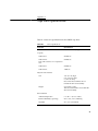
1
8505XL 8-mm Tape Drive
Owner’s Guide
Document Number 007-3086-001
CONTRIBUTORS
Written by Pablo Rozal
Illustrated by Dan Young and Cheri Brown
Edited by Christina Cary
Production by Derrald Vogt
Engineering contributions by Roy Hughes, Robert Clark, Dale Witt, Bill Yergin
Cover design and illustration by Rob Aguilar, Rikk Carey, Dean Hodgkinson,
Erik Lindholm, and Kay Maitz
© Copyright 1995 Silicon Graphics, Inc.— All Rights Reserved
This document contains proprietary and confidential information of Silicon
Graphics, Inc. The contents of this document may not be disclosed to third parties,
copied, or duplicated in any form, in whole or in part, without the prior written
permission of Silicon Graphics, Inc.
RESTRICTED RIGHTS LEGEND
Use, duplication, or disclosure of the technical data contained in this document by
the Government is subject to restrictions as set forth in subdivision (c) (1) (ii) of the
Rights in Technical Data and Computer Software clause at DFARS 52.227-7013
and/or in similar or successor clauses in the FAR, or in the DOD or NASA FAR
Supplement. Unpublished rights reserved under the Copyright Laws of the United
States. Contractor/manufacturer is Silicon Graphics, Inc., 2011 N. Shoreline Blvd.,
Mountain View, CA 94043-1389.
IRIX and Silicon Graphics are registered trademarks and CHALLENGE and Onyx
are trademarks of Silicon Graphics Corporation.
EXATAPE is a trademark of of Exabyte Corporation.
8505XL 8-mm Tape Drive Owner’s Guide
Document Number 007-3086-001
Contents
List of Figures v
List of Tables vii
About This Guide ix
Typographical Conventions
1.
x
Installation 1
Products that Support the 8505XL 1
Preparing for Installation 2
Ensuring ESD Protection 2
Unpacking the Tape Drive and Saving the Materials 3
Checking the Tape Drive Accessories 3
Installing the Tape Drive 3
Setting the SCSI ID 3
Configuring the Drive Sled for Single-Ended Operation 7
Terminating the SCSI Bus 8
Installing the Tape Drive 8
Installing Into a Horizontal Drive Bay 9
Installing Into a Vertical Drive Bay 9
Turning On Power to the Tape Drive 12
Installing Your Driver Software 12
Testing Your Installation 12
iii
Contents
2.
3.
iv
Operating the Tape Drive 17
Reading the LEDs 17
Selecting Data Cartridges 19
Write-Protecting a Data Cartridge
Loading a Data Cartridge 20
Unloading a Data Cartridge 21
Resetting the Tape Drive 21
20
Preventive Maintenance 23
Recommended Cleaning Cartridges 23
Determining When to Clean the Tape Drive
Using the Cleaning Cartridge 24
Caring for Data Cartridges 25
Replacing Data Cartridges 26
4.
Troubleshooting 27
Problems With Tape Drive Installation 27
Problems With Tape Drive Operation 28
A.
Tape Drive Specifications 31
23
List of Figures
Figure 1-1
Figure 1-2
Figure 1-3
Figure 1-4
Figure 1-5
Figure 1-6
Figure 1-7
Figure 2-1
Figure 2-2
Removing/Installing the Drive From/On the Drive Sled 5
Setting the SCSI ID (Default Setting Shown) 6
Setting the Drive Sled for Single-Ended Operation 8
Installing the Tape Drive Into a Horizontal Drive Bay 10
Installing the Tape Drive Into a Vertical Drive Bay 11
Write-Enable/Disable Switch 13
Loading a Data Cartridge 14
8505XL Front Panel 18
Unload Button 21
v
vi
List of Tables
Table 1-1
Table 2-1
Table 2-2
Table A-1
Problems and Possible Solutions 15
LED States and Interpretations 18
8505XL Tape Capacity 19
Drive Specifications 31
vii
viii
About This Guide
This guide helps you set up, install, and operate the 8505XL tape drive. The
8505XL uses 8-mm format tapes and installs in most of the existing Silicon
Graphics© systems and data storage units that support single-ended,
front-loading drives (FLDs).
Note: For a list of products that currently support the 8505XL tape drive, see
“Products that Support the 8505XL” on page 1.
This document is organized as follows:
Chapter 1
“Installation” describes how to install the drive and test the
installation.
Chapter 2
“Operating the Tape Drive” shows how to read the drive
LEDs, select tape cartridges, and load or unload tapes.
Chapter 3
“Preventive Maintenance” describes how and when to
clean the tape drive.
Chapter 4
“Troubleshooting” provides suggestions on solving tape
drive problems.
Appendix A
“Tape Drive Specifications” lists the physical,
environmental, electrical, and performance specifications
for the 8505XL.
ix
About This Guide
Typographical Conventions
These type conventions and symbols are used throughout this guide:
Italics
Filenames, variables, IRIX® command arguments, command flags, titles of
publications, icon names.
Screen type
Code examples, file excerpts, and screen displays (including error messages).
Bold Screen type
User input.
x
()
(Parentheses) Following IRIX commands, they surround the reference page (man
page) section where the command is described. For example, grep (1).
[]
(Brackets) Surround optional syntax statement arguments.
#
IRIX shell prompt for the superuser (root).
Chapter 1
1.
Installation
This chapter provides information for the following tasks:
•
preparing for installation
•
installing the tape drive
•
installing the software driver
Note: The 8505XL requires either IRIX 5.3, 6.1 or later software. If your
system already has IRIX 6.1, software driver installation is not required.
•
testing your installation
To install the tape drive properly, follow all of the instructions in this chapter.
You can use the checklist at the beginning of each section to keep track of the
steps you need to perform.
Caution: The tape drives described in this manual are single-ended SCSI
devices. Do not install the tape drive on a differential SCSI bus.
Products that Support the 8505XL
The 8505XL currently installs in the following Silicon Graphics systems and
data storage units:
•
CHALLENGE™ and POWER CHALLENGE XL (rackmount) and L
(deskside) systems
•
Onyx and POWER Onyx™ rackmount and deskside systems
•
CHALLENGE Vault XL
•
CHALLENGE Vault L
•
CHALLENGE S
1
Chapter 1: Installation
Preparing for Installation
To prepare for installation, follow the steps described in this chapter.
1.
Ensure ESD protection (see “Ensuring ESD Protection” on page 2).
2.
Unpack the tape drive and save the packing materials (see “Unpacking
the Tape Drive and Saving the Materials” on page 3).
3.
Check the tape drive accessories (see “Checking the Tape Drive
Accessories” on page 3).
Ensuring ESD Protection
If you are installing an internal tape drive, follow these procedures to protect
the tape drive from electrostatic discharge (ESD):
2
•
Attach a ground strap to your wrist when connecting/disconnecting
the drive.
•
Do not disconnect the power cord from the wall socket and the chassis if
you are servicing a system or installing a hardware upgrade. You will
lose the system ground and could damage the equipment as a result.
•
Ensure that you and all electrical equipment that you handle during
this installation are at ground potential to avoid damage from ESD.
•
Leave the tape drive in its antistatic bag until you are ready to install it.
When possible, remove the internal tape drive from its bag and install it
directly into the computer without setting it down. If you must lay the
tape drive down, place it on top of the antistatic bag or mat.
•
If possible, use an antistatic mat and grounded static protection
wristband. If a mat and wristband are unavailable, touch a known
grounded surface (such as your computer’s metal chassis) to discharge
static electricity from your body before handling the tape drive.
•
Limit your movement. Movement can cause static electricity to build
up around you.
•
Handle the tape drive carefully and by the edges.
•
Do not place the tape drive on top of the computer or on a metal table.
Installing the Tape Drive
Unpacking the Tape Drive and Saving the Materials
Carefully remove the tape drive from its box. Save all the original packaging
materials in case you need to reship the tape drive. The tape drive’s
packaging helps protect the tape drive from shock, vibration, moisture, and
electrostatic discharge (ESD).
Checking the Tape Drive Accessories
The 8505XL includes the following items:
•
tape drive
•
160-meter XL cartridge tape
•
cleaning tape
•
SCSI ID jumpers
•
software CD
Installing the Tape Drive
Installing your tape drive requires the following general tasks:
1.
Set the SCSI ID.
2.
Install the tape drive in an empty drive bay.
3.
Power on the tape drive.
4.
Install your software driver, if required.
5.
Test your installation.
Setting the SCSI ID
Each device attached to a SCSI bus must have a unique address or SCSI ID.
This SCSI ID, which can be a value from 0 through 7, allows the host
computer to communicate with the specific devices attached to the bus.
3
Chapter 1: Installation
Before setting the tape drive’s SCSI ID, determine the SCSI IDs of all the
other SCSI devices currently attached to your bus (for example, a hard drive
or a CD-ROM reader).
Caution: SCSI ID 0 is reserved for the system controller and cannot be used.
The tape drive is shipped with the SCSI ID set to 6. If you are installing the tape
drive on an existing SCSI bus and another device (for example, a hard drive)
is already assigned to that ID, you must change the tape drive’s ID.
Follow these steps to change the SCSI ID of the 8505XL:
Note: The 8505XL SCSI jumpers are located in the back of the drive and are
covered by the drive sled hardware. To change the SCSI ID, you must
remove the 8505XL from the drive sled.
4
Installing the Tape Drive
1.
Remove the four screws that secure the drive to the bottom of the
mounting sled (see Figure 1-1) and set them aside.
Exabyte drive
Power
connector
Data
connector
cable
A
Drive sled
SCSI channel
adapter board
Figure 1-1
Removing/Installing the Drive From/On the Drive Sled
2.
Remove the drive adapter and power cables from the 8505XL (see
Figure 1-1) and then place the drive on an anti-static surface.
3.
Locate the SCSI ID jumper block on the back of the tape drive (see
Figure 1-2).
5
Chapter 1: Installation
1
3
5
2
4
6
SCSI ID
0
1
2
3
4
5
6
7
Figure 1-2
4.
Setting the SCSI ID (Default Setting Shown)
Using a pair of flat-nose pliers, slide the small plastic jumpers over the
pins on the jumper block to obtain the desired address. Extra jumpers
are shipped in a separate bag. Save the unused jumpers in case you
need to select a different SCSI ID later.
Caution: Do not allow loose jumpers to fall inside the tape drive.
6
5.
After changing the SCSI ID, place the tape drive back on the drive sled
(see Figure 1-1).
6.
Reconnect the drive adapter and power cables (see Figure 1-1).
Installing the Tape Drive
7.
Install the four screws that secure the bottom of the drive to the drive
sled (see Figure 1-1).
Configuring the Drive Sled for Single-Ended Operation
The 8505XL drive sled assembly houses a SCSI channel adapter board. You
must ensure that the drive sled assembly is set to single-ended operation.
Caution: Use proper handling and storage procedures to minimize the loss
of data and equipment. In particular, do not remove disk drives while they
are operating. Always power off the system before removing a front-loading
drive (FLD). Be sure to use standard electrostatic discharge prevention
precautions when removing, storing, transporting, or replacing an FLD.
To determine the sled board settings, do the following:
•
Be sure the sled-to-drive connector cable is plugged into the correct
SCSI channel. Single-ended is A; differential is B. Plug the cable to
channel A (see Figure 1-3).
•
Set both jumper blocks H1 and H2 on the sled board to reflect the SCSI
channel operation, regardless of which channel is plugged into the
drive.
7
Chapter 1: Installation
Single−ended, 50−pin SCSI drive on channel A
No jumpers set;
reserved for future use.
B
A
A
Channel A =
single−ended
H1
H2
A
Figure 1-3
B
Channel B =
differential
Setting the Drive Sled for Single-Ended Operation
Note: Your system disk should always be set to SCSI ID 1. Be sure each SCSI
device on a bus has a unique SCSI address (ID). The SCSI bus cannot
function properly if more than one device has the same SCSI ID.
Terminating the SCSI Bus
The internal SCSI channels in a rackmount or deskside system and a data
storage unit are configured so that front-loading devices (FLDs) can be
added or removed without affecting the channel termination. No additional
termination is required.
Installing the Tape Drive
The drive must be properly mounted on a drive sled and configured for a
channel and single-ended operating protocol, as described in “Configuring
the Drive Sled for Single-Ended Operation” on page 7.
8
Installing the Tape Drive
Follow these instructions to install a half-height front-loading device:
Installing Into a Horizontal Drive Bay
Follow these instructions to install the drive into a horizontal drive bay.
1.
Orient the FLD and sled assembly so that the connectors on the back are
on the bottom half of the drive and face away from you (see Figure 1-4).
2.
Carefully insert the device into the drive bay until it seats firmly into
the lever catch and the locking lever has moved all the way to the right.
Installing Into a Vertical Drive Bay
Follow these instructions to install the drive (sideways) into a vertical drive
bay.
1.
Orient the FLD relative to the drive bay so that the drive is facing
toward the right (see Figure 1-5).
2.
Select a vacant drive bay and carefully align the rails on the drive sled
with the corresponding rails in the drive bay.
3.
Slide the FLD into the bay until the locking mechanism is engaged and
the locking lever on the drive sled moves down to the locked position.
Push the lever down to ensure that it is fully engaged.
9
Chapter 1: Installation
Slide drive lever
left to lock sled
Drive lever in
locked position
Figure 1-4
10
Installing the Tape Drive Into a Horizontal Drive Bay
Installing the Tape Drive
Drive sled
Drive
Figure 1-5
Installing the Tape Drive Into a Vertical Drive Bay
11
Chapter 1: Installation
Turning On Power to the Tape Drive
When power is applied to the 8505XL, watch for the following:
•
All three of the tape drive’s LEDs light.
•
The tape drive’s 30-second power-on self-test begins.
•
When the self-test is complete, the top and bottom LEDs turn off; the
middle LED is off or flashes irregularly.
Caution: Do not insert a data cartridge into the tape drive during the
self-test. The tape drive will eject it. If the top LED does not go out after the
self-test, an error has occurred. Contact your service provider for further
assistance.
Installing Your Driver Software
The 8505XL requires IRIX 5.3, 6.1, or later software for proper operation. If
your system has IRIX 5.3, an 8505XL software driver from a CD must be
installed. If your system has IRIX 6.1 or later software, no additional driver
software is required. See the software release notes for further information
on installing software.
Testing Your Installation
After installing your tape drive and driver software (if required), check the
installation by performing a simple backup and restore operation to verify
that your software and tape drive are communicating properly before you
begin operation.
Note: If this is the first time you have used the tape drive or if the tape drive
has been stored for six months or more, repeat steps 4 and 5 of the following
procedure at least two times or for two hours (whichever is greater).
To check the installation, follow these steps:
12
Installing the Tape Drive
1.
Locate a data cartridge that does not contain any valuable information
and make sure that its write-protect switch is set to write-enable (see
Figure 1-6).
2.
Gently push the data cartridge as shown (in Figure 1-7) until the load
mechanism pulls the cartridge into the drive.
RE
SA
RE
C
SA
VE
Write enable
Figure 1-6
C
VE
Write protect
Write-Enable/Disable Switch
13
Chapter 1: Installation
Figure 1-7
3.
14
Loading a Data Cartridge
Wait while the tape drive loads the tape, determines the tape format,
and positions the tape to the logical beginning of the tape (LBOT). This
takes about 45 seconds. When the green LED is on solid, the tape drive
is ready.
Installing the Tape Drive
4.
Perform a backup operation to write a small amount of data to the tape
(see your IRIX administration documentation, as required).
5.
Rewind the tape and read the data written in step 4 and compare it to
the original. This determines whether the software and tape drive are
functioning properly.
If problems occur, see Table 1-1.
Table 1-1
Problems and Possible Solutions
Problem
Corrective action
The tape drive does not successfully read Check the following:
and write data.
—Are you using the correct type of data
cartridge (see “Selecting Data
Cartridges” on page 19).
—Is the data cartridge write enabled?
—Is your software correctly installed
and configured?
—Press the unload button and remove
the data cartridge. Repeat steps 2
through 5 (see “Checking the Tape Drive
Accessories” on page 3) using a different
data cartridge. If the error occurs again,
refer to Chapter 4.
The tape drive’s LEDs are on or flashing. See Chapter 2.
You are unable to resolve the problem
yourself.
See your service provider.
15
Chapter 1: Installation
16
Chapter 2
2.
Operating the Tape Drive
This section includes information about the following:
•
reading the tape drive’s LEDs
•
selecting data cartridges
•
setting the write-protect switch on the data cartridge
•
loading and unloading a data cartridge
Reading the LEDs
The tape drive uses three LEDs (Figure 2-1) to indicate its operating states.
The LEDs indicate the following general conditions:
•
When the top (orange) LED is flashing, the tape drive has an error or
needs cleaning.
•
When the middle LED is on or flashing, SCSI bus activity is occurring.
The middle LED can be orange or green as follows:
•
Orange
The tape loaded in the tape drive is in one of the
compression formats (8500c or 8200c). When the tape is
8500c format, the LED is always orange even though
compression can be turned off.
Green
The tape loaded in the tape drive is in one of the
non-compression formats (8500 or 8200).
When the bottom (green) LED is on, a data cartridge is loaded in the
tape drive. When this LED is flashing, the tape is moving or the tape
drives needs cleaning.
Table 2-1 shows a specific combination of LEDs that may occur during tape
drive operation and the tape drive states that they indicate.
17
Chapter 2: Operating the Tape Drive
Unload button
Error indicator (orange)
SCSI bus activity indicator
(green or orange)
Tape motion indicator
(green)
Figure 2-1
8505XL Front Panel
Note: You may occasionally observe LED combinations and sequences not
described in Table 2-1. These other combinations represent special or
unusual conditions that are beyond the scope of this table.
Table 2-1
18
LED States and Interpretations
LED State
Top LED (errors)
Middle LED (SCSI)
Bottom LED
(motion)
Self-test start
On
On (green)
On
Self-test end
On
Flashing
(irregularly)
Off
Self-test fails
Flashing (fast)
Flashing
(irregularly)
Off
Ready (no tape)
Off
Flashing
(irregularly)
Off
Ready (tape)
Off
Flashing
(irregularly)
On
Normal tape
motion
Off
Flashing
(irregularly)
Flashing (slowly)
High-speed tape
motion
Off
Flashing
(irregularly)
Flashing (fast)
SCSI bus reset
On
Flashing
(irregularly)
On
Selecting Data Cartridges
Table 2-1 (continued)
LED States and Interpretations
LED State
Top LED (errors)
Middle LED (SCSI)
Bottom LED
(motion)
Error
Flashing (slowly)
Flashing
(irregularly)
Off
Time to clean
Flashing (fast)
Flashing
(irregularly)
Flashing (fast)
Note: The LEDs flash at different speeds to distinguish between states:
•
slow flash = 1 flash/second
•
fast flash = 4 flashes/second
•
Irregular flash = rate of flash varies with SCSI bus activity. If the device
is not connected to the bus, the LED is off.
Selecting Data Cartridges
Silicon Graphics recommends that you use EXATAPE™ 8-mm data
cartridges from Exabyte Corporation.
Caution: Always use data-grade media data cartridges. Never use
video-grade tape for data storage. Video-grade tape can be less accurate than
data-grade tape when recording high-density data. The video-grade tape is
also more abrasive to tape-drive recording heads.
The 8505XL drive supports 15-m, 54-m, 112-m, and 160-m XL tapes (see
Table 2-2).
Table 2-2
8505XL Tape Capacity
Data Cartridge
Capacity
15 m
1.2 GB
54 m
4.8 GB
112 m
10 GB
160 m XL (see Note)
14 GB
19
Chapter 2: Operating the Tape Drive
Note: The EXATAPE 160-m XL data cartridges contain a recognition system
stripe located on the tape leader for media identification. The 8505XL uses
this stripe to distinguish data-quality metal-particle media, such as
EXATAPE, from other 160-m media.
To maintain data integrity, the 8505XL automatically ejects 160-m data
cartridges or equivalent length video cartridges that are not equipped with
the recognition system stripe.
Write-Protecting a Data Cartridge
Before loading a data cartridge in the tape drive, make sure that the
write-protect switch on the cartridge is set correctly for the desired operation
(see Figure 1-6 in Chapter 1). You can use a ball-point pen or similar
instrument to set the write-protect switch, as shown.
Loading a Data Cartridge
To load a data cartridge into the tape drive, follow these steps:
20
1.
Make sure that the write-protect switch has been set correctly for the
desired operation, as explained on “Write-Protecting a Data Cartridge”
on page 20.
2.
If you have just turned on your system, be sure that the bottom and top
LEDs are off, indicating that the tape drive has passed its power-on
self-test and is ready to load the data cartridge.
3.
Gently push the data cartridge into the tape drive (see Figure 1-7 in
Chapter 1) until the load mechanism pulls the data cartridge into the
tape drive.
Unloading a Data Cartridge
Unloading a Data Cartridge
The unload button is the only operating control on the tape drive. It is used
to unload the data cartridge from the tape drive (see Figure 2-2).
Note: You can use the unload button to clear some hardware errors. If a
hardware error occurs, press the unload button to reset the tape drive.
To unload a data cartridge, press the unload button. The tape drive
completes the current operation, writes any buffered data to tape, rewinds
the tape, unloads the tape from the tape path, and ejects the cartridge.
Unload
button
Figure 2-2
Unload Button
Note: If an error occurs before or during the unload procedure, the unload
sequence will be suspended and the orange LED will flash. To clear the error,
press the unload button again. The unload sequence will be reattempted.
However, unwritten data in the buffer will not be written to the tape. The
buffer and errors will be cleared.
Resetting the Tape Drive
Occasionally the tape drive may experience an error that cannot be cleared
by pressing the unload button. If this happens, reset the tape drive by
turning the power off, then on again.
Caution: Powering off the tape drive may reset the SCSI bus. To prevent
possible loss of data, make sure that any other devices on the SCSI bus are
inactive and have completed all requested operations before powering off
the tape drive.
21
Chapter 2: Operating the Tape Drive
22
Chapter 3
3.
Preventive Maintenance
The only routine maintenance required by the tape drive is regular cleaning
of the tape drive heads and tape path. Proper storage and maintenance of
your data cartridges maximizes the shelf life of your tapes and assures data
integrity.
Recommended Cleaning Cartridges
Silicon Graphics recommends that you clean your tape drive with the
Exabyte 8 mm cleaning cartridge (supplied with your package) or an
Exabyte-approved cartridge. Using this cleaning cartridge regularly allows
you to maintain data integrity and improve reliability of the tape drive.
Caution: Using a cleaning method or cleaner other than the recommended
brand can void the tape drive warranty and possibly lead to premature wear
of the recording head.
Determining When to Clean the Tape Drive
You should clean the tape drive’s heads either once a month or after every
30 tape motion hours (or more frequently if you are operating in a
particularly dirty environment).
The tape drive keeps track of its tape motion hours internally. When 30 tape
motion hours have elasped, the top and bottom LEDs will flash rapidly and
the middle LED will flash irregularly, depending on SCSI bus activity. For
best results, clean the tape drive as soon as possible after the LEDs begin
flashing. Table 2-1 in Chapter 2 describes the LED pattern indicating that the
tape drive needs cleaning.
23
Chapter 3: Preventive Maintenance
Using the Cleaning Cartridge
To use the cleaning cartridge, follow these steps:
1.
Make sure that the tape drive is on and has run the power-on self-test in
Table 2-1 in Chapter 2.
2.
Remove any data cartridge from the tape drive.
3.
Check the cleaning cartridge to see if there is sufficient cleaning
material remaining on the supply reel. If there is no cleaning material
remaining, discard the cleaning cartridge and use a new one.
The 8505XL ships with a cleaning cartridge that can be used for up to
nine cleanings.
Caution: Do not rewind and reuse the cleaning cartridge. Reusing a
cleaning cartridge redistributes contaminants previously removed from
the tape path.
4.
Insert the cleaning cartridge into the tape drive. The cleaning cycle is
performed automatically by the tape drive and takes from 2 to 3
minutes. When the cleaning cycle is complete, the cleaning cartridge is
automatically unloaded and ejected from the tape drive.
Note: If there are no more cleaning cycles remaining for the cleaning
cartridge, the tape drive ejects it without completing the cleaning cycle.
24
5.
Confirm that a cleaning was done. Look at the LEDs on the front of the
tape drive. If the cleaning cycle was successful, the top and bottom
LEDs will be off. If the cleaning cycle was not performed, the LEDs will
continue to flash.
6.
Store the cleaning cartridge for future use if it still has cycles remaining.
Or, discard it if no more cleaning cycles remain. You may want to
maintain a record of how many times the cleaning cartridge has been
used.
Caring for Data Cartridges
Caring for Data Cartridges
To maximize the shelf life of your tapes and assure data integrity, follow
these guidelines when storing data cartridges:
•
Place a label or other reference information on the cartridge adjacent to
the write-protect switch. On the label, you may want to include the
cartridge number (log number), date of backup, and format of the tape.
•
Keep cartridges in their protective boxes when not in use.
•
Do not open the cartridge’s access door or touch the tape.
•
Store cartridges in a cool, non-magnetic environment. Follow the
cartridge manufacturer’s specifications for storage temperature and
other environmental requirements. Do not allow the temperature and
humidity in the storage environment to fluctuate.
•
Keep the storage location as free of airborne particulates as possible. To
eliminate obvious sources of particulates, do not permit anyone to
smoke, eat, or drink near the storage area, and do not store cartridges
near a copier or printer that may emit toner and paper dust.
•
Store data cartridges as soon as possible after you have written data to
them. Immediate storage helps avoid many of the conditions that can
damage tapes, such as temperature and humidity fluctuation,
particulate contamination, and excessive handling.
•
Store data cartridges with the write-protect switch in the protected
position (see “Write-Protecting a Data Cartridge” on page 20).
•
Store each cartridge on one of its long edges, not flat on its side. When a
data cartridge is stored on its side, the tape inside the cartridge is
actually on its edge. In this position, stress is placed on the tape edges
and can lead to tape damage. For the same reason, never stack
cartridges on top of each other or lean them at an angle for extended
periods of time.
25
Chapter 3: Preventive Maintenance
Replacing Data Cartridges
Approximately once each year, you may want to read all information on a
tape and check the read error statistics. If errors have increased significantly
since the previous test or if they exceed a certain predetermined threshold,
you should rearchive the data to a new tape and discard the old tape.
26
Chapter 4
4.
Troubleshooting
This chapter provides suggestions for solving problems that may occur
when you are installing and operating your tape drive. These suggestions
are divided into the following sections:
•
problems with tape drive installation
•
problems with the tape drive operation
Often you can solve a tape drive problem by trying the steps recommended
here. If your problem persists, contact your service provider.
Problems With Tape Drive Installation
Most problems during installation occur because the SCSI bus or the backup
software is not correctly configured. If your tape drive and backup software
are not communicating after installation or your software reports a
hardware error, check the following:
•
Make sure that all devices on the SCSI bus are single ended.
•
Make sure that the SCSI ID you selected for the tape drive is not the
same as the ID used by another SCSI device (see “Setting the SCSI ID”
on page 3).
•
If you have IRIX 5.3, make sure that the additional driver software is
installed on the system. IRIX 6.1 software already has the 8505XL driver
in place.
After checking all the items listed, reset the SCSI bus by resetting the system.
Caution: To prevent possible loss of data, make sure that any other devices
on the SCSI bus are inactive and have completed all requested operations
before powering off the tape drive or resetting the bus.
27
Chapter 4: Troubleshooting
Problems With Tape Drive Operation
Most problems with tape drive operation occur with improper cartridge use.
If you have been successfully operating your backup software and tape
drive in the past, but are now experiencing problems reading and writing
data, check the following:
•
If you are writing data, make sure that the data cartridge is write
enabled.
•
Check the brand of data cartridge you are using. Silicon Graphics
recommends using EXATAPE data cartridges (see “Selecting Data
Cartridges” on page 19).
Note: When selecting extended-length tapes for XL tape drives, only
use EXATAPE 160-m XL 8 mm data cartridges. Any other type of
extended-length tape may be automatically ejected (see “Selecting Data
Cartridges” on page 19).
28
•
Make sure that you are inserting the data cartridge correctly.
•
If the data cartridge has been in use for a long time or has been used
frequently, try using a new data cartridge.
•
Determine whether the tape drive needs cleaning (see “Determining
When to Clean the Tape Drive” on page 23).
Problems With Tape Drive Operation
If you are experiencing operating problems loading or unloading a data
cartridge, check the following:
•
Make sure that your system is turned on. If the system is off, the tape
drive may not eject the data cartridge.
•
The tape drive may have experienced a hardware error. Press the
unload button to clear the error, then try loading the data cartridge
again.
Caution: The first time you load a data cartridge after clearing an error,
use a data cartridge with no valuable information on it. Make sure that
the tape drive can successfully unload the data cartridge before
resuming operation.
•
If the data cartridge still will not unload, power off your system, then
reboot to reset the SCSI bus.
Caution: To prevent possible loss of data, make sure that any other
devices on the SCSI bus are inactive and have completed all requested
operations before powering off the system to reset the SCSI bus.
29
Chapter 4: Troubleshooting
30
Appendix A
A.
Tape Drive Specifications
Table A-1 shows the specifications for the 8505XL tape drive.
Table A-1
Drive Specifications
Parameter
Specifications
Interface
SCSI-1 and SCSI-2, single-ended
Capacity
8200 format
262 KB/sec
8200c format
500 KB/sec
Note: This assumes a 2:1 compression
ratio
8500 format
500 KB/sec
8500c format
1 MB/sec
Physical Characteristics
Size
1.62” (4.1 cm) high
5.75” (14.6 cm) wide
8” (20.3 cm) deep
Note: These measurements do not
include the drive sled assembly.
Weight
2.6 pounds (1.2 kg)
This measurement does not include the
drive sled assembly.
Environmental
Ambient temperature
5˚ to 40˚ C * (41˚ F to 104˚F)
Relative Humidity (operating)
20% to 80%, non-condensing
Wet bulb
25˚ C (75˚ F) maximum
31
Appendix A: Tape Drive Specifications
Table A-1 (continued)
Drive Specifications
Parameter
Specifications
Power and Reliability
32
Input voltages
Standard + 5 VDC and +12 VDC 5%
Power consumption
14.5 W
Mean time between failure
160,0000 hours at 10% duty cycle