1
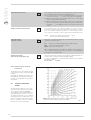
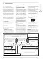
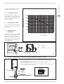
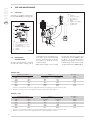
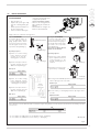
CONTENTS
1
DESCRIPTION OF THE BOILER . . . . . . . . . . . . . . . . . . . . . . . . . . . . . . . . . . . . . . . . . . . . . . . . . . . . . . . . . . . . . . . . . pag. 102
2
INSTALLATION . . . . . . . . . . . . . . . . . . . . . . . . . . . . . . . . . . . . . . . . . . . . . . . . . . . . . . . . . . . . . . . . . . . . . . . . . . . . . . . pag. 104
3
CHARACTERISTICS . . . . . . . . . . . . . . . . . . . . . . . . . . . . . . . . . . . . . . . . . . . . . . . . . . . . . . . . . . . . . . . . . . . . . . . . . . . pag. 111
4
USE AND MAINTENANCE . . . . . . . . . . . . . . . . . . . . . . . . . . . . . . . . . . . . . . . . . . . . . . . . . . . . . . . . . . . . . . . . . . . . . pag. 114
IMPORTANT
When carrying out commissioning of the boiler, you are highly recommended to perform the following checks:
– Make sure that there are no liquids or inflammable materials in the immediate vicinity of the boiler.
– Make sure that the electrical connections have been made correctly and that the earth wire is connected to a
good earthing system.
– Open the gas tap and check the soundness of the connections, including that of the burner.
– Make sure that the boiler is set for operation for the type of gas supplied.
– Check that the flue pipe for the outlet of the products of the combustion is unobstructed and has been properly installed.
– Make sure that any shutoff valves are open.
– Make sure that the system is charged with water and is thoroughly vented.
– Check that the circulating pump is not locked.
– Purge the system, bleeding off the air present in the gas pipe by operating the pressure relief valve on the gas
valve inlet.
FONDERIE SIME S.p.A. of Via Garbo 27 - Legnago (VR) - Italy declares that its hot water boilers, which bear the
CE mark under Gas Directive 90/396/CEE and are fitted with a safety thermostat calibrated to a maximum of
110°C, are not subject to application of PED Directive 97/23/CEE as they meet the requirements of article 1
paragraph 3.6 of the Directive.
PLANET DEWY 60 BFR - ENGLISH
INSTALLER INSTRUCTIONS
1
DESCRIPTION OF THE BOILER
ES
1.1
INTRODUCTION
FR
“PLANET DEWY 60 BFR” boilers (supplied
as Class B devices) are pre-mixed condensation heating modules intended only for
IT
BE
1.2
GB
heating, designed to work singularly or in
sequence/cascade autonomously.
They are designed and constructed to
meet European directives 90/396/CEE,
89/336/CEE, 73/23/CEE, 92/42/CEE
and European regulation EN 483.
Upon request, a control unit for a maximum of four boilers can be supplied for
sequence/cascade installation.
DIMENSIONS
170
230
R C
75
S3
120
265
M
G
C.H. return
C.H. flow
Gas connection
Filling system
Condensation outlet
Inlet
Outlet
G 1 (UNI-ISO 228/1)
G 1 (UNI-ISO 228/1)
G 3/4” (UNI-ISO 228/1)
G 1/2” (UNI-ISO 228/1)
ø 25
ø 80
ø 80
60
275
120
=
409
=
870
865
20
55
R
M
G
C
S3
CA
CS
455
500
CS
CA
265
150
135
220
ATTENTION: the boiler is supplied as Class B device. To
install the boiler as Class C device, remove the terminal inserted in the flange before connecting the intake.
Fig. 1
1.3
MAIN COMPONENTS
8
9
7
6
10
11
5
12
13
4
14
3
KEY
1 Gas valve
2 Condensation drain siphon
3 Fan
4 Air pressure switch
5 Ignition electrode
6 Detection electrode
7 Ignition transformer
8 Exhaust thermostat
9 Heating probe (SM)
10 Safety thermostat 100°C
11 Differential pressure switch
12 Single-acting valve
13 Automatic escape
14 Pump
15 Control panel
16 Safety valve 4 BAR
2
15
1
16
102
Fig. 2
IT
1.4
ES
TECHNICAL FEATURES
PLANET DEWY 60 BFR
Heat output nominal (80-60°C)
Heat output nominal (50-30°C)
Heat output minimum G20 (80-60°C)
Heat output minimum G20 (50-30°C)
Heat output minimum G31 (80-60°C)
Heat output minimum G31 (50-30°C)
kW (kcal/h)
kW (kcal/h)
kW (kcal/h)
kW (kcal/h)
kW (kcal/h)
kW (kcal/h)
56,6 (48.600)
62,1 (53.400)
17,0 (14.600)
19,0 (16.300)
22,6 (19.500)
25,4 (21.800)
Nominal heat output
Minimum heat output G20
Minimum heat output G31
kW (kcal/h)
kW (kcal/h)
kW (kcal/h)
58 (49.900)
17,4 (15.000)
23,2 (19.900)
%
%
%
97,5 - 97,6
107,0 - 109,3
109,8
Efficiency minimum/nominal output (80-60°C)
Efficiency minimum/nominal output (50-30°C)
30% yield (50-30°C)
Class NOx
CE certification
Category
Type
C.H.
Maximum water head
Maximum temperature
Water content boiler
C.H. setting range
GAS PRESSURE END NOZZLES
Gas supply pressure G20
Gas supply pressure G31
Nozzles quantity
Nozzles diameter G20
Nozzles diameter G31
Gas consumption nominal/minimum G20
Gas consumption nominal/minimum G31
WEIGHT
BE
GB
★★★★
Termal efficiency (CEE 92/42 directive)
Smokes temperature maximum (80-60°C)
Smokes temperature minimum (80-60°C)
Smokes temperature maximum (50-30°C)
Smokes temperature minimum (50-30°C)
Smokes flow
CO2 maximum/minimum G20
CO2 maximum/minimum G31
Maximum pressure exhaust manifold output
Adsorbed power consumption
Electrical protection grade
FR
5
°C
°C
°C
°C
kg/h
%
%
Pa
W
76
63
56
35
95,2
9,0/9,0
10,0/10,0
110
198
IPX4D
n°
1312BP4141
II2H3P
B23-53 / C13-33-43-53-83
bar
°C
l
°C
4
85
4,8
20/80
mbar
mbar
n°
ø
ø
m3/h
kg/h
kg
20
37
1
9,3
6,7
6,14/1,84
4,51/1,80
61
103
2
INSTALLATION
IT
ES
The boiler must be installed in a fixed location and only by specialized and qualified
firms in compliance with all instructions
contained in this manual.
Furthermore, the installation must be in
accordance with current standards and
regulations.
FR
BE
GB
2.1
BOILER ROOM
“PLANET DEWY 60 BFR” boilers can be
installed in boiler rooms whose size and
requirements meet current regulations.
Furthermore, vents ,with surface areas at
least 3.000 sq. cm or 5.000 sq. cm for
gas with density over 0.8, must be installed
in the outer walls for room ventilation.
kit is supplied with assembly and use
instructions.
2.3
2.2
INSTALLATION
For ins t allation f or single or
sequence/cascade operations, refer to the
example in fig. 3.
With control unit code 8096301, supplied
by Sime upon request, a maximum of four
boilers can be controlled. The control unit
CONNECTING UP SYSTEM
To protect the heat system from damaging
corrosion, incrustation or deposits, after
installation it is extremely important to
clean the system using suitable products
such as, for example, Sentinel X300 or
X400. Complete instructions are provided
with the products but, for further information, you may directly contact GE Betz.
WARNING: In both single and sequence/cascade installation, the
heating system must be equipped with a hydraulic separator and
safety components.
M
S3
G
R
R
M
G
S3
C.H. return
C.H. flow
Gas connection
Condensation outlet
Fig. 3
104
IT
For long-term protection agains corrosion
and deposits, the use of inhibitors such as
Sentinel X100 is recommended after cleaning the system. It is important to check
the concentration of the inhibitor after
each system modification and during maintenance following the manufacturer’s
instructions (specific tests are available at
your dealer). The safety valve drain must be
connected to a collection funnel to collect
any discharge during interventions.
WARNING: Failure to clean the heat
system or add an adequate inhibitor invalidates the device’s warranty.
Gas connections must be made in accordance with current standards and regulations. When dimensioning gas pipes from
the meter to the module, both capacity
volume (consumption) in m 3/h and gas
density must be taken into account.
The sections of the piping making up the
system must be such as to guarantee a
supply of gas sufficient to cover the maximum demand, limiting pressure loss
between the gas meter and any apparatus
being used to not greater than:
– 1.0 mbar for family II gases (natural gas);
– 2.0 mbar for family III gases (butane or
propane).
A sticker inside the module includes identification and gas type data specific to the
module.
civil drain by a pipe with minimum 5 mm
per meter gradient for condensation collection.
Only normal plastic civil drain pipes are
suitable to convey condensation to the
building's sewer drain.
2.3.2
The gas valve has a standard input filter
which, in any case, is not capable of filtering
all the impurities contained in the gas and
mains piping.
To prevent poor valve operations or in certain cases, excluding the valve's safety features, we recommend installing a suitable filter on the gas pipe.
2.5
2.6
EXHAUST
The boiler comes with a ø 80 rubber
washer to be installer in the waste pipe (11
fig. 4-4/a).
2.6.2
BE
GB
Type B
If the inlet is not connected, the boiler
should be regarded a Class B device.
Type C
The boiler becomes a Class C device when
the intake terminal is removed from the
flange and the intake is connected to separate exhaust ducts (fig. 4).
It is also possible to place the exhaust on a
roof using a concentric stack (ø 80/125)
and the manifold shown in Figure 4/a.
2.7
Condensation drain installation.
A siphoned drain must be connected to the
FR
FILLING THE SYSTEM
Cold system filling pressure must be 1 bar.
The system must be filled slowly so that air
bubbles are released through the specific
escapes.
2.6.1
2.3.1
Gas pipe filter
ES
When installing the boiler in locations
where it needs to be protected from water,
replace the intake terminal inserted in the
flange with terminal code 8089510.
For information on how to configure the
boiler in this mode see figure 4.
When the boiler operates at low temperatures, normal flues can be used at the following conditions:
- The flue must not be used by other boilers.
- The inside of the flue must be protected
from direct contact with boiler condensation. Combustion products must be
conveyed with a flexible pipe or rigid plastic pipe with a diameter of approximately 100 - 150 mm siphon draining condensation at the foot of the pipe. Siphon
working height must be at least 150
mm.
ELECTRICAL CONNECTION
The boiler is supplied with an electric cable.
Should this require replacement, it must be
purchased exclusively from SIME.
The electric power supply to the boiler must
Type C
Type B
KEY
1
2a
2b
3
4
5
6
7
8
9
11
90° MF polypr. curve (6 pcs.) code 8077450
Polypr. extension L.1000 (6 pcs.) code 8077351
Polypr. extension L. 500 (6 pcs.) code. 8077350
Hinged tile code 8091300
Roof exit terminal L. 1381 cod. 8091204
Polypropylene extension L. 250
with test outlet code 6296513
45° MF polypr. curve (6 pcs.) code. 8077451
Exhaust terminal code 8089501
Internal-external ring nut kit code 8091500
Intake terminal (supplied as standard)
Rubber gasket ø 80 (supplied as standard)
ø 80 ACCESSORY LOAD LOSS TABLE
Load loss
(mm H2O)
90° MF polypropylene curve
45° MF polypropylene curve
Polypr. extension L. 1000 (horizontal)
Polypr. extension L. 1000 (vertical)
Roof exit terminal L. 1381
Exhaust terminal
Intake terminal
1,60
1,30
0,60
0,60
1,30
0,60
0,30
WARNING:
The maximum length of the exhaust pipe is calculated by the load losses of the single assembled accessories and must not be
greater than 11,2 mm H2O.
Before installing accessories, lubricate the internal part of gaskets with silicon-based products. Avoid using oils and greases.
Fig. 4
105
IT
ES
Type C
FR
BE
GB
KEY
2a
2b
3
4
5
6
10
11
Polypr. extension L.1000 (6 pcs.) code 8077351
Polypr. extension L. 500 (6 pcs.) code. 8077350
Hinged tile code 8091300
Roof exit terminal L. 1381 cod. 8091204
Polypropylene extension L. 250 with test outlet code 6296513
45° MF polypr. curve (6 pcs.) code. 8077451
Manifold code. 8091400
Rubber gasket ø 80 (supplied as standard)
ø 80 ACCESSORY LOAD LOSS TABLE
Load loss
(mm H2O)
45° MF polypropylene curve
Polypropylene extension L. 1000 (vertical)
Roof exit terminal L. 1381
Manifold
1,30
0,60
1,30
0,60
WARNING:
The maximum length of the exhaust pipe is calculated by the load
losses of the single assembled accessories and must not be greater than 11,2 mm H2O.
Before installing accessories, lubricate the internal part of
gaskets with silicon-based products. Avoid using oils and greases.
Fig. 4/a
be 230V - 50Hz single-phase through a
fused main switch, with at least 3 mm spacing between contacts.
Respect the L and N polarities and the
earth connection.
NOTE: SIME declines all responsibility for
injury or damage to persons, animals or
things, resulting from the failure to provide for proper earthing of the appliance.
2.7.1
Room stat connection
(fig. 8 pos. A)
To gain access to the electronic board connector (3), remove the control panel cover
and connect the room stat to the terminals
TA after having removed the jumper.
The thermostat or timer -thermostat,
recommended for better room temperature control, must be class II as specified by
standard EN 60730.1 (clean contact).
106
WARNING: Applying mains voltage to the
terminals of conector (3) will irreparably
damage the control board. Make sure
that any connections to be made are not
carrying mains voltage.
2.7.2
“Logica Remote Control”
connection (fig. 8 pos. B)
The electrical plant must comply with local
standards and all cables must comply with
low safety voltage requirements of EN
60730.
For lengths up to 25 m, use cables of section 0.25 mm2, for longer lengths up to 50
m use cables of section 0.5 mm2. First of
all, assemble and wire the socket (2), then
insert the equipment which will start-up as
soon as it receives current.
To gain access to connector (3) remove the
control panel cover and connect the climate
regulator to terminals CR.
WARNING: External voltage must not be
connected to terminals 1-2-3-4 of the
"Logica Remote Control". A telephone
remote switch with a zero potential contact or a window contact can be connected
to terminals 3-4.
Equipment for the checking of civil plants
via a telephone line includes the model
TEL 30.4 LANDIS & STAEFA.
2.7.3
External temperature
sensor connection (fig. 8 pos. C)
The cables must comply with low safety voltage requirements of EN 60730.
For lengths up to 25 m, use cables of section 0.25 mm2, for longer lengths up to 50
m use cables of section 0.5 mm2.
To gain access to boiler connector (3) remove the control panel cover and connect the
external temperature sensor to terminals
SE.
IT
ES
KEY
1 Control panel
2 “Logica Remote Control” socket
3 Conector (J2)
TA Room stat (not supplied)
CR Logica Remote Control (optional)
SE External temperature sensor (optional)
CRONOTERMOSTATO
ROOM
STAT
FR
BE
A
GB
3
LOGICA REMOTE
CONTROL
2
B
LOGICA REMOTE
CONTROL
SONDA
EXTERNAL SENSOR
ESTERNA
1
C
2.7.4
Fig. 8
Wiring diagram
J7
J5
J4
J3
J2
KEY
EV1
EV2
EA
ER
TS
V
TPA
PI
SE
TA
SM
TR
PD
CR
SV
OP
Gas valve coil
Gas valve coil
Ignition electrode
Detection electrode
Safety thermostat 100°C
Fan
Water pressure transducer
System pump
External probe (optional)
Room thermostat
Heating probe
230 - 24V transformer
Differential pressure switch
Remote Control Logic (optional)
Fan board
Programmer clock
TF
PA
SB
VD
TRA
Exhaust thermostat
Air pressure switch
Boiler probe
Shunt valve
Ignition transformer
NOTE: Connect the room thermostat (TA) to terminals 5-6
after removing the bridge. Fan control board (SV) “MAX” and
“MIN” trimmers are sealed and must never be tampered with.
CONNECTOR SPARE PART CODES:
J2 cod. 6278613
J3 cod. 6293591
J4 cod. 6293589
J5 cod. 6293586
J7 cod. 6293587
Fig. 9
107
IT
ES
2.8
FR
All the boiler's functions can be managed
by a optional digital multifunctional device
code 8092204 for the remote of the boiler itself and for regulating room climatic
conditions with an operational reserve of
12 hours.
The heating circuit is controlled by the room
temperature sensor built-in the equipment
or by the atmospheric conditions, with or
without environmental inflow, if the boiler is
connected to an external sensor.
BE
GB
LOGICA REMOTE CONTROL
Characteristics:
– Ergonomic control unit divided according
to function (control levels)).
– Clear division of basic functions:
• operating regime, correction of set
value and presence button are directly
accessible;
• Dif ferent real current values are
accessible through the "info" button;
• other functions can be programmed
after the cover has been opened;
• special service level with protected
access;
– Each setting or modification is displayed
and confirmed.
– Tome setting (special line for changing
BST/CET).
– Heating programme with max. 3 heating
periods per day, individually selectable.
– Copy function for easy transfer of heating programme to the next or pre-
vious day.
– Holiday programme: the programme is
interrupted for the holiday period and
automatically restarted on returning
home.
– Option to return the heating program to
default values.
– Programming lock (child safety).
Functions:
– Delivery temperature control guided by
the atmospheric conditions, taking into
account the dynamics of the building.
– Delivery temperature control guided by
atmospheric conditions with influence of
ambient temperature.
– Ambient temperature control only.
– Adjustable influence of ambient temperature shift .
– Switch-on and switch-off optimisation.
– Rapid lowering.
– ECO functions (daily heating limiter, automatic summer/winter switch-over).
– Controllable maximum delivery temperature limit (specifically for floor plants).
– Limitation of increase in pre-set delivery
temperature.
– Anti-freeze protection for buildings.
– Hourly programming of the tank unit
temperature on two levels: comfort and
reduced.
– Domestic hot water control with nominal
value requirement and enable.
– Connection to room sensor or switching
of operating regime through the telepho-
ne system with external contact or
through a window contact.
– Anti-bacterial.
2.8.1
Installation
The unit must be installed in the main living
room. For installation, follow the assembly
instructions inserted in the package. At this
point, with the selector knob on ( ), the
installer can adjust the basic parameters settings according to the individual needs (point
2.8.2). If there is a thermostatic radiator
valve fitted, this must be set to maximum.
2.8.2
Installation settings
The settings for the basic operating parameters for individual needs are reported in
the instruction leaflet supplied with the
"Logica Remote Control" and in the section
reserved for the user in this manual.
For further adjustments which can be carried out by the installer, the "Logica Remote
Control" offers a level of service and parameterising which can only be accessed
through a special combination of buttons.
To activate this level of service or parameterising press buttons
and
least 5
seconds. This will activate the parameterising level. Then use the same arrow buttons
to select the individual input lines and adjust
the values with
or
.
HEATING CIRCUIT SETTINGS
Antifreeze protection
"Pre-set ambient
temperature value"
51
Heating takes place up to this pre-set value if the plant is activated in standby
(e.g. holidays).
In this way, the building antifreeze function is active, preventing an excessive
lowering of the ambient.
Summer/Winter switch-over
temperature
52
This parameter regulates the temperature of the automatic summer/winter switch-over.
Type of control:
0 = with ambient influence
1 = without ambient influence
53
This parameter de-activates the ambient influence and as a result all the
optimisations and adaptations.
If a valid external temperature is not transmitted , the controller switches to
the pure ambient control guide variable.
Influence of ambient temperature
54
If the ambient controller is used only as a remote control (placed in the reference room and without an external sensor connected), the value must be
set at 0 (zero).
If the change in ambient temperature from the pre-set value remains high
during the entire day, the influence must be increased. If the ambient temperature is around the pre-set value (control oscillation), the influence must
be reduced.
Note: If the ambient temperature influence constant is set at 0, the adaptation of the heating curve is deactivated. In this case, parameter 57 will
have no effect at all.
108
IT
Maximum limit of delivery
temperature
55
The delivery temperature is limited to the maximum set value.
Variation of the maximum speed of the
delivery temperature
56
The increase per minute of the prescribed delivery temperature value sent
in °C is limited to the imposed value.
Activation of adaptation
57
With the activation of the adaptation, the pre-set value transmitted to the
boiler regulator is adapted to the effective heat need.
The adaptation functions with both the atmospheric guide with ambient
influence and with pure ambient control.
If the "Logica Remote Control" is set as a remote control only, the adaptation
must be is deactivated.
Optimisation of
switch-on time
58
If the switch-on time optimisation is active, the "Logica Remote Control" modifies the heating gradient until it finds the optimum heating point
0 = off
1 = on
Heating gradient
59
The "Logica Remote Control" selects the switch-on time such that the set
value has more or less been reached at the start of the usage time.
The more severe the night-time cooling, the earlier the heating time starts.
ES
FR
Example: Current ambient temperature
Nominal ambient temperature
Heating gradient
Presetting of switch-on time:
1.5 K x 30 min/K =
BE
GB
18.5°C
20°C
30 min/K
45 minutes
00 means that the switch-o time has not been pre-set (function disabled).
60
If the switch-off time optimisation is active (value > 0), the "Logica Remote
Control" modifies the pre-set time until it finds the optimum switch-off time..
Reduced domestic hot
water pre-set value
61
The reduced pre-set value of the temperature of the domestic hot water allow
the required water temperature to be obtained outside the programmed
usage times (daily programme 8).
Domestic hot water load
62
0 = 24 hours/ day - Hot water is always available at the temperature set
with user parameter n°3.
1 = standard - Hot water according to the daily heating programme.
In the comfort areas of heating the temperature of the boiler unit is regulated to the value set with user parameter n° 3.
In the reduced areas of heating the temperature of the boiler unit is
regulated to the value set with parameter n° 61 of the service level.
2 = service disconnected
3 = second daily programme (8) - Every day of the week the temperature of
the hot water is set according to programme 8. In this case there is a
single programming for all the days of the week and three time zones are
available. In the time spans set the temperature of the boiler unit is regulated according to that set in parameter n°3. In the remaining hours the
boiler unit is controlled to the temperature set with parameter n° 61 the
of service level.
63
This block (1) can be activated to display all the parameters without
modifying them. Pressing buttons
or
displays “OFF”.
Presetting switch-off
time (00 = off)
DOMESTIC HOT WATER SETTINGS
SERVICE VALUES
Final user level 2
programming block
WARNING:
The activation block can be deactivated temporarily by pressing buttons
and
simultaneously; a confirmation sign appears on the display.
At this point press simultaneously the buttons
and
for at least 5
seconds.
To permanently remove the activation block, set parameter 63 on 0.
109
IT
ES
Input function terminal 3-4
64
The freely programmable input (terminals 3-4) allows three different functions
to be activated. The parameter has the following significance:
1 = If an external sensor is connected, the display will show the temperature
of the external sensor ( _ _ = no sensor connected, function disabled).
2 = With an external contact, it is possible to switch-over to "reduced preset value of the ambient temperature".
3 = With an external contact, it is possible to switch-over to "reduced preset value of the antifreeze ambient temperature" (short circuit 0 0 0 or
interruption _ _ _ ). The display shows the current status of the external
contact.
Modo de acção do contacto externo
65
Se a entrada (bornes 3 e 4 do ropadé) está ligada a um contacto externo de
potencial zero (parâmetro 64 = 2 ou 3), pode ser determinado o modo de
acção do contacto (tele-interruptor do telefone ou contacto janela). O modo de
acção especifica o estado de contacto no qual a função desejada está activa.
FR
BE
GB
Display:
Influxo das sondas
ambiente + externa
66
modo de acção fechado (curto-circuito)
modo de acção aberto (interrupção)
000
___
Determina o coeficiente de mistura entre a sonda ambiente interna e externa, quando o parâmetro 64 = 1.
0%
= activa só a sonda interna (0% externa - 100% interna)
50 % = valor médio da sonda externa + interna
100 % = activa só a sonda externa
Para a regulação ambiente e a visualização, é utilizada a mistura programada. Se a sonda externa apresenta um curto-circuito ou uma interrupção
prossegue-se com a sonda interna.
Anti-bacterial function
(with storage capacity boiler unit)
2.8.3
69
This function allows the hot water to be brought to a high temperature once
a week in order to eliminate eventual pathogenic agents.
It is active every Monday for a maximum duration of 2.5 hours at a delivery
temperature of 65°C.
0 = not active
1 = active
Gradient of the characteristic
heating curve
The gradient of the characteristic heating
curve is imposed on the current value “15”
of Logica.
Increasing the gradient as shown in the
drawing of fig. 11, the delivery temperature
increases in correspondence to the outside
temperature.
2.9
EXTERNAL TEMPERATURE
SENSOR
The "Logica Remote Control" can be connected to an external temperature sensor available a an optional extra (code 8094100).
This configuration ensures and maintains the
required temperature constant in the room.
The ambient temperature is, in fact, indicted
and evaluated as the calculated mean of the
value measured inside and outside the dwelling. For installation, follow the assembly
instructions inserted in the package.
110
Example: Choosing a gradient of 15 with an outside temperature of
–10°C we shall have a delivery temperature of 60°C.
Fig. 11
3
CHARACTERISTICS
IT
3.1
ELECTRONIC BOARD
Built according to Low Voltage directive CEE 73/23 and powered at 230
Volt, via a transformer it sends 24
Volt power to the following components: gas valve, safety thermostat,
heating probe, external temperature
probe (optional), water pressure
transducer, air pressure switch,
room thermostat or “Remote Control
Logic”. An automatic and continual
modulation system permits the boiler
t o adjus t power t o t he var ious
system or user needs. Electronic
components are guaranteed to operate in a temperature range from 0
to +60°C.
3.1.1
Malfunctions
The led that signal errors and/or malfunctions are indicated in fig. 12.
3.1.2 Devices
The electronic board is equipped with
the following devices:
– “HEATING POWER” TRIMMER
(10 fig. 13)
Adjusts maximum heating power. To
increase the value, rotate the trimmer clockwise, to reduce it, rotate
the trimmer counter-clockwise.
– “IGNITION POWER” TRIMMER
(6 fig. 13)
Trimmer to vary the gas valve ignition
pressure level (STEP). According to
the type of gas the boiler is designed
for, the trimmer must be adjusted to
achieve a burner pressure of approximately 6.5 mm H2O for methane gas
and 9.5 mm H2O for propane gas
(G31). To increase pressure, rotate
the trimmer clockwise, to reduce it,
rotate the trimmer counter-clockwise. The slow ignition pressure level
can be set during the first five
seconds after the burner is lit.
After setting the ignition pressure
level (STEP) according to the type of
gas, make sure that the heating gas
pressure is still the previously set
value.
– “ANN. RIT.” CONNECTOR
(5 fig. 13)
The electronic board is programmed, during heating, with a technical bur ner delay of about 90
seconds that is performed both at
cold start and subsequent ignitions.
This is to prevent rapid ignitions and
shutdowns that could, in particular,
occur in systems with high load losses. Each time the boiler restarts,
after the slow ignition, for about 1
ES
minute it will run at minimum modulation pressure before moving to
the set heating pressure.
The addition of a bridge will cancel
both the programmed technical
delay and the minimum pressure
operating period at ignition.
In this case, the time between shutdown and t he next ignition will
depend on a 5°C differential detected by the heating probe (SM).
FR
BE
GB
– DIP SWITCH (13 fig. 13)
For correct module operations, the
dip switches must be positioned as
indicated below:
– “Modureg Sel.” connector (14 fig. 13)
The bridge must always be off.
– “Albatros” connector (15 fig. 13)
The bridge must always be off. It is
only engaged in sequence/cascade
installations with several boilers.
WARNING:
All the above operations must be
performed by authorised personnel,
otherwise the warranty shall be invalidated.
Blinking red fan fault led. 30 minutes after the fan turns off, the board attempts to
restart it. To identify where the fault occurred in sequence/cascade installations, turn
the CR/OFF/INV/RELEASE selector on each module to the ( ) position and check
where the red fault led blinks.
Flashing red led, water
pressure is too low (*)
Red led on, ignition blocked:
rotate selector CR/OFF/EST/INV/RESET
to release position ( )
to restore operation
Green led off if
power is cut-off
Flashing red led,
communication fault
with “Logica Remote Control”
Flashing red led,
plant safety
valve tripped (*)
Flashing red led, flame detection circuit fault
Flashing red led, heating sensor fault (SM)
Flashing red led, safety stat tripped.
Rotate selector CR/OFF/EST/INV/RESET
to release position ( )
to restore operation
(*) When all 0.5 to 2.5 bar leds are off, check
the water pressure transducer connection.
Blinking red air pressure switch fault led
Fig. 12
111
IT
ES
FR
11
9
10
BE
GB
1
6
10
3
12
8
5
6
14
15
13
KEY
1 Ignition electrode earth faston
3 Fuse (1,6 AT)
5 “ANN. RIT.” connector
6 “POT. ACC.” trimmer
8 D.H.W. potentiometer
9 Detector electrode faston
10 “POT. RISC.” trimmer
11 C.H. potentiometer
12 Selector CR/OFF/EST/INV/RESET
13 DIP SWITCH
14 Connector “Modureg Sel.”
15 Connector “Albatros”
NOTE: To gain access to trimmers (6) and (10),
unscrew the central heating potentiometer knob.
Fig. 13
3.2
TEMPERATURE
PROBE AND WATER
PRESSURE
TRANSDUCER
Antifreeze system made up of the NTC
heating sensor that activates when
the water temperature reaches 6°C.
Tables 1 - 1/a include the resistance
values (Ω) that are obtained on the
probe (SM) when the temperature
changes and those on the transducer
when pressure changes.
The module does not work when the
heating probe (SM) is cut off.
TABLE 1 (Sensors)
112
Temperature (°C)
Resistance (Ω)
20
30
40
50
60
70
80
12.090
8.313
5.828
4.161
3.021
2.229
1.669
TABLE 1/a (Transducer)
Pressure
(bar)
0
0,5
1
1,5
2
2,5
3
3,5
3.3
Resistance (Ω)
mín
máx
297
260
222
195
167
137
108
90
320
269
228
200
173
143
113
94
make sure power is on. The burner
should ignite within max. 10 seconds.
Failed ignition consequently lighting the
appliance block signal may occur due
to the following:
– Ignition electrode does not spark
Only gas is supplied to the boiler and,
after 10 sec., the block led turns on.
It may be caused by the fact that the
electrode is cut-off or is not secured
in the ignition transformer terminal.
ELECTRONIC IGNITION
Ignition and flame detection is controlled by two electrodes located on
the burner. These guarantee maximum safety with intervention times,
for accidental switching off or gas failure, of within one second.
3.3.1 Operating cycle
Rotate the selector to summer or winter and check the green led ( ) to
– No flame detection
At ignition, the electrode continues
to spark even though the burner is
on. After 10 sec. it stops sparking,
the burner turns off and the block
led turns on.
The detection electrode wire is cutoff or the electrode is grounded;
the electrode is worn and requires
replacement. The electronic board
is defective.
A sudden blackout immediately turned
IT
ES
off the burner, when power is restored,
the boiler will automatically start.
FR
AIR PRESSURE SWITCH
BE
600
3.5
RESIDUALRESIDUA
HEAD (mbar)
PREVALENZA
(mbar)
The pressure switch signal value is
measured by a specific tool connected
to the positive and negative pressure
fixtures. The pressure switch is factory set to 35-45 Pa.
SYSTEM AVAILABLE HEAD
The head available for the heating plant
is shown as a function of the flow in
graph in fig. 14.
3.6
Planet Dewy 60 BFR
3.4
500
400
GB
300
200
100
MAINS ELECTRICITY
CONNECTION
0
1000 1200 1400 1600 1800 2000 2200 2400
Use a separate electrical line where
the room thermostats with relevant
area valves must be connected.
Switch or relay contacts must be connected to the electronic board connector (J2) after removing the existent bridge (fig. 15).
PORTATA
(l/h)
FLOW RATE
(l/h)
Fig. 14
L
TA
CR
TA1
CR1
KEY
TA-TA1
VZ-VZ1
R-R1
CR-CR1
Zone room stat
Zone valve
Zone relay
Relay contact or micro zone valve
J2
connector
Connettore
J2
TA
TA
VZ
R
VZ1
R1
N
NOTA:Relays
I relé vengono
NOTE:
are usedimpiegati
only if thesolo
area valves
nel caso
le valvole di zona siano
have
no microswitches.
prive di micro.
3.7
Fig. 15
HYDRAULIC CONNECTION OF THE EXTERNAL ACCUMULATION BOILER, SERIES "BT" (optional)
ATTENTION
- To effectively manage the boiler, you need to install the REMOTE CONTROL LOGIC (optional) and the
EXTERNAL TEMPERATURE PROBE (optional), which must be electrically connected to the boiler, as
shows in the diagram of Figure 9.
- Electrically connect the probe of the boiler (SB) as shown in the diagram of Figure 9.
- For a correct operation of the boiler, make sure that the cordless plugs of the board DIP SWITCH
are inserted (13 in Figure 13) as shown below.
M R
VALVOLA
THREE-WAY VALVE
TRE VIE
DIP SWITCH
OPTIONAL
BOLLITORE
BOILER
OPTIONAL
SERIES
SERIE
“BT”
“BT”
HYDRAULICIDRAULICO/SCAMBIATORE
SEPARATOR/EXCHANGER
SEPARATORE
POMPA
IMPIANTO
C.H.
PUMP
Fig. 15/a
113
4
USE AND MAINTENANCE
ES
4.1
GAS VALVE
FR
The boiler, is equipped standard with
the SIT 848 SIGMA gas valve (fig. 16).
IT
KEY
1 Gas valve
2 Air pressure switch
3 Fan socket (+)
4 Mixer intake ( - )
5 Nozzle
6 Digital pressure gauge
7 Air signal intake
8 Air/gas mixer
2
BE
GB
1
4
5
3
6
7
2
3
1
6
4
8
5
KEY
1 Upstream pressure fixture
2 Intermediate pressure fixture
3 Air signal intake
4 Downstream pressure fixture
5 Shutter
6 OFF-SET
Fig. 16
4.2
ADJUSTMENT
HEATING POWER
To adjust heating power by changing
the 58 kW factor y setting, use a
Fig. 17
screwdriver on the heat power trimmer (10 fig. 13) To increase operating
pressure, rotate the trimmer clockwise, to reduce it, rotate the trimmer
counter-clockwise.
Boiler power settings can be checked
by observing the hour-counter and
comparing its value to Table 2 - 2/a;
or “∆p air” can be measured with a
digital pressure gauge connected as
indicated in fig. 17. The values must be
compared with those in Table 2 - 2/a.
TABLE 2 - G20
Variable heat output
(80-60°C)
(50-30°C)
kW
kW
17,0
19,0
26,6
29,7
36,9
41,0
47,3
52,1
56,6
62,1
∆p aria *
(80-60°C)
mm H2O
6,6
9,7
19,8
36,8
58,2
(50-30°C)
mm H2O
6,7
9,9
20,5
38,3
60,7
Gas flow **
G20
m3/h
1,84
2,89
4,01
5,13
6,14
* “∆p aria” is measured with the boiler on using a differential pressure gauge connected to the fan sockets.
** Gas flow is referred to lower heat strength in standard 15°C and 1013 mbar conditions.
TABLE 2/a - G31
Variable heat output
(80-60°C)
(50-30°C)
kW
kW
22,6
25,4
26,5
29,6
36,8
40,9
47,2
52,1
56,6
62,1
∆p aria *
(80-60°C)
mm H2O
10,2
10,8
19,1
36,9
61,1
(50-30°C)
mm H2O
10,9
11,5
19,6
36,8
60,2
* “∆p aria” is measured with the boiler on using a differential pressure gauge connected to the fan sockets.
** Gas flow is referred to lower heat strength in standard 15°C and 1013 mbar conditions.
114
Gas flow **
G31
kg/h
0,95
1,11
1,54
1,98
2,37
IT
4.3
ES
BOILER CALIBRATION
FR
GAS CONVERSION
– Close the gas cock.
– Replace the injector (pos. 30)
and the relevant gasket (pos.
45).
– Cut the specified resistance on
the fan control board.
– Test for soundness all the gas
connections using soapy water
or appropriate products.
DO NOT USE NAKED FLAMES.
– Stick onto the casing panel the
plate showing the relevant feeding gas.
– Proceed with air and gas calibration as described below.
BE
GB
30
45
Single modules are calibrated in heating position.
“∆p air” ADJUSTMENT
To measure “∆p air” simply connect the differential pressure
gauge, equipped with a decimal
scale in mm or Pascal, to the positive and negative sockets on the
air pressure switch (Drawing 1).
Air
pressure switch
Pressostato
“∆p air-gas” ADJUSTMENT
To measure “∆p air-gas” simply
connect the positive socket on
the differential pressure gauge to
the valve gas intake and the negative socket to the air pressure
switch (Drawing 4).
Gas pressure is always adjusted
with the fan on minimum.
Air pressure
Pressostato
ariaswitch
Drawing 1
Operating sequence:
Drawing 4
Operating sequence:
1) Rotate the module heating
power adjustment trimmer
clockwise to the limit (B –
Drawing 2); fan on maximum.
B
2) Find the “max ∆p air” values in
the table, using the fan board
“MAX” trimmer (Drawing 3):
Drawing 2
2) Completely unscrew the valve
gas shutter (1 – Drawing 6).
Max. ∆p air
Met. (G20)
Prop. (G31)
1) Rotate the module heating
power adjustment trimmer
counter-clockwise to the
limit (B – Drawing 5); fan on
minimum.
B
Drawing 5
1
2
Single module
66,4
73,6
Drawing 6
3) Use the gas valve OFF-SET adjustment screw (1 – Drawing 6) and
find the “∆p air-gas” value in the table.
3) Rotate the module heating
power adjustment trimmer
counter-clockwise to the limit (B
– Drawing 2); fan on minimum.
Shutter open
“∆p air”
min/max
adjustment
4) Find the “min ∆p air” values in
the table, using the fan board
“MIN” trimmer (Drawing 3):
Methane (G20)
Propane (G31)
4) Use the shutter (1 – Drawing 6) and find the “∆p air-gas” value in
the table:
Min. ∆p air
Met. (G20)
Prop. (G31)
Single module
5,8
10,8
Adjusted shutter
Single module
7,1
12,0
Drawing 3
Methane (G20)
Propane (G31)
Single module
5,0
9,8
After calibrations, check the CO2 values with a combustion analyser. If they deviate more than 0.2 from the table values, the following corrections
must be made:
CO2
“MIN” Power
“MAX” Power
Methane (G20)
9,0
9,0
– To correct CO2 to the “MIN” power, use the OFF-SET screw (2 – Drawing 6).
– To correct CO2 to the “MAX” power, use the shutter (1 – Drawing 6).
Propane (G31)
10,0
10,0
GB - 04/05
Fig. 18
115
IT
ES
4.4
FR
For easy boiler maintenance the shell
can be completely removed by following these instructions (fig. 19):
- Pull the front panel for ward t o
unhook it from the pegs on the
sides.
- Unscrew the two screws that secure the instrument panel to the sides
- Unscrew the four screws that secure the side to the instrument panel
support.
- Push the sides upwards sliding
them off the frame hooks.
BE
GB
4.5
SHELL REMOVAL
CLEANING AND
MAINTENANCE
KEY
1 Screw
2 Frame
3 Left side
4 Right side
5 Front panel
Preventive maintenance and checking
of efficient operation of equipment and
safety devices must be carried out
exclusively by authorized technical personnel.
Fig. 19
4.5.1 Chimney sweep function
To check single module combustion,
rotate the selector to position ( )
until the yellow led ( ) starts to blink
(fig. 20). At this time the module will
start to heat at maximum power and
turn off at 80°C, restarting at 70°C.
Before starting the chimney sweep
function, make sure the radiator valves or any other area valves are
open.
After checking combustion, turn OFF
the module by rotating the selector to
(OFF); return the selector to the required function.
ATTENTION: After about 15 minutes
the chimney sweep function automatically deactivates.
116
SPIA GIALLAYELLOW
INTERMITTENTE
FLASHING
LED
Fig. 20
USER INSTRUCTIONS
IT
ES
WARNINGS
FR
– In case of fault and/or incorrect equipment operation, deactivate it, without making any repairs or taking any direct
BE
action. Contact an authorised technical staff.
– The installation of the boiler and any servicing or maintenance job must be carried out by qualified personnel. Under
GB
no circumstances, the devices sealed by the manufacturer can be tampered with.
– It is absolutely prohibited to block the intake grilles and the aeration opening of the room where the equipment is
installed.
LIGHTING AND OPERATION
BOILER IGNITION (fig. 1)
Open the gas tap, lower the control
cover and turn on the boiler by rotating the selector knob to winter ( ).
The green led ( ) turn on to indicate that power is on. The boiler, once
the temperature set on the potentiometer is reached, will start automatic operations to provide the system
with the required power.
R
R E M O T E
C O N T R O L
OPEN
APRE
BOILER SHUTDOWN (fig. 1)
SPIA VERDE
GREEN
LED
To turn OFF the boiler, turn the selector knob to (OFF).
For pr olonged periods of disuse,
disconnect the power supply, close the
gas tap and, in the event of low temperatures, empty the boiler and hydraulic
system to prevent pipes from bursting
due to frozen water.
HEATING TEMPERATURE
ADJUSTMENT (fig. 2)
Heating temperature is adjusted using
the heating knob ( ).
The set temperature is indicated on the
red led scale from 35 - 80°C and the
yellow heating led ( ) turns on simultaneously.
If the water return temperature is
lower than about 55° C, combustion
product condensates further increasing heat exchange efficiency.
Fig. 1
LED
SPIARED
ROSSA
YELLOW
LED
SPIA GIALLA
GAS CONVERSION
Should it be necessary to convert the
appliance to a different gas from the
Fig. 2
117
IT
ES
one for which the boiler has been
equipped, approach the technical
staff.
FR
BE
CLEANING AND MAINTENANCE
GB
Preventive
maintenance
and
checking of the efficient operation of
the equipment and safety devices
must be carried out exclusively by the
authorized technical staff.
The boiler is supplied with an electric
cable. Should this require replacement, contact exclusively with the
authorized technical staff.
MALFUNCTIONS
– Ignition lock (fig. 3)
If the burner does not light the red
led ( ) turns on.
To attempt ignition again, rotate the
selector knob to ( ) and release it
immediately after returning it to
winter operations ( ).
If it locks again, request an authorised service control.
RED LED
SPIA
ROSSA
Fig. 3
– Insufficient water pressure (fig. 4)
If the “0.5 bar” red light blinks, the
boiler does not work.
To restore operations, fill the system
until the green “1 bar” led turns on. If
all leds are off, request an authorised
service call.
RED LED
SPIA ROSSAFLASHING
INTERMITTENTE
IN SAFETY
CONDITION
IN CONDIZIONE
DI SICUREZZA
Fig. 4
– Safety/exhaust thermostat
triggered (fig. 5)
If the safety/exhaust thermostat
triggers the red “35°C” led blinks. To
attempt ignition again, rotate the
selector knob to ( ) and release it
immediately after returning it to
winter operations ( ).
If it locks again, request an authorised service control.
FLASHING
RED
LED
SPIA
ROSSA
INTERMITTENTE
Fig. 5
– Other faults (fig. 6)
When one of the red “40-80°C”
leds blinks, turn off the boiler and
attempt ignition again. This operation can be repeated 2-3 times at
most, in the event of failure, request
an authorised service call.
FLASHING
LED
SPIA
ROSSARED
INTERMITTENTE
Fig. 6
118
IT
ES
“PLANET DEWY 60 BFR” BOILER INSTALLATION IN SEQUENCE/CASCADE
FR
BE
WHEN THE “PL ANET DEWY 60 BFR” IS CONNECTED TO REGUL ATOR RVA 47.320 IN
SEQUENCE/CASCADE INSTALLATIONS, ALL BOILERS IN THE HEATING UNIT MUST HAVE THEIR
“CR/OFF/INV/RELEASE” SELECTORS POSITIONED AS INDICATED IN FIG. 7.
THE HEATING POTENTIOMETER KNOB NO LONGER HAS ANY CONTROL AND ALL FUNCTIONS WILL BE
CONTROLLED BY THE TVA 47.320 REGULATOR.
GB
LOGICA REMOTE CONTROL
When the boiler is connected to the “Logica Remote Control” regulator, the selector
CR/OFF/SUM/WIN/UNBLOCK must be
placed in the position ( ); the knobs of the
hot-water service heating potentiometers
do not have any effect and all of the functions will be managed by the regulator (fig.
7). If the “Logica Remote Control” breaks
down, the boiler will function by placing the
selector on the (
o
), position, obviously without consequent control of the room
temperature.
No interior da tampa estão indicadas as
instruções de funcionamento (fig. 8). Cada
programação ou modificação é visualizada
e confirmada no display (fig. 9).
Fig. 7
1
2
3
4
5
6
KEY
1 Display
2 Info button
3 Operating mode button: automatic operation
4 Operating mode button: manual operation
5 Operating mode button: availability
6 Cover with instruction compartment
7 Temperature knob
8 Presence button
7
8
Fig. 8
KEY
1 Display, time
2 Heating programme
3 Unit (%/C°)
4 Presence button display
5 External temperature
6 Ambient temperature
7 Holiday function
8 Operating mode
9 Line number/day
10 Burner on
11 Heating function
12 Domestic hot water/temperature/D.H.W. load
Fig. 9
119
IT
ES
ACTIVATING
FR
During functioning the lid of the regulator must be closed.
BE
The operating mode desired is selected by
pressing the relative key with the corresponding symbol. The choice is displayed with the
symbol
– Selection of the operating mode
(reference keys grey colour)
GB
Automatic functioning: the heating functions automatically according to the heating programme entered. The programme may be excluded for brief periods with
the on-line key.
Manual functioning: the heating functions manually according to the choice made
with the on-line key.
Availability: the heating is deactivated.
For every operation of the Info key the following list of items, one after the other, are
displayed. The thermo-feeler continues to
function independently of the display.
– Info key
(reference key grey colour)
Day, hour, room temperature
External temperature*
Hot-water service temperature*
– Adjusting the temperature
* This data appear only if the relative feeler is
connected or if they are transmitted by the
regulator of the boiler.
Before adjusting the temperature of the regulator, the thermostatic valves, which may be
present, have to be regulated to the desired temperature.
If it is too hot or too cold in your apartment, you can easily adjust the fixed
temperature with the temperature knob.
If you turn the knob towards the + sign, the fixed temperature is
increased by about 1 °C for every notch.
If you turn the knob towards the - sign, the fixed temperature is
decreased by about 1 °C for every notch.
Before adjusting it again, however, allow the temperature to stabilise first.
Note: With the temperature knob you can only adjust the fixed temperature, whilst the reduced temperature remains the same.
120
IT
– On-line key
ES
If the rooms remain unused for a long period of time, the temperature can be reduced with the on-line key, in this way saving energy. When
the rooms are occupied again, press the on-line key to re-heat them.
The current choice is displayed on the display:
FR
BE
Fixed temperature heating
GB
Reduced temperature heating
NOTA: The choice made will work in a permanent way when manually
automatic
it will work up to the next switching according
to the heating programme.
, carried out, instead, if
PROGRAMMING
For the programming the lid of the regulator must be open.
You can set or display the following values:
• Temperatures
• Heating programme
• Day of the week and hour
• Current values
1
4
12
15
3
11
14
17
18
19
up to
up to
up to
up to
• Vacation period
• Return to the default values
– Temperature regulation
As soon as the cover is open,
the display and the key functions
are switched on.
The number in the square
represents the programme
lines that may selected with the
arrow keys.
Before proceeding with the adjustment in the temperature on the regulator, the thermostatic valves, which may be present, have to be regulated to the desired temperature.
In automatic mode, the apparatus switches from the fixed temperature to the reduced temperature according to the temporal programme. The manual switching of the temperature is
done manually with the on-line key.
1
Fixed temperature:
temperature when the rooms are occupied
(basic setting)
2
Reduced temperature:
temperature during periods of absence or night
3
Hot-water service temperature:
– desired temperature of hot-water service
– comfort temperature of the hot-water service
(with storage capacity boiler unit)
61
Reduced temperature of hot-water service (with storage capacity boiler unit):
temperature desired for hot-water service at reduced level.
To have access to the “reduced hot-water service temperature” parameter, press
the
and
keys at the same time for at least 5 seconds and then go along
the entered lines with the key
until parameter 61 is reached. Regulate the value
with
and
.
121
IT
ES
– Heating/hot-water
service programme
FR
BE
With the heating programme it is possible to set the switching times of the temperature for a
period of a week. The weekly programme consists of 7 daily programmes. One daily programme allows 3 phases of heating. Each phase is defined by a starting time and a finishing time.
The n. 8 daily programme is for the hot-water service. If a phase is not required, the same starting and finishing time may be entered.
GB
4
5
6
7
8
9
10
11
Select the days that correspond with the heating phase.
1= Monday, ... 7 = Sunday/8 = hot-water service programme
Start of phase 1: heating with fixed modality
End phase 1: heating with reduced modality
Start phase 2: heating with fixed modality
End phase 2: heating with reduced modality
Start phase 3: heating with fixed modality
End phase 3: heating with reduced modality
Copying of the daily programme
By pressing this key it is possible to repeat the current heating programme
for the next day.
By pressing this key it is possible to repeat the current heating programme
for the previous day.
As a confirmation the following day is displayed.
– Programme for hot-water service
(with storage capacity boiler unit)
With the Logic Remote Control it is possible to manage the temperature of boiler unit on two
levels (a comfort level and one at reduced temperature) in accordance with the programme
chosen with parameter 62 (load hot-water service). To have access to the parameter press
the
and
keys for at least 5 seconds and then go along the entered lines with the
key until parameter 62 is reached. At this point four different programmes may be selected
with
o
keys, with the following characteristics:
0 = 24 hours/ day - Hot water always available at the temperature set in parameter 3.
1 = standard - Hot water according to the daily heating programme. In the comfort periods
of the heating the temperature of the boiler unit is regulated at the value set via parameter 61.
2 = sservice suspended.
3 = second daily programme (8) - Everyday of the week the temperature of the hot-water service is set according to programme B. In this case the programming is one for all the days
of the week and three periods of time are available. In the periods of time set, the temperature of the boiler unit is controlled via the temperature setting of parameter 61.
5
6
7
8
9
10
122
Start phase 1: preparation of the boiler unit to the comfort temperature
End phase 1: Temperature of boiler unit maintained at the reduced value
Start phase 2: Preparation of boiler unit to the comfort temperature
End phase 2: Temperature of boiler unit maintained at the reduced value
Start phase 3: preparation of boiler unit to the comfort temperature
End phase 3: Temperature of boiler unit maintained at the reduced value
IT
– Setting the time
12
To set the current day of the week
(1 = Monday/7 = Sunday)
13
14
To set the current hour
ES
FR
BE
To set the current minute
Once the hour is completed, the setting of the hour changes.
GB
With
and
keys the current hour is regulated. Pressing these keys together, the
regulation is speeded up in an increasing sense.
– Current values
15
16
17
– Vacation function
18
Display and setting of the gradient of the heating characteristics curve.
When the room temperature set is not reached choose the gradient
indicated in point 2.8.3
Display of the current boiler temperature.
Display of the current power of the burner and of the current operating mode
(
= = heating/
= hot-water service)
To enter the number of days of absence.
In the display the vacation symbol will be shown (
), on the left the day of activation (1 = Monday/7 = Sunday) and on the right the number of vacation days.
NOTE:
During the vacation the regulator will be on the availability mode.
When the set days have elapsed, the regulator will go on to the automatic function.
The vacation period may be cancelled by pressing a key of the operating mode.
– Default values
19
To take the setting to the default values, press the
and
keys at the
same time for at least 3 seconds. As confirmation a sign will appear on the display.
ATTENTION
The values of the following line numbers previously entered will be lost.
• Temperature and time programme
• Vacation period
1
to
10
18
123
IT
ES
– Error display
0
FR
BE
GB
1
124
Ignition lock-out
Rotate selector CR/OFF/EST/INV/RESET on the boiler control panel to the release position
( ) to reset operation.
If the lock-out re-occurs, call an authorised Service Centre.
Safety thermostat trip
Rotate selector CR/OFF/EST/INV/RESET on the boiler control panel to the release position
( ) to reset operation.
If the lock-out re-occurs, call an authorised Service Centre.
67
Domestic hot water sensor fault (with storage capacity boiler unit)
Call an authorised Service Centre.
68
Heating sensor fault (SM)
Call an authorised Service Centre.
69
Insufficient water pressure
Reset operation using the boiler charge valve.
70
Plant overpressure
Call an authorised Service Centre.
1 92
Safety thermostat trips
Call an authorised Service Centre.
1 93
Ventilator malfunction
Call an authorised Service Centre.
1 95
No communication between the "Logica Remote Control" and the boiler.
Call an authorised Service Centre.
DICHIARAZIONE DI CONFORMITA’ CALDAIE MURALI A GAS
TAGLIARE LUNGO LA LINEA TRATTEGGIATA
La FONDERIE SIME S.p.A., con riferimento all’art. 5 DPR n°447 del 6/12/1991 “Regolamento di
attuazione della legge 5 marzo 1990 n°46” ed in conformità alla legge 6 dicembre 1971 n° 1083
“Norme per la sicurezza dell’impiego del gas combustibile”, dichiara che le proprie caldaie murali a gas
serie:
FORMAT OF - BF
METRÒ OF - BF
FORMAT 25/60 OF - 25/60 BF - 30/60 BF
PLANET OF - BF - BFT
PLANET Low NOx*
PLANET AQUAQUICK 25 BF - 30 BF
PLANET 25/60 BF - 30/60 BF
PLANET DEWY BF - BFT - BFR *
OPEN OF - BF
FORMAT.zip OF - BF
FORMAT.zip 4/5 OF - BF
OPEN.zip BF
METRÒ.zip OF - BF
FORMAT DEWY.zip *
FORMAT.zip PC
DEWY EQUIPE - DEWY EQUIPE BOX *
sono complete di tutti gli organi di sicurezza e di controllo previsti dalle norme vigenti in materia e rispondono, per caratteristiche tecniche e funzionali, alle prescrizioni delle norme:
UNI-CIG 7271 (aprile 1988)
UNI-CIG 9893 (dicembre 1991)
UNI EN 297 per APPARECCHI A GAS DI TIPO B AVENTI PORTATA TERMICA ≤ 70 kW
EN 483 per APPARECCHI A GAS DI TIPO C AVENTI PORTATA TERMICA ≤ 70 kW.
La portata al sanitario delle caldaie combinate è rispondente alla norma:
UNI EN 625 per APPARECCHI AVENTI PORTATA TERMICA ≤ 70 kW
Le caldaie a gas sono inoltre conformi alla:
DIRETTIVA GAS 90/396 CEE per la conformità CE di tipo
DIRETTIVA BASSA TENSIONE 73/23 CEE
DIRETTIVA COMPATIBILITÀ ELETTROMAGNETICA 89/336 CEE
DIRETTIVA RENDIMENTI 92/42 CEE
Il sistema qualità aziendale è certificato secondo la norma UNI EN ISO 9001: 2000.
*Caldaie a basse emissioni inquinanti (“classe 5” rispetto alle norme europee UNI EN 297 e EN 483).
Legnago, 29 luglio 2005
Il Direttore Generale
ing. Aldo Gava
Fonderie Sime S.p.A. - Via Garbo, 27 - 37045 Legnago (Vr) - Tel. 0442 631111 - Fax Servizio Tecnico 0442 631292 - www.sime.it
Rendimenti caldaie murali a gas DPR 412/93 e DPR 551/99
MODELLO
Potenza termica
kW
Portata termica
kW
Rendimento a carico nominale
minimo richiesto misurato
Rendimento al 30% del carico
minimo richiesto misurato
PLANET 25 OF
23,3
25,8
86,7
90,3
84,1
86,5
PLANET 30 OF
28,6
31,6
86,9
90,4
83,9
86,5
PLANET 25 BF - 25 BFT
23,3
25,8
86,7
90,3
84,1
86,0
PLANET 30 BF
29,0
31,6
86,9
92,0
83,9
87,2
PLANET AQUAQUICK 25 BF
23,3
25,8
86,7
90,3
84,1
86,0
PLANET AQUAQUICK 30 BF
29,0
31,6
86,9
92,0
83,9
87,2
PLANET Low NOx 25 BF
23,2
25,0
86,7
92,8
83,7
90,7
PLANET Low NOx 30 BF
27,9
30,0
86,9
93,1
83,9
92,4
PLANET 25/60 BF
25,0
26,7
86,8
93,5
84,2
92,0
PLANET 30/60 BF
29,5
31,6
86,9
93,5
84,4
92,0
PLANET DEWY 25 BF - 25 BFT
24,0
24,9
92,4
96,6
98,4
106,2
PLANET DEWY 30 BF - 30 BFT
29,3
30,0
92,5
97,7
98,5
106,6
PLANET DEWY 30 BFR
28,3
29,0
92,5
97,7
98,5
106,6
PLANET DEWY 60 BFR
56,6
58,0
92,8
97,5
98,8
109,8
PLANET DEWY 30/50 BF
29,2
30,0
92,5
97,2
97,9
106,7
FORMAT 25 OF - METRÒ 25 OF
23,3
25,8
86,7
90,3
84,1
86,5
FORMAT 30 OF
28,6
31,6
86,9
90,4
83,9
86,5
FORMAT 25 BF - METRÒ 25 BF
23,3
25,8
86,7
90,3
84,1
86,0
FORMAT 30 BF
29,0
31,6
86,9
92,0
83,9
87,2
FORMAT 25/60 OF
23,2
25,8
86,7
89,9
84,1
89,6
FORMAT 25/60 BF
25,0
26,7
86,8
93,5
84,2
92,0
FORMAT 30/60 BF
29,5
31,6
86,9
93,5
84,4
92,0
FORMAT.zip 25 OF - METRÒ.zip 25 OF
23,5
25,8
86,7
91,2
82,9
91,1
FORMAT.zip 30 OF
28,8
31,6
86,9
91,1
83,9
90,0
FORMAT.zip 25 BF - METRÒ.zip 25 BF
23,4
25,8
86,7
90,6
83,6
88,5
FORMAT.zip 30 BF
28,8
31,6
86,9
91,0
83,9
89,4
FORMAT.zip 35 BF
31,6
34,8
87,0
90,8
84,0
88,0
FORMAT.zip 4 25 OF - FORMAT.zip 5 25 OF
23,5
25,8
86,7
91,2
82,9
91,1
FORMAT.zip 4 25 BF - FORMAT.zip 5 25 BF
23,4
25,8
86,7
90,6
83,6
88,5
FORMAT DEWY.zip 25 BF
22,7
23,3
92,4
97,5
97,9
109,2
FORMAT DEWY.zip 30 BF
27,3
27,9
92,4
97,9
98,3
110,4
FORMAT.zip 30 PC
29,1
30,0
92,5
96,9
98,5
102,8
OPEN 25 OF
23,3
25,8
86,7
90,3
84,1
86,5
OPEN 25 BF
23,3
25,8
86,7
90,3
84,1
86,0
OPEN 30 BF
29,0
31,6
86,9
92,0
83,9
87,2
OPEN.zip 25 BF
23,4
25,8
86,7
90,6
83,6
88,5
OPEN.zip 30 BF
28,8
31,6
86,9
91,0
83,9
89,4
DEWY EQUIPE 3 - DEWY EQUIPE 3 BOX
84,6
87,0
92,9
97,3
98,9
105,5
DEWY EQUIPE 4 - DEWY EQUIPE 4 BOX
112,8
116,0
93,0
97,3
99,1
105,5
DEWY EQUIPE 60 BOX
57,0
58,0
92,8
98,2
98,8
106,4
DEWY EQUIPE 120 - DEWY EQUIPE 120 BOX
113,9
116,0
93,1
98,2
99,1
106,4
DEWY EQUIPE 180 - DEWY EQUIPE 180 BOX
170,9
174,0
93,2
98,2
99,2
106,4
DEWY EQUIPE 240 - DEWY EQUIPE 240 BOX
227,8
232,0
93,4
98,2
99,4
106,4
DEWY EQUIPE 300 - DEWY EQUIPE 300 BOX 284,8
290,0
93,5
98,2
99,5
106,4
DEWY EQUIPE 360 - DEWY EQUIPE 360 BOX
348,0
93,5
98,2
99,5
106,4
341,7
NOTA: I dati sono stati ottenuti secondo le modalità di prova indicate dall’allegato E del DPR 412.
CERTIFICATO DI ORIGINE E CONFORMITÀ
DEI DISPOSITIVI AUTOMATICI DI SICUREZZA E DEL BRUCIATORE
A NORME DELLE CIRCOLARI N° 68 DEL 25.11.1969 E N° 42 DEL 20.05.1974
DEL MINISTERO DEGLI INTERNI D.G.S.A. E P.C.
Si certifica che i dispositivi automatici di sicurezza montati sulle caldaie premiscelate a condensazione marca
SIME modello:
PLANET DEWY 60 BFR (portata termica 58 kW)
DEWY EQUIPE 60 BOX (portata termica 58 kW)
DEWY EQUIPE 120 BOX (portata termica 116 kW)
sono a norma delle circolari n° 68 del 25.11.1969 e n° 42 del 20.05.1974 del Ministero dell’Interno D.S.G.A.
e P.C.
TAGLIARE LUNGO LA LINEA TRATTEGGIATA
– Apparecchiatura di regolazione e controllo fiamma mod. LMU 11.30 Ditta Siemens - Landis & Staefa
Produktion GmbH - Berliner Ring, 23 - 76437 Rastatt - Germania, conforme alla norma EN 298 (rapporto
di prova TÜV n° GA 02/00).
– Elettrovalvola gas mod. 848 SIGMA Ditta SIT Control srl - Via dell’Industria 32 - Padova - Certificazione
GASTEC n° 0063AS4831 secondo direttiva gas (90/396/EEC) norma EN 126.
– Termostato sicurezza mod. 36TXE21-14376 Ditta THERM-O-DISC - Division of Capax B.V. - 5605 KC Eindhoven NL Certificazione VDE n° 81670 del 23/02/1994.
FONDERIE SIME SpA
il Direttore Generale
ing. ALDO GAVA
Fonderie Sime S.p.A. - Via Garbo, 27 - 37045 Legnago (Vr) - Tel. 0442 631111 - Fax Servizio Tecnico 0442 631292
(da completarsi a cura di chi chiede ai VV.FF. il collaudo della centrale termica)
Si dichiara che la caldaia SIME tipo . . . . . . . . . . . . . . . . . . . . . . . . . . . . . . .avente i dispositivi automatici di sicurezza e le caratteristiche tecniche sopra specificate, è stata installata
in . . . . . . . . . . . . . . . . .
CAP
....................................
città
( . . . . . . . .)
Prov.
c/o . . . . . . . . . . . . . . . . . . . . . . . . . . . . . . . . . . . . . . . . . . . . . . . . . . . . . . . . . . . . . . . . .
nome dell’utente
. .....................................
luogo
addì . . . . . . . . . . . . . . . . . . . . . . .
data
Il tecnico
Il proprietario
........................
........................
Cod. 6274234A - Documentation Dpt.
Fonderie Sime S.p.A - Via Garbo, 27 - 37045 Legnago (Vr)
Tel. + 39 0442 631111 - Fax +39 0442 631292 - www.sime.it