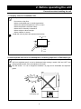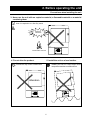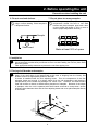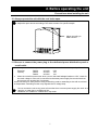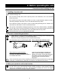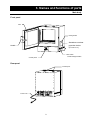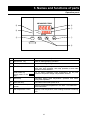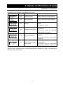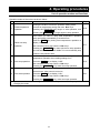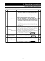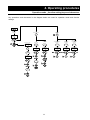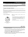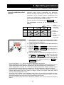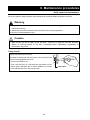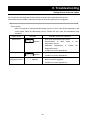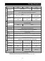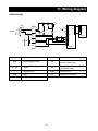
1
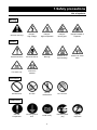
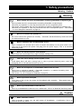
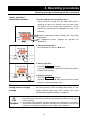
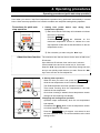
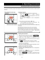
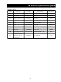
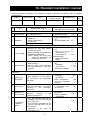
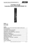
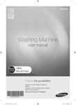
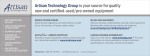
Constant Temperature
Drying Oven
Model DX302/402/602
Fourth edition
● Thank you very much for purchasing this Yamato DX
series constant temperature drying oven.
● Please read the “Operating Instructions” and
“Warranty” before operating this unit to assure proper
operation. After reading these documents, be sure to
store them securely together with the “Warranty” at a
handy place for future reference.
Warning!
Before operating the unit, be sure
to read carefully and fully understand
important
warnings
in
the
operating
instructions.
Yamato Scientific Co., Ltd.
Table of Contents
1. Safety precautions ........................................................................................................................1
Explanation of pictograms................................................................................................................1
List of symbols .................................................................................................................................2
Warning・Cautions ..........................................................................................................................3
2. Before operating the unit ..............................................................................................................4
Precautions when installing the unit .................................................................................................4
3. Names and functions of parts ......................................................................................................9
Main body ........................................................................................................................................9
Operation panel .............................................................................................................................10
Explanation of characters...............................................................................................................11
4. Operating procedures .................................................................................................................12
List of operation modes and functions ...........................................................................................12
Operation mode・function setting keys and characters.................................................................14
Operating procedures (settings for Standalone overheat prevention device (Thermostat)) ...........15
Operating procedures (fixed temperature operation) .....................................................................16
Operating procedures (quick auto stop operation) .........................................................................17
Operating procedures (auto stop operation) ..................................................................................19
Operating procedures (auto start operation) ..................................................................................21
Useful functions (calibration offset function)...................................................................................23
Useful function (setting lock function) ............................................................................................24
Useful function (power outage compensation function)..................................................................25
5. Cautions on handling ..................................................................................................................26
6. Maintenance procedures ............................................................................................................28
Daily inspection/maintenance ........................................................................................................28
7. When the unit is not to be used for a long time or when disposing .......................................29
When the unit is not to be used for a long time or when disposing ................................................29
Notes about disposition..................................................................................................................29
8. Troubleshooting ..........................................................................................................................30
Safety device and error codes .......................................................................................................30
When a malfunction is suspected ..................................................................................................31
9. After sales service and warranty................................................................................................32
When requesting a repair...............................................................................................................32
10. Specifications ............................................................................................................................33
11. Wiring diagram...........................................................................................................................34
12. List of replacement parts ..........................................................................................................35
13. List of dangerous materials......................................................................................................36
14. Standard installation manual....................................................................................................37
1. Safety precautions
Explanation of pictograms
About pictograms
A variety of pictograms are indicated in this operating instruction and on products to
assure safe operation. Possible results from improper operation ignoring them are
classified as follows.
Be sure to fully understand the descriptions below before proceeding to the text.
Warning
Caution
Indicates a situation which may result in death or serious injury
(Note 1)
Indicates a situation which may result in minor injury (Note 2) and
property damage (Note 3).
(Note 1) Serious injury means a wound, an electrical shock, a bone fracture or intoxication
that may leave after effects or require hospitalization or outpatient visits for a long
time.
(Note 2) Minor injury means a wound or an electrical shock that does not require
hospitalization or outpatient visits for a long time.
(Note 3) Property damage means damage to facilities, devices and buildings or other
properties.
Meanings of pictograms
This pictogram indicates a matter that encourages the user to adhere to
warning (“caution” included).
Specific description of warning is indicated near this pictogram.
This pictogram indicates prohibitions
Specific prohibition is indicated near this pictogram.
This pictogram indicates matters that the user must perform.
Specific instruction is indicated near this pictogram.
1
1.Safety precautions
List of symbols
Warning
Danger!:
High voltage
Danger!:
High temperature
Danger!:
Moving part
Danger!:Hazard of
explosion
General cautions
Electrical shock!
Burning!
Caution for no
liquid heating!
Caution for water
leak!
For water only
Poisonous
material
Fire ban
Do not
disassemble
Do not touch
Connect ground
wire
Install levelly
Pull out the power
plug
General warnings
Caution
Prohibitions
General bans
Compulsions
General
compulsions
2
Regular
inspection
1. Safety precautions
Warning・Cautions
Warning
Never operate the unit in an atmosphere containing flammable or explosive gas
Never operate the unit in an atmosphere containing flammable or explosive gas.
Otherwise, an explosion or a fire may result since the unit is not explosion-proof.
See section “Never operate the unit in an atmosphere containing flammable or explosive gas.
Otherwise, an explosion or a fire may result since the unit is not explosion-proof.” See section
“13. List of dangerous materials” on page 36.
Be sure to connect the ground wire.
Be sure to connect the ground wire correctly.
an electrical shock or a fire.
Otherwise, electrical leak may result and cause
Ban on operation when an abnormality occurs
When a smoke or an unusual odor is seen or sensed, immediately turn the power switch on the
main unit off and pull out the power cord (plug) from the power supply. A fire or an electrical
shock may result.
Never use electrical power cords bundled.
When these are used bundled, they might overheat causing a fire.
Take care not to damage electrical power cords.
Avoid tightly bend, pull with a strong force or twist to prevent electrical power cords from
damaging. A fire or an electrical shock may result.
Never use an explosive or a flammable material with this unit.
Never use an explosive material, a flammable material or a material containing them.
explosion or an electrical shock may result.
See section “13. List of dangerous materials” on page 36.
An
Never try to touch a hot part.
Some parts of the unit are hot during and immediately after operation.
possible burning.
Take special care for
Never try to disassemble or alter the unit.
Never try to disassemble or alter the unit. A malfunction, a fire or an electrical shock may result.
Caution
When a thunder is heard.
When a thunder is heard, turn the main power off immediately.
electrical shock may result.
3
A malfunction, fire or an
2. Before operating the unit
Precautions when installing the unit
1. Carefully select an installation site.
Take special care not to install the unit at a place described below:
・On uneven or dirty floor
・Where combustible gas or corrosive gas exists
・Where the ambient temperature is 35°C or more
・Where temperature fluctuates widely
・Where dust or humidity is excessive
・Where subject to direct sunlight
・Where vibration is severe
Install this unit at a place with spaces shown below.
15cm or more
15cm
or
more
15cm
or
more
1m or
more
Front
2. Never operate the unit in an atmosphere containing explosive or flammable gas
Never operate the unit in an atmosphere containing flammable or explosive gas. Since the
unit is not explosion-proof, an arc is discharged when turning a switch “ON” and “OFF” and
during operation and a fire or an explosion may result.
See the section “13. List of dangerous materials” on page 36 for flammable and explosive
gases.
Explosive gas
Combustible gas
4
2. Before operating the unit
Precautions when installing the unit
3. Never use the unit with an explosive material, a flammable material or a material
containing them.
Never use the unit with an explosive material, a flammable material or a material containing
them. An explosion or a fire may result.
Explosive
substance
Combustible material
4. Do not alter the product.
5. Install the unit on a level surface
The user shall never attempt to alter the
unit since it may cause a malfunction.
Flat
Alteration
5
Install the unit on a level surface.
Installing this unit on a slope might cause
unexpected troubles or malfunctions.
2. Before operating the unit
Precautions when installing the unit
6. Do not overload shelves.
7. Do not place too many samples.
Withstand load of each shelf board is
15kg in uniform loading. Place samples in
a dispersed fashion.
Too many samples may prevent proper
temperature control. Be sure to use shelf
boards and place samples apart each other
so as to make free space of 30% or more to
assure proper temperature accuracy.
Sample
15kg
Shelf board
Make at least 30% of space
8. Installation
The unit might fall down or move by an earthquake or an impact resulting a personal injury.
We recommend to make safety measures such as to avoid installing the unit at a place other
than busy places.
Take appropriate safety measures to prevent the unit from tripping over.
9. Placing shelf boards and samples
Two shelf boards are included with this product. One of them has been fixed on the lowest
stage of the shelf pillar of the internal bath at the time of shipping from the factory. Set
another board to an appropriate position in the bath.
A heater is installed under the flow adjusting board. Thus, the temperature of the flow
adjusting board and around it is always higher than the set temperature and placing a
sample directly on the board may damage it or cause a fire. Therefore, the shelf board is
fixed with screws as shown to disable direct placement of samples. Because of the shape
of samples, when the unit is operated with shelf boards removed to accept them, assure
sufficient space between them and the flow adjusting board and never place samples directly
on the board.
Shelf pillar
Shelf clamp
Flow
adjusting
board
Screw
Screw
Shelf board
6
2. Before operating the unit
Precautions when installing the unit
10. Always operate the unit with the vent holes open.
Do not cover the vent holes on the top panel of the unit.
Adjust the open amount according to the water content of a specific sample.
Adjust according to
water content
11. Be sure to connect the power plug to the dedicated power distribution panel or
a wall outlet.
Use a power distribution panel or a wall outlet that meets the electrical capacity of the unit.
Electrical
capacity:
DX302
AC100V
9.5A
DX402
AC100V
14A
DX602
AC100V
14A
* When the unit will not start even when you turn the earth leakage breaker to “ON”, check for
low main voltage or if the unit is connected to the same power supply line as other devices
and connect it to another line if necessary.
Avoid connecting too many devices using a branching outlet or extending a wire with a cord reel
or temperature controlling function may degrade due to voltage drop.
Do not connect the unit to any parts or lines other than a correct power supply line such as a
gas pipe, a water pipe or a telephone line.
Otherwise, an accident or a malfunction may result.
7
2. Before operating the unit
Precautions when installing the unit
12. Handling of a power cord
Never use electrical power cords bundled. When these are used bundled, they might
overheat causing a fire.
Do not convert, forcibly bend, twist or pull the power cord. Otherwise, a fire or an electrical
shock may result.
Do not place the power cord under a desk or a chair, or sand between objects to avoid it
from being damaged. Otherwise, a fire or an electrical shock may result.
Do not place the power cord close to a stove or other heat generating device. Sheath of the
cord may burn and result in a fire or an electrical shock.
If the power cord should be damaged (exposure of core wire or disconnection), immediately
turn the main unit off, pull out the power cord (plug) out of the power supply and ask your
dealer to replace the cord. Otherwise, a fire or an electrical shock may result.
Connect the power cord to an appropriate wall outlet.
13. Be sure to connect the ground wire.
・ When there is no ground terminal available, class D grounding work is necessary and
please consult your dealer or our nearest sales office.
・ Be sure to connect the ground wire to the wall outlet securely.
We recommend use of a ground type outlet When a bipolar type outlet tap is used
tap.
Grounded tap
Power plug
G
Bipolar outlet tap
G
Ground wire
Insert the ground adaptor included as an
option, into a power plug confirming the
polarity of the outlet. Connect the grounding
wire (green) of the ground adaptor to the
ground terminal on the power supply
equipment.
Never connect the ground wire to anything other than the ground terminal such as gas pipe,
water pipe, or telephone line. Otherwise, an accident or a malfunction may result.
When there is no ground terminal.
In this case, class D grounding work is
necessary and please consult your dealer or
our nearest sales office.
14. When you operate the unit for the first time
When you operate the unit for the first time at a higher temperature, the unit may generate
an odor. This is due to decomposed bonding material contained in heat-insulation material
and is not a malfunction of the unit. We recommend operating the unit at the highest
temperature once before starting its regular operation.
8
3. Names and functions of parts
Main body
Front panel
Door
Rating sticker
Standalone overheat
Handle
protection device
(Thermostat)
Main switch
(Earth leakage breaker)
Control panel
Rear panel
Exhaust port
Power cord
9
3. Names and functions of parts
Operation panel
MEASURED TEMP.
⑥
⑤
℃
④
⑦
HEATER
RUN
SET TEMP.
③
RUN
STOP
TIMER
①
SUBMENU
②
No.
Name
Operation/action
①
RUN/STOP key
Used for starting/stoping operation.
②
▼▲ keys
Used for selecting settings.
③
TIMER key
Key for selecting timer operation settings.
Quick auto stop operation, auto stop operation or auto start
operation can be selected.
Key for setting calibration offset temperature, the key lock
SUB MENU key
(Long press of the Timer function or the power outage compensation function.
key)
④
RUN lamp
Illuminates during fixed temperature operation and blinks
during timer operation.
⑤
HEATER lamp
Illuminates while heater power is on.
⑥
Measured
screen
⑦
Set temperature screen
temperature Displays measured temperature in the bath・set characters・
alarm information.
Displays a set temperature, timer settings and timer remaining
time.
10
3. Names and functions of parts
Explanation of characters
Characters on the controller are explained in this section.
Characters
Identifier
Name
Application
AStP
Auto stop setting
Used for setting auto stop operation.
AStr
Auto start setting
Used for setting auto start operation.
Displayed when timer operation has
End
Time up
ended.
See pages 17 and 19.
Used for inputting a calibration offset
cAL
Calibration offset setting
temperature
See section “Using the calibration
offset function” on page 23.
Key locks settings to prevent their
Lock
Key lock of settings
alteration
See section “Using the lock function”
on page 24.
Selects operations after recovery from
Pon
Power outage compen-
power outage.
sation setting
See section “Using the power outage
compensation function” on page 25.
*See the section “Operation mode・function setting keys and characters” on page 14 for characters of
operation modes and functions.
11
4. Operating procedures
List of operation modes and functions
Operation modes of the unit are as shown below:
№
Name
Description
Page
Turning the ELB on to enter the operation setting mode.
1
Fixed temperature
Proceed to temperature setting that uses ▼▲ keys.
operation
Pressing the RUN/STOP key longer to start operation, and
P.16
pressing the RUN/STOP key longer again to stop operation.
Used when you want to “stop fixed temperature operation
being performed automatically in several hours.
Press the TIMER key during fixed temperature operation to
2
Quick auto stop
display “AStP.”
operation
Set a duration before stop with the ▼▲ keys.
P.17
Pressing the RUN/STOP key starts quick auto stop operation
and activates the timer in the middle of it to automatically stop
it after the set period of time.
Used when you want to “set automatic stop for fixed
temperature operation when making settings for it.”
3
Auto stop operation
Press the TIMER key to display “AStP.”
P.19
Set a duration before stop with the ▼▲ keys.
Pressing the RUN/STOP
key starts auto stop operation.
Used when you want to “start operation automatically after
several hours” after power is turned on.
4
Auto start operation
Press the TIMER key to display “AStr.”
P.21
Set a duration before stop with the ▼▲ keys.
Pressing the RUN/STOP
key starts auto start operation.
* Operation mode cannot be changed while the unit is in operation. First stop operation before
changing the mode.
12
4. Operating procedures
List of operation modes and functions
Functions of the unit are as shown below:
Name
№
Description
Page
Automatic overheat prevention function:
This function is linked to the unit set temperature and has
been set to so that it is automatically activated (returned
automatically) at a temperature 12℃ higher than the set
temperature in the bath.
1
Overheat prevention
function
Standalone overheat protection device (Thermostat):
When the temperature in the bath reaches the set
P.15
temperature of the standalone overheat protection device
(Thermostat), its heater circuit trips to shut off controller
operation.
The temperature can be set with the manual dial on the
hydraulic overheat prevention device installed at the right
side of the unit.
Calibration offset function compensates any differences
between the target temperature in the bath and the control
2
Calibration
temperature of the controller (sensor temperature.)
Offset function The function can compensate to either plus or minus side
P.23
for the whole temperature band of the unit.
This compensation can be set with the SUB MENU keys.
3
Setting lock function
This function locks the set operation status.
The lock can be set or released with the SUB MENU key.
P.24
This function returns the main unit operation to the resume
4
Power outage
status after recovery from power outage, or keeps the
compensation function
current stop status.
This compensation can be set with the SUB MENU keys.
13
P.25
4. Operating procedures
Operation mode・function setting keys and characters
Key operations and characters in the diagram below are used for operation mode and function
settings.
ELB ON
Fixed temp.
operation
Function
setting
Timer operation
Long
press
TIMER
SUB
MENU
Temperature
setting
Setting lock
function
Power outage
compensation
function
AStr
cAL
LocK
Pon
Time setting
Compensation
setting
Lock setting
Power outage
compensation
setting
Auto stop
Auto start
Fixed temp.
operation
AStP
TIMER
Time setting
▲
Time setting
One
sec.
▲
RUN/
STOP
▲
AStP
One
sec.
Auto start of
operation
▲
▲
RUN/
STOP
Timer start
RUN/
STOP
Timer start
Timer start
One
sec.
End
One
sec.
One
sec.
RUN/
STOP
RUN/
STOP
Operation
stop
Automatic
stop of
operation
End
One
sec.
▲
RUN/
STOP
Operation
stop
14
Minus
Long
press
▲
Operation
start
Calibration offset
function
Quick auto stop
▲
SUB
MENU
Plus off
Long
press
▲
RUN/
STOP
▲
SUB
MENU
on off
Long
press
▲
▲
Long
press
▲
▲
SUB
MENU
on
4. Operating procedures
Operating procedures (settings for Standalone overheat prevention device
(Thermostat))
As a safety measure for preventing overheat, a standalone overheat prevention device (Thermostat)
hydraulic overheat prevention device (manual return) is installed.
Temperature setting range and functions
The temperature setting range for the standalone overheat prevention device (Thermostat) is “50 ~
350 .”
When the temperature in the bath keeps rising beyond the controller set temperature and reaches the
set temperature of the standalone overheat prevention device (Thermostat), the heater circuit trips
and the controller operation is shut off.
When the standalone overheat prevention device (Thermostat) is activated, it will not be released until
the ELB is turned on.
How to set temperature
Setting
the
standalone
overheat
prevention
device
(Thermostat)
・ Set the temperature scale on the standalone overheat
prevention device (Thermostat) installed on the right side
of the unit to the arrow in the diagram shown left.
・ Turn the ELB to “OFF” and wait for a while without
opening the door.
・After a while, turn the ELB “ON.” (Turn the ELB “ON”.)
Set the temperature scale
to the arrow
Caution
①
Set temperature as “set temperature +20℃” as a rough standard and add 5℃ to the setting
if the device functions improperly.
②
The temperature setting range for the standalone overheat prevention device is “50℃~
320℃.” Be sure to set the overheat prevention activation temperature correctly otherwise the
device may not start, the overheat prevention device is activated before temperature in the
bath increases completely, or a fire or other unexpected accidents may result.
The temperature is set at 320℃ on shipping from the factory.
③ The standalone overheat prevention device (Thermostat) has been designed to prevent
overheating of devices not to protect samples. The device does not prevent accidents
caused from use of explosive or flammable materials.
15
4. Operating procedures
Operating procedures (fixed temperature operation)
How to start fixed
temperature operation
1.Turn the ELB ON. (Turn the ELB to “ON.”)
When the ELB is turned ON, the intial values will be
displayed for about four seconds, then the initial screen
will appear and the current bath temperature and the
previous set temperature are displayed on each of the
indicators.
MEASURED TEMP.
℃
HEATER
Measured temperature screen: Displays the current bath
temperature
Set temperature screen: Displays the previous set
temperature
RUN
設定温度
2. Setting the temperature
Set a temperature using the ▼▲ keys.
MEASURED TEMP.
℃
HEATER
RUN
SET TEMP.
RUN
TIMER
STOP
SUB MENU
3. Starting operation
Press the RUN/STOP key longer.
MEASURED TEMP.
℃
Fixed value operation will start and the RUN lamp and the
HEATER lamp come on.
HEATER
RUN
SET TEMP.
TIMER
RUN
STOP
SUB MENU
4. Stopping operation
Press the RUN/STOP key longer.
Operation stops, the RUN lamp goes off and the screen
switches to the initial setting screen.
When you want to correct
setting errors or change
settings
When you want to change settings, press the ▼▲ keys on
the current screen to enter the setting mode where you can
change settings. Blink stops three seconds after three
seconds after change and setting is completed.
Caution
① When you want to lower the set temperature during fixed temperature operation,
note that it takes some time to reach the reset temperature since the unit has no
cooling capacity.
② Immediately after operation has been stopped, the temperature in the bath is
around the set temperature. Operation stop refers only to machine stop and time
needed for decreasing the emperature in the bath is not considered.
16
4. Operating procedures
Operating procedures (quick auto stop operation)
Used when you want to “stop fixed temperature operation being performed automatically in several
hours. Quick auto stop operation is a function to enable auto stop timer setting during operation.
Procedures for quick auto
stop operation
1. Setting
time
period
before
stop
during
fixed
temperature operation
① Make sure that the RUN lamp is illuminated to indicate
the unit is in operation.
MEASURED TEMP.
℃
HEATER
RUN
SET TEMP.
RUN
TIMER
STOP
SUB MENU
②
①
Press the TIMER key.
Characters AStP
are indicated on the
measured temperature screen to indicate the auto
stop operation mode and set duration blinks on the set
temperature screen.
② Set a duration you want using the ▼▲ keys.
About the timer function The maximum time that can be set for the timer is 999 hours
50 minutes.
Up to 99 hours 59 minutes, time can be set in minutes.
One hundred hours and over are set only in 10 minutes.
Keep the ▼▲ keys pressed to continuously change set time
and you can quickly reach the time you want. Press the ▼▲
keys once at a time for fine adjustment.
2. Starting timer operation
When the time you want is set, press the RUN/STOP key
MEASURED TEMP.
℃
while the set temperature screen is blinking.
The RUN lamp blinks and timer operation is started.
HEATER
RUN
SET TEMP.
RUN
TIMER
STOP
SUB MENU
Timer starts counting when the temperature in the bath
reaches the set temperature.
Once timer counting is started, the set temperature screen
changes to the remaining time display.
3.Stopping and ending timer operation
Operation stops automatically when the set temperature
MEASURED TEMP.
℃
HEATER
RUN
SET TEMP.
TIMER
SUB MENU
RUN
STOP
has elapsed.
Characters End
blink on the set temperature screen
to indicate operation has ended.
Press the RUN/STOP key for approx. one second to end
the timer operation mode. The screen switches to the initial
setting screen.
17
4. Operating procedures
Operating procedures (quick auto stop operation)
When you want to correct set When you want to change settings, press the ▼▲ keys on
the current screen to enter the setting mode where you can
temperature or set time, or
change settings. Blinking stops three seconds after three
change settings
seconds after change and setting is completed.
Note,
however, that temperature changes after timer activation are
counted also while temperature is changing.
When you want to change settings before timer activation,
press the TIMER key on the current screen to enter the
setting mode where you can change settings. Enter a time
duration from when the set temperature is reached to the
time the device shall be stopped.
When you want to change settings after timer activation,
press the TIMER key on the current screen to enter the
setting mode where you can change settings. Note, however,
you need to set a time calculated by adding the time already
passed to the time to be added.
After change has been made, press the RUN/STOP
key to
complete the process.
When you want to stop quick auto stop operation in the
middle of it, press the RUN/STOP key long once to stop
device control once, then make settings again in the
appropriate mode.
In terms of the remaining time display
a blinking
dot indicates count down and an illuminating dot indicates a
wait status (while temperature is increasing or decreasing to
the set temperature) during which the timer has stopped
counting.
18
4. Operating procedures
Operating procedures (auto stop operation)
This mode automatically stops fixed temperature operation after a certain time from its start set with
the timer.
Procedures for auto stop
operation
MEASURED TEMP.
℃
1. Setting a stop time
① After confirming the temperature you want is set,
Press the TIMER key to display characters
AStP
on the measured temperature screen that
indicate auto stop operation.
The set time is displayed on the set temperature
HEATER
RUN
SET TEMP.
RUN
TIMER
screen.
STOP
SUB MENU
② Set a time you want using the ▼▲ keys.
②
①
Pressing the▼▲ keys makes the set time blink. The
time is determined when blinking stops.
About the timer function The maximum time that can be set for the timer is 999 hours
50 minutes.
Up to 99 hours 59 minutes, time can be set in minutes.
One hundred hours and over are set only in 10 minutes.
Keep the ▼▲ keys pressed to continuously change set time
and you can quickly reach the time you want. Press the ▼
▲ keys once at a time for fine adjustment.
2. Starting timer operation
When the time you want is set, press the RUN/STOP key
MEASURED TEMP.
℃
HEATER
RUN
SET TEMP.
RUN
TIMER
STOP
SUB MENU
for about one second while characters AStP
that
indicate auto stop operation are displayed on the
measured temperature screen and the set time on the set
temperature screen.
The RUN lamp blinks and timer operation is started.
Timer starts counting when the temperature in the bath
reaches the set temperature.
Once timer counting is started, the set temperature screen
changes to the remaining time display.
3. Stopping and ending timer operation
Operation stops automatically when the set temperature
MEASURED TEMP.
℃
HEATER
RUN
SET TEMP.
TIMER
SUB MENU
RUN
STOP
has elapsed.
Characters End
blink on the set temperature
screen to indicate operation has ended.
Press the RUN/STOP key for approx. one second to end
the timer operation mode. The screen switches to the initial
setting screen.
19
4. Operating procedures
Operating procedures (auto stop operation)
When you want to correct set When you want to change settings, press the ▼▲ keys on
the current screen to enter the setting mode where you can
temperature or set time, or
change settings. Blinking stops three seconds after three
change settings
seconds after change and setting is completed. Note,
however, that temperature changes after timer activation are
counted also while temperature is changing.
When you want to change settings before timer activation,
press the TIMER key on the current screen to enter the
setting mode where you can change settings. Enter a time
duration from when the set temperature is reached to the
time the device shall be stopped.
When you want to change settings after timer activation,
press the TIMER key on the current screen to enter the
setting mode where you can change settings. Note, however,
you need to set a time calculated by adding the time already
passed to the time to be added.
After change has been made, press the RUN/STOP key to
complete the process.
Auto stop operation is not available together with auto start
operation.
When you want to stop auto stop operation in the middle of
it, press the RUN/STOP key long once to stop device control
once, then make settings again in the appropriate mode.
In terms of the remaining time display
a blinking
dot indicates count down and an illuminating dot indicates a
wait status (while temperature is increasing or decreasing to
the set temperature) during which the timer has stopped
counting.
20
4. Operating procedures
Operating procedures (auto start operation)
This mode automatically starts fixed value operation after a certain time from its start set with the
timer.
However, operation does not stop automatically but needs to be stopped manually.
Procedures for auto start
operation
MEASURED TEMP.
℃
HEATER
1. Setting an operation start time
① After confirming the temperature you want is set,
Press the TIMER key to display characters
AStr
on the measured temperature screen that
indicate auto start operation.
The set time is displayed blinking on the set
temperature screen.
RUN
SET TEMP.
RUN
TIMER
STOP
SUB MENU
②
①
② Set a time you want using the ▼▲ keys.
Pressing the ▼ ▲ keys makes the set time blink.
The time is determined when blinking stops.
About the timer function The maximum time that can be set for the timer is 999 hours
50 minutes.
Up to 99 hours 59 minutes, time can be set in minutes.
One hundred hours and over are set only in 10 minutes.
Keep the ▼▲ keys pressed to continuously change set time
and you can quickly reach the time you want. Press the ▼▲
keys once at a time for fine adjustment.
MEASURED TEMP.
℃
HEATER
RUN
SET TEMP.
RUN
TIMER
STOP
SUB MENU
MEASURED TEMP.
℃
HEATER
RUN
SET TEMP.
TIMER
RUN
2. Starting timer operation
When the time you want is set, press the RUN/STOP key
for about one second while characters AStr
that
indicate auto start operation are displayed on the
measured temperature screen and the set time on the set
temperature screen.
Timer starts counting when the RUN/STOP key is pressed
and RUN lamp blinks.
Display on the measured temperature screen switches
from set time display to remaining time display.
3.Stopping and ending timer operation
Operation automatically starts at the set time and the RUN
lamp comes on.
To stop operation, press the RUN/STOP key for approx.
one second to end the timer operation mode. The screen
switches to the initial setting screen.
STOP
SUB MENU
21
4. Operating procedures
Operating procedures (auto start operation)
When you want to
correct set temperature or set time, or
change settings
When you want to change the set temperature during timer counting,
press the ▼▲ keys during that status to switch the set temperature
screen to the set temperature input mode, which blinks to enable
change of the set temperature with the ▼▲ keys.
When you want to change the set time during timer counting, press
the TIMER key during that status to switch the set temperature
screen to the set time input mode, which blinks to enable change of
the set time with the ▼▲ keys.
In either case, the set temperature screen will stop blinking after a
while and switche to the timer count mode and the change made is
determined. Note, however, when you change the set time you need
to set a time calculated by adding the time already passed to the time
to be added.
When operation has started after the auto start time, you cannot
change the set time.
When you want to stop auto start operation in the middle of it, press
the RUN/STOP key long to stop device control once, then make
settings again in the appropriate mode.
In terms of the remaining time display
a blinking dot
indicates count down and an illuminating dot indicates a wait status
(while temperature is increasing or decreasing to the set
temperature) during which the timer has stopped counting.
22
4. Operating procedures
Useful functions (calibration offset function)
Using the calibration offset
function
Calibration offset function compensates any differences
between the target temperature in the bath and the control
temperature of the controller (sensor temperature.) The
function can compensate in parallel to either plus or minus
side for the whole temperature band of the unit.
The lock can be set or released with the SUB MENU keys.
The temperature is set at “0” on shipping from the
factory.
Control
temperature after
minus side
compensation
Current
temperature
Control
temperature after
plus side
compensation
MEASURED TEMP.
℃
HEATER
RUN
SET TEMP.
RUN
TIMER
SUB MENU
③
STOP
④
① Start operation at the target set temperature and confirm
the temperature in the bath with a temperature recorder
after temperature has stabilized.
② Confirm the difference between the set temperature and
that in the bath.
③ Press the TIMER key (SUB MENU key) long to enter the
sub menu mode.
Press the TIMER key (SUB MENU key) several times to
select the characters cAL
that indicates the
calibration offset function.
④ Enter the difference between the set temperature and the
temperature in the bath using the ▼▲ keys and press
the TIMER key (SUB MENU key) long to exit the sub
menu mode. (When you want to set the key lock
function, proceed to character selection process for the
key lock function without pressing the TIMER key
(SUB MENU key) long.)
* You can set either of + or – side for the offset compensation temperature.
When compensation is set for the – side, the measured temperature display decreases by the
compensation temperature while the temperature in the bath increases by the same amount.
When compensation is set for the + side, the measured temperature display increases by the
compensation temperature while the temperature in the bath decreases by the same amount.
* Since too large a compensation value may result in larger difference between the actual and
indicated temperatures and may present a danger, consult our nearest sales office before
entering a large compensation value.
* The device has, in addition to the calibration offset function, the two-point compensation function
that adjusts offset for the lower temperature range and higher temperature range, for which
adjustment temperatures have been input on shipping from the factory.
* Consult the nearest sales office before attempting validation work for the temperature adjusting
device.
23
4. Operating procedures
Useful function (setting lock function)
Using the lock function
This function locks the set operation status.
The temperature is set at “off” on shipping from the
factory.
① Press the TIMER key (SUB MENU key) long to enter
the sub menu mode.
MEASURED TEMP.
℃
HEATER
RUN
SET TEMP.
RUN
TIMER
Press the TIMER key (SUB MENU key) several times
to select the characters Lock
setting lock function.
that indicate the
STOP
SUB MENU
③ “Off” is displayed on the set temperature screen. To
lock settings, change to “on” using the ▲ key.
MEASURED TEMP.
℃
Press the TIMER key (SUB MENU key) long to exit
the sub menu mode.
HEATER
RUN
SET TEMP.
RUN
TIMER
STOP
SUB MENU
(3) To release lock, press the TIMER key (SUB MENU
MEASURED TEMP.
℃
Lock is released when “off” is selected using the ▼
HEATER
RUN
SET TEMP.
TIMER
SUB MENU
key) long again and select the characters Lock
that indicate setting lock using the ▼▲ keys.
RUN
key.
STOP
* When the lock function is “on”, keys other than the
RUN/STOP key and the TIMER key (SUB MENU
key) are locked.
24
4. Operating procedures
Useful function (power outage compensation function)
Using the power outage
compensation function
The power outage compensation function returns the main
unit operation to the resume status after recovery from power
outage, or keeps the current stop status.
The function is set at “on” on shipping from the factory.
① Press the TIMER key (SUB MENU key) long to enter
the sub menu mode.
MEASURED TEMP.
℃
HEATER
RUN
SET TEMP.
RUN
TIMER
Press the TIMER key (SUB MENU key) several times
to select the characters Pon
that indicate the
power outage compensation function.
STOP
SUB MENU
② “On” is displayed on the set temperature screen. The
device keeps stop status after recovery from power
MEASURED TEMP.
℃
RUN
SET TEMP.
TIMER
outage when this setting is set to “off” using the ▼
key.
HEATER
RUN
STOP
Press the TIMER key (SUB MENU key) long to exit
the sub menu mode.
SUB MENU
25
5. Cautions on handling
Warning
1. About handling of flammable or combustible solution
The unit is not explosion proof. Take special care for handling samples on which explosive
substances, combustible substances or substances containing them. Flammable or
combustible solution will evaporate when left at a room temperature (or at a lower
temperature for some types of solutions) and may be ignited and explode from switches,
lights and other ignitable sources. Be sure to assure sufficient ventilation when using these
materials.
See section “13. List of dangerous materials” on page 36.
2. Ban on use/countermeasures when an error occurs
If smoke is emerges on the unit or an odd odor is felt, immediately turn the ELB on the main
unit off, turn the power supply off and contact your dealer or a Yamato sales office for
inspection. Otherwise, a fire or an electrical shock may result. The user shall never attempt
to repair the unit to avoid any possible dangers.
Caution
1. Do not step on the unit.
Do not step on the unit. Otherwise, the unit may trip over or be damaged resulting a personal
injury or a malfunction.
2. Do not put or drop an object on the unit.
2.Do not put or drop an object on the unit. Since the unit contains high precision devices,
vibrations or shock may cause a malfunction.
3. When a thunder is heard.
When a thunder is heard, turn the ELB on the main unit off then turn the main power off
immediately. Otherwise, a lightning strike may result and cause a fire.
4. During night and not to be operated for a long period of time.
During the night and when you want to stop the unit for a longer period of time, turn the ELB
to “off” and pull out the power cord from the power supply.
5. Do not operate the unit with the door open.
・When the unit is operated with the door open, the heater may overheat pausing a possible
danger. Be sure to operate the unit with the door closed.
・After operation has been completed, do not leave the unit with its door open in order to, for
example, cool down samples earlier. Heat from inside the bath may cause deformation of
the control panel of a malfunction of the control devices.
26
5. Cautions on handling
Caution
6. Prohibition of use of corrosive samples
Although SUS304 stainless steel is used for components in the bath, note that they might
corrode with strong acid. Door packing is made of silicon rubber. Note that silicon rubber
packing may corrode with acid, alkali, oil or halogen-based solvent.
7. Always operate the unit at a correct ambient temperature.
Operational temperature range for the model DX302/402 is room temperature +5℃~
300℃;DX602 room temperature +5℃~280℃.
Never try to operate the unit outside the operating temperature range.
8. About placement of samples
Withstand load of the shelf boards included is approx. 15kg. Do not place a sample heavier
than this withstand load.
When putting samples, arrange them as dispersed as possible.
Too many samples may prevent proper temperature control. To assure proper temperature
precision, put samples with a space at least 30% of the shelf board area.
9. Do not put a sample on the bottom inside the product.
Never place a sample on the bottom, since if the unit is operated with a sample directly
placed on the bottom of the internal bath, the optimal performance of the unit will not be
attained, and temperature in the product may increase excessively causing a malfunction.
Arrange samples on the shelf boards supplied and set the board on the shelf clamps.
10. About recovery from power outage.
When the power is applied again after the unit has stopped due to power outage, the unit
will automatically return to the status immediately before the power outage and resumes
operation.
Turn the ELB off if you do not want to resume operation by automatic recovery.
11. About two-tier stacking
Stack the units in two tiers using the special stacking clamps included as optional
accessories.
Do not stack the units directly on each other in two tiers.
27
6. Maintenance procedures
Daily inspection/maintenance
Be sure to perform daily inspection and maintenance to assure reliable operation of the unit.
Warning
● Be sure to pull out the power cord unless necessary before trying to do inspection and
maintenance works.
● Start these works after the device has returned to the normal temperature.
● Never try to disassemble the unit.
Caution
● Wipe off any dirt with a tightly wrung soft cloth.
Never try to clean the unit with benzene,
thinner or scouring powder, or rub with a scrubbing brush. Deformation, degradation or
discoloration may result.
Every month
Inspect the functions of the ELB.
Test shall be performed with the power cord connected and
power is being supplied to the unit.
・First turn the ELB to “off.”
・Then, turn the ELB “on” and press the test button on the
device with a ball-point pen to check whether it is turned
off to indicate that it is in the normal state.
28
Test button
7. When the unit is not to be used for a long time
or when disposing
When the unit is not to be used for a long time or when disposing
Caution
Warning
When the unit is not going to be used for a long
When disposing the unit
time
● Do not leave the unit in the area where
● Turn the ELB to off and pull out the power
children may have access.
● Be sure to remove handles before disposing
cord.
the unit to prevent the doors from locking.
● In general, dispose the unit as a bulky waste.
Notes about disposition
Always pay attention to the preservation of the global environment.
・ We highly recommend taking the unit apart as far as possible for separation or recycling to
contribute to the preservation of the global environment. Major components and materials for the
unit are as follows:
Names of major
Major materials
components
Major mechanism part components
Enclosure
Steel plate Melamine resin baking finish
Internal bath
Stainless steel SUS304
Heat insulator
Rock wool
Door packing
Silicon rubber foam
Nameplates
Polyethylene (PET) resin film
Major electric parts
Heater
Iron-chrome heater
Boards
Glass fiber and other composite parts
Power cord, wire material
and others
Synthetic rubber sheathed and resin sheathed wires
29
8. Troubleshooting
Safety device and error codes
The unit has the self diagnostic function with a controller and a separate safety device.
Table below shows possible causes and measures when the safety device is triggered.
[Error codes]
When a functional or mechanical abnormality occurs, an error code will be displayed on the
control panel. When an abnormality occurs, confirm the error code and immediately stop
operation.
Safety device
Symptom
Sensor error
appears
Possible causes and measures
z
Error in the temperature input circuit
z
Disconnection
or
other
errors
in
the
outside
the
temperature sensor.
z
Measured
temperature
is
displayable range
Contact our service department.
Memory error
z
appears
Measured
temperature error
----
Memory setting error
Contact our service department.
z
---- appears
When the upper limit alarm of the temperature
alarm function is triggered.
Contact our service department.
30
8. Troubleshooting
When a malfunction is suspected
If any of the symptoms below occurs
Symptom
Turning the ELB to on will
not activate the unit.
Temperature does not rise.
Check
● If the power cord is connected to the power supply securely.
● If power outage is not occurring.
● If the standalone overheat prevention device is working.
● If the set temperature is below that in the device.
● If the power supply voltage has declined.
● If the ambient temperature is not low.
● If cooling load for inside the bath is not too large.
Temperature fluctuates
during operation.
● If the set temperature is appropriate.
● If the power supply voltage has declined.
● If ambient temperature fluctuates widely.
● If cooling load for inside the bath is not too large.
Displayed temperature
differs from the
measurement.
● If the calibration offset setting is not other than “0”. Set it to “0.”
Confirm settings in “Useful functions (calibration offset function)”
in page 23.
If power outage occurs
When the power is applied again after the unit has stopped due to power outage, the unit will
automatically return to the status immediately before the power outage and resumes operation.
Turn the ELB off if you do not want to resume operation by automatic recovery.
◆If the symptom does not match any of the above, immediately turn the ELB on the main unit off,
pull out the power cord from the power supply and contact your dealer or one of our sales
offices.
31
9. After sales service and warranty
When requesting a repair
When requesting a repair
If any trouble occurs, immediately stop operation, turn the ELB off, pull out the power plug and
contact your dealer or our sales office.
Information necessary for requesting a repair
◆Model name of the product
◆Serial number
◆Date (y/m/d) of purchase
Confirm on the warranty card or the nameplate installed on
the unit.
See the section”3. Names and functions of parts” in page 9
◆Description of trouble (as in detail as possible)
Be sure to indicate the warranty card to our service representative.
Warranty card (attached separately)
z
Warranty card is given by your dealer or one of our sales offices and please fill in your dealer,
date of purchase and other information and store securely.
z
Warranty period is one full year from the date of purchase. Repair service for free is available
according to the conditions written on the warranty card.
z
For repairs after the warranty period consult your dealer or one of our sales offices. Paid
repair service is available on your request when the product’s functionality can be maintained
by repair.
Minimum holding period of repair parts
The minimum holding period of repair parts for this product is seven years after end of
production.
Repair parts here refer to parts necessary for maintaining performance of the product.
32
10. Specifications
DX302
Model
Performance
Mechanism
Control assembly
Safety device
Standard
Exhaust port
40℃~280℃
At no load and at an ambient temperature of 23℃
Temperature
control precision
Temperature rise
time
DX602
40℃~300℃
Temperature
control range
Temperature
distribution
precision
DX402
±1℃(setting: 300℃, exhaust port fully opened)
±10℃
±10℃
(setting: 280, exhaust port
(setting: 300, exhaust port fully opened)
fully opened)
Approx. 45 minutes
Approx. 60 minutes
Approx. 80 minutes
(Room temperature~
(Room temperature~
(Room temperature~
300℃)
300℃)
280℃)
Rotation damper with opening rate of 20% when closed
Iron-chrome heater
Heater
0.9 kW
1.36 kW
Control system
PID control of heater output with a micro computer
Setting system
Digital setting using up/down keys
Operation mode
Fixed temperature operation, quick auto stop operation
Auto stop operation, auto start operation
Sensor
Auxiliary
functions
Controller
Self diagnostic
function
Protection device
Outer dimensions
(mm)
(w x d x h)
Inner dimensions
(mm)
(w x d x h)
Internal volume
Weight
Power supply
(i50/60Hz)
K thermocouple
Lock function, power outage compensation function, calibration offset function
Temperature sensor error, memory error, auto overheat prevention,
measured temperature error
ELB with an over current protector,
Standalone overheat prevention device (Thermostat)
400×440×630
550×540×730
700×640×830
300×310×300
450×410×400
600×510×500
28ℓ
74ℓ
153ℓ
Approx. 23kg
Approx. 38kg
Approx. 56kg
100V 9.5A
100V 14A
100V 14A
Shelf board x 2 (withstand load approx. 15kg /each), operating
instructions, warranty card
*Performance values are for the VAC100 power supply.
Included items
*Operating environmental temperature range for this device is 5℃~35℃.
33
11. Wiring diagram
DX302/402/602
X2-1
T
ELB
X2-2
OH
1
AC100V
TH
X1
-
X2
X1
2
H2
1
3
ELB
H1, H2
T
Symbol
Earth leakage breaker
OH
Heater
TH
Terminal block
SSR
X1, X2
Relay
22
22
PIO
6
7
CONT
Part name
SSR
CN1
8
9
4
Symbol
SSR
3
4
1
CN1
3
4
5 TB1
2
H1
1
1
+2
CONT
PIO
34
Part name
Standalone overheat prevention
device (Thermostat)
Temperature sensor
(K-thermocouple)
Planar board
Display circuit board
12. List of replacement parts
Common parts
Symbol
TH1
CONT
PIO
-
Part name
Temperature sensor
Code No.
1-16-003-0049
Specifications
Manufacturer
LCK-M1-2000Y K single
Yamato
Planar board
LT00007640
CN40B-Y
Yamato
Display circuit board
LT00007639
CN40B-Y
Yamato
50 ㎜
Yamato
Tough card
1-13-000-0009
X1
Relay
LT00032865
X2
Relay
2-05-008-0002
AP3124K
Matsushita
SSR
SSR
2-16-000-0035
TRS5255
Toho
LT00008924
2.0sq 3P
Yamato
ELB
Power cord
Earth leakage breaker
2-06-000-0019
FC-0T 1b 100V
FG32R/15-30MA 15A
Fuji
Fuji
Standalone overheat
OH
prevention device
LT00033261
(Thermostat)
35
55.13265.900
E.G.O
13. List of dangerous materials
Never use an explosive substance a flammable substance or a substance containing
Explosive
substance
Explosive
substances
Explosive
substance
them for this device.
① Nitroglycol, glycerine trinitrate, cellulose nitrate and other explosive nitrate esters
② Trinitrobenzen, trinitrotoluenem, picric acid and other explosive nitro compounds
③ Acetyl hydroperoxide, methyl ethyl ketone peroxide, benzoyl peroxide and other
organic peroxides
Metal “lithium”, metal “potassium”, metal “natrium”, yellow phosphorus, phosphorus
sulfide, red phosphorus, celluloids, calcium carbide (a.k.a, carbide), lime phosphide,
magnesium powder, aluminum powder, metal powder other than magnesium and
aluminum powder, sodium dithionous acid (a.k.a., hydrosulphite)
Oxidizing substances
② Potassium perchlorate, sodium perchlorate, ammonium perchlorate, and other
perchlorates
③ Potassium perchlorate, sodium perchlorate, ammonium perchlorate, and other
inorganic perchlorates
④ Potassium nitrate, sodium nitrate, ammonium nitrate, and other nitrates
⑤ Sodium chlorite and other chlorites
Flammable substances
⑥ Calcium hypochlorite and other hypochlorites
Combustible
gas
Flammable substances
① Potassium chlorate, sodium chlorate, ammonium chlorate, and other chlorates
① Ethyl ether, gasoline, acetaldehyde, propylene chloride, carbon disulfide, and other
substances with ignition point at a degree 30 or more degrees below zero.
② n-hexane, ethylene oxide, acetone, benzene, methyl ethyl ketone and other
substances with ignition point between 30 degrees below zero and less than zero.
③ Methanol, ethanol, xylene, pentyl acetate, (a.k.a.amyl acetate) and other substances
with ignition point between zero and less than 30 degrees.
④ Kerosene, light oil, terebinth oil, isopenthyl alcohol (a.k.a. isoamyl alcohol), acetic
acid and other substances with ignition point between 30 degrees and less than 65
degrees.
Hydrogen, acetylene, ethylene, methane, ethane, propane, butane and other
Substance which is a flammable gas at 15 degrees, one air pressure.
(Quoted from the separate table 1 in Article 6, the enforcement order of the Industrial
Safety and Health Law)
36
14. Standard installation manual
* Install the product according to the following: (Confirm separately for optional items or special
specifications)
Model
№
Serial number
Item
Installation mgr.
(company name)
Date
Implementation method
Installation mgr.
TOC No. Reference page of the
operating instruction manual
Specifications
Check for number of staffs against
10. Specifications field
the included item field
・ Visual check of environmental 2. Before operating the
conditions
unit
2 Installation
Caution: Take care for
・On the installation site
environment
・Securing a space
Operation-related matters
2. Before operating the
・ Measure the user side voltage
unit
(outlet) with a tester
・ Be sure to connect
・ Measure voltage during operation
the ground wire.
1 Source voltage
(shall meet the standard)
・ Power supply is ….
Caution: Always use a plug that 10.Specifications
meets the specification for
・ Specification-power
attaching to the ELB.
supply
2. Before operating the
unit
・ Starts operation
・ Installation
Performs fixed value operation,
2 Operation start
auto stop operation or auto start
procedures…
operation
4. Operating procedures
1
Included items
P.33
P.4
P.8
P.7
P.33
P.4~
8
P.12~
25
Description
Operational
descriptions
Explain operations of each component according to the operational
instructions
2
Error codes
Explain the customer about error
codes and procedures for release
according
to
the
operational
instructions
3
Maintenance
and inspection
4
Completion of
installation
Entries
1
4. Operating procedures P.12~
・ Operating
25
procedures
P.1~
1. Safety precautions ~
~36
13.List of dangerous
materials
8. Troubleshooting
P.30
32
~ 9. After sales service
and warranty
6. Maintenance
procedures
P.28
・ Daily inspection/
maintenance
・ Fill in the installation date and the 9. After sales service and warranty
installation mgr. on the nameplate
P.32
of the main unit
Explain
operations
of
each
component
according
to
the
operational instructions
・ Fill in necessary information to the
warranty card and hand it over to
the customer
・ Explanation of the route for
after-sales service
37
Judg
ment
Judg
ment
Limited liability
Be sure to use the unit strictly following the handling and operating instructions in
this operating instruction.
Yamato Scientific Co., Ltd. assumes no responsibility for an accident or a malfunction
caused by use of this product in any way not specified in this operating instruction.
Never attempt to perform matters prohibited in this operation instruction.
Otherwise, an unexpected accident may result.
Notice
●Descriptions in this operating instruction are subject to change without notice.
●We will replace a manual with a missing page or paging disorder.
Operating instruction
Constant Temperature Drying Oven
DX302/402/602
Fourth edition Dec 10 2009
Yamato Scientific Co., Ltd.
〒103-8432
2-1-6, Nihonbashi, Honcho, Chuo-ku,
Tokyo
Customer support center
Tool free: 0120-405525
http://www.yamato-net.co.jp
38