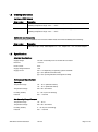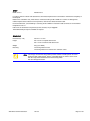
1
Hurricane-LX800
EPIC Single Board Computer
Technical Manual
TME-EPIC-HURLX-R3V5.docx
Revision 3.5 / April 11
© LiPPERT Embedded Computers GmbH
Hans-Thoma-Str. 11
D-68163 Mannheim
http://www.lippertembedded.com/
Technical Manual Hurricane-LX800
LiPPERT Document: TME-EPIC-HURLX-R3V5 Revision 3.5
Copyright ©2011 LiPPERT Embedded Computers GmbH, All rights reserved
Trademarks
MS-DOS, Windows, Windows 95, Windows 98, Windows NT and Windows XP are trademarks of Microsoft
Corporation. PS/2 is a trademark of International Business Machines, Inc. Intel and Solid State Drive are
trademarks of Intel Corporation. Geode is a trademark of Advanced Micro Devices. PC/104 is a registered
trademark of PC/104 Consortium. All other trademarks appearing in this document are the property of their
respective owners.
Disclaimer
Contents and specifications within this technical manual are subject of change without notice.
LiPPERT Embedded Computers GmbH provides no warranty with regard to this technical manual or any other
information contained herein and hereby expressly disclaims any implied warranties of merchantability or fitness
for any particular purpose with regard to any of the foregoing. LiPPERT Embedded Computers GmbH assumes no
liability for any damages incurred directly or indirectly from any technical or typographical errors or omissions
contained herein or for discrepancies between the product and the technical manual. In no event shall LiPPERT
Embedded Computers GmbH be liable for any incidental, consequential, special, or exemplary damages, whether
based on tort, contract or otherwise, arising out of or in connection with this user’s guide or any other information
contained herein or the use thereof.
TME-EPIC-HURLX-R3V5.docx
Rev 3.5
Table of Contents
1
1.1
Overview
1
Introduction ........................................................................................................................ 1
Features ....................................................................................................................................1
Block Diagram ...........................................................................................................................3
1.2
Ordering Information ........................................................................................................... 4
Hurricane-LX800 Models ..........................................................................................................4
Cable Sets and Accessories .....................................................................................................4
1.3
Specifications ..................................................................................................................... 4
Electrical Specifications ............................................................................................................4
Environmental Specifications....................................................................................................4
MTBF .........................................................................................................................................5
Mechanical ................................................................................................................................5
2
2.1
Getting Started
6
Connector Locations .......................................................................................................... 6
Top ............................................................................................................................................6
Bottom ......................................................................................................................................7
2.2
3
Hardware Setup .................................................................................................................. 8
Module Description
9
3.1
Processor ........................................................................................................................... 9
3.2
I/O Companion ................................................................................................................. 10
3.3
Graphics-Controller .......................................................................................................... 11
SVGA Configuration ............................................................................................................... 11
VGA Connector ...................................................................................................................... 12
Flat Panel and LVDS Configuration ....................................................................................... 13
Flat Panel Connector ............................................................................................................. 13
Flat Panel Backlight Connector ............................................................................................. 14
LVDS Connector .................................................................................................................... 14
LVDS Color Mapping ............................................................................................................. 14
Display Voltage Selector ........................................................................................................ 15
3.4
Micrel KSZ8842 Ethernet Switch....................................................................................... 16
Ethernet-RJ 45-Connectors ................................................................................................... 16
USB-Connectors .................................................................................................................... 16
TME-EPIC-HURLX-R3V5.docx
Rev 3.5
Page i
3.5
On Board Power Supply ................................................................................................... 16
Power Connector (J25, Top) .................................................................................................. 17
3.6
EIDE Port .......................................................................................................................... 18
EIDE Connector (JHDD1, Top) ............................................................................................... 18
3.7
PS/2 Keyboard / Mouse Interface ..................................................................................... 19
3.8
USB 2.0 Ports ................................................................................................................... 19
3.9
Serial Ports ....................................................................................................................... 20
Serial Jumper Settings (J26) .................................................................................................. 20
COM1 Port Connector (P1) .................................................................................................... 21
COM2 Port Connector (J19, Top) .......................................................................................... 21
3.10
Parallel Port LPT1 ............................................................................................................. 21
LPT1 Connector (P1) .............................................................................................................. 22
3.11
Audio Interface ................................................................................................................. 23
Line Out (middle) .................................................................................................................... 23
Line In (above) ........................................................................................................................ 23
Microphone In (below)............................................................................................................ 23
3.12
Watchdog ......................................................................................................................... 24
Watchdog programming ........................................................................................................ 24
3.13
On Board LED indicators .................................................................................................. 25
3.14
Power-Button ................................................................................................................... 25
3.15
Reset-Button .................................................................................................................... 25
3.16
Internal Battery ................................................................................................................. 25
3.17
Front panel Header (J31)................................................................................................... 25
3.18
PC/104-Plus Bus Interface (J22) ....................................................................................... 26
3.19
Mini-PCI Bus Interface (J17) ............................................................................................. 27
3.20
PC/104 Bus Interface (J21) ............................................................................................... 28
3.21
High Speed Data Input Port (J3, Top)................................................................................ 29
3.22
GPIO Header (J13, Top) .................................................................................................... 30
3.23
Analog Inputs and PWM Outputs (J12, Top) ..................................................................... 31
3.24
REQ#/GNT# Select Panel (J5=REQ#, J6=GNT#, Top) ....................................................... 31
3.25
LPC Header (J8, Top)........................................................................................................ 32
3.26
Floppy connector (J20, Top) ............................................................................................. 32
TME-EPIC-HURLX-R3V5.docx
Rev 3.5
Page ii
3.27
uDOC Header (J16, Top) ................................................................................................... 33
3.28
Fan Header (J11, Top) ...................................................................................................... 33
3.29
LEMT functions ................................................................................................................. 34
4
4.1
Using the Module
35
BIOS ................................................................................................................................. 35
Configuring the XpressROM BIOS......................................................................................... 35
Trouble Shooting BIOS Settings ............................................................................................ 42
4.2
Drivers .............................................................................................................................. 42
4.3
Programming GPIO Signals .............................................................................................. 43
4.4
Handling Of Analog Inputs ................................................................................................ 44
4.5
Temperature readout ........................................................................................................ 44
4.6
PWM Outputs ................................................................................................................... 45
5
Address Maps
46
5.1
Memory Address Map ...................................................................................................... 46
5.2
I/O Address Map............................................................................................................... 47
5.3
Interrupts .......................................................................................................................... 47
5.4
DMA Channels .................................................................................................................. 49
Appendix A, Contact Information
A
Appendix B, Additional Information
B
B.1
Additional Reading............................................................................................................. B
B.2
PC/104 and PC/104-Plus Specifications ............................................................................ B
Appendix C, Getting Help
C
Appendix D, Revision History
D
TME-EPIC-HURLX-R3V5.docx
Rev 3.5
Page iii
1 Overview
1.1
Introduction
With the Hurricane, LiPPERT offers a high-performance EPIC board with AMD’s Geode™ LX processor with very
low power requirements. The board integrates all peripherals needed to build an embedded PC on a small 115
mm x 165 mm (4.5” x 6.5”) printed circuit board. Together with a CS5536 I/O companion and a Super I/O chip, the
board is a complete PC with all the standard peripherals already on board. There is graphics controller with VGA,
LVDS, and parallel TFT adapters to connect many sorts of display terminals. Backlighting is provided for LCD
modules.
Two fast 100/10BaseT Ethernet ports, RS232/RS422/RS485 serial ports, and four USB 2.0 host ports handle the
communication with external devices. There are PS/2 connectors for keyboard and mouse as well as a parallel
printer port available. Sound I/O according to AC97 is supported, too. An IDE ATA100 adapter allows connection
of hard disk or CD drives. Applications that require non-moving storage can use the built-in µDOC interface and
connect a suitable Flash Drive to it.
The Hurricane is powered by a micro ATX supply and supports ACPI, advanced power management and PCI
power management. Additionally, digital and analog I/O is available for the application. There is a high speed data
input port for 8 bit data capture or video input with 300 Mb/s isochronous speed integrated to facilitate fast data
acquisition.
System expansion is easily done using the PC/104-Plus, the PC/104 or the Mini-PCI- connectors and adding
suitable specialized I/O modules.
Features
CPU:
·
AMD Geode™ LX800 @ 500MHz
Cache Memory:
·
64 KB/64 KB Level1 I/D caches
·
TLB
·
128KB Level2 cache
·
Efficient Prefetch
Main Memory:
·
One DDR333 SODIMM Module, up to 1GB
·
Recommended: 256MB at minimum
Chipset:
·
AMD CS5536 companion device
Extension slots:
·
1 x 32-bit PC/104-Plus
·
1 x 16-bit PC/104 with full DMA capability
·
1 x Mini-PCI-
·
1 x LPC Bus on IDC20 pin Header
Interfaces:
·
Dual Ethernet 10/100BaseT
·
ATA-6 EIDE (Ultra DMA-100)
·
PS/2 Keyboard
·
PS/2 Mouse
·
Floppy connector (flat foil)
TME-EPIC-HURLX-R3V5.docx
Rev 3.5
Page 1 of 49
·
4 x USB 2.0 host ports, 1 x device (Type A Plug)
·
µDOC Header for USB 2.0 Flash drives
·
2 x RS232/RS485 software selectable serial ports
·
1 x parallel port
·
5.1 Audio
o
Line-In (left/right) shared with Surround (left/right)
o
Line-Out (left/right)
o
Microphone-In shared with Subwoofer/Center
·
VGA monitor up to 1920 x 1440 pixels at 85Hz
·
18 Bit parallel TFT and 24 Bit LVDS Flat Panel up to 1600 X 1200 at 60Hz
·
16 Bit High Speed Data Input Port
·
30 Digital GPIOs
·
8 Analog Inputs (8 Bit)
·
4 PWM Outputs
·
PWM Controlled Fan (5V)
·
10 Pin Mini ATX Power supply
·
SM-Bus
·
Lippert Enhanced Management Technology (LEMT)
Other configurations are possible at high order volumes.
TME-EPIC-HURLX-R3V5.docx
Rev 3.5
Page 2 of 49
Block Diagram
TME-EPIC-HURLX-R3V5.docx
Rev 3.5
Page 3 of 49
1.2
Ordering Information
Hurricane-LX800 Models
Order number
Description
810-0001-10
Hurricane-LX800, CPU board with AMD Geode LX800 (500 MHz) processor.
Operating temperature range: -20°C … +60°C
910-0001-10
Hurricane-LX800, CPU board with AMD Geode LX800 (500 MHz) processor.
Operating temperature range: -40°C … +85°C
Cable Sets and Accessories
There are some options available for the Hurricane-LX800. Please check their availability before ordering.
1.3
Order number
Description
863-0010-10
Adapter Cable Set:
COM, IDE (44 pin, 2mm), cable adapter 2.5" > 3.5", adapter 3.5" > 2.5", and FDD adapter.
Specifications
Electrical Specifications
Supply voltage
+5V and +5V standby from 10 Pin Mini ATX connector
Rise time
< 100 ms
Inrush current
2.5 A
Supply voltage tolerance
± 5%
Supply current
max. 1.4 A depending on operating system and RAM
typ. 1.05 A (Windows XP idle mode)
typ. 0.18 A (running Windows XP Suspend to RAM)
Environmental Specifications
Operating:
Temperature range
-20 … 60 °C (standard version)
-40 … 85 °C (extended version)
Temperature change
max. 10K / 30 minutes
Humidity (relative)
10 … 90 % (non-condensing)
Pressure
450 … 1100 hPa
Non-Operating/Storage/Transport:
Temperature range
-40 … 85 °C
Temperature change
max. 10K / 30 minutes
Humidity (relative)
5 … 95 % (non-condensing)
Pressure
450 … 1100 hPa
TME-EPIC-HURLX-R3V5.docx
Rev 3.5
Page 4 of 49
MTBF
MTBF at 25°C
248.283 hours
In order to perform a failure rate assessment, several assumptions have to be made to minimize the complexity of
the analysis.
Basis for the calculation was „Parts-Stress" method according to MIL-HDBK-217 F Notice 2. Although this
method requires stress values for all components, mean stress values have been used.
Environmental factor „Ground Benign" according to MIL-HDBK-217 has been used as well as an environmental
temperature of 25 °C.
Failure rate of mechanical components (screws, chassis, etc) is negligible.
The detailed analysis report is available on request.
Mechanical
Dimensions (L x W)
165 mm x 115 mm
Height
max. 40 mm on topside above PCB
max. 12 mm on bottom side above PCB
Weight
275 g (incl. RAM)
Mounting
4 mounting holes for PCB
4 mounting holes for PC104/PC104+ extension cards
Note: It is strongly recommend using plastic spacers instead of metal spacers to mount
the board. With metal spacers, there is a possible danger to create a short circuit
with the components located around the mounting holes.
This can damage the board!
TME-EPIC-HURLX-R3V5.docx
Rev 3.5
Page 5 of 49
2 Getting Started
2.1
Connector Locations
Top
+
TME-EPIC-HURLX-R3V5.docx
Rev 3.5
Page 6 of 49
Bottom
TME-EPIC-HURLX-R3V5.docx
Rev 3.5
Page 7 of 49
2.2
Hardware Setup
Caution
Be sure to observe the EMC security measures. Make sure you are always at the
same potential as the module.
Caution
Never connect or disconnect peripherals like HDD's while the board's power
supply is connected and switched on!
Connect the Hurricane-LX800 to a VGA monitor. Connect either PS/2 or USB keyboard and mouse, respectively.
Use the 40-wire flat ribbon cable to connect the hard disk. Make sure that the pins match their counterparts
correctly and are not twisted. If you plan to use additional other peripherals, now is the time to connect them, too.
Connect a 5 volt, 3 amps power supply to the power connector and switch the power on.
Note The 3 amps value is the minimum you should have for the standard peripherals
mentioned. If you want to use more and/or others, please plan your power budget
first! The system will not work if there is not enough supply current for all your
devices.
The display shows the BIOS messages. If you want to change the standard BIOS settings, press the <F1> key to
enter the BIOS menu. See chapter 4.1 for BIOS setup details.
If you need to load the BIOS default values, they can be automatically loaded at boot time. To achieve this, push
the Reset-Button five times while the system is booting.
The Hurricane-LX800 boots from CD drives, USB floppy, USB stick, or hard disk. Provided that any of these is
connected and contains a valid operating system image, the display then shows the boot screen of your operating
system.
The Hurricane-LX800 does not need any cooling measures, neither at standard environment temperatures from –
20 °C … +60 °C nor in the extended range of -40 °C ... +85 °C.
TME-EPIC-HURLX-R3V5.docx
Rev 3.5
Page 8 of 49
3 Module Description
3.1
Processor
AMD Geode LX800
™
The AMD Geode LX [email protected] processor delivers the best performance per watt in the industry today, providing
X86 power and versatility to embedded products. Its architecture and high level of integration guarantees longer
battery life and allows very small designs, while delivering full X86 functionality.
The AMD Geode LX 800 processor consumes a maximum power of 3.9W and 1.8W typical at 500 MHz, enabling
systems that only need to be passively cooled.
The x86 compatibility allow designers to focus on developing end products that efficiently meet consumer needs
without being concerned with software porting or compatibility issues.
Coupled with the AMD Geode™ CS5536 companion device, the combined chipset, which operates at 1.9W
typical at 433MHz and at 2.4W typical at 500MHz, offers a complete set of features that deliver full desktop
functionality to embedded and portable devices.
Processor functional blocks are
·
CPU Core
TME-EPIC-HURLX-R3V5.docx
Rev 3.5
Page 9 of 49
·
GeodeLink™ Control Processor
·
GeodeLink Interface Units
·
GeodeLink Memory Controller
·
Graphics Processor
·
Display Controller
·
Video Processor
·
Video Input Port
·
GeodeLink PCI Bridge
·
Security Block
TM
For further information, please refer to the data book of the AMD Geode
3.2
LX 800
I/O Companion
AMD Geode™ CS5536 companion device
The AMD Geode™ CS5536 companion device is designed to work with an integrated processor North Bridge
component such as the AMD Geode™ LX processor. Together, the Geode LX processor and Geode CS5536
companion device provide a system-level solution well suited for the high-performance and low-power needs of a
host of embedded devices including digital set-top boxes, mobile computing devices, thin client applications, and
single board computers.
The internal architecture uses a single, high-performance modular structure based on GeodeLink™ architecture.
This architecture yields high internal speed (over 4 GB/s) data movement and extremely versatile internal power
management. The GeodeLink architecture is transparent to application software. Communication with the Geode
LX processor is over a 33/66 MHz PCI bus. The Geode CS5536 companion device incorporates many I/O
functions, including some found in typical Super I/O chips, simplifying many system designs. Since the graphics
subsystem is entirely contained in the Geode LX processor, system interconnect is simplified. The device contains
state-of-the-art power management that enables systems, especially battery powered systems, to significantly
reduce power consumption. Audio is supported by an internal controller, designed to connect to multiple AC97
compatible codecs. An IR (infrared) port supports all popular IR communication protocols.
A LPC (low pin count) port is provided to facilitate connections to a Super I/O should additional expansion, such
as a floppy drive, be necessary, and/or to an LPC ROM for the system BIOS.
The hard disk controller is compatible to the ATA-5 specification. The bus mastering IDE controller includes
support for two ATA-compliant devices on one channel. The CS5536 companion device provides four Universal
Serial Bus (USB) 2.0 compliant ports, supporting low speed, full speed, and high speed connections. All four ports
are individually automatically associated with either the Open Host Controller Interface (OHCI) or the Enhanced
Host Controller Interface (EHCI) depending on the attached device type. A battery-backed real-time clock (RTC)
keeps track of time and provides calendar functions.
A suite of 82xx devices provides the legacy PC functionality required by most designs, including two PIC
(programmable interrupt controllers), one PIT (programmable interval timer) with three channels, and DMA (direct
memory access) functions. The CS5536 companion device contains eight MFGPT's (multi-function general
purpose timers) that can be used for a variety of functions. A number of GPIOs (general purpose input/outputs) are
provided, and are assigned to system functions on power-up (i.e., LPC port).
State-of-the-art power management features are attained with the division of the device into two internal power
domains. The GPIOs and multi-function timers are distributed into each domain allowing them to act as wakeup
sources for the device. The device provides full ACPI (Advanced Configuration Power Interface) compliance and
supports industry-standard Wakeup and Sleep modes.
TME-EPIC-HURLX-R3V5.docx
Rev 3.5
Page 10 of 49
3.3
Graphics-Controller
The graphics controller is integrated in the Geode LX and does high performance 2D-graphics handling. CRT
monitors can be used as well as TFT- or LVDS displays. Therefore, different connectors are on the board. It is
possible to switch between CRT and TFT via BIOS or driver settings. It is also possible to use a CRT and a
TFT/LVDS display simultaneously (driver setting), but only with the same graphics content on both displays.
The Hurricane LX800 supports 3,3V and 5V TFT displays up to 18bit, and LVDS displays with 18/24bit interfaces
with unconventional signal configuration. The display type and resolution can be selected in BIOS Motherboard
Device Configuration à Video and Flat Panel Configuration.
SVGA Configuration
The VGA connector is located at the I/O panel. The following display modes are supported:
Resolution
Color Depth (bpp)
Refresh Rate
(Hz)
Dot Clock (MHz)
Min. GLIU Frequency
(MHz)
640 x 480
8, 16, or 24/32
60
25.175
75
8, 16, or 24/32
70
28.560
75
8, 16, or 24/32
72
31.500
75
8, 16, or 24/32
75
31.500
75
8, 16, or 24/32
85
36.000
75
8, 16, or 24/32
90
37.889
400
8, 16, or 24/32
100
43.163
400
8, 16, or 24/32
60
40.000
75
8, 16, or 24/32
70
45.720
75
8, 16, or 24/32
72
49.500
75
8, 16, or 24/32
75
49.500
75
8, 16, or 24/32
85
56.250
75
8, 16, or 24/32
90
60.065
400
8, 16, or 24/32
100
68.179
400
8, 16 or 24/32
60
65.000
75
8, 16, or 24/32
70
75.000
100
8, 16, or 24/32
72
78.750
100
8, 16, or 24/32
75
78.750
100
8, 16, or 24/32
85
94.500
100
8, 16, or 24/32
90
100.187
400
8, 16, or 24/32
100
113.310
400
8, 16, or 24/32
60
81.600
100
8, 16, or 24/32
70
97.520
100
8, 16, or 24/32
72
101.420
200
8, 16, or 24/32
75
108.000
200
8, 16, or 24/32
85
119.650
200
8, 16, or 24/32
90
129.600
400
8, 16, or 24/32
100
144.000
400
8, 16, or 24/32
60
108.000
200
8, 16, or 24/32
70
129.600
200
8, 16, or 24/32
72
133.500
200
800 x 600
1024 x 768
1152x864
1280 x 1024
TME-EPIC-HURLX-R3V5.docx
Rev 3.5
Page 11 of 49
Resolution
1600 x 1200
1920x1440
Color Depth (bpp)
Refresh Rate
(Hz)
Dot Clock (MHz)
Min. GLIU Frequency
(MHz)
8, 16, or 24/32
75
135.000
200
8, 16, or 24/32
85
157.500
200
8, 16, or 24/32
90
172.800
400
8, 16, or 24/32
100
192.000
400
8, 16, or 24/32
60
162.000
200
8, 16, or 24/32
70
189.000
200
8, 16, or 24/32
72
198.000
233
8, 16, or 24/32
75
202.500
233
8, 16, or 24/32
85
229.500
266
8, 16, or 24/32
90
251.182
400
8, 16, or 24/32
100
280.640
400
8, 16, or 24/32
60
234.000
266
8, 16, or 24/32
70
278.400
400
8, 16, or 24/32
72
288.000
400
8, 16, or 24/32
75
297.000
400
8, 16, or 24/32
85
341.349
400
VGA Connector
Connector type:
Matching connector:
Pin
1
2
3
4
5
6
7
8
9
10
11
12
13
14
15
TME-EPIC-HURLX-R3V5.docx
D-SUB15, female
D-SUB15, male
Signal
RED
GREEN
BLUE
NC
GND
GND
GND
GND
+ 5 Volts (VGA)
GND
NC
DDC_DATA
HSYNC
VSYNC
DDC_CLK
Rev 3.5
Page 12 of 49
Flat Panel and LVDS Configuration
Flat panel and LVDS have the same display options as shown in the table:
Setting
Possible Values
Flat Panel Type
TFT, LVDS
Resolution
320x240, 640x480, 800x600, 1024x768, 1152x864,
1280x1024, 1600x1200
Data Bus Type
9-24 Bits, 1ppc
Refresh Rate
60 Hz
HSYNC Polarity
High, Low
VSYNC Polarity
High, Low
LP Active Period
Active Only
Free Running
à only active during SYNC
à always active
SHFCLK Active Period
Active Only
Free Running
à only active during SYNC
à always active
To ease usage of these displays it’s possible to select the display and backlight supply voltages with the on-board
voltage selector jumpers. (Jumper J29, see below)
Flat Panel Connector
Connector J2
Connector type:
Matching connector:
IDC30 pin header 2.00 mm
IDC30 pin female connector 2.00 mm
Pin
Signal
Pin
Signal
1
GND
2
FPCLK
3
HSYNC
4
VSYNC
5
GND
6
R0 (LSB Red)
7
R1
8
R2
9
R3
10
R4
GND
11
R5 (MSB Red)
12
13
G0 (LSB Green)
14
G1
15
G2
16
G3
17
G4
18
G5 (MSB Green)
B0 (LSB Blue)
19
GND
20
21
B1
22
B2
23
B3
24
B4
25
B5 (MSB Blue)
26
GND
EN
28
VLCD-SW
VLCD-SW
30
GND
27
29
TME-EPIC-HURLX-R3V5.docx
Rev 3.5
Page 13 of 49
Flat Panel Backlight Connector
Connector J30
Connector type:
Matching connector:
Hirose DF13 8 pin
Hirose DF13-8S-1.25C, part number 536-0007-0 00
Pin
Signal
Pin
Signal
1
+12 Volts
2
+12 Volts
3
+5 Volts
4
+5 Volts
EN
6
NC
GND
8
GND
5
7
LVDS Connector
Connector J28
Connector type:
Matching connector:
Hirose DF14 20-pin header
Hirose DF14-20S-1.25C, part number 538-0059-7 00
Pin
Signal
Pin
Signal
1
SW-VDD
2
SW-VDD
3
GND
4
GND
5
TX3-
6
TX3+
7
GND
8
TXCLKGND
9
TXCLK+
10
11
TX2-
12
TX2+
13
GND
14
TX1-
15
TX1+
16
GND
TX0-
18
TX0+
DDC Clk
20
DDC Data
17
19
LVDS Color Mapping
TME-EPIC-HURLX-R3V5.docx
Rev 3.5
Page 14 of 49
Display Voltage Selector
Jumper J29
Connector type:
Matching part:
IDC6 pin header
jumper 2.00 mm
1
3
5
2
4 (Default: Display +3.3V
Backlight +12V)
6
Use a 2 mm jumper between 1-3 or 3-5 to select the backlight voltage.
Use a 2 mm jumper between 2-4 or 4-6 to select the display voltage.
Pin
Signal
Pin
Signal
1
+12 volts
2
+5 volts
3
Backlight voltage
4
Display voltage
+ 5 volts
6
+3.3 volts
5
TME-EPIC-HURLX-R3V5.docx
Rev 3.5
Page 15 of 49
3.4
Micrel KSZ8842 Ethernet Switch
The KSZ8842-PMQL is the industry’s first fully managed 2-port switch with a 32 bit/33MHz PCI processor
interface. It is a proven, 4th generation, integrated Layer 2 switch that is compliant with the IEEE 802.3u standard.
The KSZ8842-PMQL can be configured as a switch or as a low-latency (<310 nanoseconds) repeater in latencycritical, embedded or industrial Ethernet applications. For industrial automation applications, the KSZ8842-PMQL
can run in half duplex mode regardless of the application.
The KSZ8842-PMQL offers an extensive feature set that includes tag/port-based VLAN, quality of service (QoS)
priority management, management information base (MIB) counters, and CPU control/data interfaces to effectively
address Fast Ethernet applications.
The KSZ8842-PMQL contains two 10/100 transceivers with patented, mixed-signal, low-power technology three
media access control (MAC) units, a direct memory access (DMA) channel, a high-speed, non-blocking, switch
fabric, a dedicated 1K entry forwarding table, and an on-chip frame buffer memory.
Ethernet-RJ 45-Connectors
Connectors
J14-1, J15-1
Connector type:
Matching connector:
RJ45 Jack
8P8C
Pin
(RJ45) plug
LED
Signal
Signal
Color
1
TX+
A
Link
Green
2
TX-
B
Activity
Orange
3
RX+
4
PE
5
PE
6
RX-
7
PE
8
PE
USB-Connectors
Connectors
J14-2 (0/1) J15-2 (2/3)
Connector type:
Matching connector:
USB Jack
USB type A plug
USB1/3 (top), 0/2 (bottom)
Pin
3.5
Signal
1
USB_VCC
2
USB-
3
USB+
4
GND
On Board Power Supply
The on board power supply generates all necessary voltages from the Mini ATX compliant power supply unit. To
use a standard ATX 1.3 compliant power supply unit, an adapter is delivered with the board.
TME-EPIC-HURLX-R3V5.docx
Rev 3.5
Page 16 of 49
The 3.3V (also 5V, 12V, -12V) available on the PC104 Plus Connector is delivered directly from the external power
supply unit, so refer to the specification of your power supply unit for information on maximum available power on
the PCI104 Plus connector.
Power Connector (J25, Top)
Connector type:
Matching connector:
Molex 10 Pin Mini ATX-Power connector
Molex Mini-Fit Jr.™ Receptacle Housing, Dual Row, UL 94V-0, 10 Circuits,
5556 series and Mini-Fit Plus HCS™ Crimp Terminal 45750
The board itself needs only +5 V and +5 V standby (SBY).
Pin
Signal
Pin
Signal
6
+5 V SBY
1
Power Switch ON #
7
+5 V
2
GND
8
+5 V
3
GND
9
-12 V
4
+12 V
10
GND
5
+3,3 V
TME-EPIC-HURLX-R3V5.docx
Rev 3.5
Page 17 of 49
3.6
EIDE Port
An EIDE (Enhanced Integrated Drive Electronics) port is provided by the chipset to connect one drive. The
connected device must be set as slave.
To enhance the performance, this port has a 100 MB/s IDE controller in UDMA mode per the ATA-5 specification
The EIDE port is available on a standard 44-pin header (2 mm) for 2.5" hard disks. An adapter cable is available to
connect standard EIDE devices with a 40 pin IDC header.
EIDE Connector (JHDD1, Top)
Connector type:
Matching connector:
IDC44 pin header 2.00 mm
IDC44 pin female connector 2.00 mm
Pin
Signal
Pin
Signal
1
/Reset
2
GND
3
Data7
4
Data8
5
Data6
6
Data9
7
Data5
8
Data10
Data11
Data4
10
11
Data3
12
Data12
13
Data2
14
Data13
15
Data1
16
Data14
Data15
9
17
Data0
18
19
GND
20
NC
21
DRQ0
22
GND
23
Write
24
GND
GND
25
Read
26
27
Ready
28
CSEL
29
DACK0
30
GND
31
IRQ
32
IOCS16PD66
33
Address1
34
35
Address0
36
Address2
37
CS1
38
CS3
39
NC
40
GND
+5 Volts
42
+5 Volts
GND
44
GND
41
43
TME-EPIC-HURLX-R3V5.docx
Rev 3.5
Page 18 of 49
3.7
PS/2 Keyboard / Mouse Interface
Connector type:
Matching connector:
PS/2
Mini-DIN 6-pin male
PS/2 – Mouse – Connector (P2, above)
Pin
Signal
1
Mouse Data
2
NC
3
GND (Power Supply Mouse)
4
+5 Volts (Power Supply Mouse)
5
Mouse Clock
6
NC
PS/2 – Keyboard – Connector (P2, below)
Pin
3.8
Signal
1
Kbd Data
2
NC
3
GND (Power Supply Kbd)
4
+5 Volts (Power Supply Kbd)
5
Kbd Clock
6
NC
USB 2.0 Ports
4 standard USB 2.0 host ports are provided at the I/O panel of the Hurricane LX800.
It is possible to use an USB keyboard under MSDOS without special driver software .
1
Port 3 can be used as USB device port. This feature must be enabled in BIOS under PCI Bus. UDC must be
enabled; Port 3 assignment should be set to device.
The connectors are located below the Ethernet ports (see Chapter 3.5)
1
Note: not all keyboard models are supported.
TME-EPIC-HURLX-R3V5.docx
Rev 3.5
Page 19 of 49
3.9
Serial Ports
COM1 is located at the I/O panel while COM2 is an IDC10 pin header (J19). An adapter cable with a standard DB9
male connector is available. The ports either work in RS232 or RS485 mode, selectable in the BIOS. When
entering Serial and Parallel Ports, COM Port 1 Mode and COM Port 2 Mode can be selected. Termination resistors
for RS485 Mode can be set with Jumpers on pin header J26 as described below.
To enable the transmitters of COM1 and COM2 in RS485 mode set the RTS# signal to ‘1’. Depending on your
operating system driver’s logic, this may mean setting a (non-inverted) RTS bit to ‘0’ in your application software.
The serial ports are programmable in BIOS setup. When entering Serial and Parallel Ports, configuration of the
serial ports is accessible.
The following settings are possible for COM1 and COM2:
·
Disabled
·
3F8 / IRQ4 (base address / interrupt channel)
·
2F8 / IRQ3 (base address / interrupt channel)
·
3E8 / IRQ4 (base address / interrupt channel)
·
2E8 / IRQ3 (base address / interrupt channel)
The modes can be switched between RS232 and RS485.
Serial Jumper Settings (J26)
TME-EPIC-HURLX-R3V5.docx
Rev 3.5
Page 20 of 49
COM1 Port Connector (P1)
Connector type:
Matching connector:
D-SUB9, male
D-SUB9, female
RS232 function (names in brackets for RS485/RS422 function)
Pin
RS232 Signal
RS485 Signal
1
DCD
2
RXD
RXD-
3
TXD
TXD-
4
DTR
5
GND
6
DSR
RXD+
7
RTS
TXD+
8
CTS
9
NC
COM2 Port Connector (J19, Top)
Connector type:
Matching connector:
Pin
RS232 Signal
1
DCD
3
RXD
5
TXD
7
9
IDC10 pin header 2.54 mm
IDC10 pin female connector 2.54 mm
RS485 Signal
Pin
RS232 Signal RS485 Signal
2
DSR
RXD+
RXD-
4
RTS
TXD+
TXD-
6
CTS
DTR
8
NC
GND
10
+5 V
3.10 Parallel Port LPT1
The parallel port is located at the I/O panel.
The parallel port is programmable in BIOS. Entering Serial and Parallel Ports, configuration of LPT1 is accessible.
LPT1 Parameter
Possible Settings
Base Address
Disabled, 0x3BC (not recommended, possible conflict with PCI to ISA
Bridge), 0x378, 0x278 (not recommended, possible conflict with PCI to
ISA Bridge)
Mode
Compatible, PS/2 Bi-directional, EPP 1.7, EPP 1.9
IRQ
Disabled, IRQ 5, IRQ 7, IRQ 9, IRQ 10, IRQ 11
DMA
None, Channel 1, Channel 3
TME-EPIC-HURLX-R3V5.docx
Rev 3.5
Page 21 of 49
LPT1 Connector (P1)
Connector type:
Matching connector:
Pin
D-SUB25, female
D-SUB25, male
Signal
Pin
Signal
1
#Strobe
14
#Auto LF
2
D0
15
#ERR
3
D1
16
#INIT
4
D2
17
Select IN
5
D3
18
GND
6
D4
19
GND
7
D5
20
GND
8
D6
21
GND
9
D7
22
GND
10
#ACK
23
GND
11
BUSY
24
GND
12
PE
25
GND
13
Select
TME-EPIC-HURLX-R3V5.docx
Rev 3.5
Page 22 of 49
3.11 Audio Interface
The audio signals are located at the boards I/O panel. The signals are:
·
Line-In (left/right) shared with Surround (left/right)
·
Line-Out (left/right)
·
Microphone-In shared with Subwoofer/Center
Driver packages for MS-Windows XP/XPe are available.
Line Out (middle)
Color: green
Connector type: 1/8"
Matching Connector:
Pin
1/8" TRS plug
Signal
1
Line Out Left
2
GND
3
Line Out Right
Line In (above)
Color: blue
Connector type: 1/8"
Matching Connector:
Pin
1/8" TRS plug
Signal
1
Line In Left
2
GND
3
Line In Right
Microphone In (below)
Color: red
Connector type: 1/8"
Matching Connector:
Pin
1/8" TRS plug
Signal
1
Microphone In Left
2
GND
3
Microphone In Right
TME-EPIC-HURLX-R3V5.docx
Rev 3.5
Page 23 of 49
3.12 Watchdog
A watchdog is implemented by an internal circuit of the ITE8712 Super I/O. It is accessible through some generalpurpose ports of the Super I/O. controller.
Watchdog programming
Since the Watchdog is disabled in delivery status, it must be set up for proper use.
The Watchdog is an internal feature of the ITE8712 Super I/O. If the Watchdog is activated and the timer is not set
back within a programmed amount of time, the board does a system reset.
The following C program is an example how to test the Watchdog function. Programming the Watchdog is quite
similar to programming the GPIOs.
This routine is meant to be compiled using gcc under Linux.
#include <stdio.h>
#include <sys/io.h>
#include <unistd.h>
#define CONF_ADDR 0x2E
#define CONF_DATA 0x2F
int main()
{
unsigned char i;
iopl(3);
outb(0x87, CONF_ADDR); // puts SIO in configuration mode
outb(0x01, CONF_ADDR); // (fixed sequence: 0x87,0x01,0x55,0x55)
outb(0x55, CONF_ADDR);
outb(0x55, CONF_ADDR);
outb(0x07, CONF_ADDR); // LDN=0x07
outb(0x07, CONF_DATA);
outb(0x72, CONF_ADDR); // set time out value to seconds
outb(inb(CONF_DATA)|0x80, CONF_DATA);
outb(0x73, CONF_ADDR); //set time out:
outb(0x03, CONF_DATA); //0x03 -> 3 seconds
printf("Watchdog enabled. Press CTRL+C within 5 seconds to stop disarming.\n");
for(i=0; i<5; i++)
{
outb(0x73, CONF_ADDR); //reset time out
outb(0x03, CONF_DATA);
printf(".");
fflush(stdout);
sleep(1);
}
outb(0x73, CONF_ADDR);
outb(0x00, CONF_DATA); //deactivate watchdog
printf("\nWatchdog disabled\n");
iopl(0);
return 0;
}
Note:
Applications MUST NOT CHANGE the watchdog config bits (SIO LDN 7, Index 72h, Bits
6+4), but keep the BIOS's settings to ensure reliable watchdog operation throughout all
board revisions.
TME-EPIC-HURLX-R3V5.docx
Rev 3.5
Page 24 of 49
3.13 On Board LED indicators
Power:
A green LED lights up when ATX Power is supplied.
Suspend:
A red LED lights up after POST is done without error. It flashes in Suspend to RAM mode.
Additionally the signal is available at the front panel header (J31) to use an external LED.
HDD:
An orange LED flashes when IDE activity is recognized. Additionally the signal is available at the
front panel header (J31) to use an external LED.
3.14 Power-Button
The Power-Button is located next to the 10-Pin ATX power connector. Push button to turn-on/off the board.
Additionally the signal is available at the front panel header (J31) to use a cases switch.
3.15 Reset-Button
The Reset-Button is located next to the 10-Pin ATX power connector. Push this button to reset the board.
Additionally the signal is available at the front panel header (J31) to use a cases switch.
3.16 Internal Battery
On the board a battery type CR2032 in a battery socket is used to keep RTC time and date running if the board is
not powered. As default on delivery the battery is isolated to the upper socket spring contact with an isolation
tape. It is recommended to remove this tape if the board is used in the application so that the battery can supply
the RTC unit and to reinstall the isolation tape if the board is stored for a longer period. This will prevent the
battery from discharge.
3.17 Front panel Header (J31)
Pin
Signal
Pin
Signal
1
Susp. LED
(cathode)
2
Susp. LED (anode)
3
IDE LED (cathode)
4
IDE LED
(anode)
TME-EPIC-HURLX-R3V5.docx
5
EXT_PWRBTN#
6
GND
7
EXT_RST#
8
GND
Rev 3.5
Page 25 of 49
3.18 PC/104-Plus Bus Interface (J22)
The PC/104-Plus bus is a modification of the standard PCI bus. Its main features are:
·
PC/104-Plus Bus slot fully compatible with PCI version 2.2 specifications.
·
Integrated PCI arbitration interface (32 bit wide, 3.3V).
·
Translation of PCI cycles to ISA bus.
·
Translation of ISA master initiated cycle to PCI.
·
Support for burst read/write from PCI master.
·
33 MHz PCI clock.
Pin
1
2
3
4
5
6
7
8
9
10
11
12
13
14
15
16
17
18
19
20
21
22
23
24
25
26
27
28
29
30
Note:
A
GND
VI/O
AD05
C/BE0
GND
AD11
AD14
VBUS
SERR
GND
STOP
VBUS
FRAME
GND
AD18
AD21
VBUS
IDSEL0
AD24
GND
AD29
+5 Volts
REQ0
GND
GNT1
+5 Volts
CLK2
GND
+12 Volts
-12 Volts
B
Reserved
AD02
GND
AD07
AD09
VI/O
AD13
C/BE1
GND
PERR
VBUS
TRDY
GND
AD16
VBUS
AD20
AD23
GND
C/BE3
AD26
+5 Volts
AD30
GND
REQ2
VI/O
CLK0
+5 Volts
INTD
INTA
REQ3
C
+5 Volts
AD01
AD04
GND
AD08
AD10
GND
AD15
SB0
VBUS
LOCK
GND
IRDY
VBUS
AD17
GND
AD22
IDSEL
VI/O
AD25
AD28
GND
REQ1
+5 Volts
GNT2
GND
CLK3
+5 Volts
INTB
GNT3
D
AD00
+5 Volts
AD03
AD06
GND
M66EN
AD12
VBUS
PAR
SDONE
GND
DEVSEL
VBUS
C/BE2
GND
AD19
VBUS
IDSEL2
IDSEL3
GND
AD27
AD31
VI/O
GNT0
GND
CKL1
GND
RST
INTC
GND
All VIO pins are connected to +3.3V.
VBUS is connected to 3.3V of J25 (optionally to internal +3.3V)
The voltages +3.3V, +5V, 12V and –12 V are not generated by the onboard powersupply but routed from the Micro ATX Connector. The maximum current is limited
to 1.0 amp each.
TME-EPIC-HURLX-R3V5.docx
Rev 3.5
Page 26 of 49
3.19 Mini-PCI Bus Interface (J17)
The Mini-PCI specification defines a small form factor daughter card for the 32bit PCI bus that can be used on
CPU-boards in which standard PCI cards cannot be used due to mechanical constraints. A CPU board with such
a card can easily be enhanced with new functionality. The onboard Type IIIA Mini PCI Slot can be used to extend
the system easily with peripheral functionality, like:
·
WLAN modules
·
Fire Wire ports
·
USB 2.0 ports
Several Mini PCI extension boards are available on request.
There are 3.3V available on the Mini-PCI Slot, powered by the onboard PSU.
Mini-PCI Type IIIA:
TME-EPIC-HURLX-R3V5.docx
Rev 3.5
Page 27 of 49
3.20 PC/104 Bus Interface (J21)
The PC/104 bus is a modification of the industry standard (ISA) PC bus specified in IEEE P996. The PC/104 bus
has different mechanics than P966 to allow the stacking of modules. The main features are:
·
Supports programmable extra wait state for ISA cycles
·
Supports I/O recovery time for back-to-back I/O cycles
Pin
Pin
D
C
1
IOCHCK#
GND
2
D7
RSTDRV
3
D6
+5V
4
D5
IRQ9
5
D4
-5V
6
D3
DRQ2
7
D2
-12V
see note
see note
8
D1
ENDXFER
0
GND
GND
9
D0
+12V
1
MEMCS16#
SBHE#
10
IOCHRDY
KEY
2
IOCS16#
LA23
11
AEN
SMEMW#
3
IRQ10
LA22
12
A19
SMEMR#
4
IRQ11
LA21
13
A18
IOW#
5
IRQ12
LA20
14
A17
IOR#
6
IRQ15
LA19
15
A16
DACK3#
7
IRQ14
LA18
16
A15
DRQ3
8
DACK0#
LA17
17
A14
DACK1#
9
DRQ0
MEMR#
18
A13
DRQ1
10
DACK5#
MEMW#
19
A12
REFRESH#
11
DRQ5
SD8
20
A11
SYSCLK
12
DACK6#
SD9
21
A10
IRQ7
13
DRQ6
SD10
22
A9
IRQ6
14
DACK7#
SD11
23
A8
IRQ5
15
DRQ7
SD12
24
A7
IRQ4
16
+5V
SD13
25
A6
IRQ3
17
MASTER#
SD14
26
A5
DACK2#
18
GND
SD15
27
A4
TC
19
GND
GND
28
A3
BALE
29
A2
+5V
30
A1
OSC
31
A0
GND
32
GND
GND
+3.3V, +12V and –12V are only routed to connectors for external I/O extension. Their current is limited to 1A each.
TME-EPIC-HURLX-R3V5.docx
Rev 3.5
Page 28 of 49
3.21 High Speed Data Input Port (J3, Top)
Connector type:
Matching connector:
IDC40 pin header 2.00 mm
IDC40 pin female connector 2.00 mm
Pin
Signal
Pin
Signal
1
+3.3 Volts
2
SYNC
3
+5 Volts
4
GND
5
CLK
6
GND
7
D0
8
GND
9
D1
10
GND
11
D2
12
GND
13
D3
14
GND
15
D4
16
GND
17
D5
18
GND
19
D6
20
GND
21
D7
22
GND
23
D8
24
GND
25
D9
26
GND
27
D10
28
GND
29
D11
30
GND
31
D12
32
GND
33
D13
34
GND
35
D14
36
GND
37
D15
38
GND
39
VSYNC
40
HSYNC
TME-EPIC-HURLX-R3V5.docx
Rev 3.5
Page 29 of 49
3.22 GPIO Header (J13, Top)
Connector type:
Matching connector:
IDC40 pin header 2.00 mm
IDC40 pin female connector 2.00 mm
Pin
Signal
Pin
Signal
1
+3.3 Volts
2
+5 Volts
3
+3.3 Volts SBY
4
SIO_GPIO 40
5
NC
6
SIO_GPIO 41
7
SIO_GPIO 10
8
SIO_GPIO 42
9
SIO_GPIO 62
10
SIO_GPIO 43
11
SIO_GPIO 14
12
SIO_GPIO 44
13
SIO_GPIO 17
14
SIO_GPIO 45
15
SIO_GPIO 20
16
SIO_GPIO 46
17
SIO_GPIO 21
18
SIO_GPIO 47
19
SIO_GPIO 24
20
SIO_GPIO 50
21
GND
22
GND
23
SIO_GPIO 25
24
SIO_GPIO 52
25
SIO_GPIO 30
26
SIO_GPIO 53
27
SIO_GPIO 31
28
SMB_CLK
29
SIO_GPIO 32
30
SMB_DAT
31
SIO_GPIO 33
32
CS5536_GPIO25
33
SIO_GPIO 34
34
CS5536_GPIO9
35
SIO_GPIO 35
36
CS5536_GPIO8
37
SIO_GPIO 37
38
CS5536_GPIO6
39
GND
40
GND
TME-EPIC-HURLX-R3V5.docx
Rev 3.5
Page 30 of 49
3.23 Analog Inputs and PWM Outputs (J12, Top)
Connector type:
Matching connector:
IDC40 pin header 2.00 mm
IDC40 pin female connector 2.00 mm
Pin
Signal
Pin
Signal
1
+5 Volts
2
+5 Volts
3
+5 Volts
4
+5 Volts
5
NC
6
SIO_AGND
7
SIO_PWM2
8
SIO_AGND
9
SIO_PWM3
10
SIO_AGND
11
SIO_PWM4
12
SIO_AGND
13
SIO_PWM5
14
SIO_AGND
15
SIO_ADC0
16
SIO_AGND
17
SIO_ADC1
18
SIO_AGND
19
SIO_ADC2
20
SIO_AGND
21
SIO_ADC3
22
SIO_AGND
23
SIO_ADC4
24
SIO_AGND
25
SIO_ADC5
26
SIO_AGND
27
SIO_ADC6
28
SIO_AGND
29
SIO_ADC7
30
SIO_AGND
31
SIO_ADC_VREF
32
SIO_AGND
33
+3.3 Volts
34
SIO_AGND
35
+3.3 Volts
36
SIO_AGND
37
GND
38
GND
39
GND
40
GND
3.24 REQ#/GNT# Select Panel (J5=REQ#, J6=GNT#, Top)
Connector type:
Matching part:
12
34
56
78
9
11
IDC12 pin header 2.00 mm.
2.0 mm jumper
LAN 1 Bus Master
Mini PCI
4 PC104+
LAN 2 Bus Master
Mini PCI
4 PC104+
st
th
nd
10
12
th
These Jumper Fields are to select two out of three PCI device to act as Bus Masters. By default the Ethernet
controller and the Mini PCI extension card act as Bus Masters. In case a 4th Bus Master is needed at the PC104+
Bus, switch Jumper to desired setting. Note that Jumpers on J5 and J6 must be in the same positions.
TME-EPIC-HURLX-R3V5.docx
Rev 3.5
Page 31 of 49
3.25 LPC Header (J8, Top)
Connector type:
Matching connector:
IDC20 pin header 2.00 mm
IDC20 pin female connector 2.00 mm
Pin
Signal
Pin
Signal
1
+3.3 Volts
2
+3.3 Volts
3
GND
4
PCI_RST#
5
GND
6
CLK
7
GND
8
LPC_AD3
9
GND
10
LPC_AD2
11
GND
12
LPC_AD1
13
GND
14
LPC_AD0
15
GND
16
LPC_FRAME#
17
GND
18
SERIRQ
19
GND
20
LPC_DRQ#
3.26 Floppy connector (J20, Top)
Connector type: FFC 26 pin 1.00 mm (Hirose HRS-FH10-26)
Pin
Signal
Pin
Signal
1
+5 Volt
2
Index
3
+5 Volt
4
Drive Select 0
5
+5 Volt
6
Disk change
7
NC
8
NC
9
NC
10
Motor On 0
11
NC
12
Direction
13
NC
14
Step
15
GND
16
Write Data
17
GND
18
Write Gate
19
GND
20
Track 0
21
GND
22
Write Protect
23
GND
24
Read Data
25
GND
26
Head Select
TME-EPIC-HURLX-R3V5.docx
Rev 3.5
Page 32 of 49
3.27 uDOC Header (J16, Top)
Connector type:
Matching part:
IDC10 pin header 2.54 mm
IDC10 pin female connector 2.54 mm
uDOC 2.54 mm
2.54 mm jumper
Pin
Signal
Pin
Signal
1
+5 Volts
2
NC
3
USB2-
4
USB2_CON-
5
USB2+
6
USB2_CON+
7
GND
8
NC
9
KEY
10
NC
When DOC is not used, jumper pins 3 to 4 and 5 to 6 using a 2.54mm Jumper (default).
3.28 Fan Header (J11, Top)
The Hurricane LX800 provides a connector to power a system fan, if the if the environment needs additional
cooling. The output voltage is minimum +3 Volts and is regulated to the temperature of the CPU.
Connector type:
Matching connector:
Pin
AMP-640456-3Pin
Molex 2.54mm (.100") Pitch KK® Crimp Terminal Housing, 3 Circuits
Signal
1
Speed Signal from fan (yellow)
2
+5 Volts (red)
3
GND (black)
TME-EPIC-HURLX-R3V5.docx
Rev 3.5
Page 33 of 49
3.29 LEMT functions
The onboard Microcontroller implements power sequencing and LEMT (LiPPERT Enhanced Management
Technology) functionality. The microcontroller communicates via the System Management Bus with the
CPU/Chipset. The following functions are implemented:
·
Total operating hours counter
Counts the number of hours the module has been run in minutes.
·
On-time minutes counter
Counts the seconds since last system start.
·
Temperature monitoring of CPU and Board temperature
Min. and max. temperature values of CPU and board are stored in flash.
·
Power cycles counter
·
System Restart Cause
Power loss / Watchdog / External Reset.
·
Flash area
1kB Flash area for customer data
·
Protected Flash area
128 Bytes for Keys, ID's, etc. can stored in a write- and clear-protectable region.
·
Board Identify
Vendor / Board / Serial number
TME-EPIC-HURLX-R3V5.docx
Rev 3.5
Page 34 of 49
4 Using the Module
4.1
BIOS
The Hurricane LX800 is delivered with a standard PC BIOS. The default setting guarantees a “ready to run”
system, even without a BIOS setup backup battery.
If the user wants to change settings, pressing the <F1> key on power up accesses the setup utility.
The BIOS is located in a flash PROM and can be easily updated on board with software under DOS.
All changes in the setup of the BIOS are stored in the CMOS RAM of the real time clock.
The default values of the BIOS can be automatically loaded at boot time. To achieve this, push the Reset-Button
five times while the system is already booting. This will load the default values. Note that power-cycling the board
five times in a row without the BIOS being able to complete its self test has the same effect.
Configuring the XpressROM BIOS
Pressing <F1> on power up starts the BIOS setup utility.
Field Selection
To move between fields in Setup, use the keys listed below:
Key
à, ß, â, á
+, Enter
Esc
Function
Move between fields
Selects next/previous values in fields
Go to the submenu for the field
To previous field then to exit menu
In order to save your settings, select Save values and Exit and confirm with Y. Should you want to discard
everything, select Exit Without Save.
When troubleshooting a system, it is highly recommend to first restore the BIOS's factory settings before any
debugging is done. This is achieved with Load Defaults in the main setup menu.
TME-EPIC-HURLX-R3V5.docx
Rev 3.5
Page 35 of 49
The System Clock / PLL menu allows configuring the multipliers for CPU clock and Geode Link (DDR RAM) clock.
Base clock is 33MHz.
Note:
CPU Multipliers above 15 (500Mhz) may seriously damage the CPU!
The Drive Configuration menu allows configuring the settings for the IDE controller.
Hard Drive Setting
Choice
80-Conductor Cable Sense
GPIO05, NONE, Force 40, Force 80
Drive Modes
Auto, PIO0, PIO1, PIO2, PIO3, PIO4,
MDMA0, MDMA1, MDMA2, UDMA0,
UDMA1, UDMA2, UDMA3, UDMA4
TME-EPIC-HURLX-R3V5.docx
Rev 3.5
Page 36 of 49
Settings for serial and parallel ports can be made in Serial and Parallel Port Configuration.
Note:
Do not forget the termination jumpers when switching
to RS485 mode.
The Power Management menu gives control over supported power down modes.
TME-EPIC-HURLX-R3V5.docx
Rev 3.5
Page 37 of 49
Miscellaneous Configuration controls various other features.
Enter Graphics Configuration for changing the display settings.
TME-EPIC-HURLX-R3V5.docx
Rev 3.5
Page 38 of 49
ISA I/O and Memory Configuration allows setting the board’s ISA memory and I/O map.
By default the following I/O and Memory Ranges are mapped to ISA and NOT accessible for other devices any
more:
I/O:
Range-0: 100h-17Fh
Range-1: 180h-1BFh
Range-2: 1C0h-1DFh
Range-3: 200h-27Fh
Range-4: 300h-33Fh
Range-5: 340h-35Fh
Memory: Range-0: C8000h-CFFFFh
Range-1: D0000h-DFFFFh
If a PCI device (e.g. on an external adapter) needs some of this ranges, the space has to be freed, because the
system is NOT Plug and Play! Otherwise if an external ISA card needs additional I/O or Memory space, the above
ranges need to be reconfigured.
Note:
TME-EPIC-HURLX-R3V5.docx
You need to know exactly the resources that are needed by external cards
in order to setup the BIOS correctly! Otherwise it may happen that some
cards do not work properly!
Rev 3.5
Page 39 of 49
PCI Configuration allows settings for IRQ steering and various PCI devices.
Note:
If you have an external ISA card that needs e.g. IRQ 5, PCI Interrupt
steering must be configured in a way that none of the PCI INTs is steered
to IRQ 5. In this example it would be possible to steer PCI INTC# to IRQ
10.
GPIO6 can be made available under GPIO Setting.
TME-EPIC-HURLX-R3V5.docx
Rev 3.5
Page 40 of 49
The Boot Order menu specifies the order in which the BIOS tries the various mass memory devices for a bootable
operating system.
Some safety features can be found under Thermal and Watchdog Configuration.
TME-EPIC-HURLX-R3V5.docx
Rev 3.5
Page 41 of 49
Trouble Shooting BIOS Settings
It may happen that the BIOS is configured in a way that the Hurricane-LX800 does not start at all. To repair this,
the default values of the BIOS can be automatically loaded at boot time. To load these, the power must be
switched on and off again within 2 seconds. This sequence must be repeated 5 times, then the default values get
loaded by the BIOS.
Power
On
Off
lllllrhhfllrhhfllrhhfllrhhfllrhh
≤ 2s
Pressing the Reset-Button five times while the system is booting achieves the same result.
4.2
Drivers
Software drivers for sound, Ethernet, AES and graphics adapter are available for the Hurricane LX800. These
drivers can be downloaded from LiPPERT's website http://www.lippertembedded.com. For installation, follow the
instructions on the driver disks.
TME-EPIC-HURLX-R3V5.docx
Rev 3.5
Page 42 of 49
4.3
Programming GPIO Signals
The Hurricane LX800 provides 26 General Purpose Input/Output signals (GPIOs) that are part of the ITE8712
SuperIO. These can be programmed either as input or output. Their output voltage is 5V, a 40 Kohm internal
pullup resistor is optional enabled by software. They GPIOs are located in Logical Device 7 of the SuperIO and can
be accessed easily with the SuperIO’s ‘simple IO’ function using port accesses.
The following proramming example is meant to be compiled using gcc under Linux.
#include <sys/io.h>
#include <stdio.h>
#define CONF_ADDR 0x2E
#define CONF_DATA 0x2F
#define GPIO_ADDR 0x1223
//**************************************************************
// InitGPIO: initialize GPIO Bank #4
// Parameter: mode: bit=1 -> set to GPIO
//
dir: bit=1/0 -> set to output/input
//
(char = 8 bit)
// Returns: //*************************************************************
void InitGPIO(char mode,char dir)
{
// To set the SuperIO into configuration mode, the sequence
// 0x87, 0x01, 0x55, 0x55 must be written to the configuration address.
outb(0x87, CONF_ADDR);
outb(0x01, CONF_ADDR);
outb(0x55, CONF_ADDR);
outb(0x55, CONF_ADDR);
// Enable Logical Device 7 for programming by writing 07h to
// register 07h of the SuperIO:
outb(7, CONF_ADDR);
//Set to logic device
outb(7, CONF_DATA);
//Number of logic device
// Set GPIO-Set 4 Multifunction Pin Selection Register 28 to GPIO function
// and enable the "simple I/O" function
// Input: mode – each set bit represents a GPIO function
outb(0x28, CONF_ADDR);
// set bank #4 to GPIO
outb(inb(CONF_DATA)|mode, CONF_DATA); // BIT: 1=GPIO , 0=other function
outb(0xC3, CONF_ADDR);
// set to simple I/O
outb(mode, CONF_DATA);
// BIT: 1=simple I/O , 0=not simple I/O
// Define the GPIO's data direction
// Input: dir – each set bit represents an output
outb(0xCB, CONF_ADDR);
// set direction: output/input
outb(dir, CONF_DATA);
// BIT: 1=output, 0=input
outb(0xBB, CONF_ADDR);
// enable pull-ups if acting as output
outb(dir, CONF_DATA);
// BIT: 1=pull up, 0=no pull up
// Set the logical I/O address 0x1223 for reading and writing values
outb(0x62, CONF_ADDR);
//IO base MSB
outb((GPIO_ADDR & 0xFF00) >> 8, CONF_DATA); // -> 0x03
outb(0x63, CONF_ADDR);
//IO base LSB
outb((GPIO_ADDR & 0x00FF), CONF_DATA);
// -> 0x93
// Reset configuration mode to "wait for Key"
outb(0x02, CONF_ADDR);
outb(0x02, CONF_DATA);
}
int main()
{
char value1=0x55,value2;
iopl(3);
InitGPIO(0xff,0xff);
//8 bit values
//get all I/O rights
//Initialize GPIO:
//set all to GPIO and all to output
//write out value1
outb(value1, GPIO_ADDR);
printf("Write=%x", value1);
value2 = inb(GPIO_ADDR);
//read in value2
printf(", Read=%x\n", value2);
return 0;
}
For further information, please refer to chapter 8 of the ITE8712 datasheet.
TME-EPIC-HURLX-R3V5.docx
Rev 3.5
Page 43 of 49
4.4
Handling Of Analog Inputs
To activate all analog inputs of the Hurricane-LX800, reset the Super I/Os Extended 2 Multifunction Pin selection
register 2Ch, bits 0 and 1 only. The register is located in Logical Device 07h.
The values can be read back using index/data port 295h/296h of the LPC Bus. The registers are located at
addresses 20h...27h (SIO_ADC0...SIO_ADC7).
Enable scan of these pins by writing FFh to register 50h of the LPC Bus.
The conversion rate can be configured with Logical Device 4, Register F4h. Bits 7 and 6 set the conversion rate. It
is set to one second per default.
4.5
Bit7
Bit6
Frequency [Hz]
0
0
1
0
1
2
1
0
4
1
1
8
Temperature readout
Since it is possible to readout the CPU and the ambient temperature, the following code in C shows how to do
that. The example is meant to be compiled using gcc under Linux.
#include <stdio.h> //include header files
#include <sys/io.h>
#include <unistd.h>
int main() //main function
{
char t1hex = 0x0;
char t2hex = 0x0;
iopl(3);
//*** needed by BIOSes prior to version 7 ***
outb(0x51,LPC_INDEX); //thermal diode mode
outb(0x03,LPC_DATA);
outb(0x5C,LPC_INDEX); //unlock offset regs
outb(0x80,LPC_DATA);
outb(0x56,LPC_INDEX); //offset adjustment CPU
outb(0x70,LPC_DATA);
outb(0x57,LPC_INDEX); //offset adjustment Ambient
outb(0x3C,LPC_DATA);
outb(0x5C,LPC_INDEX); //lock offset regs
outb(0x00,LPC_DATA);
//******************************************
printf("CPU AMBIENT\n"); //return message
while(1)
{
outb(0x29,0x295); //read out CPU temp
t1hex = inb(0x296);
outb(0x2A,0x295); //read out Ambient temp
t2hex = inb(0x296);
printf("%3d %3d\r", t1hex, t2hex); //printout to the screen
fflush(stdout);
sleep(1);
}
return 0;
}
TME-EPIC-HURLX-R3V5.docx
Rev 3.5
Page 44 of 49
4.6
PWM Outputs
Programming the PWM outputs works the same way as using GPIOs or Analog inputs.
Enter configuration mode and switch to logical device 7 (via 2Eh/2Fh).
Enable PWM outputs by setting
-
Bit 6 of register 27h to ‘0’ (SIO_PWM2)
-
Bit 1 of register 29h to ‘0’ (SIO_PWM3)
-
Bits 3 and 4 of register 2Ch to ‘1’ (SIO_PWM4+5, GPIOs 24+25 will not be longer available)
Enable channels 1-3 by programming the following registers via LPC-Bus (295h/296h):
-
Bits 2,1 and 0 of register 13h to ‘1’
-
Bits 2,1 and 0 of register 14h to ‘1’
Set the global frequency by programming bits 6-4 of register 14h via LPC-Bus (295h/296h):
Bits 6, 5, 4
PWM frequency
000
375.000 KHz
001
187.500 KHz
010
93.750 KHz
011
62.500 KHz
100
46.875 KHz
101
23.430 KHz
110
11.700 KHz
111
5.870 KHz
Set Bit 3 of register 14h to ‘0’ to allow duty cycles between 0...100%. (PWM/128*100%)
Duty cycles can be set different for each PWM channel by programming an 8 Bit value to registers16h for channel
2, 17h for channel 3, 88h for channel 4 and 89h for channel 5.
TME-EPIC-HURLX-R3V5.docx
Rev 3.5
Page 45 of 49
5 Address Maps
This section describes the layout of the CPU memory and I/O address spaces.
Note Depending on enabled or disabled functions in the BIOS, other or more
resources may be used
5.1
Memory Address Map
Address range
(dec)
Address range
(hex)
1024K - 16384K
100000 - FFFFFF
896K - 1024K
E0000 - FFFFF
128K
800K - 896K
C8000 - DFFFF
96K
Mapped to ISA (default)
768K - 800K
C0000 - C7FFF
32K
Graphics BIOS
736K - 768K
B8000 - BFFFF
32K
Color text memory
704K - 736K
B0000 - B7FFF
32K
Monochrome text memory
640K - 704K
A0000 - AFFFF
64K
Graphics memory
639K - 640K
9FC00 - 9FFFF
1K
0K - 639K
0 - 9FBFF
639K
TME-EPIC-HURLX-R3V5.docx
Rev 3.5
Siz
e
15360K
Description
Extended memory
System BIOS
EBDA
Conventional memory
Page 46 of 49
5.2
I/O Address Map
The system chip set implements a number of registers in I/O address space. These registers occupy the following
map in the I/O space:
Address range (hex)
0000 - 000F
0020 - 0021
002E - 002F
0040 - 0043
0048 - 004B
0060 - 0060
0061 - 0061
0064 - 0064
0070 - 0073
0080 - 008F
0092 - 0092
00A0 - 00A1
00C0 - 00DF
00F0 - 00FF
0100 - 017F
0180 - 01BF
01C0 - 01DF
01F0 - 01FF
0200 - 027F
0279 - 0279
0290 - 0297
0298 - 029B
02F8 - 02FF
0300 - 033F
0340 - 035F
0378 - 037F
03B0 - 03BA
03C0 - 03DF
03F0 - 03F7
03F8 - 03FF
0480 - 048F
04D0 - 04D1
0A79 - 0A79
0CF8 - 0CFF
1220 - 1227
1228 - 122F
1390 - 13FF
AC1C - AC1F
Description
DMA controller
Programmable interrupt controller
Super I/O
System timer
System timer
Keyboard
System speaker
Keyboard
System CMOS / Real-time clock
DMA controller
System
Programmable interrupt controller
DMA controller
Numeric coprocessor
*PCI-ISA bridge positive decode range 1 (default)
*PCI-ISA bridge positive decode range 2 (default)
*PCI-ISA bridge positive decode range 3 (default)
*IDE controller
*PCI-ISA bridge positive decode range 4 (default)
(ISA-PnP data port)
Environment controller
PME direct access
*Serial port 2
*PCI-ISA bridge positive decode range 5 (default)
*PCI-ISA bridge positive decode range 6 (default)
*Parallel port
VGA
VGA
Floppy controller
*Serial port 1
DMA controller
Programmable interrupt controller
(ISA-PnP data port)
PCI config space
Simple-I/O
SPI flash
*DDMA controller
VSA
* Item can be moved or disabled in BIOS Setup
5.3
Interrupts
IRQ
TME-EPIC-HURLX-R3V5.docx
System Resource
Rev 3.5
Page 47 of 49
0
Timer
1
Keyboard
2
(Secondary interrupt controller)
3
Serial port 2
4
Serial port 1
5
PCI INTC# (Ethernet)
6
Floppy
7
Parallel port
8
Real time clock
9
ACPI (Environment controller)
10
PCI INTA# (Mini-PCI- B, graphics, AES)
11
PCI INTB# (Mini-PCI- A, audio, misc. CS5536)
12
PS/2 mouse
13
Numeric coprocessor
14
Primary IDE channel
15
PCI INTD# (USB)
TME-EPIC-HURLX-R3V5.docx
Rev 3.5
Page 48 of 49
5.4
DMA Channels
DMA
Data width
System Resource
0
8 bits
Available
1
8 bits
Parallel Port (ECP mode)
2
8 bits
Floppy
3
8 bits
Available
4
Reserved, Cascade Channel
5
16 bits
Available
6
16 bits
Available
7
16 bits
Available
TME-EPIC-HURLX-R3V5.docx
Rev 3.5
Page 49 of 49
Appendix A,
Contact Information
Headquarters
LiPPERT Embedded Computers GmbH
Hans-Thoma-Straße 11
68163 Mannheim
Germany
Phone
+49 621 43214-0
Fax
+49 621 4321430
E-mail
[email protected]
[email protected]
Website
www.lippertembedded.com
US Office
LiPPERT Embedded Computers, Inc.
2220 Northmont Parkway Suite 250
Duluth, GA 30096
USA
Phone
+1 (770) 295 0031
Fax
+1 (678) 417 6273
E-mail
[email protected]
[email protected]
Website
TME-EPIC-HURLX-R3V5.docx
www.lippertembedded.com
Rev 3.5
A
Appendix B,
B.1
Additional Information
Additional Reading
AMD Geode™ LX Processors Data Book
AMD Geode™ CS5536 Companion Device Data Book
Datasheet LPC interface Winbond 83627HF, available at http://www.winbond.com
B.2
PC/104 and PC/104-Plus Specifications
A copy of the latest PC/104 and PC104-Plus specifications can be obtained from the PC/104 Consortium's
website at http://www.pc104.org
TME-EPIC-HURLX-R3V5.docx
Rev 3.5
B
Appendix C,
Getting Help
Should you have technical questions that are not covered by the respective manuals, please contact our support
department at [email protected] .
Please allow one working day for an answer!
Technical manuals as well as other literature for all LiPPERT products can be found in the Products section of
LiPPERT's website www.lippertembedded.com. Simply locate the product in question and follow the link to its
manual.
Returning Products for Repair
To return a product to LiPPERT for repair, you need to get a Return Material Acceptance (RMA) number first.
Please print the RMA Request Form from http://www.lippertembedded.com/service/repairs.html
fill in the blanks and fax it to +49 621 4321430. We'll return it to you with the RMA number.
Deliveries without a valid RMA number are returned to sender at his own cost!
LiPPERT has a written Warranty and Repair Policy, which can be retrieved from
http://www.lippertembedded.com/media/downloads/General/BM14007_1V6.pdf
It describes how defective products are handled and what the related costs are. Please read this document
carefully before returning a product.
TME-EPIC-HURLX-R3V5.docx
Rev 3.5
C
Appendix D,
Filename
Revision History
Date
Edited by
Change
TME-EPIC-HURRICANE-R0V0
2006-04-27
O. Freudenberg
Draft
TME-EPIC-HURRICANE-R1V0
2006-06-12
O. Freudenberg
Released version
TME-EPIC-HURRICANE-R1V1
2006-06-19
O. Freudenberg
Corrected chapter 4.19,
description of J30-6
TME-EPIC-HURRICANE-R1V2
2006-08-01
O. Freudenberg
Edited chapter 2.24
Added chapter 2.17.1
TME-EPIC-HURRICANE-R1V3
2006-09-27
O. Freudenberg
Memory and I/O Address Maps corrected
TME-EPIC-HURLX-R1V4
2007-12-10
M. Sander
TME-EPIC-HURLX-R1V5
2008-06-05
J. Rottmann
TME-EPIC-HURLX-R1V6
2008-12-09
C. Speck
TME-EPIC-HURLX-R1V7
2008-12-19
PK
Description for serial interface's jumpers added
TME-EPIC-HURLX-R1V8
2009-02-10
MS
Watchdog programming example corrected
TME-EPIC-HURLX-R3V0
2009-05-25
OF/PK
Example codes
New document layout
RS485, ISA-Bus, Watchdog, ACPI with Linux,
minor changes and typos
BIOS screen shots updated 4.1
Adaptions to PCB Revision 3V0
o Fan supply is 5V only
o
o
SMBus is now available on J13
LEMT now available
o New Blockdiagramm
Corrected electr. Specs in ch. 1.3
2009-05-27
JR
New dimension drawings in ch. 2.1
Chapter 3 revised
Address maps corrected
2009-08-25
OF
Added description of J31
TME-EPIC-HURLX-R3V1
2009-11-10
OF
Added LVDS color map
BIOS description adapted to HLX00011.BIN
TME-EPIC-HURLX-R3V2
2009-11-26
JR
Ch. 5.2: HLX00012.BIN moved SPI and DDMA
I/O ranges
2009-12-07
OF
Added Ch. 3.26 Fan Connector
2010-01-25
OF
Added description of REQ#/GNT# jumpers
TME-EPIC-HURLX-R3V3
2010-03-03
2010-04-29
Corrected pinout of PC/104
Corrected pinout of PC/104-Plus
TME-EPIC-HURLX-R3V4
2010-07-28
MS
Matching parts / connectors added
TME-EPIC-HURLX-R3V5
2011-04-01
MF
Ch.3.16 Internal battery included
TME-EPIC-HURLX-R3V5.docx
Rev 3.5
D