1
NMS SS7 Configuration Manual
9000-6464-26
100 Crossing Boulevard
Framingham, MA 01702-5406 USA
www.nmscommunications.com
NMS SS7 Configuration Manual
No part of this document may be reproduced or transmitted in any form or by any means without prior
written consent of NMS Communications Corporation.
© 2006 NMS Communications Corporation. All Rights Reserved.
Alliance Generation is a registered trademark of NMS Communications Corporation or its subsidiaries. NMS
Communications, Natural MicroSystems, AG, CG, CX, QX, Convergence Generation, Natural Access,
Natural Access MX, CT Access, Natural Call Control, Natural Media, NaturalFax, NaturalRecognition,
NaturalText, Fusion, Open Telecommunications, Natural Platforms, NMS HearSay, AccessGate, MyCaller,
and HMIC are trademarks or service marks of NMS Communications Corporation or its subsidiaries. MultiVendor Integration Protocol (MVIP) is a registered trademark of GO-MVIP, Inc. UNIX is a registered
trademark in the United States and other countries, licensed exclusively through X/Open Company, Ltd.
Windows NT, MS-DOS, MS Word, Windows 2000, and Windows are either registered trademarks or
trademarks of Microsoft Corporation in the United States and/or other countries. Clarent and Clarent
ThroughPacket are trademarks of Clarent Corporation. Sun, Sun Microsystems, Solaris, Netra, and the Sun
logo are trademarks or registered trademarks of Sun Microsystems, Inc. in the United States and/or other
countries. All SPARC trademarks are used under license and are trademarks or registered trademarks of
SPARC International, Inc. in the United States and/or other countries. Products bearing SPARC trademarks
are based upon an architecture developed by Sun Microsystems, Inc. Linux is a registered trademark of
Linus Torvalds. Red Hat is a registered trademark of Red Hat, Inc. All other marks referenced herein are
trademarks or service marks of the respective owner(s) of such marks. All other products used as
components within this product are the trademarks, service marks, registered trademarks, or registered
service marks of their respective owners.
Every effort has been made to ensure the accuracy of this manual. However, due to the ongoing
improvements and revisions to our products, NMS Communications cannot guarantee the accuracy of the
printed material after the date of publication or accept responsibility for errors or omissions. Revised
manuals and update sheets may be published when deemed necessary by NMS Communications.
P/N 9000-6464-26
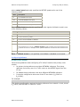
Revision history
Revision Release date
Notes
1.2
January, 1998
SS7 B.1.5
1.3
July, 1998
GJG
1.4
September, 1998 GJG
1.5
March, 1999
GJG
1.6
June, 1999
GJG, SS7 2.1 Beta
1.7
December, 1999 GJG, SS7 2.11
1.8
April, 2000
GJG, SS7 3.5 Beta
1.9
July, 2000
GJG, SS7 3.5
2.0
November, 2000 GJG, SS7 3.6
2.1
August, 2001
GJG, SS7 3.8 Beta
2.2
February, 2002
MVH, SS7 3.8
2.3
November, 2003 MCM, SS7 4.0 Beta
2.4
April, 2004
MCM, SS7 4.0
2.5
April, 2005
MVH, SS7 4.2
2.6
August, 2006
LBZ, SS7 4.3
Last modified: August 9, 2006
Refer to the NMS Communications web site (www.nmscommunications.com) for product updates and for
information about support policies, warranty information, and service offerings.
2
NMS Communications
Table Of Contents
Chapter 1: Introduction .................................................................................7
Chapter 2: Configuration overview ................................................................9
Sample SS7 configurations ........................................................................... 9
Configuration summary ...............................................................................11
Chapter 3: Configuring TDM (TX 4000/C) ....................................................13
TDM configuration overview (TX 4000/C) .......................................................13
Sample TDM configuration files..................................................................13
Common configuration changes .................................................................14
H.100 and H.110 bus clocking overview.........................................................16
Clock masters and clock slaves..................................................................16
Timing references ....................................................................................17
Fallback timing references ........................................................................20
Clock signal summary ..............................................................................20
Board-level clock fallback .........................................................................21
NETREF (NETREF1) and NETREF2...............................................................23
Configuring clocking (TX 4000/C) .................................................................24
Clock command.......................................................................................24
Configuring fallback .................................................................................25
Configuring NETREF .................................................................................26
Configuring T1/E1 trunks (TX 4000/C)...........................................................27
E1 configuration ......................................................................................27
T1 and J1 configuration ............................................................................30
Configuring ports (TX 4000/C) .....................................................................34
Local stream mapping scheme...................................................................34
Port command ........................................................................................35
Connect command ...................................................................................36
Examples ...............................................................................................37
Chapter 4: Configuring TDM (TX 3220/C) ....................................................41
TDM configuration overview (TX 3220/C) .......................................................41
Sample TDM configuration files..................................................................41
Common configuration changes .................................................................42
Configuring clocking (TX 3220/C) .................................................................43
Configuring T1/E1 trunks (TX 3220/C)...........................................................44
Configuring ports (TX 3220/C) .....................................................................45
Generating the binary file ............................................................................46
Chapter 5: Configuring MTP .........................................................................47
MTP configuration overview .........................................................................47
MTP configuration considerations ...............................................................49
Creating the MTP configuration.....................................................................49
Sample MTP 3 configuration file .................................................................50
MTP 3 configuration file structure...............................................................51
Configuring routes to non-adjacent nodes ......................................................53
Using priorities...........................................................................................55
Using routing masks ...................................................................................57
NMS Communications
3
Introduction
NMS SS7 Configuration Manual
Configuring multiple OPC emulation ..............................................................59
Configuring multiple OPC emulation for a single network ...............................59
Emulating different point codes to directly connected signaling points .............62
Configuring multiple OPC emulation for multiple networks .............................64
Configuring MTP for the Japan-NTT variant ....................................................65
Configuring MTP for the Japan-TTC variant.....................................................67
Configuring high speed links (HSL) ...............................................................70
Parameters.............................................................................................70
High speed link configuration example ........................................................70
MTP configuration reference.........................................................................71
General parameters .................................................................................71
Link parameters ......................................................................................74
Network service access point (NSAP) parameters .........................................81
Routing parameters .................................................................................81
Linkset parameters ..................................................................................83
Chapter 6: Configuring ISUP ........................................................................85
ISUP configuration overview ........................................................................85
Creating the ISUP configuration....................................................................86
Sample ISUP configuration file...................................................................87
Configuring ISUP for the Japan-NTT variant ...................................................88
ISUP configuration reference........................................................................89
General parameters .................................................................................89
SAP parameters ......................................................................................92
NSAP parameters ....................................................................................94
Circuit group parameters ..........................................................................94
Chapter 7: Configuring SCCP........................................................................97
SCCP configuration overview........................................................................97
Creating the SCCP configuration ...................................................................99
Sample SCCP configuration file ..................................................................99
Using default routing ................................................................................ 103
Enabling default routing ......................................................................... 103
Impact of default routing on SCCP message routing ................................... 104
Impact of default routing on SCCP management ........................................ 104
SCCP limitations when default routing is enabled ....................................... 105
Configuring global title translations ............................................................. 106
Multiple originating point codes (OPC) ......................................................... 108
MTP multiple OPC configuration ............................................................... 108
Configuring multiple OPC emulation for a single network ............................. 108
Configuring multiple OPC emulation to multiple networks ............................ 109
SCCP configuration reference ..................................................................... 110
General parameters ............................................................................... 110
User SAP parameters ............................................................................. 113
Network SAP parameters ........................................................................ 115
Address translation parameters ............................................................... 116
Route parameters.................................................................................. 117
4
NMS Communications
NMS SS7 Configuration Manual
Introduction
Chapter 8: Configuring TCAP......................................................................119
TCAP configuration overview ...................................................................... 119
Creating the TCAP configuration ................................................................. 120
Sample TCAP configuration file ................................................................ 120
TCAP configuration reference ..................................................................... 121
General parameters ............................................................................... 121
User SAP parameters ............................................................................. 122
Chapter 9: Configuring TUP........................................................................125
TUP configuration overview........................................................................ 125
Creating the TUP configuration ................................................................... 126
Sample TUP configuration file .................................................................. 127
TUP configuration reference ....................................................................... 128
General parameters ............................................................................... 128
User SAP parameters ............................................................................. 131
Network SAP parameters ........................................................................ 131
Circuit and circuit group parameters......................................................... 132
Chapter 10: Downloading the configurations............................................135
Starting txalarm....................................................................................... 135
Downloading to the boards ........................................................................ 135
Using ss7load........................................................................................ 136
Sample ss7load for Windows ................................................................... 137
Sample ss7load for UNIX ........................................................................ 140
Monitoring link status................................................................................ 143
Troubleshooting link problems.................................................................... 144
NMS Communications
5
1
Introduction
The NMS SS7 Configuration Manual explains how to configure NMS SS7 and bring
the links into service. This manual discusses the following configurations:
•
TDM channels
•
MTP 2 and 3 layers
•
Optional ISUP, SCCP, TCAP, and TUP layers
NMS Communications
7
2
Configuration overview
Sample SS7 configurations
Depending on the physical hardware configuration of your TX boards, the SS7 link
interface between the boards can be one of the following:
•
A single timeslot on one of the T1/E1 trunks. TX 3220/C boards require a
dual-T1 or dual-E1 daughterboard or a rear transition board. TX 4000/C
boards include an on-board quad T1/E1 interface.
•
All of the timeslots on a T1/E1 trunk. High speed links (HSL) meet the ANSI
T1.111-1996 and Q.703/Annex A standards. Each HSL occupies a full
(unchannelized) T1/E1 line and transfers data at the rate of 2.0 (1.544) Mbps.
•
A single timeslot on the H.100/H.110 bus.
•
A V.35 serial link. The V.35 connection option is provided only on TX 3220/C
boards and requires a V.35 serial daughterboard or a rear transition board.
NMS SS7 provides the following sample configurations that you can modify for your
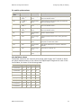
specifications:
Configuration type
Location
ANSI standalone
\nms\tx\config\standalone\ansi for a Windows system
/opt/nmstx/etc/standalone/ansi for a UNIX system
ANSI redundant
\nms\tx\config\redundant\ansi for a Windows system
/opt/nmstx/etc/redundant/ansi for a UNIX system
ITU standalone
\nms\tx\config\standalone\itu for a Windows system
/opt/nmstx/etc/standalone/itu for a UNIX system
ITU redundant
\nms\tx\config\redundant\itu for a Windows system
/opt/nmstx/etc/redundant/itu for a UNIX system
NMS Communications
9
Configuration overview
NMS SS7 Configuration Manual
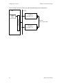
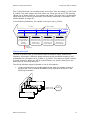
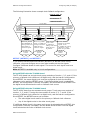
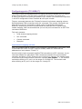
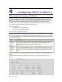
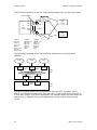
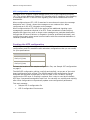
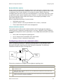
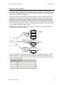
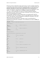
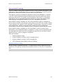
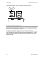
The following illustration shows the ANSI standalone sample configuration:
PC bus
Host
TX board 1
txalarm
Point code 1.1.1
utility
TX device driver
SS7 link
(T1/E1 crossover cable)
TX board 2
Point code 1.1.2
10
NMS Communications
NMS SS7 Configuration Manual
Configuration overview
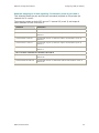
Configuration summary
Before starting the NMS SS7 configuration, complete the following installations:
Step
Description
For details, refer to...
1
Install the TX board
The appropriate board installation manual.
2
Install the Natural Access development
environment under Windows or UNIX.
The Natural Access Installation booklet and the
Natural Access Developer's Reference Manual.
3
Install the NMS SS7 software
The NMS SS7 Installation booklet.
Then follow these steps to configure NMS SS7 and bring the links into service:
Step
Description
For details, refer to...
1
To use T1/E1 trunks or H.100/H.110 bus channels as
the physical SS7 links, configure the streams and
timeslots to carry the SS7 links.
TDM configuration overview (TX
4000/C) on page 13
2
Configure the MTP layers.
MTP configuration overview on
page 47
3
Configure the optional layers.
ISUP configuration overview on
page 85
SCCP configuration overview on
page 97
TCAP configuration overview on
page 119
TUP configuration overview on
page 125
4
Start the txalarm utility on the host to monitor the
status of the links.
Starting txalarm on page 135
5
Download the appropriate configurations to the TX
boards.
Downloading to the boards on
page 135
6
Check the txalarm messages to see that the links come
into service on the boards.
Monitoring link status on page 143
7
Troubleshoot any problems indicated in the txalarm
messages.
Troubleshooting link problems on
page 144
NMS Communications
TDM configuration overview (TX
3220/C) on page 41
11
3
Configuring TDM (TX 4000/C)
TDM configuration overview (TX 4000/C)
Before T1/E1 trunks or H.100/H.110 bus channels (also known as TDM channels) can
be used for physical SS7 links, you must download a TDM configuration to the TX
board. To configure a TX 4000/C board, create a TDM configuration file (txcfgn.txt)
that defines TDM clocking control, configures all T1/E1 trunks, and defines all
dedicated data channels. Each TX board in a system requires a separate TDM
configuration file.
The NMS TDM configuration utility, txconfig, runs as part of the initial board
configuration with ss7load. txconfig reads the TDM configuration file and downloads
the specified configuration to the TX 4000/C board.
This topic presents:
•
Sample TDM configuration files
•
Common configuration changes
Sample TDM configuration files
NMS SS7 provides the following sample TDM configuration files for ANSI standalone
and redundant configurations and ITU standalone and redundant configurations that
you can modify for your specifications. The sample TDM configuration files present
the most common type of TX board use.
Files
Description
txcfg1.txt
Configures the first TX 4000/C board in a chassis with four T1 trunks. This configuration
file specifies that the clock signal recovered from the first trunk connection (trunk 1) is
used as the clock source for the TX board. No H.100/H.110 clock signals are driven by this
configuration.
txcfg2.txt
For two TX 4000/C boards in a chassis. This configuration file configures the second board
with the T1 trunks set as loop master. This board is configured as the master clock source
(using the board's internal oscillator). No H.100/H.110 clock signals are driven by this
configuration.
For the location of the sample configuration files, see Sample SS7 configurations on
page 9.
NMS Communications
13
Configuring TDM (TX 4000/C)
NMS SS7 Configuration Manual
The following example shows a txcfg.txt for a TX 4000 board operating in T1 mode:
#
T1 Example
#
Timing Configurations:
#
# use clock recovered from trunk 1 as board’s clock and drive H.100/H.110 A clocks
clock net=1 a
# use clock recovered from trunk 2 as network reference clock (drive NR1 signal)
netref 2 nr1
#
# Configure all 4 trunks as T1 mode (not loop master)
#----------------------------------------------------------------------------#
Trunk
Framing
Encoding
Buildout
Loop Master
t1cfg 1
esf
b8zs
0
false
t1cfg 2
esf
b8zs
0
false
t1cfg 3
esf
b8zs
0
false
t1cfg 4
esf
b8zs
0
false
# define ports that SS7 links will connect through
#----------------------------------------------------------------------------#
PortNum
L|H|E|T|J
Trunk
Channel
Speed
port 1
t1
1
0
port 2
t1
2
23
The following example shows a txcfg.txt for a TX 4000 board operating in E1 mode:
#
E1 Example
#
Timing Configurations:
#
# use clock recovered from trunk 1 as board’s clock and drive H.100/H.110 A clocks
clock net=1 a
# use clock recovered from trunk 2 as network reference clock (drive NR1 signal)
netref 2 nr1
#
# Configure all 4 trunks as E1 mode (not loop master)
#----------------------------------------------------------------------------#
Trunk
Framing
Encoding
Loop Master
e1cfg 1
ccs
hdb3
false
e1cfg 2
ccs
hdb3
false
e1cfg 3
ccs
hdb3
false
e1cfg 4
ccs
hdb3
false
# define ports that SS7 links will connect through
#----------------------------------------------------------------------------#
PortNum
L|H|E|T|J
Trunk
Channel
Speed
port 1
e1
1
1
port 2
e1
2
31
Common configuration changes
The following list provides some common TDM configuration changes required for
different hardware configurations.
14
•
The sample TDM configuration files assume T1 trunks for ANSI configurations
and E1 trunks for ITU configurations. If you use a different trunk type than
the examples use, change the T1/E1 parameter lines to reflect the proper
parameters. For T1 port definitions, the channel number is a zero-based value
identifying the timeslot to access. For T1, channels 0 through 23 are
available, providing access to all 24 timeslots of a T1 trunk. For E1, channels
1 through 31 are available, providing access to the 31 E1 timeslots beyond
timeslot zero. Timeslot zero is used solely for framing on E1 trunks and
cannot be used to transport data such as SS7.
•
To configure a high speed link (HSL), replace the channel number with an
asterisk (*).
NMS Communications
NMS SS7 Configuration Manual
Configuring TDM (TX 4000/C)
•
The sample configuration files contain commented out sections that define
other types of TDM connections, such as E1 for files that default to T1 or
H.100/H.110. To change from T1 to E1 or from T1 to H.100 for example,
comment out the original configuration lines and paste a copy of the desired
example lines, removing the comment character to activate the pasted lines.
•
Modify clocking control based on the specific environment. The sample
configuration file for board 1 (txcfg1.txt) assumes the board receives the
clock signal from the first T1 or E1 trunk, implying that the first trunk is
connected to another trunk that is acting as the loop master. The sample
configuration file for board 2 (txcfg2.txt) configures that board to act as the
loop master for all its T1 or E1 trunks. If this is not the configuration you want
to use, modify the clock statement, or the Loop Master field, or both.
For details on configuring TDM, see the following topics:
•
H.100 and H.110 bus clocking overview on page 16
•
Configuring clocking (TX 4000/C) on page 24
•
Configuring T1/E1 trunks (TX 4000/C) on page 27
•
Configuring ports (TX 4000/C) on page 34
NMS Communications
15
Configuring TDM (TX 4000/C)
NMS SS7 Configuration Manual
H.100 and H.110 bus clocking overview
If the boards in a system are connected to each other on the CT bus, you must set
up a bus clock to synchronize communications between the boards connected to the
bus. To provide redundant and fault-tolerant clocking on the bus, configure
alternative (fallback) clock sources to provide the clock signal if the primary source
fails.
This topic presents:
•
Clock masters and clock slaves
•
Timing references
•
Fallback timing references
•
Clock signal summary
•
Board-level clock fallback
•
NETREF (NETREF1) and NETREF2
These topics present H.100/H.110 clocking as described in the ECTF H.110 Hardware
Compatibility Specification: CT Bus R1.0.
Note: Board clocking procedures are not transparent to the application. In addition
to configuring clocking, the application must monitor clocking and take appropriate
action when required.
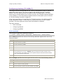
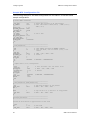
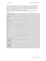
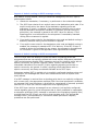
Clock masters and clock slaves
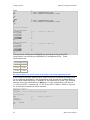
To synchronize data transfer from board to board across the H.100 bus or H.110
bus, boards on the bus must be phase-locked to a high-quality 8 MHz clock and 8
kHz frame pulse. These signals together compose a CT bus clock.
C
T
bu
s
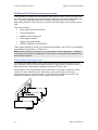
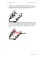
One board on the bus generates (drives) the clock. This board is called the clock
master. All other boards use this clock as a timing reference by which they
synchronize their own internal clocks. These boards are called clock slaves. The
following illustration shows the clock master and clock slaves:
Clock slave
Clock master
Clock slave
Clock slave
16
Clock
pulse
NMS Communications
NMS SS7 Configuration Manual
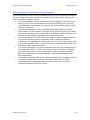
Configuring TDM (TX 4000/C)
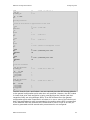
Two CT bus clocks can run simultaneously on the bus. They are called A_CLOCK and
B_CLOCK. The clock master can drive either one. When you set up CT bus clocking,
choose one of these clocks for your master and slaves. The other one is a redundant
signal that can be used by a secondary clock master (described in Secondary clock
master fallback on page 22).
In the following illustration, the system is set up to use A_CLOCK:
CT bus
CT bus clocks
A_CLOCK
B_CLOCK
Clock master
Drives a CT bus
clock based on
a signal from a
timing
reference
Clock slave
Gets its timing
reference from
a CT bus clock
driven by a
clock master
Clock slave
Gets its timing
reference from
a CT bus clock
driven by a
clock master
Clock slave
Gets its timing
reference from
a CT bus clock
driven by a
clock master
Timing
reference
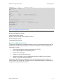
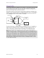
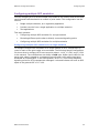
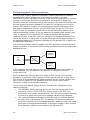
Timing references
To drive its CT bus clock, a clock master takes a reference signal, extracts the
frequency information, defines a phase reference at the extracted frequency, and
broadcasts this information as A_CLOCK or B_CLOCK. This reference signal is called
a timing reference. When you set up a clock master, you specify what source the
board uses as its timing reference.
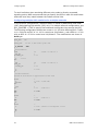
The timing reference signal originates in one of three places:
It can originate within the public network and enter the system through a
digital trunk. This is called a NETWORK timing reference as shown in the
following illustration:
C
T
bu
s
•
Clock slave
Clock master
Clock slave
Signal from
digital trunk
PSTN
Clock slave
NMS Communications
17
Configuring TDM (TX 4000/C)
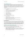
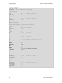
In a system with no digital telephone network interfaces, an on-board
oscillator can be used as the timing reference to drive the clock signals. This
is called an OSC timing reference and is shown in the following illustration.
Use OSC only if there is no external clock source available.
C
T
bu
s
•
NMS SS7 Configuration Manual
Clock slave
Clock master
Clock slave
Clock slave
The timing reference used by a clock master to drive the CT bus clock can
also originate from an oscillator or trunk connected to another device in the
system. In this case, the timing reference signal is carried over the CT bus to
the clock master, which derives the clock signal and drives the clock for the
slaves. The following illustration shows a timing reference from another
device:
C
T
bu
s
•
Clock slave
Clock master
Clock signal
Clock slave
Clock slave
18
NMS Communications
NMS SS7 Configuration Manual
Configuring TDM (TX 4000/C)
The channel over which the timing reference signal is carried to the clock
master is called NETREF, as shown in the following illustration:
Timing reference
channel
CT bus clocks
CT bus
A_CLOCK
B_CLOCK
NETREF
Primary clock
master
Driving A_CLOCK
based on timing
reference signal
from NETREF
Clock
slave
Clock slave
Driving timing
reference signal on
NETREF based on
external timing
reference
Clock
slave
Timing reference
(digital trunk)
On the H.110 bus, a second timing reference signal can be carried on a fourth
channel, called NETREF2 as shown in the following illustration. NETREF is
referred to as NETREF1 in this case.
CT bus clocks
Timing reference
channels
H.110 bus
A_CLOCK
B_CLOCK
NETREF1
NETREF2
Primary clock
master
Driving A_CLOCK
based on timing
reference signal
from NETREF1
Clock
slave
Clock slave
Driving timing
reference signal
on NETREF1
based on
external timing
reference
Clock slave
Driving timing
reference signal on
NETREF2 based on
external timing
reference
Timing reference
(digital trunk)
Timing reference
(digital trunk)
NMS Communications
19
Configuring TDM (TX 4000/C)
NMS SS7 Configuration Manual
Fallback timing references
Boards can optionally be assigned a backup (fallback) timing reference that it can
use if its primary timing reference fails. For a clock master, the source for the
fallback timing reference must be a different source than the one currently used by
the clock master for its primary timing reference.
For example, if a clock master's primary timing reference source is a NETWORK
signal from one of its trunks, the fallback timing reference source can be a NETWORK
signal from another one of its trunks, or a signal from NETREF1, NETREF2 (if H.110),
or OSC. In the following illustration, the fallback timing reference source is NETREF1.
CT bus clocks
H.110 bus
Timing
reference
channels
A_CLOCK
B_CLOCK
NETREF1
NETREF2
Primary clock master
Ordinarily drives
A_CLOCK based on
timing reference from
digital trunk; now
using NETREF1
Clock
slave
Non-functional digital
trunk, ordinarily used
as primary timing
reference
Clock slave
Driving timing
reference signal
on NETREF1 based
on external timing
reference
Clock
slave
Timing reference
(digital trunk)
The ability of a board to automatically switch to its fallback timing reference if its
primary timing reference fails is called clock fallback. This feature can be enabled or
disabled.
Clock signal summary
The following table summarizes the reference clocks that a clock master can drive:
Clock
Details
A_CLOCK
The set of primary bit clocks (CT8A) and framing signals (CTFrameA). The CT8A signal is an
8 MHz clocking reference for transferring data over the CT bus. The CTFrameA provides a
low going pulse signal every 1024 (8 MHz) clock cycles.
B_CLOCK
The set of secondary bit clocks (CT8B) and framing signals (CTFrameB). The CT8B signal is
an 8 MHz clocking reference for transferring data over the CT bus. The CTFrameB provides a
low going pulse signal every 1024 (8 MHz) clock cycles.
20
NMS Communications
NMS SS7 Configuration Manual
Configuring TDM (TX 4000/C)
The following table summarizes the timing references that a clock master can use:
Timing
reference
Details
NETWORK
The timing signal from a digital trunk attached to the clock master board. Within the
digital trunk interface, an 8 kHz reference is derived from the frequency of the
incoming signal. The clock master is frequency-locked to this 8 kHz reference so that
the long-term timing of the system matches that of the public telephone network.
Note: No timing signal is available from an analog trunk.
NETREF/NETREF1
The CTNETREF_1 signal. This signal can be 8 kHz, 1.544 MHz, or 8 MHz. NMS
recommends using only 8 kHz signals for most boards.
NETREF2
(H.110 only) The CTNETREF_2 signal. This signal can be 8 kHz, 1.544 MHz, or 8
MHz. NMS recommends using only 8 kHz signals for most boards.
OSC
Clock signal derived from an oscillator on the clock master board.
Note: Use this timing reference source only if no network timing references are
available.
Board-level clock fallback
The TX 4000/C board can be configured to perform in any one of the following
fallback roles:
•
Primary clock master
•
Secondary clock master
•
Clock slave
The clock fallback role a TX board takes is based on how the main clocking
parameters are configured. If no fallback clock is configured, the TX board does not
participate in any fallback behavior. For more information, see Configuring clocking
(TX 4000/C) on page 24.
Primary clock master fallback
Clock fallback for a primary clock master works as follows:
1. The primary clock master synchronizes with its primary network timing
reference and drives the primary CT bus clock.
2. If the primary network reference fails, the clock master continues to drive the
primary CT bus clock, but switches to the fallback network timing reference as
its synchronization source.
3. If the secondary timing reference fails, the primary clock master stops driving
the primary CT bus clock, and falls back to the secondary CT bus clock, which
is now driven by the secondary clock master off its fallback timing reference.
4. If the secondary CT bus clock fails, the board falls back to its internal
oscillator and continues to monitor the state of the secondary CT bus clock.
5. If the secondary CT bus clock is reestablished, the board synchronizes again
with the secondary CT bus clock.
NMS Communications
21
Configuring TDM (TX 4000/C)
NMS SS7 Configuration Manual
Secondary clock master fallback
You can set up a second device to be used as a backup or a secondary clock master
if the primary clock master stops driving its CT bus clock (because both of its timing
references failed, or it was hot-swapped out).
Clock fallback for a secondary clock master works as follows:
1. As long as the primary clock master is driving its CT bus clock, the secondary
clock master acts as a slave to the primary clock master. However, the
secondary master also drives the CT bus clock not driven by the primary
master (for example, B_CLOCK if the primary master is driving A_CLOCK).
2. If the primary clock master stops driving its CT bus clock, all slaves (including
the secondary clock master) lose their primary timing reference.
3. This failure triggers the secondary master to fall back to its fallback timing
reference and continue to drive the secondary CT bus clock from the fallback
reference.
4. This failure also triggers other slaves to fall back to the CT bus clock driven by
the secondary clock master.
5. The secondary master and slaves do not switch back to the primary timing
reference automatically if the primary reference is reestablished. Software
intervention is required prior to any further clock changes.
6. If the board formerly used as the primary clock master is still active but is not
receiving a primary or fallback timing reference, the board becomes a slave to
the clock driven by the secondary master.
7. If the secondary clock master’s fallback clock reference fails, it switches to an
internal oscillator and continues to drive the secondary CT bus clock.
8. Upon recovery of the fallback clock reference, the secondary clock master
synchronizes again with the clock reference and continues to drive the
secondary CT bus clock based on the fallback reference.
Clock slave fallback
Clock fallback for a clock slave works as follows:
1. As long as the primary clock master is driving its CT bus clock, the clock slave
uses this clock.
2. Upon detecting failure of the primary CT bus clock, the clock slave switches to
the secondary CT bus clock.
3. If the secondary CT bus clock fails, the board falls back to its internal
oscillator and continues to monitor the state of the secondary CT bus clock.
4. If the secondary CT bus clock is reestablished, the board synchronizes again
with the secondary CT bus clock.
22
NMS Communications
NMS SS7 Configuration Manual
Configuring TDM (TX 4000/C)
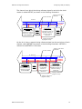
The following illustration shows a sample clock fallback configuration:
Driving clock
Clock source
Fallback clock source
H.110 Bus
A_CLOCK
A_CLOCK
B_CLOCK
B_CLOCK
NETREF
NETREF
NETREF2
NETREF2
Board A
Primary clock
master
(Network board)
Drives A_CLOCK.
Uses NETREF as
timing reference.
Falls back to
network signal.
Network
(trunk
connection)
Board B
Secondary clock
master
(Network board)
Drives B_CLOCK.
Uses A_CLOCK as
timing reference.
Falls back to
network signal.
Board D
Clock slave
Board C
Clock slave
(Network board)
Does not drive a
clock. Uses
A_CLOCK as
timing reference.
Falls back to
B_CLOCK.
Network
(trunk
connection)
Drives NETREF
based on network
signal. Uses
A_CLOCK as timing
reference. Falls
back to B_CLOCK.
Network
(trunk
connection)
NETREF (NETREF1) and NETREF2
If you specify that any board use NETREF (NETREF1) or NETREF2 as a timing
reference, you must configure one or two other boards to drive the signals.
Configure a different board for each signal. The source for each signal must be a
digital trunk.
Note: NETREF2 is available only in H.110 configurations.
Using NETREF with the TX 4000 board
The TX 4000 board has a single trunk group consisting of trunks 1, 2, 3, and 4. If the
primary or fallback clock reference is a digital trunk, and the board is configured to
drive NETREF, the same digital trunk must be configured for both the clocking
reference source and the NETREF source. If a different digital trunk is selected for
NETREF, this configuration is silently overridden, and the board drives NETREF from
the digital trunk selected as the main or fallback clock source.
Using NETREF with the TX 4000C board
The TX 4000C board has two separate trunk groups. Trunk group one consists of
trunks 1, 2, 5, and 6. Trunk group two consists of trunks 3, 4, 7, and 8. If the
primary or fallback clock reference is a digital trunk, and the board is configured to
drive NETREF, the NETREF source can be either:
•
The same digital trunk used for the primary or fallback clock reference
•
Any of the digital trunks in the other trunk group
If a different digital trunk in the same trunk group is selected to drive NETREF, this
configuration is silently overridden, and the board drives NETREF from the digital
trunk selected as the main or fallback clock source.
NMS Communications
23
Configuring TDM (TX 4000/C)
NMS SS7 Configuration Manual
Configuring clocking (TX 4000/C)
The txcfg.txt clock command defines the clocking configuration of the TX 4000/C
board main clock source. This clock is used as the internal clock for TX 4000/C
boards. The clock signal can also be routed to other clocking signals. The clock
source can be a clock signal of the H.100/H.110 bus, the TX board internal oscillator,
or an oscillator or trunk connected to another device in the system (see H.100 and
H.110 bus clocking overview on page 16).
If the clock command is not specified, the TX board remains in its default clocking
mode (standalone mode). In this mode, the main clock source is the on-board
oscillator. No clock signals are driven and clock fallback is disabled.
This topic presents:
•
Clock command
•
Configuring fallback
•
Configuring NETREF
Clock command
The clocking configuration statement syntax is:
clock source [=network] outsigs [netref speed] [fallback source [=fallback network]]
where source specifies the source of the timing reference signal and is one of the
following values:
Value
Description
a
H.100/H.110 bus A_CLOCK.
b
H.100/H.110 bus B_CLOCK.
nr1
H.100/H.110 bus NETREF or NETREF1.
nr2
H.100/H.110 bus NETREF2.
net
Clock derived from external network connection (T1/E1 trunk).
When specifying net, use the =network syntax to identify from which network trunk to
extract the clock. For example, clock net=1 specifies using the clock derived from network
trunk 1 as the board’s clock source.
osc
On-board oscillator.
where outsigs specifies the clock signal to drive and is one of the following values:
Value
Description
a
Drive H.100/H.110 bus A_CLOCK.
b
Drive H.100/H.110 bus B_CLOCK.
-
Do not drive any H.100/H.110 bus A_CLOCK or B_CLOCK.
24
NMS Communications
NMS SS7 Configuration Manual
Configuring TDM (TX 4000/C)
where netref speed optionally specifies the NETREF speed and is one of the
following values:
Value
Description
8k
8 kHz NETREF clock signal.
15m
1.544 MHz NETREF clock signal.
20m
2.048 MHz NETREF clock signal.
-
Speed of NETREF clock signal not provided.
where fallback source optionally specifies the clock signal to fall back to and is one
of the following values:
Value
Description
a
H.100/H.110 bus A_CLOCK.
b
H.100/H.110 bus B_CLOCK.
nr1
H.100/H.110 bus NETREF or NETREF1.
nr2
H.100/H.110 bus NETREF2.
net
Clock derived from external network connection (T1/E1 trunk).
When specifying net, use the =fallback network syntax to identify from which network trunk
to extract the clock. For example, net=1 specifies fallback to clock derived from network trunk
1.
osc
On-board oscillator.
Note: If fallback source is not specified, clock fallback is disabled on the board.
Configuring fallback
Primary clock master
Follow these guidelines when configuring a TX 4000/C board as the primary clock
master:
•
Its primary timing reference must be a NETWORK reference. This timing
reference can be any one of its T1/E1 trunks or the NETREF signal from the
CT bus.
•
Its fallback timing reference must be a different NETWORK reference.
•
It must be configured to drive one of the CT bus clocks (A_CLOCK or
B_CLOCK).
For example:
clock net=1 a - net=2
This clocking configuration receives the timing reference from network 1 clock, drives
A_CLOCK, and falls back to network 2 clock.
NMS Communications
25
Configuring TDM (TX 4000/C)
NMS SS7 Configuration Manual
Secondary clock master
Follow these guidelines when configuring a TX 4000/C board as the secondary clock
master:
•
It must receive its primary timing reference from the CT bus clock driven by
the primary clock master (either A_CLOCK or B_CLOCK).
•
It must drive the CT bus clock not driven by the primary master. For
example, if the primary clock master is driving A_CLOCK, the secondary clock
master must drive B_CLOCK. In this case, both clocks are synchronized.
•
It must have a fallback timing reference. This timing reference must not be
the primary clock master's primary or fallback timing reference.
For example:
clock a b - net=1
This clocking configuration receives the timing reference from A_CLOCK, drives
B_CLOCK, and falls back to network 1 clock.
Clock slave
Follow these guidelines when configuring a TX 4000/C board as the clock slave:
•
The primary clock source is the primary CT bus clock driven by the primary
clock master.
•
The fallback clock source is the secondary CT bus clock driven by the
secondary clock master.
For example:
clock a - - b
This clocking configuration receives the timing reference from A_CLOCK and falls
back to B_CLOCK.
Configuring NETREF
Use the txcfg.txt netref command to route a clock signal recovered from a specified
T1/E1 network connection to the indicated H.100/H.110 bus NETREF signals. If the
netref command is not specified, the TX 4000/C board does not drive any of the
H.100/H.110 NETREF clock signals.
The NETREF clocking configuration statement syntax is:
netref network outsigs [netref speed]
where network is the network number (T1/E1 trunk number) from which to derive
the clock signal, and outsigs specifies the clock signal to drive and is one of the
following values:
Value
Description
nr1
Drive H.100/H.110 bus NETREF or NETREF1.
nr2
Drive H.100/H.110 bus NETREF2.
nr12
Drive H.100/H.110 bus NETREF1 AND NETREF2.
-
Do not drive any H.100/H.110 bus NETREF signal.
26
NMS Communications
NMS SS7 Configuration Manual
Configuring TDM (TX 4000/C)
where netref speed optionally specifies the NETREF speed and is one of the
following values:
Value
Description
8k
8 kHz NETREF clock signal.
15m
1.544 MHz NETREF clock signal.
20m
2.048 MHz NETREF clock signal.
-
Speed of NETREF clock signal not provided.
Configuring T1/E1 trunks (TX 4000/C)
The txcfg.txt T1/E1 configuration command determines whether a TX 4000/C board's
trunk is configured as E1 (e1cfg), T1 (t1cfg), or J1 (j1cfg) mode. The configuration
command consists of an identifier for the trunk being configured (1 through 4 for TX
4000, 1 through 8 for TX 4000C) and parameters specifying the circuit framing, line
encoding, line buildout (T1/J1 only), and loop master configuration. This
configuration statement defines the most common attributes of a trunk interface.
Each T1/E1 command also supports an optional command that can be used to
configure less common options for the given trunk type (E1 (e1opt), T1 (t1opt), J1
(j1opt)). Options must be specified before the trunk configuration command is
specified.
This topic presents:
•
E1 configuration
•
T1 and J1 configuration
E1 configuration
Use the txcfg.txt e1cfg command to configure a trunk as an E1 interface. The
information provided by the e1cfg command is combined with any information
provided in previous e1opt commands to produce the full E1 trunk configuration
information.
The E1 trunk configuration statement syntax is:
e1cfg trunk_num framing encoding master
where trunk_num is the trunk number to configure (1 through 4 for TX 4000, 1
through 8 for TX 4000C) and framing is one of the following values:
Value
Description
ccs
Clear channel signaling (double frame format).
cas
Channel associated signaling.
ccsrc
Clear channel signaling (CRC4 multiframe format).
casrc
Channel associated signaling (CRC4 multiframe format).
NMS Communications
27
Configuring TDM (TX 4000/C)
NMS SS7 Configuration Manual
where encoding is one of the following values:
Value
Description
nozcs
AMI encoding with no zero code suppression.
hdb3
High density bipolar order 3.
where master is one of the following values:
Value
Description
true
Local side of connection acts as timing source for this circuit.
false
Remote side of connection acts as timing source.
E1 options
Use the e1opt command to control all E1 trunk configuration options that are not
specified by the e1cfg command. The e1opt command does not send configuration
requests to the TX board; the command modifies the optional configuration
information attached to the E1 trunk configuration request issued by the e1cfg
command. Because the E1 configuration options are not reset by an e1cfg command,
all E1 options can be specified once and used for the configuration of each E1 trunk.
A single e1opt command can be used to set up to 15 different options. Multiple e1opt
commands can also be used.
The E1 trunk configuration options statement syntax is:
e1opt ! flag name value name=value
where
Parameter
Description
!
Clear a flag. Use to disable an option that is enabled by default.
flag name
Flag to set, or clear if ! is specified. See E1 option flags.
value name
Value to change. See E1 option values.
value
New value for named parameter.
E1 option flags
The following table lists the E1 option flags. If the default of the specified option flag
is SET, use ! flag name to clear the flag.
Flag
name
Description
EXZE
Extended code violation or excessive zero detection.
ALM
Standard by which AIS is detected. SET = ITU-T G.775; CLEAR = ETS300233. Default is
SET.
SA6Y
Detection of Sa6-bit pattern done synchronously to multiframe.
EXTIW
Extended CRC4 to non-CRC4 interworking (search after 400 ms). Default is SET.
AXRA
Remote alarm bit set automatically if receiver in asynchronous state. Default is SET.
CRCI
Automatic CRC (4) bit inversion.
28
NMS Communications
NMS SS7 Configuration Manual
Configuring TDM (TX 4000/C)
Flag
name
Description
XCRCI
Transmission of CRC (4|6) bit inversion.
DCOXC
Center function of transmission circuitry enabled.
ALMF
Automatic loss of multiframe alignment when excessive CRC errors. Default is SET.
AXS
Automatic transmission of submultiframe status. Default is SET.
EBP
In asynchronous state, E-bit is set (valid only if AXS is set). Default is SET.
DAIS
Automatic AIS insertion disabled.
DAXLT
Automatic high impedance transmission pins on short detect disabled.
DXJA
Internal transmit jitter attenuation disabled.
DCF
Center function of receive circuitry disabled.
AFR
Automatic search for double frame alignment disabled.
XSIS
First bit of the service word. Default is SET.
XSIF
Transmission of spare bit for international use (FAS word). Default is SET.
XS13
Transmission of spare bit (frame 13, CRC-multiframe). Default is SET.
XS15
Transmission of spare bit (frame 15, CRC-multiframe). Default is SET.
SWD
Loss of synchronization based on service word disabled.
ASY4
Four consecutive incorrect FAS words cause LOS (CLEAR = 3).
EQON
-43 dB receiver (long hall mode). CLEAR = -10 dB (short haul).
RLM
Receiver mode for receive line monitoring.
CLOS
Received data is cleared as soon as LOS detected.
SCF
Corner frequency of DCO-R reduced by factor of 10 to 0.2 Hz.
NMS Communications
29
Configuring TDM (TX 4000/C)
NMS SS7 Configuration Manual
E1 option values
Option
name
Default
Valid range
Description
XP0
0x14
0x00 through
0x1F
Transmission of pulse shape mask (for 1st level).
XP1
0x13
0x00 through
0x1F
Transmission of pulse shape mask (for 2nd level).
XP2
0x00
0x00 through
0x1F
Transmission of pulse shape mask (for 3rd level).
XP3
0x00
0x00 through
0x1F
Transmission of pulse shape mask (for 4th level).
RIL
0x02
0x00 through
0x07
Receive input threshold.
SLT
0x02
0x00 through
0x03
Voltage threshold when receive slicer generates mark.
PCD
0x0A
0x00 through
0xFF
LOS alarm generated if no transmission in 16x(pcd+1)
consecutive pulses.
PCR
0x15
0x00 through
0xFF
LOS alarm cleared if pcr+1 pulses in detect interval.
XY
0x1F
0x00 through
0x1F
Spare bits for national use.
T1 and J1 configuration
Use the txcfg.txt t1cfg command to configure a trunk as a T1 interface. The
information provided by the t1cfg command is combined with information provided in
previous t1opt commands to produce the full T1 trunk configuration information. As
a variant of the standard T1 trunk configuration, use the j1cfg command to configure
the trunk in J1 mode. The syntax for both the t1cfg and the j1cfg commands is
identical.
The T1 trunk configuration statement syntax is:
t1cfg trunk_num framing encoding build_out master
The J1 trunk configuration statement syntax is:
j1cfg trunk_num framing encoding build_out master
where trunk_num is the trunk number to configure (1 through 4 for TX 4000, 1
through 8 for TX 4000C) and framing is one of the following values:
Value
Description
d4
D4 (193S) framing: 12-frame multiframe format (F12, D3/4).
f4
4-frame multiframe format (F4).
esf
Extended superframe format: 24-frame multiframe format (ESF).
f72
72-frame multiframe format (F72, remote switch mode).
30
NMS Communications
NMS SS7 Configuration Manual
Configuring TDM (TX 4000/C)
where encoding is one of the following values:
Value
Description
nozsc
AMI encoding with no zero code suppression.
b7zs
Bit 7 stuffing with zero code suppression.
b8zs
Bipolar eight zero substitution.
where build_out is one of the following values:
Value
Transmitter attenuation
0
0 dB
1
-7.5 dB
2
-15 dB
3
-22.5 dB
where master is one of the following values:
Value
Description
true
Local side of connection acts as timing source for this circuit.
false
Remote side of connection acts as timing source.
T1 and J1 options
Use the t1opt or j1opt command to control all T1 or J1 trunk configuration options
that are not specified by the t1cfg or j1cfg command. The t1opt or j1opt command
does not send configuration requests to the TX board; the command modifies the
optional configuration information attached to the T1 or J1 trunk configuration
request issued by the t1cfg or j1cfg command. Because the T1 and J1 configuration
options are not reset by a t1cgf or a j1cfg command, all T1 or J1 options can be
specified once and used for the configuration of each T1 or J1 trunk. A single t1opt or
j1opt command can be used to set up to 15 different options. Multiple t1opt or j1opt
commands can also be used.
The T1 trunk configuration options statement syntax is:
t1opt ! flag name value name=value
The J1 trunk configuration options statement syntax is:
j1opt ! flag name value name=value
where
Parameter
Description
!
Clear a flag. Use to disable an option that is enabled by default.
flag name
Flag to set, or clear if ! is specified. See T1 and J1 option flags.
value name
Value to change. See T1 and J1 option values.
value
New value for named parameter.
NMS Communications
31
Configuring TDM (TX 4000/C)
NMS SS7 Configuration Manual
T1 and J1 option flags
The following table lists the T1 and J1 option flags. If the default of the option flag is
SET, use ! flag name to clear.
Flag
name
Description
EXZE
Extended code violation or excessive zero detection.
SRAF
F12: FS-bit of frame 12; ESF: bit 2 = 0.
CRC
CRC6 check or generation (ESF format only) enabled. Default is SET.
AIS3
AIS detection only in asynchronous state.
SSC2
LFA declaration if more than 320 CRC6 errors per second.
RRAM
Detection of remote (yellow) alarm allowed during bit error rates.
LOS1
Additional condition for LOS alarm cleared: GR-499-CORE.
SJR
Alarm handling done according to ITU-T JG.704 and 706. Default is CLEAR (T1) and SET
(J1).
AXRA
Remote alarm bit set automatically if receiver in asynchronous state. Default is SET.
CRCI
Automatic CRC(4) bit inversion.
XCRCI
Transmission of CRC(4|6) bit inversion.
DCOXC
Center function of transmit circuitry enabled.
DAIS
Automatic AIS insertion disabled.
DAXLT
Automatic high impedance transmission pins on short detect disabled.
DXJA
Internal transmit jitter attenuation disabled.
DCF
Center function of receive circuitry disabled.
EQON
-36 dB receiver (long haul mode). CLR = -10 dB ( short haul).
RLM
Receiver mode for receive line monitoring.
CLOS
Received data is cleared as soon as LOS detected.
SCF
Corner frequency of DCO-R reduced by a factor of 10 to 0.6 Hz.
MCSP
Multiple candidates synchronization procedure.
SSP
Synchronization procedure.
32
NMS Communications
NMS SS7 Configuration Manual
Configuring TDM (TX 4000/C)
T1 and J1 option values
Option
name
Default
Valid range
Description
XP0
T1_XPM_0
(0xFF)
0x00 through
0x1F
Transmission of pulse shape mask (for 1st level).
See Line buildout values.
XP1
T1_XPM_1
(0xFF)
0x00 through
0x1F
Transmission of pulse shape mask (for 2nd level).
See Line buildout values.
XP2
T1_XPM_2
(0xFF)
0x00 through
0x1F
Transmission of pulse shape mask (for 3rd level).
See Line buildout values.
XP3
T1_XPM_3
(0xFF)
0x00 through
0x1F
Transmission of pulse shape mask (for 4th level).
See Line buildout values.
RIL
0x00
0x00 through
0x07
Receive input threshold.
SLT
0x02
0x00 through
0x03
Voltage threshold when receive slicer generates
mark.
PCD
0x00
0x00 through
0xFF
LOS alarm generated if no transmission in
16x(pcd+1) consecutive pulses.
PCR
0x00
0x00 through
0xFF
LOS alarm cleared if pcr+1 pulses in detection
interval.
XY
0x00
0x00 through
0x1F
Spare bits for national use.
SSC
0x00
0x00 through
0x03
Synchronization conditions.
Line buildout values
The default values for the transmit pulse shape mask trigger the TX board to define
the pulse shape according to the value of the EQON option flag and the value of the
line buildout, as shown in the following table:
Line buildout
XP0
XP1
XP2
XP3
0 (short haul)
17
16
4
1
1 (short haul)
18
17
6
2
2 (short haul)
20
18
7
1
3 (short haul)
23
19
10
1
0 (long haul)
0
0
0
0
1 (long haul)
12
12
0
0
2 (long haul)
12
12
4
2
3 (long haul)
7
8
0
0
NMS Communications
33
Configuring TDM (TX 4000/C)
NMS SS7 Configuration Manual
Configuring ports (TX 4000/C)
The txcfg.txt port command defines a full-duplex connection between the TX 4000/C
board communication controller and a remote SS7 connection over either the
H.100/H.110 bus or over one of the board’s T1/E1 trunks. Port numbers are specified
in the MTP configuration file as Tn where n is the port number.
The port command abstracts the TX board’s internal local stream mapping scheme.
Define dedicated TDM connections with this command. The connect command is an
alternative to the port command to define a pair of half-duplex connections.
However, because the connect command does not abstract the TX board’s local
stream mapping, NMS recommends that you use the port command for all SS7 TDM
connection definitions.
This topic presents:
•
Local stream mapping scheme
•
Port command
•
Connect command
•
Examples
Local stream mapping scheme
Each TX board provides a number of SS7 resources (communication controllers) used
to terminate SS7 links. For the TX 4000/C boards, these SS7 resources are
addressed on local streams 72 and 73.
Use the txcfg.txt port command to define TDM connections to SS7 resources. A port
command creates two half-duplex TDM connections between the communication
controller and either a T1/E1 channel or an H.100/H.110 channel. The timeslot used
to connect to the communication controller is always port number - 1. The timeslot
used when defining a T1 port is in the range of 0 through 23. The timeslot used
when defining an E1 port is in the range of 1 through 31.
34
NMS Communications
NMS SS7 Configuration Manual
Configuring TDM (TX 4000/C)
The following table presents the local stream mapping scheme:
Trunk connections (T1 or J1
trunks)
Trunk connections (E1 trunks)
SS7 communication controller
Trunk
Trunk
Trunk
Trunk
13,
Trunk
17,
Trunk
21,
Trunk
25,
Trunk
29,
1:
2:
3:
4:
Trunk
Trunk
Trunk
Trunk
13,
Trunk
17,
Trunk
21,
Trunk
25,
Trunk
29,
1:
2:
3:
4:
Streams
Streams
Streams
Streams
0 and 1,
4 and 5,
8 and 9,
12 and
5: Streams 16 and
6: Streams 20 and
7: Streams 24 and
8: Streams 28 and
Streams
Streams
Streams
Streams
0 and 1,
4 and 5,
8 and 9,
12 and
5: Streams 16 and
6: Streams 20 and
7: Streams 24 and
8: Streams 28 and
timeslots
timeslots
timeslots
timeslots
timeslots
only)
timeslots
only)
timeslots
only)
timeslots
only)
0
0
0
0
0
timeslots
timeslots
timeslots
timeslots
timeslots
only)
timeslots
only)
timeslots
only)
timeslots
only)
1
1
1
1
1
through
through
through
through
through
23
23
23
23
23 (TX 4000C
0 through 23 (TX 4000C
0 through 23 (TX 4000C
0 through 23 (TX 4000C
through
through
through
through
through
31
31
31
31
31 (TX 4000C
1 through 31 (TX 4000C
1 through 31 (TX 4000C
1 through 31 (TX 4000C
Streams 72 and 73, timeslots 0 through 31
Port command
The port statement syntax is:
port portnum bus outstream slot speed
where portnum is the port number to define (1 through 32 or * for HSL) and bus is
one of the following values:
Value
Description
h100
Defines a connection across the H.100/H.110 bus.
local
Defines a connection across one of the TX board’s local streams. This value is similar to the
connect command since the TX board’s local stream mapping scheme must be known to use
this bus type.
e1
Defines a connection across a timeslot of an E1 trunk.
t1
Defines a connection across a timeslot of a T1 trunk.
j1
Defines a connection across a timeslot of a J1 trunk.
NMS Communications
35
Configuring TDM (TX 4000/C)
NMS SS7 Configuration Manual
where outstream is interpreted based on the value of bus:
If bus
is...
Then outstream (and implied instream) is...
h100
Outbound H.100/H.110 stream number. The range is 0 through 31.
If outstream is even, instream = outstream + 1.
If outstream is odd, instream = outstream - 1.
local
Outbound local stream number. The range is based on the specific TX board type. See
Local stream mapping scheme on page 34.
instream = outstream.
e1/t1/j1
One-based trunk number. The range is 1 through 4 for TX 4000 boards and 1 through 8
for TX 4000C boards.
instream = outstream.
where slot is interpreted based on the value of bus:
If bus
is...
Then slot is...
h100
Inbound and outbound H.100/H.110 timeslot number. The range is 0 through 127.
local
Inbound and outbound local timeslot number. The range is 0 through 31.
e1
Timeslot on the E1 trunk. The range is 1 through 31 or * for HSL. You cannot configure an
SS7 port on E1 timeslot 0.
t1/j1
Zero-based timeslot number on the T1 (or J1) trunk. The range is 0 through 23 or * for
HSL.
where speed is one of the following values (not used for HSL):
Value
Description
64
64 Kb connection (default speed of all port connections).
56
56 Kb connection.
48
48 Kb connection.
Connect command
Use the txcfg.txt connect command to define a half-duplex connection between any
two TDM endpoints so that TDM timeslots not in use by SS7 links can be switched to
other devices. To properly use the connect command, it is important to understand
the TX board's local stream mapping scheme.
Note: For connections that terminate SS7 links, NMS recommends using the port
command since it abstracts all knowledge of the TX board’s internal switching model.
The connect statement syntax is:
connect inbus instream inslot outbus outstream outslot
36
NMS Communications
NMS SS7 Configuration Manual
Configuring TDM (TX 4000/C)
where inbus specifies the input source and is one of the following values:
Value
Description
h100
Input source is the stream and timeslot from the H.100/H.110 bus.
local
Input source is the stream and timeslot from one of the TX board’s local streams (either a
T1/E1 interface or an SS7 communication controller).
where instream is the inbound stream number: 0 through 31 (Hbus); 0 through n
(local).
where inslot is the inbound timeslot: 0 through 127 (Hbus); 0 through 31 (local).
where outbus is one of the following values:
Value
Description
h100
Output endpoint is the stream and timeslot to the H.100/H.110 bus.
local
Output endpoint is the stream and timeslot to one of the TX board’s local streams (either a
T1/E1 interface or an SS7communication controller).
where outstream is the outbound stream number: 0 through 31 (Hbus); 0 through
n (local).
where outslot is the outbound timeslot: 0 through 127 (Hbus); 0 through 31 (local).
Examples
This section presents the following port configuration examples:
•
T1 example
•
H.100/H110 example
•
Example mapping of all non-signaling T1 channels (trunk 1) to H.100/H.110
•
Example mapping of all non-signaling T1 channels (trunk 2) to trunk 3
•
Example mapping of all non-signaling E1 channels (trunk 1) to H.100/H.110
•
Example mapping of all non-signaling E1 channels (trunk 2) to trunk 3
T1 example
This command:
port 5 t1 2 7
creates the following TDM connections:
•
Local stream 72 timeslot 4 transmitting to local stream 4 timeslot 7
•
Local stream 4 timeslot 7 transmitting to local stream 72 timeslot 4
This command creates a full-duplex connection used by the MTP link defined as T5.
Local stream 72 connects to and from the SS7 communication controller with
timeslot 4 (port number 5 - 1).
Local stream 4 connects to T1 trunk 2 with timeslot 7 mapping to T1 channel 7.
The same stream numbers are used for input and output connections when the
stream is a local stream.
NMS Communications
37
Configuring TDM (TX 4000/C)
NMS SS7 Configuration Manual
H.100/H.110 example
This command:
port 9 h100 2 7
creates the following TDM connections:
•
Local stream 72 timeslot 8 transmitting to H.100 stream 2 timeslot 7
•
H.100 stream 3 timeslot 7 transmitting to local stream 72 timeslot 8
This command creates a full-duplex connection used by the MTP link defined as T9.
Local stream 72 connects to and from the SS7 communication controller with
timeslot 8 (port number 9 - 1).
H.100 stream 2 is specified as the output stream. This is an even stream number, so
the corresponding input stream number is 2 + 1 = 3.
The same stream numbers are used for input and output connections for the local
stream (connecting to the communication controller), while different streams are
used to connect over the H.100 bus.
Example mapping of all non-signaling T1 channels (trunk 1) to H.100/H.110
This example shows the port and connect commands required to fully access the
channels on T1 trunk 1.
The example creates a single SS7 port on T1 channel 0 (trunk 1) and maps all other
channels of trunk 1 to the H.100/H.110 bus (transmitting to stream 30 and receiving
from stream 31).
Command
Description
port 1 t1 1 0
Port 1 maps to T1 trunk 1 channel 0.
connect local 0 1 h100 30 1
Local stream 0 (trunk 1) channel 1 maps to H.100/H.110 stream 30
timeslot 1.
connect h100 31 1 local 0 1
H.100/H.110 stream 31 timeslot 1 maps to local stream 0 (trunk 1)
channel 1.
connect local 0 2 h100 30 2
Local stream 0 (trunk 1) channel 2 maps to H.100/H.110 stream 30
timeslot 2.
connect h100 31 2 local 0 2
H.100/H.110 stream 31 timeslot 2 maps to local stream 0 (trunk 1)
channel 2.
Pair of connect commands for channels 3 through 22
connect local 0 23 h100 30 23
Local stream 0 (trunk 1) channel 23 maps to H.100/H.110 stream 30
timeslot 23.
connect h100 31 23 local 0 23
H.100/H.110 stream 31 timeslot 23 maps to local stream 0 (trunk 1)
channel 23.
38
NMS Communications
NMS SS7 Configuration Manual
Configuring TDM (TX 4000/C)
Example mapping of all non-signaling T1 channels (trunk 2) to trunk 3
This example shows the port and connect commands required to fully access the
channels on T1 trunk 2.
The example creates a single SS7 port on T1 channel 23 (trunk 2) and maps all
other channels of trunk 2 to trunk 3.
Command
Description
port 1 t1 2 23
Port 1 maps to T1 trunk 2 channel 23.
connect local 4 0 local 8 0
Local stream 4 (trunk 2) channel 0 maps to local stream 8 (trunk 3)
channel 0.
connect local 8 0 local 4 0
Local stream 8 (trunk 3) channel 0 maps to local stream 4 (trunk 2)
channel 0.
connect local 4 1 local 8 1
Local stream 4 (trunk 2) channel 1 maps to local stream 8 (trunk 3)
channel 1.
connect local 8 1 local 4 1
Local stream 8 (trunk 3) channel 1 maps to local stream 4 (trunk 2)
channel 1.
Pair of connect commands for channels 2 through 21
connect local 4 22 local 8 22
Local stream 4 (trunk 2) channel 22 maps to local stream 8 (trunk 3)
channel 22.
connect local 8 22 local 4 22
Local stream 8 (trunk 3) channel 22 maps to local stream 4 (trunk 2)
channel 22.
NMS Communications
39
Configuring TDM (TX 4000/C)
NMS SS7 Configuration Manual
Example mapping of all non-signaling E1 channels (trunk 1) to H.100/H.110
This example shows the port and connect commands required to fully access the
channels on E1 trunk 1.
The example creates a single SS7 port on E1 channel 1 (trunk 1) and maps all other
channels of trunk 1 to the H.100/H.110 bus (transmitting to stream 30 and receiving
from stream 31).
Command
Description
port 1 e1 1 1
Port 1 maps to E1 trunk 1 channel 1.
connect local 0 2 h100 30 2
Local stream 0 (trunk 1) channel 2 maps to H.100/H.110 stream 30
timeslot 2.
connect h100 31 2 local 0 2
H.100/H.110 stream 31 timeslot 2 maps to local stream 0 (trunk 1)
channel 2.
connect local 0 3 h100 30 3
Local stream 0 (trunk 1) channel 3 maps to H.100/H.110 stream 30
timeslot 3.
connect h100 31 3 local 0 3
H.100/H.110 stream 31 timeslot 3 maps to local stream 0 (trunk 1)
channel 3.
Pair of connect commands for channels 4 through 30
connect local 0 31 100 30 31
Local stream 0 (trunk 1) channel 31 maps to H.100/H.110 stream 30
timeslot 31.
connect h100 31 31 local 0 31
H.100/H.110 stream 31 timeslot 31 maps to local stream 0 (trunk 1)
channel 31.
Example mapping of all non-signaling E1 channels (trunk 2) to trunk 3
This example shows the port and connect commands required to fully access the
channels on E1 trunk 2.
The example creates a single SS7 port on E1 channel 31 (trunk 2) and maps all
other channels of trunk 2 to trunk 3.
Command
Description
port 1 e1 2 31
Port 1 maps to E1 trunk 2 channel 31.
connect local 4 1 local 8 1
Local stream 4 (trunk 2) channel 1 maps to local stream 8 (trunk 3)
channel 1.
connect local 8 1 local 4 1
Local stream 8 (trunk 3) channel 1 maps to local stream 4 (trunk 2)
channel 1.
connect local 4 2 local 8 2
Local stream 4 (trunk 2) channel 2 maps to local stream 8 (trunk 3)
channel 2.
connect local 8 2 local 4 2
Local stream 8 (trunk 3) channel 2 maps to local stream 4 (trunk 2)
channel 2.
Pair of connect commands for channels 3 through 29
connect local 4 30 local 8 30
Local stream 4 (trunk 2) channel 30 maps to local stream 8 (trunk 3)
channel 30.
connect local 8 30 local 4 30
Local stream 8 (trunk 3) channel 30 maps to local stream 4 (trunk 2)
channel 30.
40
NMS Communications
4
Configuring TDM (TX 3220/C)
TDM configuration overview (TX 3220/C)
Before T1/E1 trunks or H.100/H.110 bus channels (also known as TDM channels) can
be used for physical SS7 links, you must download a TDM configuration to the TX
board. To configure a TX 3220/C board, create a TDM configuration file (tdmcpn.txt
under Windows and TDMcpn.txt under UNIX) that defines TDM clocking control,
configures all T1/E1 trunks, and defines all dedicated data channels. Each TX board
in a system requires a separate TDM configuration file.
This topic presents:
•
Sample TDM configuration files
•
Common configuration changes
Sample TDM configuration files
NMS SS7 provides the following sample TDM files for ANSI standalone and redundant
configurations and ITU standalone and redundant configurations that you can modify
for your specifications. The sample TDM configuration files present the most common
type of TX board use.
Files
Description
tdmcp1.txt
(Windows)
For a single TX 3220/C board in a chassis. This configuration file configures the board
with a dual T1 daughterboard or a rear transition board. This configuration file
specifies that the clock signal recovered from the first trunk connection (trunk A) is
presented onto the A clock signals of the H.100/H.110 bus.
TDMcp1.txt
(UNIX)
tdmcp2.txt
(Windows)
TDMcp2.txt
(UNIX)
For two TX 3220/C boards in a chassis. This configuration file configures the second
board with the T1 trunks set as loop master. This board is also configured as master of
the H.100/H.110 bus A clock signals, using the board's internal oscillator to drive the
clock.
For the location of the sample configuration files, see Sample SS7 configurations on
page 9.
The following example shows a tdmcp.txt for a TX 3220/C board operating in T1
mode:
#
T1 Example
#
Timing Configurations:
#
CLOCK
NETA
SEC8K
NONE
#
# TX Port
MVIP Stream
Start Channel
Count
# --------------------------------Port1
T1A
Channel0
Count1
Port2
T1A
Channel23
Count1
Port3
T1B
Channel0
Count1
Port4
T1B
Channel23
Count1
#
# T1
Framing
Encoding
Buildout
Robbed Bit
# ------------------------------T1A
ESF
B8ZS
0
FALSE
T1B
ESF
B8ZS
0
FALSE
NMS Communications
Direction
--------Standard
Standard
Standard
Standard
Loop Master
----------FALSE
FALSE
41
Configuring TDM (TX 3220/C)
NMS SS7 Configuration Manual
The following example shows a tdmcp.txt for a TX 3220/C board operating in E1
mode:
#
E1 Example
#
Timing Configurations:
#
CLOCK
NETA
SEC8K
NONE
#
# TX Port
MVIP Stream
Start Channel
Count
# --------------------------------Port1
E1A
Channel1
Count1
Port2
E1A
Channel31
Count1
Port3
E1B
Channel1
Count1
Port4
E1B
Channel31
Count1
#
# E1
Framing
Encoding
Buildout
Robbed Bit
# ------------------------------E1A
CCS
HDB3
4
FALSE
E1B
CCS
HDB3
4
FALSE
Direction
--------Standard
Standard
Standard
Standard
Loop Master
----------FALSE
FALSE
Common configuration changes
The following list provides some common TDM configuration changes required for
different hardware configurations.
•
If you use the V.35 serial interface rather than TDM ports (TX 3220/C boards
only), do not define T1 or E1 trunks or ports in the TDM configuration file.
Even though ports are not defined in the TDM configuration file when using
V.35, you must change the SS7 link definition in the MTP 3 configuration file.
See Creating the MTP configuration on page 49.
•
Sample TDM configuration files are provided for both T1 (under ANSI
directories) and E1 (under ITU directories). For T1 and E1 port definitions, the
channel number is a value identifying to which timeslot to attach. For T1,
channels 0 through 23 are available, providing access to all 24 timeslots of a
T1 trunk. For E1, channels 1 through 31 are available, providing access to the
31 E1 timeslots beyond timeslot zero. Timeslot zero is used solely for framing
on E1 trunks and cannot be used to transport data such as SS7.
•
The sample configuration files contain commented out sections that define
other types of TDM connections.
•
Modify clocking control based on the specific environment. The sample
configuration file for board 1 (tdmcp1.txt) assumes the board receives the
clock signal from the first T1/E1 trunk, implying that the first T1/E1 is
connected to another trunk that is acting as the loop master. The sample
configuration file for board 2 (tdmcp2.txt) configures that board to act as the
loop master for all its T1/E1 trunks. If this is not the configuration you want to
use, modify the CLOCK field, the Loop Master field, or both.
After you modify the TDM configuration file for TX 3220/C boards, compile it into a
binary image with the tdmcfg utility before downloading it to the board. See
Generating the binary file on page 46.
For details on configuring TDM, see the following topics:
42
•
Configuring clocking (TX 3220/C) on page 43
•
Configuring T1/E1 trunks (TX 3220/C) on page 44
•
Configuring ports (TX 3220/C) on page 45
NMS Communications
NMS SS7 Configuration Manual
Configuring TDM (TX 3220/C)
Configuring clocking (TX 3220/C)
A TX communications processor can either provide an H.100 or an H.110 TDM bus
interface. The clocking entry describes the clocking configuration for the
H.100/H.110 bus clock signals and secondary 8K clock signals. The clocking
configuration statement syntax is:
CLOCK clockmode
SEC8K sec8kmode
where clockmode is one of the following values:
Value
Description
BUS
Interface gets its timing signals from the H.100/H.110 bus (default).
MASTER
Interface drives the H.100/H.110 bus clock signals from its internal clock.
SEC8K
Interface drives the H.100/H.110 bus clock signals referenced from the H.100/H.110 secondary
8K signal.
NETA
Interface drives the H.100/H.110 bus clock signals and derives this timing from T1 interface A.
NETB
Interface drives the H.100/H.110 bus clock signals and derives this timing from T1 interface B.
where sec8kmode is one of the following values:
Value
Description
MASTER
Interface drives the SEC8K clock signals from its internal clock.
NETA
Interface drives the SEC8K clock signals and derives this timing from T1 interface A.
NETB
Interface drives the SEC8K clock signals and derives this timing from T1 interface B.
NONE
SEC8K clock is not driven by the interface (default).
NMS Communications
43
Configuring TDM (TX 3220/C)
NMS SS7 Configuration Manual
Configuring T1/E1 trunks (TX 3220/C)
The T1/E1 configuration entry for TX 3220/C boards consists of an identifier for the
circuit (A or B) being configured and parameters specifying the circuit framing, line
encoding, line buildout, robbed bit signaling, and loop master configuration:
This
parameter...
Determines...
Framing
Framing format to be used for this T1/E1 circuit. Valid values are:
Encoding
Buildout
•
None = Do not configure this T1/E1 circuit.
•
D4 = D4 (193S) framing (T1).
•
ESF = Extended superframe format (T1).
•
CCS = Frame alignment only (no multiframe alignment) (E1).
•
CAS = Standard frame alignment with channel associated signaling (timeslot
16) multiframe alignment (no CRC4) (E1).
•
CCSCRC4 = Standard frame alignment with CRC4 multiframe alignment (no
CAS) (E1).
•
CASCRC4 = Standard frame alignment with both channel associated signaling
(timeslot 16) and CRC4 multiframe alignment (E1).
Line encoding and zero suppression mechanism to be used for this circuit. Valid
values are:
•
NOZCS = AMI encoding with no zero code suppression (T1 or E1).
•
B7ZS = Bit seven zero stuffing (T1).
•
B8ZS = Bipolar eight zero substitution (T1).
•
HDB3 = High density bipolar (order 3) encoding (E1).
Line buildout to be used for this T1/E1 circuit.
Valid T1 values are:
•
0 = 0 through 133 feet
•
1 = 133 through 266 feet
•
2 = 266 through 399 feet
•
3 = 399 through 533 feet
•
4 = 533 through 655 feet
Valid E1 values are:
4 = 120 ohm normal with protection resistors. This is the default for E1.
Robbed Bit flag
Whether or not the TX board uses robbed bit signaling on this T1/E1 circuit. Set to
TRUE or FALSE.
Loop Master flag
Whether or not this T1/E1 interface is the timing source for this circuit. Set to TRUE
or FALSE.
44
NMS Communications
NMS SS7 Configuration Manual
Configuring TDM (TX 3220/C)
Configuring ports (TX 3220/C)
The port definition entry defines the characteristics of each dedicated data channel.
Channels are always defined as full-duplex connections. For the H.100/H.110 bus,
stream n is always paired with stream n+1.
The following table describes the port configuration parameters:
This
parameter...
Identifies...
Portn
Port assigned to this data channel, where n is an integer in the range 1 ≤ n ≤
maxPorts and maxPorts depends on the hardware configuration. This port number is
used when configuring other TX communication software to utilize this data channel.
Streamn
TDM stream that this channel occupies.
Channeln
Countn
•
H.100/H.110 stream numbers are 0 through 30 (even numbers only).
•
T1/E1 streams are identified by name (T1A, E1A, T1B, E1B).
Starting channel number.
•
H.100/H.110 uses channel numbers 0 through 127.
•
T1 uses channel numbers 0 through 23.
•
E1 uses channel numbers 1 through 31 (channel 0 is always reserved for framing).
Number of timeslots that make up this channel. Valid range is 1 through 32.
Note: A special case exists for a 56 Kb or a 48 Kb subrate on a single DSO. If count is
set to 56 or 48, the indicated subrate is allocated.
Direction
Direction of bus signals for H.100/H.110 channels. Valid values are:
•
Standard: Output on even stream (stream 0). Input on odd stream (stream 1).
•
Reverse: Output on odd stream (stream 1). Input on even stream (stream 0).
•
Reverse is only applicable to H.100/H.110 channels; T1/E1 channels must always
be specified as standard.
NMS Communications
45
Configuring TDM (TX 3220/C)
NMS SS7 Configuration Manual
Generating the binary file
Generate the binary TDM configuration file by running the tdmcfg utility on the text
file according to the following syntax:
tdmcfg -i filename
where filename is the name of the TDM configuration text file (for example,
tdmcp1.txt).
The configuration utility generates the following files:
File
Description
filename.bin
Binary configuration file.
filename.dbg
Text representation of the binary file.
46
NMS Communications
5
Configuring MTP
MTP configuration overview
MTP 3 (Message Transfer Part 3) has two primary functions:
Function
Description
Message routing
and distribution
Routes outgoing messages to specified destinations and distributes incoming
messages to the appropriate user part or application. MTP uses a flexible
configuration capable of supporting a wide variety of network routing and
addressing requirements.
Signaling
network
management
Reconfigures the signaling network as needed to maintain signaling capability in the
case of failures or congestion. This task includes redirecting traffic away from failed
links and signaling points (SPs), restoring traffic to restored links or SPs, and
exchanging route status with adjacent SPs. MTP 3 supports all required ANSI and
ITU-T network management procedures without intervention from the user parts or
applications.
MTP implements services through the configuration of general parameters and the
following entities:
Entity
Description
Links
Physical signaling links between the TX board and the adjacent signaling points. One
link configuration must be performed for each physical signaling link.
Linksets
Groups of from one through 16 links that directly connect two signaling points.
Although a linkset usually contains all parallel signaling links between two SPs, it is
possible to define parallel linksets. Each defined signaling link is assigned membership
in one linkset.
Routes
Destination signaling points (sub-networks or clusters when route masks are
employed) accessible from the target node. Each route is assigned a direction, up or
down. One up route is required for the actual point code assigned to the signaling
point being configured and for each point code that is to be emulated. Up routes are
used to identify incoming messages that are to be routed up to the applications or
user parts. One down route is required for each remote signaling point, network, or
cluster accessible from the SP being configured.
Down routes are used to route outgoing messages to the appropriate signaling links.
Each down route is assigned to all linksets that can be used to reach that destination.
Each linkset within the route's associated combined linkset can be assigned an
optional priority. MTP routing chooses the highest priority available linkset when
routing an outgoing packet to a particular destination.
Network
service access
points
(NSAPs)
SS7 user parts or applications that are MTP users. Each NSAP is associated with one
user part or application as identified by the service indicator field of a message, and
one protocol variant (ITU-T or ANSI).
NMS Communications
47
Configuring MTP
NMS SS7 Configuration Manual
The following illustration shows the relationship between links, linksets, and routes:
Combined linkset
SS7 STP
1.1.0
TX
MTP
1.1.100
Link 0
Link 1
Linkset 1
Link 2
Link 3
Linkset 2
Destination
SP
1.1.200
Destination
SP
1.1.201
SS7 STP
1.1.1
Route 1,
DPC 1.1.0
Route 2,
DPC 1.1.1
Route 3,
DPC 1.1.200
Route4,
DPC 1.1.201
Linkset 1
Adj DPC 1.1.0
Route 1,0
Route 2,1
Route 3
Route 4
End
Linkset 2
Adj DPC 1.1.1
Route 1,1
Route 2,0
Route 3
Route 4
End
The following illustration shows the concept of network service access points
(NSAPs):
ISUP
SCCP
TUP
Bind
NSAP 0
SIO x85
MTP 3
NSAP 1
SIO x83
NSAPs
Message routing and
discrimination
Link
0
MTP 3
links
Link
1
Link
0
MTP 2
links
Link
1
NSAP 2
SIO x84
MTP 3
layer
MTP 2
layer
If multiple protocol variants are configured on the same MTP 3 instance (same
board), two NSAPs are required for each user part: one for ANSI and one for ITU-T.
In this case, a single user part or application can associate itself with both NSAPs for
that service, or separate user part or applications can be used for each protocol
variant.
48
NMS Communications
NMS SS7 Configuration Manual
Configuring MTP
MTP configuration considerations
Configure MTP 3 as either a signal transfer point (STP) or as a signaling end point
(SP). The primary difference between STP operation and SP operation is the handling
of messages that MTP 3 receives from signaling links that are addressed to other
destinations.
When configured as an STP, MTP 3 searches for an outbound route to the message
destination and, if found, routes the message over an outbound link. When
configured as an SP, MTP 3 discards such messages.
When configured as an STP, MTP 3 also performs the additional signaling route
management procedures required of an STP. These procedures include notifying
adjacent SPs when they must no longer route messages to a particular destination
through that STP due to failures or congestion (transfer prohibited/restricted), and
notifying them again when normal communication with the concerned destination is
restored (transfer allowed).
Creating the MTP configuration
NMS SS7 provides the following sample files for ANSI standalone and redundant
configurations and ITU standalone and redundant configurations that you can modify
for your specifications:
Files
Description
mtp3cp1.cfg (Windows)
MTP 3 file for board 1.
MTP3cp1.cfg (UNIX)
mtp3cp2.cfg (Windows)
MTP 3 file for board 2.
MTP3cp2.cfg (UNIX)
To learn the location of the sample configuration files, see Sample SS7 configurations
on page 9.
The NMS MTP configuration utilities, mtp3cfg and mtp2cfg, run as part of the initial
board configuration with ss7load. The utilities read the text configuration file and
download the specified configuration to the MTP task on the TX board. mtp3cfg
configures the MTP layer 3. mtp2cfg is optional. Run it only to override the default
MTP layer 2 parameters assigned to each link. You can also run mtp3cfg and mtp2cfg
after initial configuration to dynamically update some configuration parameters.
This topic presents:
•
Sample MTP 3 configuration file
•
MTP 3 configuration file structure
NMS Communications
49
Configuring MTP
NMS SS7 Configuration Manual
Sample MTP 3 configuration file
The following example is the ANSI configuration file for board 1 in the two-board
sample configuration:
#-----------------------------------------------# Overall MTP3 Parameters
#-----------------------------------------------NODE_TYPE
STP
# choose STP [routing] or SP [non-routing]
PC_FORMAT
DFLT
# Point code format: DFLT (8.8.8) / INTL (3.8.3) /
#
JNTT (7.4.5)
POINT_CODE
1.1.1
RESTART_REQUIRED
TRUE
VALIDATE_SSF
FALSE
MAX_LINKS
4
MAX_USERS
2
# sccp & isup
MAX_ROUTES
64
MAX_ROUTE_ENTRIES 1024
MAX_LINK_SETS
2
MAX_ROUTE_MASKS
1
ROUTE_MASK
0xFFFFFFFF
END
#
#-----------------------------------------------# Link Parameters
#-----------------------------------------------LINK
0
# Link number specified in MTPMGR commands
PORT
T1
# T<n> for T1/E1, S<n> for serial (V.35), R for
#
remote
LINK_SET
1
LINK_TYPE
ANSI
# ANSI / ITU / JNTT / JTTC
ADJACENT_DPC
1.1.2
# Board 2
LINK_SLC
0
LSSU_LEN
2
SSF
NATIONAL
# NATIONAL / INTERNATIONAL
END
#
# Sample Serial (V.35) configuration
#
#LINK
S1
# T<n> for T1/E1, S<n> for serial (V.35)
#LINK_SET
1
#LINK_TYPE
ANSI
# ANSI / ITU / JNTT / JTTC
#ADJACENT_DPC
1.1.2
# Board 2
#LINK_SLC
0
#LSSU_LEN
2
#SSF
NATIONAL
# NATIONAL / INTERNATIONAL
#INT_TYPE
DCE
#BAUD
56000
#END
#
#-----------------------------------------------# User Parameters (NSAP definition)
#-----------------------------------------------NSAP
0
# isup must be NSAP 0 if its present
LINK_TYPE
ANSI
# ANSI / ITU / JNTT / JTTC
END
#
NSAP
1
# sccp can be 0 or 1, must be 1 if isup present
LINK_TYPE
ANSI
# ANSI / ITU / JNTT / JTTC
END
#
#-----------------------------------------------# Routing Parameters
#-----------------------------------------------#
# Route UP from network to applications on this node
#
ROUTE
0
DPC
1.1.1
# this node
LINK_TYPE
ANSI
# ANSI / ITU / JNTT / JTTC
50
NMS Communications
NMS SS7 Configuration Manual
Configuring MTP
DIRECTION
UP
# default is DOWN
ADJACENT_ROUTE
FALSE
END
#
# Route to board 2
#
ROUTE
1
DPC
1.1.2
# board 2's point code
LINK_TYPE
ANSI
# ANSI / ITU / JNTT / JTTC
END
#
#
#-----------------------------------------------# Linkset Parameters
#-----------------------------------------------LINK_SET_DESCRIPTOR
1
ADJACENT_DPC
1.1.2
# link set to board 2
MAX_ACTIVE_LINKS
4
ROUTE_NUMBER
1
END
#
MTP 3 configuration file structure
This topic discusses the following sections of the configuration file:
General configuration section
Links configuration section
Network service access points (NSAPs) section
Route definition section
Linkset definition section
General configuration section
The general configuration parameters define and control the general operation of the
signaling point (SP) implemented by the NMS SS7 software. General configuration
parameters include:
•
Type of signaling point being constructed (SP or STP)
•
Point code assigned to the signaling point
•
MTP 3 timer resolution
•
Values for various SP-level timers
•
Maximum number of other configurable elements (NSAPs, links, linksets,
routes) to control memory allocation
The general parameters are configured once at board download time, before any
other entities are configured. The board must be downloaded again to change any of
the general configuration parameters.
NMS Communications
51
Configuring MTP
NMS SS7 Configuration Manual
Links configuration section
The links configuration section defines the physical signaling links between the TX
board and the adjacent signaling points. It contains a link configuration block for
each SS7 link. The MTP 3 and MTP 2 configuration utilities scan the links section. The
links section is the only section scanned by the MTP 2 configuration utility. Each link
configuration block is composed of both layer 3 parameters and layer 2 parameters,
in any order.
The layer 3 configurable attributes of a link include:
•
Link number
•
Port and port type (serial or TDM) assigned to a link
•
Point code of the adjacent signaling point
•
Protocol variant employed on the link
•
Point code length
•
Maximum packet length
•
Various timer values
•
Membership in a linkset
The layer 2 configurable attributes include:
•
All layer 2 timers
•
LSSU length to be used on the link
•
Interface type (DCE or DTE) and baud rate for V.35 serial links
•
Whether this is a high speed link (HSL)
•
Whether extended sequence numbers are to be used for a HSL
V.35 configuration
If you use V.35 serial links (TX 3220/C boards only) rather than TDM links, change
the link 1 definition from port T1 to port S1. Then specify one side of the link (board
1) as the DCE and the other side of the link (board 2) as the DTE. The V.35 pod port
for the link configured as the DCE must be strapped for DCE operation, and the V.35
pod port for the link configured as the DTE must be strapped for DTE operation. See
the appropriate board installation manual for details on configuring the V.35 pod.
Network service access points (NSAPs) section
Network service access points (NSAPs) define the SS7 user parts, or applications,
that are MTP users. The configurable attributes of NSAPs include:
52
•
Protocol variant and point code length supported by the user part or
application associated with the NSAP
•
Maximum number of user part or application messages to be queued (at each
of the four possible message priority levels) when flow control between the
MTP 3 and the application is in effect
NMS Communications
NMS SS7 Configuration Manual
Configuring MTP
Route definition section
Routes specify the destination signaling points (sub-networks or clusters when route
masks are employed) that are accessible from the node being configured. Each route
is assigned an up or down direction. Up routes are used to identify incoming
messages that are to be routed up to the applications or user parts. One down route
is required for each remote signaling point, network, or cluster accessible from the
SP being configured. Down routes are used to route outgoing messages to the
appropriate signaling links.
Other configurable attributes of routes include:
•
Destination point code
•
Protocol variant in use at the destination SP, cluster, or network
•
Timers associated with MTP route management
Linkset definition section
The linkset section defines each linkset between the TX board and the adjacent
signaling points. Linksets are numbered from 1 to MAX_LINKSETS (MAX_LINKSETS
is a general configuration section parameter). The configurable attributes of a linkset
include:
•
Point code of the adjacent signaling point
•
List of routes that are accessible from that linkset
•
Number of links to attempt to keep active
Configuring routes to non-adjacent nodes
You may need to configure non-adjacent signaling points. A non-adjacent signaling
point is a signaling point that is not directly connected to the MTP 3 layer but is
accessible through a signaling point that is directly connected. The following
illustration shows this type of configuration:
SS7 STP
1.1.0
TX
MTP
1.1.100
Link 0
Linkset 1
Link 1
Linkset 2
Destination
SP
1.1.200
SS7 STP
1.1.1
Follow this procedure to configure a non-adjacent signaling point:
Step
Action
1
Configure all links, linksets, and routes to adjacent signaling points as described in the sample
configuration files.
2
Add a route entry (direction down) for the non-adjacent SP, specifying its point code as the
destination of the route.
3
Add the route number for the non-adjacent SP to the linkset entry for each linkset that can be
used to reach the non-adjacent destination.
NMS Communications
53
Configuring MTP
NMS SS7 Configuration Manual
Since the non-adjacent SP in the illustration (point code 1.1.200) is accessible from
both STPs, the route entry for 1.1.200 is added to the linkset definitions for both
linksets 1 and 2. Since the STPs are cross connected, the route to each STP is also
added to both linksets 1 and 2 since STP 1.1.1 can be reached directly through
linkset 2 or indirectly through linkset 1 with STP 1.1.0.
The following example MTP configuration file configures non-adjacent signaling
points:
<General Parameters>
#
#Link Parameters
#
LINK
T1
# Link 0 to STP 1.1.0
LINK_SET
1
ADJACENT_DPC
1.1.0
END
#
LINK
T2
# Link 1 to STP 1.1.1
LINK_SET
2
ADJACENT_DPC
1.1.1
END
#
#Routing Parameters
#
# Route UP from network to applications on this node
#
ROUTE
0
DPC
1.1.100 # this node
DIRECTION
UP
END
#
ROUTE
1
DPC
1.1.0
# STP 1.1.0
END
#
ROUTE
2
DPC
1.1.1
# STP 1.1.1
END
#
ROUTE
3
DPC
1.1.200 # Route to non-adjacent 1.1.200
END
#
# Link set Parameters
#
LINK_SET_DESCRIPTOR
1
ADJACENT_DPC
1.1.0
# link set to STP 1.1.0
ROUTE_NUMBER
1
ROUTE_NUMBER
2
ROUTE_NUMBER
3
END
#
LINK_SET_DESCRIPTOR
2
ADJACENT_DPC
1.1.1
# link set to STP 1.1.1
ROUTE_NUMBER
1
ROUTE_NUMBER
2
ROUTE_NUMBER
3
END
54
NMS Communications
NMS SS7 Configuration Manual
Configuring MTP
Using priorities
Priority levels range from 0 (highest) to 15 (lowest). To use priorities, start with zero
for the highest priority linkset for a given route and increment by one for lower
priority linksets for that route. There can be no gaps in the priority assigned for a
given route, although equal priorities are allowed.
Use linkset priorities to ensure that the shortest path is taken by a message, when
available. In the following illustration, messages destined for STP 1.1.0 use linkset 1
(when available) and not linkset 2, which would require an extra hop through STP
1.1.1. Messages to STP 1.1.1 use linkset 2, if available:
Combined linkset
SS7 STP
1.1.0
TX
MTP
1.1.100
Link 0
Link 1
Linkset 1
Link 2
Link 3
Linkset 2
SS7 STP
Destination
SP
1.1.200
Destination
SP
1.1.201
1.1.1
To ensure that linkset 1 is always chosen for messages to STP 1.1.0, if available, a
higher priority is assigned to route 1 in linkset 1. The same is done for STP 1.1.1,
route 2, and linkset 2. Linkset priorities are defined in the configuration file by
placing a comma and the priority after a route number in the linkset definition.
Note: Route 1 (STP 1.1.0) is assigned priority zero in linkset 1 and priority 1 in
linkset 2, indicating linkset 1 is higher priority than linkset 2 for messages destined
for STP 1.1.0. Route 2 (STP 1.1.1) is assigned the reverse priorities. Routes 3 and 4
have no priorities assigned to them, indicating both linksets are of equal priority for
reaching SP 1.1.200 and SP 1.1.201. When a priority is not specified, the default of
zero (highest) is assigned. Therefore specifying 3,0 and 4,0 in both linksets has the
same result as not specifying a priority level at all. They are configured as equal
priority because no matter which linkset is chosen, a message to either 1.1.200 or
1.1.201 requires two hops.
NMS Communications
55
Configuring MTP
NMS SS7 Configuration Manual
The following configuration sample shows how to specify linkset priorities for the
illustrated example:
#
# Routing Parameters
#
ROUTE
0
DPC
1.1.100
DIRECTION
UP
END
#
ROUTE
1
DPC
1.1.0
END
#
ROUTE
2
DPC
1.1.1
END
#
ROUTE
3
DPC
1.1.200
ADJACENT_ROUTE FALSE
END
#
ROUTE
4
DPC
1.1.201
ADJACENT_ROUTE FALSE
END
#
# Link Set Parameters
#
LINK_SET_DESCRIPTOR 1
ADJACENT_DPC
1.1.0
ROUTE_NUMBER
1,0
ROUTE_NUMBER
2,1
ROUTE_NUMBER
3
ROUTE_NUMBER
4
END
LINK_SET_DESCRIPTOR
ADJACENT_DPC
ROUTE_NUMBER
ROUTE_NUMBER
ROUTE_NUMBER
ROUTE_NUMBER
END
56
# this node
# STP 1.1.0
# STP 1.1.1
# SP 1.1.200
# Route to non-adjacent SP 1.1.200
# STP 1.1.201
# Route to non-adjacent SP 1.1.201
2
1.1.1
1,1
2,0
3
4
NMS Communications
NMS SS7 Configuration Manual
Configuring MTP
Using routing masks
Use routing masks to help decrease the size of the routing tables that must be
configured. Routing masks are bit masks that specify a subset of a destination point
code to be matched against the routing table when searching for a route for either
an inbound or outbound message.
Use routing masks to implement network and cluster routing in ANSI networks. In
the following example, rather than specifying explicit routes to each of the seven
remote SPs, routing masks and routes are used. All point codes and routing masks,
regardless of point code length, are stored internally as 32-bit unsigned integers.
Routing masks are also useful when implementing server-type applications, such as
service control points (SCPs), where it is impractical to preconfigure the point codes
of all possible requester signaling points.
Routing masks are global to all links, linksets, and user parts, and apply to both
incoming and outgoing messages.
SP 1.1.10
SS7 STP
Network 1,
cluster 1
SP 1.1.11
1.1.255
SP 1.1.12
Link 0
SS7 STP
TX
Link 1
MTP
1.1.100
SP 1.2.37
1.2.255
SP 1.2.38
Link 2
SS7 STP
2.1.255
Network 1,
cluster 2
SP 2.1.101
Network 2
SP 2.1.102
The following table shows typical routing masks used in ANSI networks for routing
based on network or cluster IDs. Routing masks are applied to a message in the
order in which they appear in the MTP configuration file. The first matching mask or
route is the one selected.
Routing mask
Comment
0xFFFFFFFF
Always specify exact match as first mask.
0xFFFFFF00
Match on network ID and cluster ID next.
0xFFFF0000
Match on just network ID last.
NMS Communications
57
Configuring MTP
NMS SS7 Configuration Manual
The following partial MTP configuration file configures routing masks:
MAX_ROUTE_MASKS
ROUTE_MASK
ROUTE_MASK
ROUTE_MASK
<Link Parameters>
#Routing Parameters
ROUTE
DPC
DIRECTION
END
#
ROUTE
DPC
END
#
ROUTE
DPC
END
#
ROUTE
DPC
END
#
ROUTE
DPC
ADJACENT_ROUTE
END
#
ROUTE
DPC
ADJACENT_ROUTE
END
#
ROUTE
DPC
ADJACENT_ROUTE
END
# Link set Parameters
LINK_SET_DESCRIPTOR
ADJACENT_DPC
ROUTE_NUMBER
ROUTE_NUMBER
END
#
LINK_SET_DESCRIPTOR
ADJACENT_DPC
ROUTE_NUMBER
ROUTE_NUMBER
END
#
LINK_SET_DESCRIPTOR
ADJACENT_DPC
ROUTE_NUMBER
ROUTE_NUMBER
END
#
3
0xFFFFFFFF
0xFFFFFF00
0xFFFF0000
0
1.1.100
UP
# always specify exact match 1st
# cluster mask next
# network mask next
# Route up to this node
1
1.1.255
# Explicit route to STP 1.1.255
2
1.2.255
# Explicit route to STP 1.2.255
3
2.1.255
# Explicit route to STP 2.1.255
4
1.1.0
FALSE
# Partial route to cluster 1.1.x
# Route to non-adjacent cluster 1.1.x
5
1.2.0
FALSE
# Partial route to cluster 1.2.x
# Route to non-adjacent cluster 1.2.x
6
2.0.0
FALSE
# Partial route to network 2.x.y
# Route to non-adjacent cluster 2.x.y
1
1.1.255
1
4
# link set to STP 1.1.255
# explicit route to 1.1.255
# cluster route to 1.1.x
2
1.2.255
2
5
# link set to STP 1.2.255
# explicit route to 1.2.255
# cluster route to 1.2.x
3
2.1.255
3
6
# link set to STP 2.1.255
# explicit route to 2.1.255
# network route to 2.x.y
Although the previous example is specific to ANSI networks, routing masks can be
applied equally to other networks to reduce the size of routing tables.
When using routing masks and partial-match routes, follow these guidelines:
58
•
Always configure an up route with the TX board point code first.
•
Always configure an explicit route to each node directly connected to the TX
board.
•
Always configure an exact match routing mask (0xFFFFFFFF) before
configuring any partial match routing masks.
NMS Communications
NMS SS7 Configuration Manual
Configuring MTP
Configuring multiple OPC emulation
You can configure MTP to act as multiple point codes to the network and receive and
send inbound traffic destined to a number of point codes. This configuration can be
used to:
•
Bridge multiple networks, as in a gateway application
•
Provide a service from a single application to multiple networks
•
Test applications
This topic presents:
•
Configuring multiple OPC emulation for a single network
•
Emulating different point codes to directly connected signaling points
•
Configuring multiple OPC emulation for multiple networks
Configuring multiple OPC emulation for a single network
To configure multiple OPC emulation for a single network in MTP, configure an up
route for each of the point codes to be emulated. The following sample configuration
file shows how to configure MTP to act as point codes 1.1.100, 1.2.200, and 1.3.300
to the network. The modifications are shown in bold type. Higher layer traffic for the
extra point codes is passed to a registered (bound) upper layer rather than being
discarded as undeliverable. In this configuration, MTP is 1.1.100 to both adjacent
signaling points for MTP management messages. Links and linksets still have an OPC
equal to the general OPC of 1.1.100.
NMS Communications
59
Configuring MTP
NMS SS7 Configuration Manual
<General Parameters>
NODE_TYPE
STP
POINT_CODE
1.1.100 # This node’s point code
#
#Link Parameters
#
LINK
T1
# Link 0 to STP 1.1.0
LINK_SET
1
ADJACENT_DPC
1.1.0
END
#
LINK
T2
# Link 1 to STP 1.1.1
LINK_SET
2
ADJACENT_DPC
1.1.1
END
#
#Routing Parameters
#
# Route UP from network to applications on this node
#
ROUTE
0
DPC
1.1.100 # this node
DIRECTION
UP
END
#
ROUTE
1
DPC
1.1.0
# STP 1.1.0
END
#
ROUTE
2
DPC
1.1.1
# STP 1.1.1
END
#
ROUTE
3
DPC
1.1.200 # Route to non-adjacent 1.1.200
END
#
ROUTE
4
DPC
1.2.200 # emulated point code
DIRECTION
UP
END
#
ROUTE
5
DPC
1.3.300 # emulated point code
DIRECTION
UP
END
#
#
# Link set Parameters
#
LINK_SET_DESCRIPTOR
1
ADJACENT_DPC
1.1.0
# link set to STP 1.1.0
ROUTE_NUMBER
1
ROUTE_NUMBER
2
ROUTE_NUMBER
3
END
#
LINK_SET_DESCRIPTOR
2
ADJACENT_DPC
1.1.1
# link set to STP 1.1.1
ROUTE_NUMBER
1
ROUTE_NUMBER
2
ROUTE_NUMBER
3
END
60
NMS Communications
NMS SS7 Configuration Manual
Configuring MTP
While the previous configuration allows upper layers to receive messages directed to
1.2.200 and 1.3.300, this is not sufficient for all upper layers to operate properly (for
example, NMS ISUP). ISUP requires that a RESUME indication be returned for each
OPC/DPC combination for which it has circuits defined, so it can activate those
circuits and respond to incoming IAM messages. In the previous configuration, when
linkset 1 or 2 become available, only one RESUME indication with OPC/DPC
(1.1.100/1.1.200) is generated. This does not include the RESUME indications
generated for the STPs. There is only one down route that is not to an STP, and that
route uses the general OPC by default.
MTP generates a RESUME for each available down route using the OPC and DPC
associated with that route. Therefore, if you are using NMS ISUP with multiple OPCs
or your own application requires RESUMES for all OPC/DPC combinations, you must
add a down route for each combination.
The following example shows how to add down routes so that RESUMES are
generated for each OPC/DPC combination. The modifications are shown in bold type.
<General Parameters>
NODE_TYPE
STP
POINT_CODE
1.1.100 # This node’s point code
#
#Link Parameters
#
LINK
T1
# Link 0 to STP 1.1.0
LINK_SET
1
ADJACENT_DPC
1.1.0
END
#
LINK
T2
# Link 1 to STP 1.1.1
LINK_SET
2
ADJACENT_DPC
1.1.1
END
#
#Routing Parameters
#
# Route UP from network to applications on this node
#
ROUTE
0
DPC
1.1.100 # this node
DIRECTION
UP
END
#
ROUTE
1
DPC
1.1.0
# STP 1.1.0
END
#
ROUTE
2
DPC
1.1.1
# STP 1.1.1
END
#
ROUTE
3
DPC
1.1.200 # Route to non-adjacent 1.1.200
END
#
ROUTE
4
DPC
1.2.200 # emulated point code
DIRECTION
UP
END
#
ROUTE
5
DPC
1.3.300 # emulated point code
DIRECTION
UP
END
#
NMS Communications
61
Configuring MTP
ROUTE
OPC
DPC
END
#
ROUTE
OPC
DPC
END
#
#
# Link set Parameters
#
LINK_SET_DESCRIPTOR
ADJACENT_DPC
ROUTE_NUMBER
ROUTE_NUMBER
ROUTE_NUMBER
ROUTE_NUMBER
ROUTE_NUMBER
END
#
LINK_SET_DESCRIPTOR
ADJACENT_DPC
ROUTE_NUMBER
ROUTE_NUMBER
ROUTE_NUMBER
ROUTE_NUMBER
ROUTE_NUMBER
END
NMS SS7 Configuration Manual
6
1.2.200
1.1.200
# emulated point code
# Route to non-adjacent 1.1.200
7
1.3.300
1.1.200
# emulated point code
# Route to non-adjacent 1.1.200
1
1.1.0
1
2
3
6
7
2
1.1.1
1
2
3
6
7
# link set to STP 1.1.0
# link set to STP 1.1.1
In the previous configuration RESUMES are generated for three OPC/DPC
combinations (not including the RESUMES for the adjacent STPs). These
combinations are:
OPC
DPC
1.1.100
1.1.200
1.2.200
1.1.200
1.3.300
1.1.200
Emulating different point codes to directly connected signaling points
If MTP needs to emulate different point codes to directly connected signaling points
(as in a gateway application), the configuration must include the emulated OPCs in
the link and linkset definitions, in addition to the additional up routes. The following
example shows the modifications in bold type. In this configuration, MTP acts as
1.1.100 to the STP 1 network and 1.2.200 to the STP 2 network. Traffic is received
for all three point codes from either network.
<General Parameters>
NODE_TYPE
STP
POINT_CODE
1.1.100
#
#Link Parameters
#
LINK
LINK_SET
ADJACENT_DPC
OPC
END
#
62
# This node’s point code
T1
1
1.1.0
# Link 0 to STP 1.1.0
1.1.100
NMS Communications
NMS SS7 Configuration Manual
LINK
LINK_SET
ADJACENT_DPC
T1
2
1.1.1
Configuring MTP
# Link 1 to STP 1.1.1
OPC
1.2.200
END
#
#Routing Parameters
#
# Route UP from network to applications on this node
#
ROUTE
0
DPC
1.1.100 # this node
DIRECTION
UP
END
#
ROUTE
1
DPC
1.1.0
# STP 1.1.0
END
#
ROUTE
2
DPC
1.1.1
# STP 1.1.1
END
#
ROUTE
3
DPC
1.1.200 # Route to non-adjacent 1.1.200
END
#
ROUTE
4
DPC
1.2.200 # emulated point code
DIRECTION
UP
END
#
ROUTE
5
DPC
1.3.300 # emulated point code
DIRECTION
UP
END
#
#
# Link set Parameters
#
LINK_SET_DESCRIPTOR
1
ADJACENT_DPC
1.1.0
# link set to STP 1.1.0
OPC
1.1.100
ROUTE_NUMBER
ROUTE_NUMBER
ROUTE_NUMBER
END
#
LINK_SET_DESCRIPTOR
ADJACENT_DPC
OPC
1.2.200
ROUTE_NUMBER
ROUTE_NUMBER
ROUTE_NUMBER
END
1
2
3
2
1.1.1
# link set to STP 1.1.
1
2
3
The OPC lines for link 1 and linkset 1 are not required since the OPC always defaults
to the general configuration point code when not specified. However, the OPC makes
it clearer that point code emulation is being used and that the linksets (and their
respective links) are using different OPCs. If an OPC different from the general
configuration point code is specified in a linkset or in one or more of its links but not
both, the specified point code is propagated to the entities where OPC is unspecified.
If two different OPCs are specified for a linkset and for one or more of its links, an
alarm is generated and the second entity encountered is not configured.
NMS Communications
63
Configuring MTP
NMS SS7 Configuration Manual
To avoid confusion when emulating different point codes to directly connected
signaling points, NMS recommends that you specify the OPCs in each link and linkset
and make sure they match between the linkset and the links.
Configuring multiple OPC emulation for multiple networks
In the previous configurations, outbound traffic is routed by destination point code
(DPC) and signaling link selector (SLS) only. For multiple network configurations, use
OPC_ROUTING = TRUE to specify that outbound routing take into account the OPC.
The following configuration defines two routes to 1.1.200 with differing OPCs. Traffic
to 1.1.200 with an OPC of 1.1.100 is routed over link/linkset 1, and traffic to 1.1.200
with an OPC of 1.2.200 is routed over link/linkset 2. The modifications are shown in
bold type.
<General Parameters>
NODE_TYPE
STP
POINT_CODE
1.1.100
# This node’s point code
OPC_ROUTING
TRUE
#
#Link Parameters
#
LINK
LINK_SET
ADJACENT_DPC
T1
1
1.1.0
# Link 0 to STP 1.1.0
OPC
1.1.100
END
#
LINK
LINK_SET
ADJACENT_DPC
T2
2
1.1.1
# Link 1 to STP 1.1.1
OPC
1.2.200
END
#
#Routing Parameters
#
# Route UP from network to applications on this node
#
ROUTE
0
DPC
1.1.100 # this node
DIRECTION
UP
END
#
ROUTE
1
DPC
1.1.0
# STP 1.1.0
OPC
END
#
ROUTE
DPC
1.1.100
OPC
END
#
ROUTE
DPC
1.2.200
OPC
END
#
1.1.100
64
2
1.1.1
3
1.1.200
# STP 1.1.1
# Route to non-adjacent 1.1.200
NMS Communications
NMS SS7 Configuration Manual
ROUTE
DPC
4
1.1.200
OPC
END
#
ROUTE
DPC
DIRECTION
END
#
ROUTE
DPC
DIRECTION
END
#
#
# Link set Parameters
#
LINK_SET_DESCRIPTOR
ADJACENT_DPC
OPC
1.1.100
ROUTE_NUMBER
ROUTE_NUMBER
ROUTE_NUMBER
END
#
LINK_SET_DESCRIPTOR
ADJACENT_DPC
OPC
1.2.200
ROUTE_NUMBER
ROUTE_NUMBER
ROUTE_NUMBER
END
1.2.200
Configuring MTP
# Route to non-adjacent 1.1.200
5
1.2.200
UP
# emulated point code
6
1.3.300
UP
# emulated point code
1
1.1.0
# link set to STP 1.1.0
1
2
3
2
1.1.1
# link set to STP 1.1.1
1
2
4
If OPC_ROUTING is FALSE, traffic to 1.1.200 is shared across linksets 1 and 2
because the OPC is not taken into account for outbound routing.
Configuring MTP for the Japan-NTT variant
Follow these guidelines when configuring the MTP layer for Japan-NTT network
operation:
•
Set the LINK_TYPE attribute for all links, NSAPs, and route entries to JNTT.
•
The point code length for links and NSAPs defaults to 16 after the LINK_TYPE
is set to JNTT. If desired for documentation purposes, the point code length
can be explicitly set to 16 (the only supported value for JNTT link type) in the
link and NSAP configurations.
•
Specify the 16-bit point codes in either hexadecimal or x.y.z dotted notation.
Specify hexadecimal point codes in the order in which they are transmitted on
the link: the U-code in the most significant seven bits, the S-code in the next
four bits, and the M-code in the least significant five bits. To specify J-NTT 16bit point codes in x.y.z notation, set the PC_FORMAT parameter in the MTP 3
general configuration section to the value JNTT.
NMS Communications
65
Configuring MTP
NMS SS7 Configuration Manual
For example:
PC_FORMAT
...
LINK
LINK_TYPE
ADJACENT_DPC
...
JNTT
S1
JNTT
1.1.2
is equivalent to:
...
LINK
LINK_TYPE
ADJACENT_DPC
...
S1
JNTT
0x421
Sample MTP configuration file for the Japan-NTT protocol variant
The following sample MTP 3 configuration file configures two V.35 serial links with
the JNTT protocol variant:
#----------------------------------------------------# Sample MTP3 configuration for J-NTT protocol variant
#----------------------------------------------------#Overall MTP3 Parameters
#----------------------#
NODE_TYPE
SP
# choose STP [routing] or SP [non-routing]
PC_FORMAT
JNTT
POINT_CODE
1.1.1
RESTART_REQUIRED
FALSE
MAX_LINKS
4
MAX_USERS
2
# isup + 1 extra
MAX_ROUTES
64
MAX_ROUTE_ENTRIES 1024
MAX_LINK_SETS
2
MAX_ROUTE_MASKS
1
ROUTE_MASK
0xFFFFFFFF
END
#
#Link Parameters
#--------------#
# Link 0
#
LINK
S1
# Serial port 1
LINK_SET
1
LINK_TYPE
JNTT
ADJACENT_DPC
1.1.2
LINK_SLC
0
LSSU_LEN
1
INT_TYPE
DCE
BAUD
56000
END
#
# Link 1
#
LINK
S2
# Serial port 2 (V.35)
LINK_SET
1
LINK_TYPE
JNTT
ADJACENT_DPC
1.1.2
LINK_SLC
1
LSSU_LEN
1
INT_TYPE
DCE
BAUD
56000
END
#
#User Parameters (NSAP definition)
#--------------------------------#
66
NMS Communications
NMS SS7 Configuration Manual
Configuring MTP
NSAP
0
# isup
LINK_TYPE
JNTT
END
#
NSAP
1
# spare
LINK_TYPE
JNTT
END
#
#
#Routing Parameters
#-----------------#
# Route UP from network to applications on this node
#
ROUTE
0
LINK_TYPE
JNTT
DPC
1.1.1
# this node
DIRECTION
UP
# default is DOWN
ADJACENT_ROUTE
FALSE
END
#
# Route to Adjacent node
#
ROUTE
1
LINK_TYPE
JNTT
DPC
1.1.2
END
#
#
# Linkset Parameters
#------------------LINK_SET_DESCRIPTOR 1
ADJACENT_DPC
1.1.2
MAX_ACTIVE_LINKS
4
ROUTE_NUMBER
1
END
#
Configuring MTP for the Japan-TTC variant
Follow these guidelines when configuring the MTP layer for Japan-TTC network
operation:
•
Set the LINK_TYPE attribute for all links, NSAPs, and route entries to JTTC.
•
The point code length for links and NSAPs defaults to 16 when the LINK_TYPE
is set to JTTC. If desired for documentation purposes, the point code length
can be explicitly set to 16 (the only supported value for JTTC link type) in the
link and NSAP configurations.
•
Specify the 16-bit point codes in either hexadecimal or x.y.z dotted notation.
Specify hexadecimal point codes in the order in which they are transmitted on
the link: the U-code in the most significant seven bits, the S-code in the next
four bits, and the M-code in the least significant five bits. To specify J-NTT or
J-TTC 16-bit point codes in x.y.z notation, set the PC_FORMAT parameter in
the MTP 3 general configuration section to the value JNTT.
NMS Communications
67
Configuring MTP
NMS SS7 Configuration Manual
For example:
PC_FORMAT
...
LINK
LINK_TYPE
ADJACENT_DPC
...
JNTT
T1
JTTC
1.1.2
is equivalent to:
...
LINK
LINK_TYPE
ADJACENT_DPC
...
•
•
T1
JTTC
0x421
Set the following general parameters:
•
RESTART_REQUIRED to FALSE.
•
DISABLE_UPU to TRUE.
Set the following parameters for each link definition:
•
LSSU_LEN to 1.
•
IDLE_FREQ to 24.
•
RT_FREQ to 24.
Sample MTP configuration file for the Japan-TTC protocol variant
The following sample MTP 3 configuration file configures two T1/E1 links with the
JTTC protocol variant. The required settings are shown in bold type.
#----------------------------------------------------# Sample MTP3 configuration for J-TTC protocol variant
#----------------------------------------------------#Overall MTP3 Parameters
#----------------------#
NODE_TYPE
SP
# choose STP [routing] or SP [non-routing]
PC_FORMAT
JNTT
# Note this is not JTTC
POINT_CODE
1.1.1
RESTART_REQUIRED
FALSE
DISABLE_UPU
TRUE
MAX_LINKS
4
MAX_USERS
2
# isup + 1 extra
MAX_ROUTES
64
MAX_ROUTE_ENTRIES 1024
MAX_LINK_SETS
2
MAX_ROUTE_MASKS
1
ROUTE_MASK
0xFFFFFFFF
END
#
#Link Parameters
#--------------#
# Link 0
#
LINK
T1
# TDM port 1
LINK_SET
1
LINK_TYPE
JTTC
ADJACENT_DPC
1.1.2
LINK_SLC
0
LSSU_LEN
1
RT_FREQ 24
IDLE_FREQ 24
END
#
68
NMS Communications
NMS SS7 Configuration Manual
Configuring MTP
# Link 1
#
LINK
T2
# TDM port 2
LINK_SET
1
LINK_TYPE
JTTC
ADJACENT_DPC
1.1.2
LINK_SLC
1
LSSU_LEN
1
RT_FREQ 24
IDLE_FREQ 24
END
#
#User Parameters (NSAP definition)
#--------------------------------#
NSAP
0
# isup
LINK_TYPE
JTTC
END
#
NSAP
1
# spare
LINK_TYPE
JTTC
END
#
#
#Routing Parameters
#-----------------#
# Route UP from network to applications on this node
#
ROUTE
0
LINK_TYPE
JTTC
DPC
1.1.1
# this node
DIRECTION
UP
# default is DOWN
ADJACENT_ROUTE
FALSE
END
#
# Route to Adjacent node
#
ROUTE
1
LINK_TYPE
JTTC
DPC
1.1.2
END
#
#
# Linkset Parameters
#------------------LINK_SET_DESCRIPTOR 1
ADJACENT_DPC
1.1.2
MAX_ACTIVE_LINKS
4
ROUTE_NUMBER
1
END
#
NMS Communications
69
Configuring MTP
NMS SS7 Configuration Manual
Configuring high speed links (HSL)
High speed links (HSL) meet the ANSI T1.111-1996 and Q.703/Annex A standards.
Each HSL occupies a full (unchannelized) T1/E1 line and transfers data at the rate of
2.0 (1.544) Mbps.
Parameters
Configuring high speed links in MTP uses two parameters, HS_LINK and
HS_EXT_SEQ, which are contained in the Link section of the configuration file. The
following table describes these parameters:
Parameter
Description
HS_LINK
Setting this parameter to TRUE, notifies MTP that high speed links are in effect and
automatically sets HS_EXT_SEQ to TRUE.
Set HS_EXT_SEQ to FALSE for high speed links with normal sequence numbers.
HS_EXT_SEQ
Setting this parameter to TRUE, notifies MTP that extended sequence numbers are in
effect and changes the size of:
•
FSN, BSN, and LI fields in MTP 2 packets
•
The last FSN field of COO and COA messages at layer 3
Sequence numbers increase from 7 to 12 bits and the length indicator increases from 6
to 8 bits.
Setting HS_EXT_SEQ to TRUE automatically sets HS_LINK to TRUE. Normal speed
links with extended sequence numbers are not supported.
A combination of high speed and normal speed links is not supported.
High speed link configuration example
The following sample configuration file shows the configuration for high speed links:
#-----------------------------------------------# Link Parameters
#-----------------------------------------------LINK
0
# Link number specified in MTPMGR commands
PORT
T1
# T<n> for T1/E1, S<n> for serial (V.35), R for
# remote
HS_LINK
TRUE
HS_EXT_SEQ
TRUE
LINK_SET
1
LINK_TYPE
ANSI
# ANSI / ITU / JNTT / JTTC
ADJACENT_DPC
1.1.2
# Board 2
LINK_SLC
0
LSSU_LEN
2
SSF
NATIONAL
# NATIONAL / INTERNATIONAL
END
70
NMS Communications
NMS SS7 Configuration Manual
Configuring MTP
MTP configuration reference
This topic presents the MTP configuration file parameters:
•
General parameters
•
Link parameters
•
NSAP parameters
•
Routing parameters
•
Linkset parameters
General parameters
The following table lists the configurable parameters in the MTP 3 general
configuration section. The default values for all timers at the MTP 3 level are shown
below in tenths of a second. The default resolution when setting timers in the MTP3
configuration file is in seconds. Use the MTP3_TIMER_RES general parameter to
specify if timer values being overridden in the MTP 3 configuration file are in seconds
or tenths of a second. A configuration value of zero for a timer disables that timer.
Note: The PC_FORMAT parameter applies to all point codes in the MTP configuration
file.
Parameter
Default
PC_FORMAT
Valid
values
Description
DEFAULT
DFLT
INTL
JNTT
Point code format.
DFLT = Point codes are interpreted and displayed
as 24-bit 8.8.8 values.
INTL = Point codes are interpreted and displayed
as 14-bit 3.8.3 values.
JNTT = Use for both Japan NTT and TTC networks.
Point codes are interpreted and displayed as 16bit mcode.scode.ucode values with the U-code
in the most significant 7 bits, the S-code in the
next 4 bits, and the M-code in the least significant
5 bits.
POINT_CODE
None
N/A
Point code of this node, specified in dotted
notation (such as 2.45.76) or a hexadecimal
number (such as 0x101). This parameter is
required.
NODE_TYPE
STP
STP
SP
Mode of operation.
STP = transfer functionality
SP = no transfer functionality
POINT_CODE2
None
N/A
Alternate point code for this node when supporting
both ANSI and ITU-T networks from the same
board. Specify the ITU-T point code in the
POINT_CODE parameter and the ANSI point code
here.
MTP3_TIMER_RES
SECONDS
SECONDS
TENTHS
Whether timer values in the configuration file are
specified in seconds or tenths of a second.
RESTART_REQUIRED
TRUE
TRUE/YES
FALSE/NO
If TRUE, full restart procedure is required
whenever node becomes accessible.
NMS Communications
71
Configuring MTP
Parameter
Default
VALIDATE_SSF
NMS SS7 Configuration Manual
Valid
values
Description
TRUE
TRUE/YES
FALSE/NO
If TRUE, MTP 3 validates incoming MTP 3 signaling
network management (SNM) and test
(SLTM/SLTA) messages. Messages with an SSF
that does not match the value configured for the
link on which the message was received are
rejected.
If FALSE, the SSF is not checked on incoming MTP
3 management or test messages (any SSF value is
accepted). MTP 3 does not validate the SSF in any
incoming or outgoing user part messages.
DISABLE_UPU
FALSE
TRUE/YES
FALSE/NO
If TRUE, MTP never sends a User Part Unavailable
message.
MAX_LINKS
4
1 through 16
(TX 3220/C)
Maximum number of physical links (actual
maximum depends on TX board model and
hardware configuration).
1 through 32
(TX 4000/C)
MAX_USERS
2
1 through 64
Maximum number of MTP 3 users (user parts).
MAX_ROUTES
32
1 through
32767
Maximum number of routes.
MAX_ROUTE_ENTRIES
1024
1 through
32767
Maximum number of route instances. Logical
maximum is MAX_ROUTES * number of SLS
values (16 - ITU, 32 - ANSI), but this number can
be decreased.
MAX_LINK_SETS
1
1 through 16
Maximum number of supported linksets.
MAX_ROUTE_MASKS
0
0 through 8
Maximum number of routing masks. If zero, all
destination point codes in outgoing messages
must exactly match a point code in a route entry.
ROUTE_MASK
None
0x00 through
0xFFFFFFFF
Routing mask to be applied to destination point
code before matching against routing table
entries. Use to reduce the number of routes that
must be configured or use if remote destination
point codes are not known at configuration time (a
database server).
You can specify multiple ROUTE_MASKs. They are
applied in the order in which they appear in the
configuration file.
TIMER_T15
30
0 through
65535
Time to wait to start or repeat route set
congestion test.
TIMER_T16
20
0 through
65535
Time to wait for route set congestion status
update.
TIMER_T18_ITU
300
1 through
65535
ITU restart timer for an STP during which links are
restarted and TFA, TFR, and TFP messages are
received.
TIMER_T20_ITU
600
1 through
65535
ITU overall restart timer.
TIMER_T22_ANSI
300
1 through
65535
ANSI restart timer at restarting SP waiting for
links to become available.
72
NMS Communications
NMS SS7 Configuration Manual
Parameter
Default
Configuring MTP
Valid
values
Description
TIMER_T23_ANSI
300
1 through
65535
ANSI restart timer at restarting SP waiting for TRA
messages.
TIMER_T26_ANSI
130
1 through
65535
ANSI restart timer at restarting SP waiting to
repeat TRW message.
TIMER_T27_ANSI
30
1 through
65535
Minimum duration of unavailability for full restart.
TIMER_TRTEINST
18000
0 through
65535
Internal route instance timer (how long a route
instance is valid). Not ANSI T30.
MTP3_TRACE_DATA
FALSE
TRUE
FALSE
If TRUE, start tracing of all data between MTP 2
and MTP 3.
OPC_ROUTING
FALSE
TRUE
FALSE
If TRUE, outbound routing takes into account OPC
values, as well as DPC and SLS values. If FALSE,
outbound routing takes into account only DPC and
SLS values. Refer to Configuring multiple OPC
emulation on page 59 for more information.
TRANSPARENT_MODE
FALSE
TRUE
FALSE
If TRUE, all inbound traffic is passed up to the SIO
matching bound application regardless of DPC or
OPC values. All outbound traffic is shared across
all links regardless of DPC or OPC values. If
FALSE, normal routing is in effect.
END
N/A
N/A
Marks the end of the general parameters section.
This parameter is required.
NMS Communications
73
Configuring MTP
NMS SS7 Configuration Manual
Link parameters
The following tables list the MTP 3 and MTP 2 configuration parameters applicable to
each link:
MTP 3 link parameters
Parameter
Default
Valid values
Description
PORT
None
S1 through 4
(serial)
T1 through 16|32
(TDM)
R (remote)
Sn for serial (V.35) (TX 3220 or TX
3220C only).
Tn for T1, E1, H.100, and H.110.
R for remote links (links on the other
board in a redundant system).
LINK
None
0 through 15|31
Zero-based link number. Use this
number to refer to the link in MTPMGR
commands.
LINK_TYPE
ANSI
ANSI
ITU
JNTT
JTTC
MTP 3 protocol variant used on link.
ADJACENT_DPC
None
N/A
Point code of the node on the other
end of the link. Use dotted notation
(such as 2.45.76) or a hexadecimal
number (such as 0x101).
OPC
None
N/A
Originating point code. Use for
multiple OPC emulation and OPC
routing. Refer to Configuring multiple
OPC emulation on page 59 for more
information.
LINK_SET
1
1 through 16
Linkset to which this link belongs.
SSF
NATIONAL
(ANSI)
INTERNATIONAL
(ITU-T)
NATIONAL
INTERNATIONAL
Value used in the subservice field
(SSF) of the SIO.
SUB_SERVICE
2
0 through 3
Overrides SSF parameter. Use either
SUB_SERVICE or the SSF parameter.
LINK_PRIORITY
0
0 through 3
Priority of this link within the link set.
MESSAGE_SIZE
272
64 through 1024
Maximum message length for this link.
DISABLED
FALSE
TRUE
FALSE
If TRUE, link is initially disabled. No
attempt is made to align with the
remote side without manual
intervention.
If FALSE, link is initially enabled. It
tries to align with the remote side
immediately.
74
NMS Communications
NMS SS7 Configuration Manual
Configuring MTP
Parameter
Default
Valid values
Description
USE_PRIORITY
TRUE
TRUE
FALSE
If TRUE, message priorities generated
by user parts are inserted into the SIO
octet (spare bits) of outgoing
messages.
If FALSE, the SIO spare bits are set to
zero. Usually set to TRUE in ANSI
networks and FALSE in ITU-T
networks.
MGNT_MSG_PRIORITY
3
0 through 3
Priority to use for MTP3 management
messages.
DPC_LENGTH
24 (ANSI)
14 (ITU)
16 (JNTT/JTTC)
14
16
24
Number of bits in a point code.
MAX_SLTM_RETRY
2
0 through 255
Maximum times to retry signaling link
test messages (SLTM) before disabling
the link. A value of zero results in
infinite retries.
HS_LINK
FALSE
TRUE
FALSE
Setting this parameter to TRUE,
notifies MTP that high speed links are
in effect and automatically sets
HS_EXT_SEQ to TRUE.
Set HS_EXT_SEQ to FALSE for high
speed links with normal sequence
numbers.
Note: Layers 2 and 3 use this
parameter.
HS_EXT_SEQ
FALSE
TRUE
FALSE
Setting this parameter to TRUE,
notifies MTP that extended sequence
numbers are in effect and changes the
size of:
•
FSN, BSN, and LI fields in MTP 2
packets
•
The last FSN field of COO and COA
messages at layer 3
Sequence numbers increase from 7 to
12 bits and the length indicator
increases from 6 to 8 bits.
Setting HS_EXT_SEQ to TRUE
automatically sets HS_LINK to TRUE.
Normal speed links with extended
sequence numbers are not supported.
Note: Layers 2 and 3 use this
parameter.
P0QUE_LENGTH
16
2 through 1024
Transmit queue length threshold at
which the congestion priority is raised
to level 0.
P1QUE_LENGTH
32
(p0Qlen + 2)
through 1024
Transmit queue length threshold at
which the congestion priority is raised
to level 1.
NMS Communications
75
Configuring MTP
NMS SS7 Configuration Manual
Parameter
Default
Valid values
Description
P2QUE_LENGTH
64
(p1Qlen + 2)
through 1024
Transmit queue length threshold at
which the congestion priority is raised
to level 2.
P3QUE_LENGTH
128
(p2Qlen + 2)
through 1024
Transmit queue length threshold at
which the congestion priority is raised
to level 3.
DISCARD_PRIORITY
0
0 through 3
Congestion priority at which messages
with priority below the current
threshold are discarded rather than
being queued and risking further
congestion escalation.
LINK_SLC
0
0 through 15
Link selection code for signaling link
testing.
LINK_TEST_PATTERN
TST
1 through 15
ASCII characters
Link test pattern for SLTM messages.
TIMER_T1
10
0 through 65535
Time delay to avoid an out-ofsequence condition on changeover.
TIMER_T2
10
0 through 65535
Time to wait for changeover
acknowledgment.
TIMER_T3
10
0 through 65535
Time delay to avoid an out-ofsequence condition on changeback.
TIMER_T4
10
0 through 65535
Time to wait for first changeback
acknowledgment (first attempt).
TIMER_T5
10
0 through 65535
Time to wait for first changeback
acknowledgment (second attempt).
TIMER_T6
10
0 through 65535
Time delay to avoid an out-ofsequence condition on controlled
rerouting.
TIMER_T7
20
0 through 65535
Time to wait for data link connection
acknowledgment.
TIMER_T11
600
0 through 65535
Transfer restricted timer.
TIMER_T12
12
0 through 65535
Time to wait for uninhibit
acknowledgment.
TIMER_T13
10
0 through 65535
Time to wait for forced uninhibit.
TIMER_T14
30
0 through 65535
Time to wait for inhibit
acknowledgment.
TIMER_T17
10
0 through 65535
Time delay to avoid oscillation of initial
alignment failure and link restart.
TIMER_T22
1100
0 through 65535
Time to wait to repeat local inhibit test
(ANSI T20 value).
TIMER_T23
1100
0 through 65535
Time to wait to repeat remote inhibit
test (ANSI T21 value).
TIMER_T24
40
0 through 65535
Reserved for future use (not ANSI
T24).
76
NMS Communications
NMS SS7 Configuration Manual
Configuring MTP
Parameter
Default
Valid values
Description
TIMER_T31
50
0 through 65535
Internal BSN requested timer (not
ANSI T31).
TIMER_T32
100
0 through 65535
Time to wait for response to SLTM
timer (ANSI T1.111.7 timer T1, not
ANSI T32).
TIMER_T33
200
0 through 65535
Signaling link connection timer (not
ANSI T33).
TIMER_T34
600
0 through 65535
Periodic signaling link test timer (ANSI
T1.111.7 timer T2, not ANSI T34).
TIMER_T40
30
1 through 65535
Time to wait for a bind confirmation
from MTP 2 before sending another
bind request.
TIMER_T41
30
1 through 65535
Time to wait for a disconnect
confirmation from MTP 2 before
sending another disconnect request.
TIMER_T42
30
1 through 65535
Time to wait for a flow control
confirmation from MTP 2 before
sending another flow control request.
TIMER_T43
30
1 through 65535
Time to wait for a status confirmation
from MTP 2 before sending another
status request.
TIMER_T44
30
1 through 65535
Time to wait for an unbind
confirmation from MTP 2 before
sending another unbind request.
LINK_TRACE_DATA
FALSE
TRUE
FALSE
If TRUE, starts tracing of all data
between MTP 2 and MTP 3 on this link.
END
N/A
N/A
Marks the end of this link definition.
This parameter is required.
NMS Communications
77
Configuring MTP
NMS SS7 Configuration Manual
MTP 2 link parameters
All layer 2 timer values are specified in tenths of a second (60 = 6 seconds).
Parameter
Default
Valid
values
Description
ERR_TYPE
NORMAL
NORMAL
PCR
Error correction method.
TRUE
FALSE
Setting this parameter to TRUE, notifies MTP that high
speed links are in effect and automatically sets
HS_EXT_SEQ to TRUE.
HS_LINK
False
NORMAL = normal
PCR = preventive cyclic retransmission
Set HS_EXT_SEQ to FALSE for high speed links with
normal sequence numbers.
Note: Layers 2 and 3 use this parameter.
HS-EXT_SEQ
False
TRUE
FALSE
Setting this parameter to TRUE, notifies MTP that
extended sequence numbers are in effect and changes
the size of:
•
FSN, BSN, and LI fields in MTP 2 packets
•
The last FSN field of COO and COA messages at
layer 3
Sequence numbers increase from 7 to 12 bits and the
length indicator increases from 6 to 8 bits.
Setting HS_EXT_SEQ to TRUE automatically sets
HS_LINK to TRUE. Normal speed links with extended
sequence numbers are not supported.
Note: Layers 2 and 3 use this parameter.
L2_T1
130
(ANSI)
400
(ITU-T)
1 through
65535
Timer aligned and ready.
L2_T2
115
(ANSI)
100
(ITU-T)
1 through
65535
Timer not aligned.
L2_T3
115
(ANSI)
15 (ITUT)
1 through
65535
Timer aligned.
L2_T4_N
23
(ANSI)
82 (ITUT)
1 through
65535
Normal proving period.
L2_T4_E
6 (ANSI)
5 (ITUT)
1 through
65535
Emergency proving period.
L2_T5
1
1 through
65535
Timer sending busy indications (SIBs).
L2_T6
60
1 through
65535
Timer remote congestion.
78
NMS Communications
NMS SS7 Configuration Manual
Configuring MTP
Parameter
Default
Valid
values
Description
L2_T7
20
1 through
65535
Timer excessive delay of acknowledgement.
L2_T10
30
1 through
65535
Amount of time MTP 2 can be isolated from a remote
MTP 3 before sending processor outage (SIPO).
L2_T11
20
1 through
65535
Time to wait for a flow control acknowledgement from
MTP 3 before sending another flow control indication.
L2_T12
20
1 through
65535
Time to wait for a status confirmation from MTP 3 before
sending another status indication.
L2_T13
20
1 through
65535
Time to wait for a disconnect confirmation from MTP 3
before sending another disconnect indication.
LSSU_LEN
2
1 through
2
LSSU length.
MAX_FRAME
272
64
through
1024
Maximum frame length for MSU.
SUERM_THRESH
64
1 through
255
Signal unit error rate monitor threshold (bad frames).
SUERM_D_RATE
256
1 through
65535
Signal unit error rate monitor decrement rate (frames).
AERM_THRESH_E
1
1 through
255
Alignment error rate monitor threshold (emergency
alignment).
AERM_THRESH_N
4
1 through
255
Alignment error rate monitor threshold (normal
alignment).
MAX_RTB_MSGS
127
1 through
255
Maximum number of MSUs for retransmission (only when
using PCR error correction).
MAX_RTB_OCTETS
34544
1 through
65535
Maximum number of MSU octets for retransmission (only
when using PCR error correction).
MAX_PROV_ABORT
5
1 through
255
Maximum number of proving failures.
BAUD
56000
4800
9600
19200
28800
38400
48000
56000
64000
Baud rate for serial ports only (in bits per second).
INT_TYPE
DTE
DTE
DCE
Interface type for serial ports only.
DATA_ENC
NRZ
NRZ
NRZI
Data encoding.
SHARE_FLAGS
TRUE
TRUE
FALSE
If TRUE, allow a single flag to be shared between frames.
NMS Communications
79
Configuring MTP
NMS SS7 Configuration Manual
Parameter
Default
Valid
values
Description
USE_FLAGS
TRUE
TRUE
FALSE
If TRUE, use flags between frames.
If FALSE, idle between frames.
MIN_FLAGS
0
0 through
15
Minimum number of additional flags between frames (in
addition to shared flag).
ISO_THRESH
1000
1 through
65535
Number of messages queued to MTP 3 while isolated that
cause MTP 2 to begin processor outage (SIPOs).
L2_TXQ_THRESH1
50
1 through
65535
Transmission queue length at which the outbound flow
control level is raised to one.
L2_TXQ_THRESH1_A
20
1 through
65535
Transmission queue length at which the outbound flow
control level is lowered to zero.
L2_TXQ_THRESH2
200
1 through
65535
Transmission queue length at which the outbound flow
control level is raised to two. The subsequent indication
causes MTP 3 to cease all transmission to MTP 2 until the
flow control level returns to one or zero.
L2_TXQ_THRESH2_A
100
1 through
65535
Transmission queue length at which the outbound flow
control level is lowered to one.
L2_SAP_THRESH
500
1 through
65535
Number of messages queued to MTP 3 while inbound
flow control is in effect that cause MTP 2 to send busy
indications (SIBs).
L2_SAP_THRESH_A
100
1 through
65535
Number of messages queued to MTP 3 while inbound
flow control is in effect that cause MTP 2 to stop sending
busy indications (SIBs).
IDLE_FREQ
0
1 through
65535
Frequency at which FISUs are sent by the software (in
ms). Zero indicates that hardware constantly retransmits
duplicate FISUs as is the norm.
Switches that process all FISUs in the software (including
duplicate FISUs) can use non-zero frequencies.
RT_FREQ
0
1 through
65535
Frequency at which other retransmitted SUs (LSSUs) are
sent by the software (in ms). Zero indicates that
hardware constantly retransmits duplicate LSSUs as is
the norm.
Switches that process all FISUs in the software (including
duplicate FISUs) can use non-zero frequencies.
END
80
N/A
N/A
Marks the end of this link definition. This parameter is
required.
NMS Communications
NMS SS7 Configuration Manual
Configuring MTP
Network service access point (NSAP) parameters
The following table lists the parameters used for defining an NSAP:
Parameter
Default
Valid values
Description
NSAP
None
0 through
MAX_USERS - 1
NSAP number. This parameter is required.
LINK_TYPE
ANSI
ANSI
ITU
JNTT
JTTC
MTP 3 protocol variant used by this MTP 3 user
part.
P0QUE_LENGTH
0
2 through 1024
Receive queue length threshold at which the
congestion priority is raised to level 0.
P1QUE_LENGTH
512
(p0Qlen + 2)
through 1024
Receive queue length threshold at which the
congestion priority is raised to level 1.
P2QUE_LENGTH
768
(p1Qlen + 2)
through 1024
Receive queue length threshold at which the
congestion priority is raised to level 2.
P3QUE_LENGTH
896
(p2Qlen + 2)
through 1024
Receive queue length threshold at which the
congestion priority is raised to level 3.
DPC_LENGTH
24 (ANSI)
14 (ITU-T)
16
(JNTT/JTTC)
14
16
24
Number of bits in a point code.
END
N/A
N/A
Marks the end of this NSAP definition. This
parameter is required.
Routing parameters
The following table lists the configurable parameters for an MTP 3 route entry:
Parameter
Default
Valid values
Description
ROUTE
None
0 through
MAX_ROUTES
Route identifier number. This parameter
is required.
DPC
None
N/A
Point code that is the target of the route
entry. Use dotted notation (such as
2.45.76) or a hexadecimal number (such
as 0x101).
OPC
None
N/A
Originating point code. Use for multiple
OPC emulation and OPC routing. Refer to
Configuring multiple OPC emulation on
page 59 for more information.
SPTYPE
STP
SP
STP
Destination signaling point type.
LINK_TYPE
ANSI
ANSI
ITU
JNTT
JTTC
MTP 3 protocol variant associated with
this route.
SSF
NATIONAL (ANSI)
INTERNATIONAL
(ITU-T)
NATIONAL
INTERNATIONAL
Value for the sub-service field (SSF) to
be used in route management messages
for this route.
NMS Communications
81
Configuring MTP
NMS SS7 Configuration Manual
Parameter
Default
Valid values
Description
SUB_SERVICE
2
0 through 3
Overrides SSF parameter. Use either
SUB_SERVICE or the SSF parameter.
DIRECTION
DOWN
UP
DOWN
Route direction. Up routes result in
messages being routed to user parts or
applications on this node; Down routes
are routes to remote signaling points.
ADJACENT_ROUTE
TRUE
TRUE|YES
If TRUE, this is a route to an adjacent
signaling point (a signaling point that is
directly connected to this node).
FALSE|NO
ADJACENT_CLUSTER
FALSE
TRUE|YES
FALSE|NO
If TRUE, this is a route to any cluster,
enabling use of the cluster variant of
route management messages (ANSI
only).
TIMER_T8
10
0 through 65535
Transfer prohibited inhibition timer.
TIMER_T10
450
0 through 65535
Time to wait to start or repeat periodic
route set test.
TIMER_T19_ITU
680
1 through 65535
ITU restart timer to avoid ping-pong of
TFP, TFR, or TRA messages.
TIMER_T21_ITU
640
1 through 65535
Overall ITU restart timer at adjacent SP.
TIMER_T25_ANSI
320
1 through 65535
ANSI restart timer at adjacent SP
waiting for a TRA message.
TIMER_T28_ANSI
300
1 through 65535
ANSI restart timer at adjacent SP
waiting for a TRW message.
TIMER_T29_ANSI
630
1 through 65535
ANSI restart timer started when a TRA is
sent in response to an unexpected TRA
or TRW.
TIMER_T30_ANSI
320
1 through 65535
ANSI restart timer to limit sending of
TFPs and TFRs in response to an
unexpected TRA or TRW.
END
N/A
N/A
Marks the end of this route definition.
This parameter is required.
82
NMS Communications
NMS SS7 Configuration Manual
Configuring MTP
Linkset parameters
The following table lists the parameters for defining a linkset:
Parameter
Default
Valid values
Description
LINK_SET_DESCRIPTOR
None
1 through
MAX_LINKSETS
Linkset identifier number; referenced in
LINK_SET parameter of each individual
link.
ADJACENT_DPC
None
N/A
Point code of the adjacent SP that
terminates this linkset. Use dotted notation
(such as 2.45.76) or a hexadecimal
number (such as 0x101).
OPC
None
N/A
Originating point code. Use for multiple
OPC emulation and OPC routing. Refer to
Configuring multiple OPC emulation on
page 59 for more information.
MAX_ACTIVE_LINKS
16
1 through 32
Target number of links in this linkset to
keep active at any given time.
ROUTE_NUMBER
None
(priority for
a route
defaults to
zero)
0 through
MAX_ROUTES
Route number and optional priority
associated with a destination that can be
reached through this linkset. As many as
256 route numbers can be specified per
linkset. The same route number can be
assigned to multiple linksets.
The optional priority associated with the
route number is relative to other linksets
that also contain this route number.
END
NMS Communications
N/A
N/A
Marks the end of this linkset definition.
This parameter is required.
83
6
Configuring ISUP
ISUP configuration overview
The ISUP (ISDN User Part) layer provides the interface for applications to establish,
maintain, and clear circuit switched connections through the SS7 network in
accordance with the following recommendations:
•
CCITT Q.761 - Q.764 (Blue Book, White Book, and 1997)
•
ANSI T1.113 (1988, 1992, and 1995)
•
ETSI Version 2
•
ETSI Version 3
•
Q.767
•
NTT Q.761 - 764
The ISUP layer is also responsible for circuit group management such as blocking,
unblocking, and resetting circuits and circuit groups.
ISUP implements services through the configuration of general parameters and the
following entities:
Entity
Description
Circuits
Physical bearer circuits controlled by the ISUP layer. Circuits are identified by both a
circuit index and a circuit identification code (CIC). The circuit index is a number
unique across all circuits configured on a particular TX board. This number has only
local significance. It is used between the ISUP layer and the local call processing
application to identify a particular circuit.
The CIC (usually called the kick, or kick code) is used between signaling points (the
ISUP layer and the far exchange that terminates the other end of the circuit) to
uniquely identify a particular circuit. The CIC must be configured at both ends of the
circuit to identify the exact same bearer facility (the same T1 span and timeslot). CICs
need not be unique across circuits that terminate on different far exchanges.
Circuits are specified in the ISUP configuration file in groups. A group is one or more
circuits with contiguous circuit indexes and contiguous CICs that terminate on the
same far exchange and have common characteristics. A single circuit group is
frequently used to represent all the timeslots on a single T1 or E1 span. When defining
a circuit group, only the circuit index and CIC of the first circuit in the group, along
with the number of circuits in the group, are specified. The ISUP layer derives the
circuit index and CIC for subsequent circuits since they are considered to be
contiguous. The starting circuit index and starting CIC for a group need not be the
same value.
User service
access points
(SAPs)
Define the interface between the ISUP layer and the user applications.
Network
service
access points
(NSAPs)
Define the interface between the ISUP layer and the MTP layer. NSAPs identify the
MTP network SAP to be used by the ISUP layer, allowing multiple user parts (for
example, ISUP and SCCP) to share access to the MTP layer services.
Note: NMS ISUP supports only a single user application; configure only one user SAP.
NMS Communications
85
Configuring ISUP
NMS SS7 Configuration Manual
The following illustration shows the concept of user SAPs and network SAPs:
ISUP
application
User
SAP
User
SAP
ISUP
layer
SCCP
layer
ISUP
NSAP
SCCP
NSAP
NSAP 0
SIO x85
MTP 3
NSAPs
NSAP 1
SIO x83
MTP 3
layer
Creating the ISUP configuration
NMS SS7 provides sample files for ANSI standalone and redundant configurations
and ITU standalone and redundant configurations that you can modify for your
specifications. To learn the location of the sample configuration files, see Sample SS7
configurations on page 9.
The NMS ISUP configuration utility, isupcfg, runs as part of the initial board
configuration with ss7load. isupcfg reads the text configuration file and downloads
the specified configuration to the ISUP task on the TX board. The utility can also be
run after initial configuration to dynamically update some configuration parameters.
For more information on running isupcfg after initial download, see the NMS ISUP
Developer's Reference Manual.
86
NMS Communications
NMS SS7 Configuration Manual
Configuring ISUP
Sample ISUP configuration file
The following example is the configuration file for board 1 in the two-board ANSI
sample configuration:
# General configuration parameters
MAX_SAPS
2
MAX_NSAPS
2
MAX_CIRCUITS
96
MAX_GROUPS
5
MAX_CALLREFS
96
MAX_ROUTES
10
OPC
1.1.1
CLLINAME
NMSsfwB2.41
END
# Service Access Point (SAP)
USER_SAP
0
SWITCH_TYPE
ANSI92
!max number of circuit groups
!max number of active circuits
!max number of routes
!my point code
!switch type (ITU, ANSI88, ANSI92,
ANSI95, ITUWHITE, ITUBLUE, Q767)
!max length of a phone number
MAX_LENGTH
20
END
# Network Service Access Point (NSAP)
NSAP
0
SWITCH_TYPE
ANSI92
!switch type (ITU, ANSI88, ANSI92,
ITUWHITE, ITUBLUE, Q767)
END
# Circuit Database
CIRCUIT
1
!circuit number
CIC
1
!Circuit identification code
DPC
1.1.2
!DPC of far exchange
SWITCH_TYPE
ANSI92
!switch type (ITU, ANSI88, ANSI92,
ITUWHITE, ITUBLUE, Q767)
TRUNK
708
CIRCUIT_TYPE
BOTHWAY
!INCOMING, OUTGOING, or BOTHWAY
CONTROL_TYPE
ODD_EVEN
!ALL, NONE, or ODD_EVEN
NUM_CIRCUITS
24
!number of circuits in this group
END
#
CIRCUIT
25
!circuit number
CIC
25
!Circuit identification code
DPC
1.1.2
!DPC of far exchange
SWITCH_TYPE
ANSI92
!switch type (ITU, ANSI88, ANSI92,
ITUWHITE, ITUBLUE, Q767)
TRUNK
847
CIRCUIT_TYPE
BOTHWAY
!INCOMING, OUTGOING, or BOTHWAY
CONTROL_TYPE
ODD_EVEN
!ALL, NONE, or ODD_EVEN
NUM_CIRCUITS
24
!number of circuits in this group
END
#
END
NMS Communications
87
Configuring ISUP
NMS SS7 Configuration Manual
Configuring ISUP for the Japan-NTT variant
Follow these guidelines when configuring the ISUP layer for Japan-NTT network
operation:
•
Set the SWITCH_TYPE attribute for all USAP, NSAP, and CIRCUIT entries to
JNTT.
•
Specify 16-bit point codes in either hexadecimal or x.y.z dotted notation:
•
Specify hexadecimal point codes in the order in which they are
transmitted on the link; that is, the U-code in the most significant
seven bits, the S-code in the next four bits, and the M-code in the
least significant five bits.
•
To specify J-NTT 16-bit point codes in x.y.z notation, add the following
statement to the MTP 3 general configuration section:
PC_FORMAT
JNTT
This statement tells the ISUP configuration utility to treat all
subsequent point codes as mcode.scode.ucode format and generate
16-bit internal point codes with the U-code in the most significant
seven bits, the S-code in the next four bits, and the M-code in the
least significant five bits.
Note: The Japanese TTC variant is supported with the JNTT setting and the Global
Messaging Toolkit.
88
NMS Communications
NMS SS7 Configuration Manual
Configuring ISUP
ISUP configuration reference
This topic presents the ISUP configuration file parameters:
•
General parameters
•
SAP parameters
•
NSAP parameters
•
Circuit group parameters
General parameters
The general parameters control the overall operation of the ISUP layer process.
Note: All ISUP timer values are in seconds.
Parameter
Default
Valid
values
Description
MAX_SAPS
1
1
Maximum number of user applications.
MAX_NSAPS
1
1
through
255
Maximum number of interfaces with the MTP 3 network
layer.
MAX_GROUPS
32
0
through
65535
Maximum number of circuit groups managed by the ISUP
layer.
MAX_ROUTES
16
0
through
65535
Maximum number of routes.
MAX_CIRCUITS
96
0
through
65535
Maximum number of circuits to be managed by the ISUP
layer.
MAX_CALLREFS
16
0
through
65535
Maximum number of call references (connections) that
ISUP can keep track of simultaneously.
OPC
None
N/A
Point code of this node, specified as x.y.z (three bytes,
decimal value, separated by periods), as a hexadecimal
value preceded by 0x (0x123), or as a decimal value.
PC_FORMAT
DEFAULT
DFLT
INTL
JNTT
Point code format.
DFLT = Point codes are interpreted and displayed as 24-bit
8.8.8 values.
INTL = Point codes are interpreted and displayed as 14-bit
3.8.3 values.
JNTT = Use for both Japan NTT and TTC networks. Point
codes are interpreted and displayed as 16-bit
mcode.scode.ucode values with the U-code in the most
significant 7 bits, the S-code in the next 4 bits, and the Mcode in the least significant 5 bits.
CLLINAME
None
N/A
Common language location identifier (CLLI) name assigned
to this node (exactly 11 ASCII characters).
T18_TIMER
12
0
through
65535
Time to wait for a response to a group blocking message
that was sent.
NMS Communications
89
Configuring ISUP
NMS SS7 Configuration Manual
Parameter
Default
Valid
values
Description
T19_TIMER
60
0
through
65535
Time to wait for a response to an initial group blocking
message that was sent.
T20_TIMER
12
0
through
65535
Time to wait for a response to a group unblocking message
that was sent.
T21_TIMER
60
0
through
65535
Time to wait for a response to an initial group unblocking
message that was sent.
T22_TIMER
12
0
through
65535
Time to wait for a response to a circuit group reset
message that was sent.
T23_TIMER
60
0
through
65535
Time to wait for a response to an initial circuit group reset
message that was sent.
T28_TIMER
10
0
through
65535
Time to wait for a CQR after sending a CQM.
TGRES_TIMER
5
0
through
65535
Group reset timer.
TFGR_TIMER
5
0
through
65535
ANSI first group received timer.
TRACE_EVENT
FALSE
TRUE
FALSE
If TRUE, enables event logging.
TRACE_DATA
FALSE
TRUE
FALSE
If TRUE, enables data tracing.
TRACE_WARNING
FALSE
TRUE
FALSE
If TRUE, enables logging of unexpected information
element value warnings.
TRACE_ERROR
FALSE
TRUE
FALSE
If TRUE, enables logging of message encoding errors.
IG_PASS_ALNG
FALSE
TRUE
FALSE
If TRUE, messages are sent in pass-along format.
ITU_UCICS
FALSE
TRUE
FALSE
If TRUE, enables an ITU configuration to send UCIC
messages. If FALSE, UCICs are not sent.
EXT_ELMTS
FALSE
TRUE
FALSE
If TRUE, enables the sending and receiving of extended
elements.
RAW_MSGS
FALSE
TRUE
FALSE
If TRUE, enables the sending and receiving of raw
messages.
ONE_GRPMSG
FALSE
TRUE
FALSE
If TRUE, the stack reacts to the first CGB and GRS group
message (ANSI only).
QCONGONSET1
600
0
through
65535
Queue to the host application congestion level 1 onset.
90
NMS Communications
NMS SS7 Configuration Manual
Configuring ISUP
Parameter
Default
Valid
values
Description
QCONGABATE1
400
0
through
65535
Queue to the host application congestion level 1 abatement
threshold.
QCONGONSET2
900
0
through
65535
Queue to the host application congestion level 2 onset.
QCONGABATE2
700
0
through
65535
Queue to the host application congestion level 2 abatement
threshold.
QCONGONSET3
1200
0
through
65535
Queue to the host application congestion level 3 onset.
QCONGABATE3
1000
0
through
65535
Queue to the host application congestion level 3 abatement
threshold.
MCONGONSET1
20
0
through
65535
TX percentage of memory remaining congestion level 1
onset.
MCONGABATE1
25
0
through
65535
TX percentage of memory remaining congestion level 1
abatement threshold.
MCONGONSET2
10
0
through
65535
TX percentage of memory remaining congestion level 2
onset.
MCONGABATE2
15
0
through
65535
TX percentage of memory remaining congestion level 2
abatement threshold.
MCONGONSET3
5
0
through
65535
TX percentage of memory remaining congestion level 3
onset.
MCONGABATE3
8
0
through
65535
TX percentage of memory remaining congestion level 3
abatement threshold.
RMTUSRUNAVL
FALSE
TRUE
FALSE
If TRUE, configures the stack to start in remote user
unavailable mode.
GRPRESETEVENT
FALSE
TRUE
FALSE
If TRUE, configures the stack to send up one group reset
event instead of many separate circuit reset events.
SLSFROMCICS
TRUE
TRUE
FALSE
If TRUE, sets the ANSI SLS value to the bottom bits of the
CIC.
DSBLRMTUSRUNAVL
FALSE
TRUE
FALSE
If TRUE, disables appropriate user part test procedure (for
SSURN among others).
RESTARTT7
FALSE
TRUE
FALSE
If TRUE, restarts T7 when an inbound INR is received (for
SSURN among others).
DISABLEACL
FALSE
TRUE
FALSE
If TRUE, disables automatic congestion control (for SSURN
among others).
NMS Communications
91
Configuring ISUP
NMS SS7 Configuration Manual
Parameter
Default
Valid
values
Description
END
N/A
N/A
Marks the end of the general section. This parameter is
required.
SAP parameters
The service access point (SAP) parameters define the characteristics of the ISUP
layer presented to the user applications.
Note: The ISUP layer software allows for configuration of only a single ISUP user
SAP. Therefore, only one application can use NMS ISUP at a time. Timer default
values in parentheses are ITU values.
Parameter
Default
Valid
values
Description
USER_SAP
None
0 through
MAX_SAPS
SAP number
SWITCH_TYPE
ANSI92
ITU
ITUWHITE
ITUBLUE
ITU97
ETSIV2
ETSIV3
Q767
ANSI88
ANSI92
ANSI95
JNTT
Protocol variant employed for this application. Must
match one of the switch types defined in the NSAP
definition section.
For Japan TTC, use JNTT and the Global Messaging
Toolkit.
MASK
None
N/A
Routing mask for circuit selection by ISUP. Maximum of
20 ASCII characters where a 1 indicates the digit is
significant for route matching and a 0 indicates the digit
is ignored for route matching. For example, 1110000000
causes ISUP to treat the first three digits of a called
address as significant when route matching.
MAX_USER2USER
20
0 through
0xff
Maximum length of user-to-user information in an IAM.
T1_TIMER
12 (15)
0 through
65535
Time to wait for a response to a release message sent.
T2_TIMER
0
0 through
65535
Time to wait for a resume message after a suspend
message received.
T5_TIMER
60 (300)
0 through
65535
Time to wait for a response to initial release message
sent.
T6_TIMER
30
0 through
65535
Time to wait for a resume message after a suspend
(network) message received.
T7_TIMER
25
0 through
65535
Time to wait for a response (for example, ACM, ANS, or
CON) to the latest address message sent.
T8_TIMER
12
0 through
65535
Time to wait for a continuity message after receiving IAM
requiring continuity check.
T9_TIMER
180
0 through
65535
Time to wait for answer of outgoing call after ACM
message received.
92
NMS Communications
NMS SS7 Configuration Manual
Configuring ISUP
Parameter
Default
Valid
values
Description
T16_TIMER
12
0 through
65535
Time to wait for a response to a reset message sent.
T17_TIMER
12 (300)
0 through
65535
Time to wait for a response to initial reset message sent.
T27_TIMER
240
0 through
65535
Time to wait for a continuity check request after ensuing
continuity check failure indication is received. See the
TCCR_TIMER field.
T31_TIMER
0
(disabled)
0 through
65535
Time to wait before reusing call reference after a
connection is cleared.
T33_TIMER
15
0 through
65535
Time to wait for a response to information request
message sent.
TEX_TIMER
0
(disabled)
0 through
65535
Time to wait before sending ANSI exit message.
TCRM_TIMER
4
0 through
65535
Time to wait for a response to a circuit reservation
message sent.
TCRA_TIMER
10
0 through
65535
Time to wait for an IAM message after circuit reservation
acknowledgment message sent.
TCCR_TIMER
20 (240)
0 through
65535
Time to wait for CCR after the first COT indicating failure.
See the T27_TIMER field.
END
N/A
N/A
Marks the end of the SAP section. This parameter is
required.
NMS Communications
93
Configuring ISUP
NMS SS7 Configuration Manual
NSAP parameters
The NSAP parameters define the characteristics of the ISUP interface to the MTP 3
layer:
Parameter
Default
Valid values
Description
NSAP
None
1 through 32
Name of the NSAP section for the rest of the
parameters.
SWITCH_TYPE
ANSI92
ITU
ITUWHITE
ITUBLUE
ITU97
ETSIV2
ETSIV3
Q767
ANSI88
ANSI92
ANSI95
JNTT
Protocol variant employed for this MTP interface. Must
match one of the switch types defined in the MTP 3
NSAP definition section.
For Japan TTC, use JNTT and the Global Messaging
Toolkit.
SSF
NATIONAL
NATIONAL
INTERNATIONAL
0 through 3
RESERVED
SPARE
Value used in the subservice field (SSF) of the service
information octet in outgoing ISUP messages on this
MTP interface.
MTP_SAP
0
0 through 255
MTP service access point to which to bind ISUP. Must
match one of the NSAP numbers defined in the MTP
configuration file; must be unique among all user parts
that use NMS MTP (SCCP, TUP).
END
N/A
N/A
Marks the end of the NSAP section. This parameter is
required.
Circuit group parameters
The circuit group parameters specify the characteristics of each of the circuit groups
to be managed by the ISUP layer. One entry is made for each circuit group.
Note: Timer default values in parentheses are ITU values.
Parameter
Default
Valid values
Description
CIRCUIT
None
1 through
MAX_CIRCUITS
Number of the first circuit in this group. Circuits in
this group are numbered from this value to (value +
NUM_CIRCUITS - 1). This range must be unique for
all circuits defined. This value is used by the
application and the ISUP layer to identify circuits, but
has no meaning to the far exchange.
CIC
1
0 through 4095
Circuit identification code (CIC) of the first circuit in
this group. Circuits in this group are assigned CICs
from this value to (value + NUM_CIRCUITS - 1). The
number range must agree with the CICs assigned to
this circuit group at the far exchange.
DPC
None
N/A
Destination point code to which this circuit group
connects.
94
NMS Communications
NMS SS7 Configuration Manual
Configuring ISUP
Parameter
Default
Valid values
Description
ALT_OPC
0
N/A
Originating Point code for this set of circuits. If not
present, the OPC is set to OPC from the NSAP. This
needs to be used carefully with the appropriate MTP
configuration changes.
CIRCUIT_TYPE
INCOMING
INCOMING
OUTGOING
BOTHWAY
Direction of calls allowed on this circuit group.
CONTROL_TYPE
NONE
NONE
ALL
ODD_EVEN
Dual seizure control.
GROUP_CHARS
0
0 through 0xff
When non-zero, this value is placed in the group
characteristics of the CVR message.
SWITCH_TYPE
ANSI92
ITU
ITUWHITE
ITUBLUE
ITU97
ETSIV2
ETSIV3
Q767
ANSI88
ANSI92
ANSI95
JNTT
Protocol variant employed for this application. Must
match one of the switch types defined in the NSAP
definition section.
For Japan TTC, use JNTT and the Global Messaging
Toolkit.
SSF
0xff
(NSAP)
NATIONAL
INTERNATIONAL
0 through 3
RESERVED
SPARE
0xff
NSAP value is the default; however, putting a value
in this field overrides the default.
NUM_CIRCUITS
1
1 through 4095
Number of circuits in this circuit group.
T4_TIMER
0
0 through 65535
Time to wait for call modification complete message.
T12_TIMER
12 (15)
0 through 65535
Time to wait for response to blocking message.
T13_TIMER
60 (300)
0 through 65535
Time to wait for a response to the initial blocking
message sent.
T14_TIMER
12 (15)
0 through 65535
Time to wait for a response to an unblocking
message sent.
T15_TIMER
60 (300)
0 through 65535
Time to wait for a response to the initial unblocking
message sent.
TVAL_TIMER
30
0 through 65535
ANSI circuit validation timer.
TPAUSE_TIMER
2
0 through 65535
Time to wait after MTP pause before resetting
circuits.
END
N/A
N/A
Marks the end of this circuit group definition. This
parameter is required.
NMS Communications
95
7
Configuring SCCP
SCCP configuration overview
The SCCP (Signaling Connection Control Part) layer builds on the services of the MTP
layer to provide SS7 applications with a higher level transport subsystem. SCCP adds
the following services to those provided by the MTP layers:
•
The ability to address individual applications or databases, known as
subsystems, at a signaling point through a SCCP-level address consisting of a
point code and a subsystem number.
•
An OSI-like connectionless transport service.
•
An OSI-like connection-oriented transport service.
•
An address translation mechanism called global title translation that can
translate a string of digits (such as a telephone number or mobile
identification number) into a point code or subsystem number, isolating
applications from changes in the physical SS7 network structure.
•
A subsystem management layer that tracks the status of targeted subsystems
at particular signaling points, known as concerned signaling points, and can
optionally associate a backup signaling point with a subsystem for high
availability applications.
Applications access these services either directly from the SCCP layer or indirectly
through the TCAP layer.
SCCP implements services through the configuration of general parameters and the
following entities:
Entity
Description
User SAPs
Define the interface between the user applications and the SCCP layer. One user SAP is
defined for each application using the SCCP layer services. A user SAP is associated
with a single subsystem number and protocol variant (ANSI or ITU-T). The user SAP
defines whether the application is replicated on another node for reliability purposes
and lists any concerned point codes (nodes that must be notified of any change in the
status of the application).
NSAPs
Define the interface between the SCCP layer and the MTP layer 3. One network SAP is
defined for each MTP 3 layer interface that the SCCP layer uses. Typically the SCCP
layer has only a single network SAP. If the same system supports multiple protocol
variants (ANSI and ITU-T), the SCCP layer has a separate network SAP for each switch
type.
Routes
Define one route for each destination signaling point that the SCCP layer may be used
to access. The route defines the destination point code of that signaling point and each
subsystem of interest at that signaling point, as well as any backup point codes that
replicate those subsystems. If the SCCP default routing feature is employed, all routing
is deferred to the MTP layers and no SCCP routes need to be defined. See Using default
routing on page 103.
Address
translations
Define how the SCCP layer is to translate or route between global titles, point codes,
and subsystem numbers. See Configuring global title translations on page 106.
NMS Communications
97
Configuring SCCP
NMS SS7 Configuration Manual
The following illustration shows the concept of user SAPs. When the application
interfaces with the TCAP layer, the TCAP SAPs map one-for-one with an SCCP user
SAP.
SCCP
TCAP
application
application
SCCP
TCAP
SAP n-2
application
SAP 0
SSN 5
SAP 1
SSN 8
User SAPs
SAP 2
SSN 9
...
SAP n-2
SSN 11
TCAP
SAP n-1
SAP n-1
SSN 254
NSAP 1
SIO x83
NSAP 0
NSAP 1
SIO x83
MTP
NSAPs
...
NSAP n-1
TCAP
layer
SCCP
layer
MTP
layer
The following illustration shows the relationship between the SCCP configurable
entities:
...
User SAP 3
User SAP 2
User SAP 1
Application
SSN = n
Conc. PCs
Bkup PC, ...
...
Network SAP 1
Point code
Sw type, ...
SCCP
task
MTP 3
task
...
GL title n
...
GL title 2
GL title 1
DPC = 1.2.3
SSN = 8
...
Addresses
DPC 7.8.9
DPC 4.5.6
DPC 1.2.3
SwType ANSI
Subsystem
list
Concerned
point codes,
Bkup PC,
...
Routes
98
NMS Communications
NMS SS7 Configuration Manual
Configuring SCCP
Creating the SCCP configuration
NMS SS7 provides sample SCCP files for ANSI standalone and redundant
configurations and ITU standalone and redundant configurations that you can modify
for your specifications. To learn the location of the sample configuration files, see
Sample SS7 configurations on page 9.
The NMS SCCP configuration utility, sccpcfg, runs as part of the initial board
configuration with ss7load. sccpcfg reads the text configuration file and downloads
the specified configuration to the SCCP task on the TX board. The utility can also be
run after initial configuration to dynamically update some configuration parameters.
For more information on running sccpcfg after initial download, see the NMS SCCP
Developer's Reference Manual.
Sample SCCP configuration file
The following example is the configuration file for board 1 in the two-board ANSI
sample configuration:
Note: All SCCP timer values are in seconds; a timer value of zero disables that
timer.
#
# Sample SCCP configuration file for the following configuration
#
#
General:
#
4 user APPs max
#
1 MTP3 network SAP
#
all others general defaults
#
User SAPs:
#
ANSI-92, 1.1.2 is concerned PC
#
Network Saps:
#
ANSI, point code = 1.1.1
#
Routes:
#
1 to 1.1.2, SSNs 3 & 4, 1.1.2 is concerned PC
#
Address translations:
#
8477069701 = far point code, SSN 3, 8477069700
#
847xxxxxxx = far point code, SSN 4
#
# General Configuration Section
MAX_USERS
4
# Max SCCP user applications
MAX_NSAPS
2
# Number of MTP3 interface (max 1
# per switch type)
MAX_SCLI
1
# Max simultaneous sequenced
# connectionless data xfers (Class 1 only)
MAX_ADDRS
2
# Max Address translation entries
MAX_ROUTES
10
# Max far point codes SCCP knows
DEF_ROUNTING
FALSE
# Set Default Routing (FALSE=OFF, TRUE=ON)
SAVE_CONNS
FALSE
# Drop connections on lost link
# (FALSE) or don't drop (TRUE).
ALARM_LEVEL
1
# Set alarm level reporting (0=off,
# 1=default, 2=debug, 3=detail)
TRACE_DATA
FALSE
# Set data tracing (FALSE=OFF, TRUE=ON)
MAX_ADJDPC
2
# Max far point codes directly adjacent to us
MAX_MSGDRN
5
# Max msgs to send in a batch when MTP comes
# up. (prevents flooding when link(s)come up)
MAX_XUDT
1
# Number of control blocks to allocate for
# reassembling segmented extended
# UnitDaTa (ITU-92 only)
MAX_XUDTXREF
2
# Max number of local references
# used to segment eXtended UnitDaTa
MAX_CONN
512
# Max number of simultaneous connections
CONN_THRESH
1
# Minimum number of SCCP buffers
# that must be available for new
# connection to be accepted
QUEUE_THRESH
8
# Max number of buffers that can
# be queued for connection waiting
NMS Communications
99
Configuring SCCP
SOG_THRESH
NMS SS7 Configuration Manual
3
#
#
#
#
#
for conn window to open
Minimum number of SCCP buffers
that must be available for SOR
request from replicated (backup)
subsystem to be accepted
# Note all timer values are in seconds (0 disables timer)
XREFFRZ_TIMER
2
# wait before reusing local reference
#ASMB_TIMER
0
# wait for all segments of
# segmented XUDT (ITU-92 only)
FREEZE_TIMER
2
# wait before reusing connection reference
CONN_TIMER
180
# wait for response to connection request
TXINACT_TIMER
600
# wait with no outgoing packets on
# a connection before issuing
# Inactivity test (IT) message
RXINACT_TIMER
900
# wait with no incoming packets on
# a connection before releasing
# connection (should be > TXINACT_TIMER)
REL_TIMER
10
# wait for response to release request
#REPREL_TIMER
0
# wait for response to 2nd release
# request (ITU only)
#INTERVAL_TIMER
0
# wait before reporting abnormal
# release (ITU only)
GUARD_TIMER
2
# wait after MTP3 traffic restart
# before application traffic
RESET_TIMER
30
# wait for response to Reset Request
#SCLI_TIMER
0
# max time sequenced
# connectionless transmission can
# take(class 1)
SST_TIMER
30
# time between subsystem status tests
SRT_TIMER
30
# time between subsystem routing tests
NSAP_TIMER
1
IGNORE_TIMER
30
COORD_TIMER
30
#
#
#
#
#
#
#
#
time between bursts of messages
to MTP3 when draining built-up
queue (prevents congestion when
link comes back up
delay after receiving SOG before
actually going out of service
wait for grant to go out of
service (SOG) after issuing SOR request
END
#
# User SAP configuration for 1st application
#
USER_SAP
0
# Sap number start at 0
SWITCH_TYPE
ANSI92
# one of ITU92, ITU88, ITU96, ANSI92, ANSI88, ANSI96
#BACKUP_PC
1.2.3
# this application not replicated for now
#Concerned point codes (Nodes to be notified of App's availability) up to 8
CONC_PC
1.1.2
ADDR_MASK
FFF0000000 # requires match on only 1st 3
# digits of global title
MAX_HOPS
10
# maximum network hops
END
# User application 0
#
# User SAP configuration for 2nd application
#
USER_SAP
1
# Application 1
SWITCH_TYPE
ANSI92
# one of ITU92, ITU88, ITU96, ANSI92, ANSI88, ANSI96
#BACKUP_PC
1.2.3
# this application not replicated for now
#Concerned point codes (Nodes to be notified of App's availability) up to 8
CONC_PC
1.1.2
ADDR_MASK
FFF0000000 # requires match on only 1st 3
# digits of global title
MAX_HOPS
10
# maximum network hops
END
# User application 1
#
# User SAP configuration for 3rd application
#
USER_SAP
2
# Application 2
100
NMS Communications
NMS SS7 Configuration Manual
SWITCH_TYPE
#BACKUP_PC
ANSI92
1.2.3
Configuring SCCP
# one of ITU92, ITU88, ITU96, ANSI92, ANSI88, ANSI96
# this application not replicated for now
# Concerned point codes (Nodes to be notified of Apps availability) up to 8
CONC_PC
1.1.2
ADDR_MASK
FFF0000000 # requires match on only 1st 3
# digits of global title
MAX_HOPS
10
# maximum network hops
END
# User application 1
#
# User SAP configuration for 4th application
#
USER_SAP
3
# Application 3
SWITCH_TYPE
ANSI92
# one of ITU92, ITU88, ITU96, ANSI92, ANSI88, ANSI96
#BACKUP_PC
1.2.3
# this application not replicated for now
# Concerned point codes (Nodes to be notified of App's availability) up to 8
CONC_PC
1.1.2
ADDR_MASK
FFF0000000 # requires match on only 1st 3
# digits of global title
MAX_HOPS
0
# maximum network hops
END
# User application 1
#
# Network (MTP3) Saps - one per switch type
#
NSAP
1
# SCCP must be NSAP 1 if isup present too
SWITCH_TYPE
ANSI
# one of ITU, ANSI
DPC
1.1.1
# REQUIRED - this node's point code
DPC_LEN
4
# normally wouldn't specify this # let it default based on switch type
MSG_LEN
256
# MTU length on this network
TXQ_THRESH
20
# max packets queued to this MTP3
ADDR_MASK
FFFFFFFFFF # match 10 digits for global title
# translation of incoming packets
MAX_HOPS
10
# maximum network hops
END
# of ANSI MTP3 NSAP
#
# Address Translations: 8477069701
#
ADDRESS
8477069701 # global title - incoming
REPLACE_GLT
TRUE
# remove translated global title
# from message
SWITCH_TYPE
ANSI
# one of ITU, ANSI
NI_IND
NATIONAL
# one of NATIONAL [NAT],INTERNATIONAL [INTL]
ROUTING_IND
C_SSN
# set outgoing routing flag(PC_SSN or GLT)
DPC
1.1.2
# translated destination point code
SSN
3
# translated subsystem number
GT_FORMAT
1
# outgoing global title includes
# translation type, numbering
# plan, and encoding scheme
TRANS_TYPE
2
# translation type
NUM_PLAN
1
# ISDN numbering plan
GL_TITLE
8477069700 # outgoing global title
END
# of address translation for 8477069701
#
# Address Translations: 847xxxxxxx
#
ADDRESS
847
# global title - incoming
REPLACE_GLT
FALSE
# include translated global title
# in message
SWITCH_TYPE
ANSI
# one of ITU, ANSI
NI_IND
NATIONAL
# one of NATIONAL [NAT].INTERNATIONAL [INTL]
ROUTING_IND
GLT
# set outgoing routing flag(PC_SSN or GLT)
DPC
1.1.2
# translated destination point code
SSN
4
# translated subsystem number
END
# of address translation for 847xxxxxxx
#
# Routes: 1 for each node known to the SCCP layer
#
ROUTE
1.1.2
# destination point code
SWITCH_TYPE
ANSI
# one of ITU, ANSI
NMS Communications
101
Configuring SCCP
ADJACENT
TRANSLATOR
#BACKUP_PC
NMS SS7 Configuration Manual
TRUE
FALSE
x.y.z
# this dest directly adjacent
# not a translator node
# this node not currently replicated
#define all subsystems of interest at 1.1.1 (up to 8)
SSN
3
# first subsystem at 1.1.2
SSN_SNR
TRUE
# normal routed
SSN_ACC
TRUE
# initially accessable
#SSN_BPC
x.y.z
# this subsystem not currently replicated
# concerned point codes - other nodes to be notified when
# status of this SSN at this node changes - must have a
# route for any point code listed here
#CONC_PC
q.r.s
# 1st concerned point code
#CONC_PC
q.r.t
# 2nd concerned point code
END
# of route 1.1.2, SSN 3
SSN
4
# another subsystem at 1.1.2
SSN_SNR
TRUE
# normal routed
SSN_ACC
TRUE
# initially accessable
#SSN_BPC
x.y.z
# this subsystem not currently replicated
#concerned point codes - other nodes to be notified when
# status of this SSN at this node changes - must have a
# route for any point code listed here
#CONC_PC
q.r.s
# 1st concerned point code
#CONC_PC
q.r.t
# 2nd concerned point code
END
# of route 1.1.2, SSN 4
END
102
# of route 1.1.2
NMS Communications
NMS SS7 Configuration Manual
Configuring SCCP
Using default routing
The SCCP default routing feature enables routing of SCCP packets generated by local
applications, either directly with SCCP or through the TCAP layer, to signaling points
whose point codes and subsystem numbers are not preconfigured.
This feature is primarily intended for applications that act as databases, or servers,
in an SS7 network and cannot be preconfigured with the point codes of all clients
that access the server. This feature is also suitable for other SCCP or TCAP-based
applications such as replicated subsystems that do not require the signaling point
and subsystem management features of the SCCP management functions.
When default routing is enabled, the SCCP layer attempts to deliver messages for
which it has no explicit route entry by relying solely on the MTP layer routing. Default
routing applies to all classes of SCCP messages (connectionless, connection-oriented,
and management). Default routing effectively disables all SCCP management
functionality for those remote signaling points or subsystems without explicit routes.
When default routing is enabled, you can preconfigure routes to certain known
destinations, such as adjacent STPs or translators, or other remote subsystems that
are replicated and require the SCCP management procedures for routing to backup
signaling points in case of outages or congestion.
This topic presents:
•
Enabling default routing
•
Impact of default routing on SCCP message routing
•
Impact of default routing on SCCP management
•
SCCP limitations when default routing is enabled
Enabling default routing
Default routing is disabled by default. To enable default routing, add the following
statement to the general configuration parameters section of the SCCP configuration
file:
DEF_ROUTING
TRUE
NMS Communications
# Default Routing (FALSE = OFF, TRUE = ON)
103
Configuring SCCP
NMS SS7 Configuration Manual
Impact of default routing on SCCP message routing
With default routing enabled, routing of outbound messages by the SCCP layer is
performed as follows:
1. Global title translation, if necessary, is performed on the outbound message.
2. The SCCP layer checks for an explicit route to the destination point code. If an
explicit route exists, the status of the destination signaling point and
subsystem, if known, is checked. If the destination signaling point is active
and the destination subsystem available (or unknown, such as routing by
global title), the message is passed to the MTP 3 layer for delivery. If the
signaling point is not accessible or the subsystem is unavailable, standard
routing failure treatment is applied.
3. If no explicit route exists for the destination point code and default routing is
disabled, standard routing failure treatment is applied.
4. If no explicit route exists for the destination point code and default routing is
enabled, the message is passed to MTP 3 for delivery. If the MTP 3 layer is
unable to deliver the message for any reason, the message is discarded and
no notification is given to the application that originated the message.
Impact of default routing on SCCP management
The SCCP layer does not attempt to track the status of signaling points and
subsystems that are not explicitly defined with route entries. Subsystem prohibited
(SSP) and subsystem allowed (SSA) messages received for signaling points with no
explicit route entry are ignored. Likewise, pause, resume, and remote user
unavailable indications from the MTP 3 layer regarding signaling points with no
explicit route entry are ignored. In effect, signaling points/subsystems with no
explicit route entry are always considered available at the SCCP layer.
Subsystem testing (SST) is applied only to explicitly configured signaling points and
subsystems. SST messages are never sent to destinations with no explicit route
entry defined.
If an SST message is received from a signaling point that is not explicitly configured
with a route entry, the appropriate response (SSA if the local subsystem is available,
no response if the local subsystem is prohibited or unequipped) is returned, provided
that the MTP 3 layer can route the response to that signaling point.
If the SCCP layer receives a message from an unknown (not explicitly configured)
remote signaling point for a local subsystem that is either prohibited or unequipped,
a subsystem prohibited (SSP) message is returned to the originating signaling point,
provided that the MTP 3 layer can route to that signaling point. The appropriate
message return (connectionless) or connection refusal (connection request)
procedures are also performed.
104
NMS Communications
NMS SS7 Configuration Manual
Configuring SCCP
SCCP limitations when default routing is enabled
The use of default routing effectively disables the SCCP layer management functions
for those signaling points not explicitly configured with route entries. Following are
some limitations of default routing:
•
If a local subsystem is to be replicated to take advantage of the SCCP layer's
ability to route incoming messages to the backup signaling point when the
local application is unavailable, an explicit route to the backup signaling point
must be configured.
•
If a remote subsystem is to be replicated to take advantage of the SCCP
layer's ability to route outgoing messages to the backup signaling point when
the primary signaling point or subsystem is unavailable, explicit routes to both
the primary and backup signaling points must be configured.
•
If a local application (SCCP or TCAP user) wants to receive status indications
for a remote signaling point or subsystem when it becomes available,
unavailable, or congested, an explicit route entry must be configured for each
such remote signaling point. It must be listed as a concerned point code in the
application's user SAP configuration.
•
If a remote subsystem is to receive automatic SSP and SSA messages when a
local application (SCCP or TCAP user) declares itself unavailable or available,
an explicit route entry must be configured for each such remote signaling
point. It must be listed as a concerned point code in the application's user
SAP configuration.
•
Subsystem prohibited (SSP) and subsystem allowed (SSA) messages received
for signaling points with no explicit route entry are ignored. In effect,
signaling points or subsystems with no explicit route entry are always
considered available at the SCCP layer.
NMS Communications
105
Configuring SCCP
NMS SS7 Configuration Manual
Configuring global title translations
The SCCP layer supports global title translation, enabling applications to address
messages with a string of digits such as a telephone number or a mobile
identification number. Applications can rely on the network configuration to route the
message to the correct destination signaling point and subsystem. Global title
translations can help isolate applications from changes in the network structure, such
as when a particular network database is moved from one signaling point code to
another. This feature is available for both applications directly accessing the SCCP
layer and for applications indirectly using the SCCP layer through the TCAP layer.
The SCCP layer can translate a global title into its final destination address (point
code and subsystem number) or into the address of a gateway signal transfer point
(STP). A gateway STP is typically an STP containing a global title translation
capability that acts as the entry point to a network for all requests originating from
outside the network. In either case, the global title digits can be carried through in
the translated address for subsequent translation by the gateway STP or analysis by
the destination application.
In the following example network diagram, the SCCP application uses both the 800
number translation services and the 900 number translation services provided by the
databases shown:
800 number
translation
database
TX
MTP
1.1.100
Gateway
STP
2.199.0
900 number
translation
database
In this example, the node does not know the network addresses (point codes) of
these databases; only the address of the gateway is configured in the SS7
configuration files.
When the application sends a request for either an 800 number or 900 number
translation, it generates a SCCP request (or TCAP request) with the 10-digit 800 or
900 number to be translated as the global title digits and the routing indicator field
set to route by global title. The application does not include a point code or
subsystem number in the destination address.
The following SCCP sample configuration file illustrates the configuration of the
address translation.
106
•
The ADDRESS_MASK parameter for the user SAP that corresponds to this
application is set to FFF0000000. This setting results in the SCCP layer
choosing the first address translation entry with the first three digits matching
the first three global title digits in the message address being translated.
•
The configured address translation for both 800 and 900 numbers specifies
the point code of the gateway STP. The gateway STP performs subsequent
global title translation on the message destination address to insert the actual
point code of the appropriate database. A subsystem number is also included
here, although it could also be inserted by the gateway STP.
NMS Communications
NMS SS7 Configuration Manual
•
Configuring SCCP
The configured address translation for both 800 and 900 numbers specifies a
routing indicator of route by global title to indicate to the gateway STP to
perform global title translation. It also indicates that the original global digits
are not to be replaced in the outgoing message so that the gateway STP can
perform the subsequent translation.
#
# Sample configuration of Global Title Translation
< ... General Parameters >
# User SAP configuration for example application
USER_SAP
0
# Application 1
SWITCH_TYPE
ANSI92
# protocol variant
CONC_PC
2.199.0
# Gateway STP
ADDR_MASK
FFF0000000 # match 1st 3 global title digits
END
# User application 0
# Address Translations: 800XXXXXXX numbers
ADDRESS
800
# global title - incoming
REPLACE_GLT
FALSE
# retain global title in message
SWITCH_TYPE
ANSI
# Address format - one of ITU, ANSI
NI_IND
NATIONAL
# national address format
DPC
2.199.0
# translated destination point code
SSN
254
# translated subsystem number
ROUTING_IND
GLT
# set outgoing routing flag to GLT
END
# of address translation for 800xxxxxxx
# Address Translations: 900XXXXXXX numbers
ADDRESS
900
# global title - incoming
REPLACE_GLT
FALSE
# retain global title in message
SWITCH_TYPE
ANSI
# Address format - one of ITU, ANSI
NI_IND
NATIONAL
# national address format
DPC
2.199.0
# translated destination point code
SSN
254
# translated subsystem number
ROUTING_IND
GLT
# set outgoing routing flag to GLT
END
# of address translation for 900xxxxxxx
< Route entry for gateway STP >
The address masks have the following properties:
•
Incoming messages use the address masks defined in the network SAP
section of the SCCP configuration file.
•
Outgoing messages use the address masks defined in the user SAP section of
the SCCP configuration file.
•
Up to four address masks can be defined in each network SAP or user SAP
section.
•
Address masks are applied in the order they are defined in the configuration
file. Therefore, list the most specific mask first and the most general mask
last.
NMS Communications
107
Configuring SCCP
NMS SS7 Configuration Manual
Multiple originating point codes (OPC)
The SCCP layer can be configured to support multiple OPCs to both single networks
or multiple networks. The SCCP layer will receive SCCP messages, both
connectionless and connection-oriented, addressed to any of the configured OPC
values. SCCP subsystem management messages for each OPC are also supported.
MTP multiple OPC configuration
The MTP layer must be configured correctly for multiple OPC emulation. For more
information and examples for emulating multiple OPCs to a single network and to
multiple networks, refer to Configuring multiple OPC emulation on page 59.
Configuring multiple OPC emulation for a single network
The SCCP layer can be configured to emulate two different OPCs to a single
destination.
In this example, the SCCP layer emulates OPC 0.0.2 to the DPC 0.0.1, and emulates
OPC 0.0.4 to the same DPC 0.0.1. An ALT_OPC section (ALT_OPC through the END
statement) must be added to the USAP section for each emulated OPC:
USER_SAP
0
# Sap number start at 0
SWITCH_TYPE
ITU92
# one of ITU92, ITU88, ANSI92, ANSI88
ADDR_MASK
FFF0000000
# match on only 1st 3 digits of GT
MAX_HOPS
10
# maximum network hops
INACT_CONTROL
TRUE
# app inactivity timing
# ALT_OPC section must be placed at end of USER_SAP section
ALT_OPC
0.0.2
# Alternate Originating Point Code
CONC_PC
0.0.1
# Concerned point code
END
ALT_OPC
0.0.4
# Alternate Originating Point Code
CONC_PC
0.0.1
# Concerned point code
END
END
# User application 0
An ALT_OPC field must be added to the ROUTE section for each emulated OPC:
ROUTE
0.0.1
# destination point code
SWITCH_TYPE
ITU
# one of ITU, ANSI
ADJACENT
TRUE
# this dest directly adjacent
TRANSLATOR
FALSE
# not a translator node
ALT_OPC
0.0.2
ALT_OPC
0.0.4
#define all subsystems of interest at 0.1.2 (up to 8)
SSN
3
# first subsystem
SSN_SNR
TRUE
# normal routed
SSN_ACC
TRUE
# initially accessable
END
# SSN 3
SSN
SSN_SNR
SSN_ACC
END
END
108
254
TRUE
TRUE
#
#
#
#
another subsystem
normal routed
initially accessable
SSN 254
# of route 0.1.2
NMS Communications
NMS SS7 Configuration Manual
Configuring SCCP
Configuring multiple OPC emulation to multiple networks
The SCCP layer can be configured to emulate a different OPC to each of two different
networks.
In this example, the SCCP layer emulates OPC 0.0.2 to the DPC 0.0.1, and emulates
OPC 0.0.4 to the DPC 0.0.3. An ALT_OPC section (ALT_OPC through the END
statement) must be added to the USAP section for each emulated OPC:
USER_SAP
0
# Sap number start at 0
SWITCH_TYPE
ITU92
# one of ITU92, ITU88, ANSI92, ANSI88
#CONC_PC
0.0.1
# Concerned point code
ADDR_MASK
FFF0000000
# match on only 1st 3 digits of GT
MAX_HOPS
10
# maximum network hops
INACT_CONTROL
TRUE
# app inactivity timing
# ALT_OPC section must be placed at end of USER_SAP section
ALT_OPC
0.0.2
# Alternate Originating Point Code
CONC_PC
0.0.1
# Concerned point code
END
ALT_OPC
0.0.4
# Alternate Originating Point Code
CONC_PC
0.0.3
# Concerned point code
END
END
# User application 0
An ALT_OPC field must be added to each ROUTE section for each emulated OPC:
ROUTE
0.0.1
# destination point code
SWITCH_TYPE
ITU
# one of ITU, ANSI
ADJACENT
TRUE
# this dest directly adjacent
TRANSLATOR
FALSE
# not a translator node
ALT_OPC
0.0.2
#define all subsystems of interest at 0.1.1 (up to 8)
SSN
3
# first subsystem
SSN_SNR
TRUE
# normal routed
SSN_ACC
TRUE
# initially accessable
END
# SSN 3
SSN
SSN_SNR
SSN_ACC
END
END
#
ROUTE
SWITCH_TYPE
ADJACENT
TRANSLATOR
ALT_OPC
254
TRUE
TRUE
#
#
#
#
another subsystem
normal routed
initially accessable
SSN 254
# of route 0.1.1
0.0.3
ITU
TRUE
FALSE
0.0.4
#
#
#
#
destination point code
one of ITU, ANSI
this dest directly adjacent
not a translator node
#define all subsystems of interest at 0.1.1 (up to 8)
SSN
3
# first subsystem
SSN_SNR
TRUE
# normal routed
SSN_ACC
TRUE
# initially accessable
END
# SSN 3
SSN
SSN_SNR
SSN_ACC
END
END
NMS Communications
254
TRUE
TRUE
#
#
#
#
another subsystem
normal routed
initially accessable
SSN 254
# of route 0.1.1
109
Configuring SCCP
NMS SS7 Configuration Manual
SCCP configuration reference
This topic presents the SCCP configuration file parameters:
•
General parameters
•
User SAP parameters
•
Network SAP parameters
•
Address translation parameters
•
Route parameters
General parameters
The general parameters define the operational characteristics of the SCCP layer, such
as upper bounds for internal data structures (these determine the amount of
memory used by the SCCP layer), queue thresholds, and various protocol timer
values. It is the first section of the configuration file.
Parameter
Default
Valid
values
Description
MAX_USERS
2
1
through
255
Maximum number of user SAPs.
MAX_NSAPS
1
1
through
255
Maximum number of network SAPs.
MAX_SCLI
20
0
through
65535
Maximum number of simultaneous sequenced
connectionless data transfers.
MAX_ADDRS
7
0
through
65535
Maximum number of address translation entries.
MAX_ROUTES
4
0
through
65535
Maximum number of route entries.
MAX_ADJDPC
4
0
through
65535
Maximum number of point codes that can be specified as
adjacent (that are notified directly by this node of status
changes).
MAX_MSGDRN
5
0
through
65535
Maximum number messages queued to MTP3 to send in
one time interval when exiting flow control.
MAX_XUDT
0
0
through
65535
Maximum number of control blocks to allocate for
reassembling segmented extended unit data. Used only
for ITU-92. Should be zero for ANSI operation.
MAX_XUDTXREF
0
0
through
65535
Maximum number of local references used to segment
extended unit data. Used only for ITU-92. Should be zero
for ANSI operation.
MAX_CONN
512
0
through
65535
Maximum number of simultaneous connections.
110
NMS Communications
NMS SS7 Configuration Manual
Configuring SCCP
Parameter
Default
Valid
values
Description
DEF_ROUTING
FALSE
TRUE
FALSE
If TRUE, enables default routing.
PC_FORMAT
DEFAULT
DFLT
INTL
JNTT
Point code format.
TRUE
FALSE
If TRUE, retains connections when destination
inaccessible.
SAVE_CONNS
FALSE
DFLT = Point codes are interpreted and displayed as 24bit 8.8.8 values.
INTL = Point codes are interpreted and displayed as 14bit 3.8.3 values.
JNTT = Point codes are interpreted and displayed as 16bit mcode.scode.ucode values with the U-code in the
most significant 7 bits, the S-code in the next 4 bits, and
the M-code in the least significant 5 bits.
If FALSE, drops connections when destination
inaccessible.
ALARM_LEVEL
1
0
1
2
3
Alarm level reporting.
0
1
2
3
=
=
=
=
Disable
Default
Debug
Detail
TRACE_DATA
FALSE
TRUE
FALSE
If TRUE, enables data tracing.
CONN_THRESH
3
0
through
9
Minimum percentage of board memory that must be
available before accepting a new connection in either
direction. Expressed in units of 10 percent (for example, 3
= 30 percent).
QUEUE_THRESH
3
0
through
32766
Maximum number of data messages that can be queued
for a connection waiting for the connection window to
open.
SOG_THRESH
1
0
through
9
Minimum percentage of board memory that must be
available before granting a subsystem out-of-service
(SOR) request from a backup signaling point. Expressed
in units of 10 percent (for example, 3 = 30 percent).
SCLI_TIMER
2
seconds
0
through
65535
Maximum time that a sequenced connectionless
transmission can take before control block is deallocated.
SST_TIMER
30
seconds
0
through
65000
Time to wait between subsystem status tests.
NSAP_TIMER
1 second
0
through
65535
Time to wait between draining blocks of queued messages
to the MTP 3 layer after exiting flow control. Used to
prevent flooding MTP 3 after network congestion abates.
See MAX_MSGDRN.
SRT_TIMER
30
seconds
0
through
65535
Time to wait between subsystem routing tests (ANSI
only).
IGNORE_TIMER
30
seconds
0
through
65535
Time period after local subsystem goes out of service to
ignore subsystem test messages.
NMS Communications
111
Configuring SCCP
NMS SS7 Configuration Manual
Parameter
Default
Valid
values
Description
COORD_TIMER
30
seconds
0
through
65535
Time to wait for response to coordinated state change
request.
XREFFRZ_TIMER
1 second
0
through
65535
Time to freeze an XUDT local reference before reusing it
(ITU-92 only).
ASMB_TIMER
20
seconds
0
through
65535
Maximum time for reassembling all segments of an XUDT
message (ITU-92 only).
FREEZE_TIMER
1 second
0
through
65535
Time to freeze a connection local reference before reusing
it.
CONN_TIMER
180
seconds
0
through
65535
Time to wait for response to connection request.
TXINACT_TIMER
600
seconds
0
through
65535
Time to wait with no outgoing packets on a connection
before sending an inactivity test message.
RXINACT_TIMER
900
seconds
0
through
65535
Time to wait with no incoming packets on a connection
before clearing connection. Must be greater than
TXINACT_TIMER.
REL_TIMER
4
seconds
0
through
65535
Time to wait for response to release request.
REPREL_TIMER
4
seconds
0
through
65535
Time to wait for response to second release request (ITUT 92 only).
INTERVAL_TIMER
8
seconds
0
through
65535
Time to wait to report abnormal release timer.
GUARD_TIMER
1 second
0
through
65535
Time to wait after MTP 3 restart before allowing
application traffic.
RESET_TIMER
6
seconds
0
through
65535
Time to wait for response to reset request.
AIC_TIMER
480
seconds
0
through
65535
Time with no application activity for an active connection
before SCCP generates a connection inactivity indication
event. Used only if the application inactivity control is
enabled for that user SAP.
AIC_RESP_TIMER
10
seconds
0
through
65535
Time the application gets to respond to a connection
inactivity indication event. Use only if the application
inactivity control is enabled for that user SAP.
ACR_TIMER
10
seconds
0
through
65535
Time the application gets to respond to an incoming
connection indication with either a connection response or
release request before the SCCP layer refuses connection.
If the value is zero, no timing for the application response
is performed.
112
NMS Communications
NMS SS7 Configuration Manual
Configuring SCCP
Parameter
Default
Valid
values
Description
SCCP_ALARM_LEVEL
1
1
2
3
Desired level of alarms generated by SCCP layer.
1 = (Normal) Normal service impacting alarms.
2 = (Debug) All normal alarms plus all messages in or
out.
3 = (Detail) All debug alarms plus detailed events.
MEM_THRESH_1
10
0
through
99
Percentage of board memory available at which memory
congestion level 1 starts.
MEM_THRESH_2
8
0
through
99
Percentage of board memory available at which memory
congestion level 2 starts.
MEM_THRESH_3
5
0
through
99
Percentage of board memory available at which memory
congestion level 3 starts.
END
N/A
N/A
Denotes end of the section. This parameter is required.
User SAP parameters
One user service access point (SAP) is defined for each application using the NMS
SCCP. A user SAP is associated with a single subsystem number and switch type
(ANSI88, ANSI92, ANSI96, ITU88, ITU92, ITU96). The user SAP defines whether the
application is replicated on another node for reliability purposes, and lists any
concerned point codes (nodes that must be notified of any change in the availability
of the application).
Parameter
Default
Valid values
Description
USER_SAP
None
0 through
(MAX_USERS-1)
Marks the start of a user SAP definition.
SWITCH_TYPE
ANSI92
ITU88
ITU92
ITU96
ANSI88
ANSI92
ANSI96
Protocol variant employed on this user SAP.
BACKUP_PC
None
Use dotted notation
(such as 2.45.76) or
a hexadecimal
number (such as
0x101)
Point code where this subsystem is backed up.
CONC_PC
None
Use dotted notation
(such as 2.45.76) or
a hexadecimal
number (such as
0x101)
Concerned point code to be notified of changes in
the availability of this application. As many as
eight CONC_PC entries (on separate lines) are
allowed per user SAP.
NMS Communications
Note: If OPC emulation is used, any concerned
point codes must be listed in an ALT_OPC section.
113
Configuring SCCP
NMS SS7 Configuration Manual
Parameter
Default
Valid values
Description
ADDR_MASK
FFF...F
N/A
ASCII string describing which digits of the global
title to match when performing global title
translation. As many as four ADDR_MASK entries
are allowed per user SAP.
Note: Address masks are ASCII strings containing
a 0 (zero) or F in each character position to
determine whether the corresponding global title
digit is used in the match. For example, the string
000FFFFFFF ignores the first three digits and
compares only the last seven digits when
searching the global title table for a match.
Similarly, the string FFF compares only the first
three digits to determine a match.
MAX_HOPS
10
1 through 15
Hop count value to be used on outgoing SCCP
messages from this SAP.
INACT_CONTROL
False
True/1/Yes
False/0/No
When True, enables SCCP inactivity timing on
connections associated with this SAP, enabling
SCCP to detect and clear connections of which the
application has lost track. The application must
handle the connection inactivity indication event
and respond with a connection inactivity response
if this feature is enabled.
CONG_THRESH_1
600
1 through 2000
Number of messages outstanding to a higher level
task (such as TCAP) or a user application at which
inbound congestion level 1 starts.
CONG_THRESH_2
900
1 through 2000
Number of messages outstanding to a higher level
task (such as TCAP) or a user application at which
inbound congestion level 2 starts.
CONG_THRESH_3
1200
1 through 2000
Number of messages outstanding to a higher level
task (such as TCAP) or a user application at which
inbound congestion level 3 starts.
ALT_OPC
None
Use dotted notation
(such as 2.45.76) or
a hexadecimal
number (such as
0x101)
Denotes the start of an emulated OPC section.
Use dotted notation
(such as 2.45.76) or
a hexadecimal
number (such as
0x101)
Concerned point code to be notified of changes in
the availability of this application. As many as
eight CONC_PC entries (on separate lines) are
allowed in each ALT_OPC section.
CONC_PC
None
All emulated OPC values must be listed in their
own ALT_OPC section. A maximum of eight
ALT_OPC sections are allowed in a USER_SAP
section.
END
N/A
N/A
Denotes the end of the ALT_OPC section in the
current USER_SAP section.
END
N/A
N/A
Denotes end of the section. This parameter is
required.
114
NMS Communications
NMS SS7 Configuration Manual
Configuring SCCP
Network SAP parameters
The network service access point (SAP) defines the point at which the SCCP layer
accesses the network (MTP 3) layer. One network SAP is defined for each supported
switch type (ANSI or ITU-T). The NSAP number assigned in this section (NSAP
number statement) must match a valid NSAP number defined in the NSAP section
(NSAP number statement) of the MTP 3 configuration file.
Note: If both the SCCP and ISUP layers are used on the same board, the SCCP layer
cannot be assigned to MTP3 NSAP 0 (zero); ISUP always uses this NSAP.
Parameter
Default
Valid values
Description
NSAP
None
0 through (MAX_NSAPS - 1)
Marks start of a network SAP definition.
Must match an NSAP number defined in the
MTP 3 configuration.
SWITCH_TYPE
ANSI
ITU
ANSI
Protocol variant employed on this NSAP.
SSF
NATL
(ANSI)
INTL
(ITU)
INTERNATIONAL|INTL
SPARE
NATIONAL|NATL
RESERVED|RES
Value to be used in the subservice field for
this network.
DPC
None
Use dotted notation (such as
2.45.76) or a hexadecimal
number (such as 0x101)
Point code of this node on this network
interface. If OPC emulation is in use, the
default OPC should be listed here.
This parameter is required.
DPC_LEN
24 (ANSI
| ITU)
14 (ITU)
14
24
Point code length employed on this
network.
ALT_OPC
None
Use dotted notation (such as
2.45.76) or a hexadecimal
number (such as 0x101)
List of additional emulated OPC values.
MSG_LEN
256
32 through 1500
Maximum length of a message passed to
MTP 3 on this SAP.
TXQ_THRESH
20
0 through 32766
Maximum number of messages to queue to
MTP 3 when flow control is on before
discarding.
ADDR_MASK
FFF...F
N/A
ASCII string describing which digits of the
global title to match when performing global
title translation. Up to four ADDR_MASK
entries are allowed per network SAP.
Note: The network SAP address mask is
used only when providing global translation
for incoming messages (those received from
the network). For messages originated by
an application on this node, the user SAP
address mask is used.
MAX_HOPS
10
NMS Communications
1 through 15
Hop count value to be used when returning
undeliverable incoming messages back to
the source of the message.
115
Configuring SCCP
NMS SS7 Configuration Manual
Parameter
Default
Valid values
Description
SCCP_NI_IND
0 (ITU)
1 (ANSI)
0
1
National or international indicator in the
called or calling party address parameter of
the outgoing SCCP management messages.
END
N/A
N/A
Denotes the end of the section. This
parameter is required.
Address translation parameters
Address entries define how the SCCP layer translates global titles. A global title can
translate into one of the following:
•
A point code and subsystem number (use GT_FORMAT 0).
•
Another global title only (in this case the message to be routed must include a
destination point code in addition to the incoming global title).
•
Another global title and point code.
•
Another global title and subsystem number (in this case the message to be
routed must include a destination point code in addition to the incoming
global title).
•
Another global title and point code and subsystem number.
Multiple address translations can be configured, up to the MAX_ADDRS value
specified in the general parameters section.
Parameter
Default
Valid values
Description
ADDRESS
None
N/A
Incoming global title string, ASCII digits
(for example, 0 through 9).
REPLACE_GLT
FALSE
TRUE
FALSE
If TRUE, replace the translated global title
in the outgoing message.
If FALSE, copy the incoming global title,
translated point code, and subsystem to
the outgoing message.
SWITCH_TYPE
ANSI
ITU
ANSI
Format of this address.
NI_IND
NAT
NATIONAL|NAT
INTERNATIONAL|INTL
National or international indicator.
ROUTING_IND
PC_SSN
PC_SSN
GLT
Routing indicator for the translated
address.
PC_SSN = Route by PC and SSN
GLT = Route by global title
SSN
None
0 through 255
Translated subsystem number (required
for GT_FORMAT 0).
DPC
None
Use dotted notation (such as
2.45.76) or a hexadecimal
number (such as 0x101)
Translated destination point code
(required for GT_FORMAT 0).
116
NMS Communications
NMS SS7 Configuration Manual
Configuring SCCP
Parameter
Default
Valid values
Description
GT_FORMAT
0
0
1
2
3
4
Structure of the outgoing global title. Use
only when REPLACE_GLT parameter is
TRUE.
0 = No global title translation.
1 = (ANSI) Outgoing global title includes
translation type, numbering plan, and
encoding scheme. (ITU) Outgoing global
title includes nature of address indicator.
2 = (ANSI and ITU) Outgoing global title
includes translation type only.
3 = (ITU only) Outgoing global title
includes translation type, numbering plan,
and encoding scheme.
4 = (ITU only) Outgoing global title
includes translation type, numbering plan,
encoding scheme, and nature of address
indicator.
GL_TITLE
None
N/A
Outgoing global title string (ASCII digits;
such as 0 through 9). Use only when
REPLACE_GLT parameter is TRUE.
TRANS_TYPE
0
0 through 255
Outgoing global title translation type. Use
only when REPLACE_GLT parameter is
TRUE.
NAT_ADDR
3
0 through 4
Outgoing global title nature of address
indicator (ITU only). Use only when
REPLACE_GLT parameter is TRUE.
NUM_PLAN
1
0 through 15
Outgoing global title numbering plan
(ISDN numbering plan). Use only when
REPLACE_GLT parameter is TRUE.
END
N/A
N/A
Denotes the end of the section. This
parameter is required.
Route parameters
A route configuration entry defines a point code (and its subsystems) known to this
node. Define a route entry for each point code and switch type to which this node
can send SCCP messages.
Note: A route definition contains one or more subsystem definitions, each of which
spans multiple lines and is terminated with an END statement. Each route definition
as a whole is also terminated with an END statement. Mismatched END statements
are a common cause of configuration errors and can cause unpredictable results.
Parameter
Default
Valid values
Description
ROUTE
None
Use dotted notation
(such as 2.45.76) or a
hexadecimal number
(such as 0x101).
Destination point code.
This parameter is required.
SWITCH_TYPE
ANSI
ITU
ANSI
Protocol variant for this point code.
TRANSLATOR
TRUE
TRUE
FALSE
If TRUE, this signaling point is a translator
node.
NMS Communications
117
Configuring SCCP
NMS SS7 Configuration Manual
Parameter
Default
Valid values
Description
ADJACENT
TRUE
TRUE
FALSE
If TRUE, this signaling point is adjacent for
SCCP point code and subsystem
management procedures.
BACKUP_PC
None
Use dotted notation
(such as 2.45.76) or a
hexadecimal number
(such as 0x101).
Backup point code. If not present, signaling
point is not replicated.
ALT_OPC
None
Use dotted notation
(such as 2.45.76) or a
hexadecimal number
(such as 0x101)
List of any emulated OPC values for this
route. This field is not required if OPC
emulation is not in use.
SSN
None
0 through 255
Subsystem number. Also denotes the
beginning of the subsystem definition
subsection that is terminated by the END
statement. As many as eight subsystem
definition subsections can be included in
each route definition.
SSN_SNR
TRUE
TRUE
FALSE
Subsystem routing.
TRUE
FALSE
Subsystem accessibility.
SSN_ACC
TRUE
TRUE = Normal routed
FALSE = Backup routed
TRUE = Initially accessible
FALSE = Not initially accessible
SSN_BPC
None
Use dotted notation
(such as 2.45.76) or a
hexadecimal number
(such as 0x101).
Subsystem backup point code. If not
present, the subsystem is not replicated.
SSN_UP_ON_RESUME
1
1
0
1 = Subsystem is immediately put back in
service when a point code resume message
is received from MTP. The subsystem test
procedure is not started.
0 = Disables this functionality.
CONC_PC
None
Use dotted notation
(such as 2.45.76) or a
hexadecimal number
(such as 0x101).
Concerned point code to be notified of
changes in the availability of this
subsystem. As many as eight CONC_PC
entries (on separate lines) are allowed per
subsystem per route.
END
N/A
N/A
Required parameter denoting the end of the
current subsystem definition subsection.
Repeated for each separate SSN section
within this route entry.
END
N/A
N/A
Required parameter denoting the end of the
current route definition section.
118
NMS Communications
8
Configuring TCAP
TCAP configuration overview
The TCAP (Transaction Capabilities Application Part) layer adds transaction services
onto the connectionless data transfer service provided by SCCP. Transactions in the
SS7 network are typically database queries and responses or requests to activate
services in remote switching points.
TCAP can be configured for either ANSI (see ANSI T1.114) or ITU-T (see Q.771 Q.775) operation, on a per-application basis. Use of ITU-T TCAP on top of an ANSI
MTP/SCCP stack is fully supported. TCAP requires using SCCP and MTP.
TCAP implements services through the configuration of the following entities:
Entity
Description
General
configuration
parameters
Define the resource allocation for the TCAP layer: maximum number of user SAPs,
simultaneous dialogs, and outstanding invokes.
User service
access points
(SAPs)
Define the interface between a TCAP user application and the TCAP layer. One user
SAP is defined for each application using the TCAP layer services. A user SAP is
associated with a single subsystem number and protocol variant (ANSI-88, ANSI92, ANSI-96, ITU-88, ITU-92, or ITU-97). Each TCAP user SAP maps directly to a
SCCP user SAP in the SCCP configuration file (see SCCP configuration overview on
page 97), although not all SCCP SAPs must be assigned to TCAP applications. Some
applications can access the SCCP layer directly.
The following illustration shows the relationship between TCAP user SAPs and SCCP
user SAPs:
TCAP
application
TCAP
application
Bind
SSN=8
ITU-T
SSN=9
ITU-T
TCAP
SSN=8
ITU-T
SSN=10
ITU-T
SAPs
SSN=9
ITU-T
SCCP
NMS Communications
SSN=10
ITU-T
SAPs
TCAP
layer
SCCP
layer
119
Configuring TCAP
NMS SS7 Configuration Manual
Creating the TCAP configuration
NMS SS7 provides sample TCAP files for ANSI standalone and redundant
configurations and ITU standalone and redundant configurations that you can modify
for your specifications. To learn the location of the sample configuration files, see
Sample SS7 configurations on page 9.
The NMS TCAP configuration utility, tcapcfg, runs as part of the initial board
configuration with ss7load. tcapcfg reads the text configuration file and downloads
the specified configuration to the TCAP task on the TX board. tcapcfg can also be run
after initial configuration to dynamically update some configuration parameters. For
more information on running tcapcfg after initial download, see the NMS TCAP
Developer's Reference Manual.
Sample TCAP configuration file
Note: Most configurable parameters default to reasonable values if not specified.
#
# Sample TCAP configuration file for the following configuration
#
#
General:
#
4 user APPs max
#
200 max simultaneous dialogs
#
200 max simultaneous invokes
#
all others general defaults
# General Configuration Section
TCAP_ALARM_LEVEL
1
# standard alarms
MAX_TCAP_USERS
4
# Max TCAP user applications
MAX_TCAP_DIALOGS
200
# Max TCAP simultaneous dialogs
MAX_TCAP_INVOKES
200
# Max TCAP simultaneous invokes
END
#
# User SAP configuration for 1st application
#
USER_SAP
0
# Sap number start at 0
SWITCH_TYPE
ANSI92 # one of ITU88, ITU92, ITU97, ANSI88,
END
# User application 0
#
# User SAP configuration for 2nd application
#
USER_SAP
1
# Sap number start at 0
SWITCH_TYPE
ANSI92 # one of ITU88, ITU92, ITU97, ANSI88,
END
# User application 0
#
# User SAP configuration for 3rd application
#
USER_SAP
2
# Sap number start at 0
SWITCH_TYPE
ANSI92 # one of ITU88, ITU92, ITU97, ANSI88,
END
# User application 0
#
# User SAP configuration for 4th application
#
USER_SAP
3
# Sap number start at 0
SWITCH_TYPE
ANSI92 # one of ITU88, ITU92, ITU97, ANSI88,
END
# User application 0
120
ANSI92, ANSI96
ANSI92, ANSI96
ANSI92, ANSI96
ANSI92, ANSI96
NMS Communications
NMS SS7 Configuration Manual
Configuring TCAP
TCAP configuration reference
This topic presents the TCAP configuration file parameters:
•
General parameters
•
User SAP parameters
General parameters
The general parameters define the upper bounds for internal data structures, which
determine the amount of memory used by the TCAP layer:
Parameter
Default
Valid
values
Description
MAX_TCAP_USERS
4
1
through
512
Maximum number of user SAPs.
MAX_TCAP_DIALOGS
256
1
through
32767
Maximum number of TCAP transactions that can be
pending at any one time.
MAX_TCAP_INVOKES
256
1
through
32767
Maximum number of TCAP invoke operations that can be
pending at any one time.
MIN_TID_LEN
1
1
through
4
Forces use of transaction IDs of at least the specified
number of bytes when using ITU-T TCAP. Primarily for
interoperability with certain networks that require use of
4-byte transaction IDs.
PC_FORMAT
DEFAULT
DFLT
INTL
JNTT
Point code format.
TCAP_ALARM_LEVEL
TCAP_TRACE_DATA
1
0
DFLT = Point codes are interpreted and displayed as 24bit 8.8.8 values.
INTL = Point codes are interpreted and displayed as 14bit 3.8.3 values.
JNTT = Point codes are interpreted and displayed as 16bit values in mcode.scode.ucode format where ucode
occupies the most significant 7 bits, scode occupies the
next 4 bits, and mcode occupies the least significant 5
bits.
0
1
2
3
Level of alarms to be generated by the TCAP layer.
0
1
Enables tracing of TCAP packets to the ss7trace utility.
0 = None (not recommended)
1 = Service impacting events
2 = Individual transaction impacting events
(encode/decode errors)
3 = Debugging level
0 = Tracing disabled
1 = Tracing enabled
TCMEM_THRESH_1
20
1
through
99
Percentage of memory available in default message buffer
pool below which congestion level 1 is triggered.
TCMEM_THRESH_2
15
1
through
99
Percentage of memory available in default message buffer
pool below which congestion level 2 is triggered. Must be
less than TCMEM_THRESH_1.
NMS Communications
121
Configuring TCAP
NMS SS7 Configuration Manual
Parameter
Default
Valid
values
Description
TCMEM_THRESH_3
10
1
through
99
Percentage of memory available in default message buffer
pool below which congestion level 1 is triggered. Must be
less than TCMEM_THRESH_2.
END
N/A
N/A
Marks the end of this section. This parameter is required.
User SAP parameters
Define one user SAP for each application or subsystem using the TCAP layer services.
A user SAP is associated with a single subsystem number and switch type (ANSI88,
ANSI92, ANSI96, ITU88, ITU92, ITU97).
Parameter
Default
Valid values
Description
ALLOW_INVOKE_END
0
0
1
When set to 1, allows an invoke
component in an ITU-T end message.
ALT_PARAM_LEN
0
0
1
When set to 0, uses the normal method
of deriving a component parameter
length from the component length field.
When set to 1, uses an alternate method
of obtaining the parameter length from
the Set or Sequence tag and length.
Used only for ANSI TCAP protocols.
DEFAULT_CHECKPOINT
CHKPT_NONE
CHKPT_NONE
CHKPT_SEND
CHKPT_ALL
CHKPT_NONE = No transactions are
checkpointed.
CHKPT_SEND = Only transactions
initiated by the TX board are
checkpointed.
CHKPT_ALL = All transactions are
checkpointed to the backup TCAP task.
INACTIVITY_TIMER
0
0 through
64535
Default inactivity timer. Number of
seconds before an inactivity indication is
sent for a transaction with no traffic. If
set to zero, the inactivity timer is
disabled.
SCCP_ADDR_OVERRIDE
0
0
1
SCCP called and calling addresses
specified by a user application are
ignored for the following messages:
•
ITU-T: continue, end, and user abort
•
ANSI: conversation, response, and
user abort
When set to 1, SCCP called and calling
addresses specified by the user
application are used for all affected
messages.
SCCP_SAP
122
Same value as
TCAP SAP ID
0 through
32766
SCCP SAP ID (from SCCP configuration
file) to map this TCAP SAP to.
NMS Communications
NMS SS7 Configuration Manual
Configuring TCAP
Parameter
Default
Valid values
Description
SWITCH_TYPE
ANSI92
ITU88
ITU92
ITU97
ANSI88
ANSI92
ANSI96
Protocol variant used on this SAP.
TCAP_T1
60
1 through
32767
Default invocation timer, in seconds
(time to wait for response to invoke).
TCAP_T2
60
1 through
32767
Time to wait for reject of a non-invoke
component, in seconds, before
considering operation successful (where
applicable).
TCAP_SEQ_TIMER
60
1 through 255
Duration to request SCCP to maintain
SLS when sequential delivery required.
TCQ_THRESH_1
600
1 through
65535
Number of inbound messages queued to
the application before entering level 1
congestion.
TCQ_THRESH_2
900
1 through
65535
Number of inbound messages queued to
the application before entering level 2
congestion. Must be greater than
TCQ_THRESH_1.
TCQ_THRESH_3
1200
1 through
65535
Number of inbound messages queued to
the application before entering level 2
congestion. Must be greater than
TCQ_THRESH_2.
USER_SAP
None
0 through
MAX_USERS 1
Marks start of a user SAP definition.
END
N/A
N/A
Marks the end of this section. This
parameter is required.
NMS Communications
123
9
Configuring TUP
TUP configuration overview
Like the ISUP layer, the TUP (Telephone User Part) layer provides an interface for
applications to establish, maintain, and clear circuit switched connections with the
SS7 network. The TUP layer is also responsible for circuit group management, such
as blocking, unblocking, and resetting of circuits and circuit groups.
The TUP layer operates in accordance with the CCITT (ITU-T) recommendations
Q.721 - Q.724 and China GF001 - 9001 (Technical Specifications of SS7 for the
National Telephone Network of China). TUP is not used in ANSI networks, so there is
no applicable ANSI standard for TUP.
TUP implements services through the configuration of general parameters and the
following entities:
Entity
Description
Circuits
and circuit
groups
Physical bearer circuits controlled by the TUP layer. Like the ISUP layer, circuits are
identified by both a circuit index and a circuit identification code (CIC). The circuit index
is a number unique across all circuits configured on a particular TX board. This number
has only local significance. It is used between the TUP layer and the local call processing
application to identify a particular circuit.
The CIC (the kick or kick code) is used between signaling points (the SS7 TUP layer and
the far exchange that terminates the other end of the circuit) to uniquely identify a
particular circuit. The CIC must be configured at both ends of the circuit to identify the
exact same bearer facility, for example, the same T1 span and timeslot. CICs need not
be unique across circuits that terminate on different far exchanges.
Circuits are specified in the TUP configuration file in groups. A group is one or more
circuits with contiguous circuit indexes and contiguous CICs that terminate on the same
far exchange and have common characteristics. A single circuit group is frequently used
to represent all the timeslots on a single T1 or E1 span, for example. When defining a
circuit group, only the circuit index and CIC of the first circuit in the group, along with the
number of circuits in the group, are specified. The TUP layer derives the circuit index and
CIC for subsequent circuits since they are considered to be contiguous. The starting
circuit index and starting CIC for a group need not be the same value.
User SAPs
Define the interface between the TUP layer and the user applications. NMS TUP supports
only a single user application. Configure only one user SAP.
NSAPs
Define the interface between the TUP layer and the MTP layer. NSAPs identify the MTP
network SAP to be used by the TUP layer, allowing multiple user parts (TUP, ISUP, and
SCCP) to share access to the MTP layer services.
NMS Communications
125
Configuring TUP
NMS SS7 Configuration Manual
The following illustration shows the concept of user SAPs and NSAPs:
TUP
application
User
SAPs
User
SAP
SCCP
TUP
layer
layer
TUP
NSAP
NSAP 0
SIO x84
SCCP
NSAP
MTP 3
NSAPs
NSAP 1
SIO x83
MTP 3
layer
Creating the TUP configuration
NMS SS7 provides sample TUP files for both ITU-T and China configurations that you
can modify for your specifications. To learn the location of the sample configuration
files, see Sample SS7 configurations on page 9.
The NMS TUP configuration utility, tupcfg, runs as part of the initial board
configuration with ss7load. tupcfg reads the text configuration file and downloads the
specified configuration to the TUP task on the TX board. tupcfg can also be run after
initial configuration to dynamically update some configuration parameters. For more
information on running tupcfg after initial download, see the NMS TUP Developer's
Reference Manual.
126
NMS Communications
NMS SS7 Configuration Manual
Configuring TUP
Sample TUP configuration file
The following example configures board 1 for ITU-T:
# TUP Configuration File
# General configuration parameters
MAX_SAPS
1
MAX_NSAPS
2
MAX_CIRCUITS
2048
MAX_GROUPS
16
!max number of circuit groups
MAX_DPCS
16
!max number of dest. point codes
MAX_ROUTES
10
!max number of routes
ALARM_LEVEL
2
!alarm level
TRACE_EVENT
NO
!turning on=YES/off=NO event tracing
TRACE_DATA
NO
!turning on=YES/off=NO data tracing
TIMER_TRACE
NO
!turning on=YES/off=NO timer tracing
CHECKPOINT_TYPE
YES
!enable checkpointing from primary to backup
!this parameter is not required in
!standalone mode
MTPPAUSE_TIMER
2
!MTP3 Pause timer started when pause is
!received from MTP3. On expiration, all of
!the configured circuits are cleaned up.
!If it is set to zero, then this timer is
!disabled.
END
# Service Access Point (SAP)
USER_SAP
0
SWITCH_TYPE
ITU-T
!switch type (ITU-T, CHINA)
QCONGONSET1
64
!user queue congestion onset level 1
QCONGABATE1
32
!user queue congestion abatement level 1
QCONGONSET2
96
!user queue congestion onset level 2
QCONGONSET2
64
!user queue congestion abatement level 2
QCONGONSET3
128
!user queue congestion onset level 3
QCONGONSET3
96
!user queue congestion abatement level 3
END
# Network Service Access Point (NSAP)
NSAP
0
!Network layer SAP Id
MTPSAP
0
!MTP layer SAP Id
SWITCH_TYPE
ITU-T
!switch type (ITU-T, CHINA)
OPC
0x01
!my point code
SSF
SSF_NAT !sub-service field value to use
END
#
# Circuit Database
CIRCUIT
1
!circuit number
CIC
0
!circuit identification code
DPC
0x02
!DPC of serving far exchange
NUM_CIRCUITS
200
!number of circuits in this group
GROUP_ID
1
SWITCH_TYPE
ITU-T
!switch type (ITU-T, CHINA)
END
#
# Circuit Group 2
CIRCUIT
201
!circuit number
CIC
200
!circuit identification code
DPC
0x02
!DPC of serving stp
NUM_CIRCUITS
200
!number of circuits in this group
GROUP_ID
2
SWITCH_TYPE
ITU-T
!switch type (ITU-T, CHINA)
END
#
# Circuit Group 3
CIRCUIT
513
!circuit number
CIC
513
!circuit identification code
DPC
2
!DPC of serving stp
NUM_CIRCUITS
255
!number of circuits in this group
GROUP_ID
3
END
#
END
# End TUP configuration
NMS Communications
127
Configuring TUP
NMS SS7 Configuration Manual
TUP configuration reference
This topic presents the TUP configuration file parameters:
•
General parameters
•
User SAP parameters
•
Network SAP parameters
•
Circuit and circuit group parameters
General parameters
The general parameters control the overall operation of the TUP layer process.
Parameter
Default
Valid
values
Description
MAX_SAPS
1
1
Maximum number of user applications.
MAX_NSAPS
1
1
Maximum number of interfaces with the MTP 3 network
layer.
MAX_CIRCUITS
96
0
through
65535
Maximum number of circuits to be managed by the TUP
layer.
MAX_GROUPS
32
0
through
65535
Maximum number of circuit groups managed by the TUP
layer.
MAX_DPCS
16
1
through
256
Maximum number of destination point codes configured.
ALARM_LEVEL
1
1
through
4
Number of alarms. Set this number closer to 1 to limit the
alarms received to the more critical alarms.
TRACE_EVENT
NO
YES
NO
YES = Enable event tracing
NO = Disable event tracing
TRACE_DATA
NO
YES
NO
YES = Enable data tracing
NO = Disable data tracing
TIMER_TRACE
NO
YES
NO
YES = Enable timer tracing
NO = Disable timer tracing
CHECKPOINT_TYPE
YES
YES
NO
YES = Enable checkpointing from primary to backup in
redundancy mode.
NO = Disable checkpointing. Not required in standalone
mode.
MTPPAUSE_TIMER
2
0
through
65535
Maximum duration of an MTP3 pause timer before clearing
the circuits associated with a DPC. The MTP3 pause timer
starts when a pause is received from MTP3. When the pause
timer expires, all the configured circuits associated with the
DPC for which the pause is received are cleaned up. Setting
the timer value to 0 disables this functionality.
128
NMS Communications
NMS SS7 Configuration Manual
Configuring TUP
Parameter
Default
Valid
values
Description
PC_FORMAT
DEFAULT
DFLT
INTL
JNTT
Point code format.
DFLT = Point codes are interpreted and displayed as 24-bit
8.8.8 values.
INTL = Point codes are interpreted and displayed as 14-bit
3.8.3 values.
JNTT = Point codes are interpreted and displayed as 16-bit
mcode.scode.ucode values with the U-code in the most
significant 7 bits, the S-code in the next 4 bits, and the Mcode in the least significant 5 bits.
T20 _TIMER
5
0
through
65535
Time to wait to send the second confirming group reset
signal.
T21_TIMER
15
0
through
65535
Time to wait for a response to a circuit group reset signal.
Use 4 through 15 seconds.
T22_ TIMER
60
0
through
65535
Time to wait to send another group reset signal.
T23_TIMER
5
0
through
65535
Time to wait to send the second confirming maintenance
group block signal.
T24_TIMER
5
0
through
65535
Time to wait to send the second confirming maintenance
group unblock signal.
T25_ TIMER
300
0
through
65535
Time to wait to alert the maintenance group unblock signal.
T26_TIMER
15
0
through
65535
Time to wait for a response to a maintenance group block
signal. Use 4 through 15 seconds.
T27_TIMER
60
0
through
65535
Time to wait to send another maintenance group block
signal.
T28_TIMER
15
0
through
65535
Time to wait for a response to a maintenance group unblock
signal. Use 4 through 15 seconds.
T29_TIMER
60
0
through
65535
Time to wait to send another maintenance group unblock
signal.
T30_TIMER
5
0
through
65535
Time to wait to send the second confirming hardware failure
group block signal.
T31_TIMER
5
0
through
65535
Time to wait to send the second confirming hardware failure
group unblock signal.
T32_TIMER
15
0
through
65535
Time to wait for a response to a hardware failure group
block signal. Use 4 through 15 seconds.
NMS Communications
129
Configuring TUP
NMS SS7 Configuration Manual
Parameter
Default
Valid
values
Description
T33_TIMER
60
0
through
65535
Time to wait to send another hardware failure group block
signal.
T34_TIMER
15
0
through
65535
Time to wait for a response to a hardware failure group
unblock signal. Use 4 through 15 seconds.
T35_TIMER
60
0
through
65535
Time to wait to send another hardware failure group unblock
signal.
T36_TIMER
5
0
through
65535
Time to wait to send the second confirming software group
block signal.
T37_TIMER
5
0
through
65535
Time to wait to send the second confirming software group
unblock signal.
T38_TIMER
15
0
through
65535
Time to wait for a response to a software group block signal.
Use 4 through 15 seconds.
T39_TIMER
60
0
through
65535
Time to wait to send another software group block signal.
T40_TIMER
15
0
through
65535
Time to wait for a response to a software group unblock
signal. Use 4 through 15 seconds.
T41_TIMER
60
0
through
65535
Time to wait to send another software group unblock signal.
END
N/A
N/A
Marks the end of the general section. This parameter is
required.
130
NMS Communications
NMS SS7 Configuration Manual
Configuring TUP
User SAP parameters
The SAP parameters define the characteristics of the TUP layer presented to the user
applications. NMS TUP allows for configuration of only a single TUP user SAP. Only
one application can use NMS TUP at a time.
Parameter
Default
Valid values
Description
USER_SAP
None
0 through
MAX_SAPS
SAP number.
SWITCH_TYPE
ITU-T
ITU-T
CHINA
Protocol variant employed for this application. Must match
one of the switch types defined in the NSAP definition
section.
QCONGONSET1
32
32
User queue congestion onset level 1.
QCONGABATE1
16
16
User queue congestion abatement level 1.
QCONGONSET2
64
64
User queue congestion onset level 2.
QCONGABATE2
48
48
User queue congestion abatement level 2.
QCONGONSET3
96
96
User queue congestion onset level 3.
QCONGABATE3
80
80
User queue congestion abatement level 3.
END
N/A
N/A
Marks the end of the SAP section. This parameter is
required.
Network SAP parameters
The NSAP parameters define the characteristics of the TUP interface to the MTP 3
layer. NMS TUP allows for configuration of only a single NSAP. Only one switch type
can be handled at a time.
Parameter
Default
Valid values
Description
NSAP
None
N/A
NSAP ID.
SWITCH_TYPE
ITU-T
ITU-T
CHINA
Switch type (version of the SS7 protocol employed for this
MTP 3 interface).
OPC
None
N/A
Point code of this node, specified as x.y.z (three bytes,
decimal value, separated by periods) or as a hexadecimal
number (for example, 0xnnnnn).
SSF
SSF_NAT
SSF_INTL
SSF_SPARE
SSF_NAT
SSF_RES
Subservice field of the SIO in the outgoing TUP packets.
MTPSAP
0
0 through
MAX_NSAPS
MTP SAP with which to bind.
END
N/A
N/A
Marks the end of the NSAP section. This parameter is
required.
NMS Communications
131
Configuring TUP
NMS SS7 Configuration Manual
Circuit and circuit group parameters
The circuit set parameters specify the characteristics of each of the circuit sets to be
managed by the TUP layer, including the circuit identification codes (CICs) and
destination point code (DPC) at the other end of the circuits. One entry is made for
each circuit set. Any set can be designated as a predefined group by adding a group
number to this definition. A predefined group can more easily be reset, blocked, and
unblocked with the TUP functions or by the network.
Parameter
Default
Valid values
Description
CIRCUIT
None
1 through
65535
Number of the first circuit in this set. Circuits in this set are
numbered from this number to (this number +
NUM_CIRCUITS - 1). This range must be unique for all
circuits defined. This number is used by the application and
the TUP layer to identify circuits, but has no meaning to the
far exchange.
CIC
0
0 through
4095
Circuit identification code (CIC) of the first circuit in this set.
Circuits in this set are assigned CICs from this number to
(this number + NUM_CIRCUITS - 1). This number range
must agree with the CICs assigned to this circuit set at the
far exchange.
DPC
None
N/A
Destination point code to which this circuit set connects.
Use dotted notation, such as 2.45.76, or a hexadecimal
number, such as 0x101.
ALT_OPC
None
N/A
Originating point code for this set of circuits. If not present,
the OPC is set to OPC from the NSAP. Use this carefully with
the appropriate MTP configuration changes and specified as
x.y.z (three bytes, decimal value, separated by periods) or
as a hexadecimal number (for example, 0xnnnnn).
GROUP_ID
0
0 through
65535
Group ID number to assign to this group of circuits. 0
designates these circuits as not being a group.
NSAP_ID
0
0 through
MAX_NSAPS
NSAP to use for these circuits. This value must match an
NSAP ID in the NSAP definition area.
SWITCH_TYPE
ITU-T
ITU-T
CHINA
Protocol variant employed for this MTP 3 interface.
NUM_CIRCUITS
1
1 through
255
Number of circuits in this circuit set.
T1_TIMER
15
0 through
65535
Time to wait for a continuity or continuity failure signal. Use
10 through 15 seconds.
T2_TIMER
30
0 through
65535
Time to wait for an address complete signal. Use 20
through 30 seconds.
T3_TIMER
15
0 through
65535
Time to wait for a clear forward signal after sending an
unsuccessful signal. Use 4 through 15 seconds.
T4_TIMER
15
0 through
65535
Time to wait for a clear forward signal after sending a call
failure signal. Use 4 through 15 seconds.
T5_TIMER
60
0 through
65535
Time to stop sending call failure signals.
T6_TIMER
15
0 through
65535
Time to wait for a release guard signal. Use 4 through 15
seconds.
132
NMS Communications
NMS SS7 Configuration Manual
Configuring TUP
Parameter
Default
Valid values
Description
T7_TIMER
60
0 through
65535
Time to stop sending clear forward signals.
T8_TIMER
2
0 through
65535
Time to wait for a backward check-tone. Do not exceed 2
seconds.
T9_TIMER
5
0 through
65535
Time to delay a start first-time continuity recheck. Use 1
through 10 seconds.
T10_TIMER
180
0 through
65535
Time to delay for multiple retests of continuity. Use 60
through 180 seconds.
T11_TIMER
60
0 through
65535
Time to wait to alert maintenance following initiation of a
blocking signal.
T12_TIMER
15
0 through
65535
Time to wait for a response to a blocking signal. Use 4
through 15 seconds.
T13_TIMER
60
0 through
65535
Time to wait to alert maintenance that a response to the
initial blocking signal was not received.
T14_TIMER
60
0 through
65535
Time to wait to repeat a blocking signal.
T15_TIMER
15
0 through
65535
Time to wait for a response to an unblocking signal. Use 4
through 15 seconds.
T16_TIMER
60
0 through
65535
Time to wait to alert maintenance that a response to the
initial unblocking signal was not received.
T17_TIMER
60
0 through
65535
Time to wait to repeat an unblocking response.
T18_TIMER
15
0 through
65535
Time to wait for a response to a reset-circuit signal. Use 4
through 15 seconds.
T19_TIMER
60
0 through
65535
Time to wait to send another reset circuit signal.
END
N/A
N/A
Marks the end of this circuit group definition. This
parameter is required.
NMS Communications
133
10
Downloading the
configurations
Starting txalarm
Use the txalarm utility as the primary tool to monitor what is happening on the links
as you download configurations to the board and bring the links up. txalarm captures
messages from the boards, displays them on the screen, and optionally saves them
to a file.
Run txalarm from a separate window according to the following syntax:
txalarm [-f filename]
where filename specifies the file to which alarms are copied.
Downloading to the boards
After modifying the configuration files and starting txalarm, download the
configurations to the TX boards using ss7load. ss7load is located in the following
directories:
•
Windows: \nms\tx\bin\ss7load.bat
•
UNIX: /opt/nmstx/bin/ss7load
This topic presents:
•
Using ss7load
•
Sample ss7load for Windows
•
Sample ss7load for UNIX
NMS Communications
135
Downloading the configurations
NMS SS7 Configuration Manual
Using ss7load
ss7load contains commands to download and configure all the SS7 layers, but only
the MTP layer is activated. To enable the optional SS7 layers, edit ss7load to remove
the comment symbols from the desired layers. You can also modify the script to
change the file names, the path names, or both as you modify the sample
configuration files to meet your system needs.
Note: Superuser permissions are required to edit ss7load on UNIX systems.
Run ss7load according to the following syntax:
ss7load board number
where board number specifies the board to which you are downloading
configurations. The following example shows the output of ss7load. User input is
shown in bold type:
prompt> ss7load 1
CPMODEL V2.0: Copyright 1998-2004, NMS Communications
Board #1 is a TX 4000
TX FLASH Interface Utility V3.0
Copyright 1997-2004, NMS Communications
TX Sys manager Protocol Version : 2
CP number 1 booted
Loading: mtp
Version B.3.0 01/14/98
mtp2cfg: sample MTP2 configuration application version B.1.0 Jan 14 1998
mtp3cfg: sample MTP3 configuration application version B.3.0 Jan 14 1998
prompt> ss7load 2
The following txalarm messages display when ss7load is executed for board 1. An
equivalent set of messages displays for board 2 when it is downloaded.
<12/05/2003
<12/05/2003
<12/05/2003
<12/05/2003
<12/05/2003
<12/05/2003
<12/05/2003
<12/05/2003
<12/05/2003
<12/05/2003
<12/05/2003
<12/05/2003
<12/05/2003
<12/05/2003
<12/05/2003
<12/05/2003
<12/05/2003
15:51:58>
15:51:58>
15:51:58>
15:51:58>
15:51:58>
15:51:58>
15:51:58>
15:51:58>
15:51:58>
15:51:58>
15:51:58>
15:51:58>
15:51:58>
15:51:58>
15:51:58>
15:51:58>
15:51:58>
mtp
mtp
mtp
mtp
mtp
mtp
mtp
mtp
mtp
mtp
mtp
mtp
mtp
mtp
mtp
mtp
mtp
1
1
1
1
1
1
1
1
1
1
1
1
1
1
1
1
1
1
1
1
1
1
1
1
1
1
1
1
1
1
1
1
1
1
Registering MTP Layer 2
Registering MTP Layer 3
Configuring MTP Layer 1
MTP1 Initializing.
MTP1 General Configuration
MTP1 Configuring link 0: TDM,
MTP1 Configuring link 1: TDM,
MTP1 Configuring link 2: TDM,
MTP1 Configuring link 3: TDM,
MTP1 Configuration Done
Configuring MTP Layer 2
MTP2: General Configuration
MTP2: Link 0 Configuration
MTP2: Link 1 Configuration
MTP2: Link 2 Configuration
MTP2: Link 3 Configuration
MTP3: Ready...
External
External
External
External
ss7load performs the following tasks:
1. Executes a utility to determine the model number of the board so that it can
download the correct TX-based software.
The txflash utility is used to reset the boards. If the version of the kernel
image on the TX board's flash memory does not match the version installed
on the host system, txflash automatically updates the board's flash image
before resetting the board.
136
NMS Communications
NMS SS7 Configuration Manual
Downloading the configurations
2. Downloads the appropriate communications processor tasks using the cplot
utility.
•
For TX 3220/C boards, downloads the mvip.lot and t1e1mgr.lot tasks
to the board. These manager tasks enable use of the MVIP switching
and T1/E1 configuration and control functions. If your system does not
use these functions, you can remove these commands from ss7load.
For TX 4000/C boards, these tasks are part of the on-board operating
system.
•
Downloads the SS7 MTP layer task (mtp.lot for TX 3220/C boards,
mtp.elf for TX 4000/C boards). This task must be downloaded before
any of the other SS7 software layers. This is the only required SS7
module.
3. Downloads any optional SS7 layers that were manually enabled.
4. Executes the mtp2cfg (optional) and mtp3cfg (required) utilities to download
the MTP configuration to the MTP task. The MTP layers must be configured
before any of the other SS7 layers are configured.
5. Executes any optional SS7 configuration utilities that are enabled to download
the respective configurations to the appropriate SS7 layer task. The order of
these tasks as originally listed in the ss7load file must be maintained.
Sample ss7load for Windows
@echo off
REM ***************************************************************************
REM
TX Series COMMUNICATIONS PROCESSOR BOOT FILE
REM
REM Execute this file to perform the following:
REM
- Reset the TX board
REM
- Synchronize the on-board flash image with the installed software
REM
- Download TDM configuration
REM
- Download all TX-based tasks
REM
- Configure SS7
REM ***************************************************************************
REM ***************************************************************************
REM Choose redundant or standalone mode
REM
set TXMODE=standalone
REM set TXMODE=redundant
REM ***************************************************************************
REM Choose ansi or itu for configuration files
REM
set TXCONFIG=\nms\tx\config\%TXMODE%\ansi
REM set TXCONFIG=\nms\tx\config\%TXMODE%\itu
REM ***************************************************************************
REM Define all other script parameters
REM
set TXUTIL=\nms\tx\bin
set TXCP=\nms\tx\cp
REM ***************************************************************************
REM Process arguments - Get the board number
REM
set BRD=1
if not "%1"=="" set BRD=%1
REM ***************************************************************************
REM Clear driver statistics
REM
%TXUTIL%\txstats -b %BRD% -z -q
REM ***************************************************************************
REM Get the model number (TX board type)
REM
%TXUTIL%\cpmodel -b %BRD%
NMS Communications
137
Downloading the configurations
NMS SS7 Configuration Manual
if errorlevel 4000 goto boot4000
if errorlevel 3220 goto boot3220
echo ERROR! TX board number %BRD% not available.
goto end
REM ***************************************************************************
REM Perform board type-specific boot for TX 3220 or TX 3220C
REM
:boot3220
set TASKTYPE=lot
REM Reset TX board (and verify TX flash image in sync with installed software)
%TXUTIL%\txflash -s %TXCP%\cpk3220.bin -b %BRD%
if errorlevel 1 goto failedreset
REM load the diagnostic operator console task
%TXUTIL%\cplot -c %BRD% -f %TXCP%\diag3220.lot
-n diag
-p 2
-a
REM load TDM configuration
%TXUTIL%\cplot -c %BRD% -f %TXCONFIG%\TDMcp%BRD%.bin -g tdm
REM load ARP and INF (alarm forwarding task)
%TXUTIL%\cplot -c %BRD% -f %TXCP%\arp.lot
%TXUTIL%\cplot -c %BRD% -f %TXCP%\inf.lot
-n arp
-n inf
REM load the MVIP and T1/E1 manager tasks to enable use either
REM of the MVIP and T1/E1 host APIs; NOTE: if you do not
REM use either of these APIs, remove the following 2 lines.
%TXUTIL%\cplot -c %BRD% -f %TXCP%\mvip.lot
-n mvip
%TXUTIL%\cplot -c %BRD% -f %TXCP%\t1e1mgr.lot
-n t1e1mgr
-p 17 -a
-p 16 -a
-p 4 -a
-p 15 -a
REM To enable packet tracing in the ISUP or TUP layer, make the following
REM command active to download the ETP trace collector on the board.
REM %TXUTIL%\cplot -c %BRD% -f %TXCP%\etp.lot
-n etp
-p 14 -a
goto loadcommon
REM ***************************************************************************
REM Perform board type-specific boot for TX 4000 or TX 4000C
REM
:boot4000
set TASKTYPE=elf
REM Reset TX board (and verify TX flash image in sync with installed software)
%TXUTIL%\txflash -s %TXCP%\cpk4000.fls -b %BRD%
if errorlevel 1 goto failedreset
REM load TDM configuration
%TXUTIL%\txconfig -b %BRD% -f %TXCONFIG%\txcfg%BRD%.txt
goto loadcommon
REM ***************************************************************************
REM Load all TX-based tasks that are common to all board types
REM
:loadcommon
REM To use txdbg,
REM you should uncomment the following line to load the debug task
REM %TXUTIL%\cplot -c %BRD% -f %TXCP%\debug.%TASKTYPE%
-n debug
-p 11 -a
REM Load TXMON
REM
REM ****** IMPORTANT NOTE: *******
REM For convenience we are loading TXMON only in redundant mode. This is
REM convenient because MTP will detect the lack of TXMON and will autoREM matically enter standalone mode and attempt to bring up links, without
REM application intervention. NOTE HOWEVER, TXMON can be used as a health
REM monitor for a single board application in standalone mode. In this case
REM the MTP will remain in a Starting state until an application (eg. RMG),
REM using the HMI API, specifically sets the mode to Standalone. In other
REM words links will not automatically try to align if TXMON is loaded.
REM
if "%TXMODE%"=="standalone" goto notxmon
%TXUTIL%\cplot -c %BRD% -f %TXCP%\txmon.%TASKTYPE%
-n txmon
-p 19 -a
:notxmon
138
NMS Communications
NMS SS7 Configuration Manual
Downloading the configurations
REM Load MTP task
REM
%TXUTIL%\cplot -c %BRD% -f %TXCP%\mtp.%TASKTYPE%
REM
REM
REM
REM
REM
REM
-n mtp
-p 20 -a -s 12000
Enable the following downloads for SS7 layers you do use
%TXUTIL%\cplot
%TXUTIL%\cplot
%TXUTIL%\cplot
%TXUTIL%\cplot
-c
-c
-c
-c
%BRD%
%BRD%
%BRD%
%BRD%
-f
-f
-f
-f
%TXCP%\sccp.%TASKTYPE%
%TXCP%\isup.%TASKTYPE%
%TXCP%\tup.%TASKTYPE%
%TXCP%\tcap.%TASKTYPE%
-n
-n
-n
-n
sccp
isup
tup
tcap
-p
-p
-p
-p
21
21
22
23
-a
-a -s 40960
-a -s 40960
-a
REM ISUP only: Enable the download of the ISUP database required for your configuration.
REM
REM %TXUTIL%\cplot -c %BRD% -f %TXCP%\itublue.%TASKTYPE% -n itublue -p 15 -a
REM %TXUTIL%\cplot -c %BRD% -f %TXCP%\ituwhite.%TASKTYPE% -n ituwhite -p 15 -a
REM %TXUTIL%\cplot -c %BRD% -f %TXCP%\q767.%TASKTYPE%
-n q767
-p 15 -a
REM %TXUTIL%\cplot -c %BRD% -f %TXCP%\ansi88.%TASKTYPE%
-n ansi88
-p 15 -a
REM %TXUTIL%\cplot -c %BRD% -f %TXCP%\ansi92.%TASKTYPE%
-n ansi92
-p 15 -a
REM %TXUTIL%\cplot -c %BRD% -f %TXCP%\ansi95.%TASKTYPE%
-n ansi95
-p 15 -a
REM %TXUTIL%\cplot -c %BRD% -f %TXCP%\itu97.%TASKTYPE%
-n itu97
-p 15 -a
REM %TXUTIL%\cplot -c %BRD% -f %TXCP%\etsiv2.%TASKTYPE%
-n etsiv2
-p 15 -a
REM %TXUTIL%\cplot -c %BRD% -f %TXCP%\etsiv3.%TASKTYPE%
-n etsiv3
-p 15 -a
REM ***************************************************************************
REM Configure SS7 MTP2, MTP3, ISUP, TUP, TCAP & SCCP
REM (enable these commands for any SS7 layers you do use)
REM
REM NOTE: MTP level 2 configurability is now available.
REM
However, level 2 configuration is not strictly necessary.
REM
The defaults will work for most installations.
REM
%TXUTIL%\mtp2cfg -b %BRD% -f %TXCONFIG%\MTP3cp%BRD%.cfg
%TXUTIL%\mtp3cfg -b %BRD% -f %TXCONFIG%\MTP3cp%BRD%.cfg
if "%TXMODE%"=="standalone" goto stdalncfg
REM
REM Load redundant configuration files - note that both boards in redundant
REM pair use the same configuration file
REM
REM %TXUTIL%\sccpcfg -b %BRD% -f %TXCONFIG%\SCCP.cfg
REM %TXUTIL%\isupcfg -b %BRD% -f %TXCONFIG%\ISUP.cfg
REM %TXUTIL%\tupcfg -b %BRD% -f %TXCONFIG%\TUP.cfg
REM %TXUTIL%\tcapcfg -b %BRD% -f %TXCONFIG%\TCAP.cfg
goto end
:stdalncfg
REM
REM Load standalone configuration files - note that each board in a standalone
REM configuration gets a configuration file unique to that board
REM
REM %TXUTIL%\sccpcfg -b %BRD% -f %TXCONFIG%\SCCPcp%BRD%.cfg
REM %TXUTIL%\isupcfg -b %BRD% -f %TXCONFIG%\ISUPcp%BRD%.cfg
REM %TXUTIL%\tupcfg -b %BRD% -f %TXCONFIG%\TUPcp%BRD%.cfg
REM %TXUTIL%\tcapcfg -b %BRD% -f %TXCONFIG%\TCAPcp%BRD%.cfg
goto end
REM ***************************************************************************
REM Report reset error
REM
:failedreset
echo ERROR! Unable to reset TX board number %BRD%.
goto end
REM ***************************************************************************
REM Exit load script
:end
set TXMODE=
set TXUTIL=
set TXCP=
set TXCONFIG=
set BRD=
set TASKTYPE=
NMS Communications
139
Downloading the configurations
NMS SS7 Configuration Manual
Sample ss7load for UNIX
#!/bin/ksh
#******************************************************************************
#
TX Series COMMUNICATIONS PROCESSOR BOOT FILE
#
# Execute this file to perform the following:
#
- Reset the TX board
#
- Synchronize the on-board flash image with the installed software
#
- Download TDM configuration
#
- Download all TX-based tasks
#
- Configure SS7
#******************************************************************************
#******************************************************************************
# Set mode (if not already determined)
#
if [ -z "$TXMODE" ]
then
TXMODE=standalone
fi
#******************************************************************************
# Set configuration (if not already determined)
#
if [ -z "$TXCONFIG" ]
then
TXCONFIG=/opt/nmstx/etc/$TXMODE/ansi
fi
#******************************************************************************
# Define all other script parameters
#
if [ -z "$TXUTIL" ]
then
TXUTIL=/opt/nmstx/bin
fi
if [ -z "$TXBASE" ]
then
TXBASE=/opt/nmstx/cp
fi
#******************************************************************************
# Process arguments - Get the board number
#
case $# in
0)
BRD=1
;;
1)
BRD=$1
;;
*)
echo "Usage: ss7load <board#>"
exit 1
esac
#******************************************************************************
# Clear driver statistics
#
$TXUTIL/txstats -b $BRD -z -q
#******************************************************************************
# Get the model number (TX board type)
#
BOARDTYPE=`$TXUTIL/cpmodel -b$BRD | tail -1 | cut -d' ' -f5`
case $BOARDTYPE in
TX 4000)
FLASH="cpk4000.fls"
;;
TX 3220)
FLASH="cpk3220.bin"
;;
*)
echo "ERROR! Board number $BRD not available"
exit 1
140
NMS Communications
NMS SS7 Configuration Manual
Downloading the configurations
;;
esac
#*****************************************************************************
# Reset TX board (and verify TX flash image in sync with installed software)
#
$TXUTIL/txflash -s $TXBASE/$FLASH -b$BRD
#*****************************************************************************
# Perform TX board type-specific load
#
if [ $BOARDTYPE = "TX 3220" ]
then
#
Perform board type-specific boot for TX 3220 or TX 3220C
TASKTYPE=lot
#
load the diagnostic operator console task
$TXUTIL/cplot -c $BRD -f $TXBASE/diag3220.lot -n diag
-p 2 -a
#
load TDM configuration
$TXUTIL/cplot -c $BRD -f $TXCONFIG/TDMcp${BRD}.bin -g tdm
#
load ARP and INF (alarm forwarding task)
$TXUTIL/cplot -c $BRD -f $TXBASE/arp.lot
-n arp
$TXUTIL/cplot -c $BRD -f $TXBASE/inf.lot
-n inf
-p 17 -a
-p 16 -a
#
load the MVIP and T1/E1 manager tasks to enable use
#
of the MVIP and T1/E1 host APIs. Note: if you do not
#
use either of these APIs, remove the following two lines
$TXUTIL/cplot -c $BRD -f $TXBASE/mvip.lot
-n mvip
-p 4 -a
$TXUTIL/cplot -c $BRD -f $TXBASE/t1e1mgr.lot -n t1e1mgr -p 15 -a
#
To enable packet tracing in the ISUP or TUP layer, make the following
#
command active to download the ETP trace collector on the board.
#
$TXUTIL/cplot -c $BRD -f $TXBASE/etp.lot
-n etp
-p 14 -a
else
#
Perform board type-specific boot for TX 4000 or TX 4000C
TASKTYPE=elf
#
load TDM configuration
$TXUTIL/txconfig -b $BRD -f $TXCONFIG/txcfg$BRD.txt
fi
#*****************************************************************************
# Load all TX-based tasks that are common to all board types
#
# To use txdbg,
# you should uncomment the following line to load the debug task
#$TXUTIL/cplot -c $BRD -f $TXBASE/debug.$TASKTYPE
-n debug
-p 11 -a
# Load TXMON
#
# ***** IMPORTANT NOTE *****
# For convenience we are loading TXMON only in redundant mode. This is
# convenient because MTP will detect the lack of TXMON and will automatically
# enter standalone mode and attempt to bring up the links, without
# application intervention. NOTE HOWEVER, TXMON can be used as a health
# monitor for a single board application in standalone mode. In this case
# the MTP will remain in a Starting state until an application (ie. RMG),
# using the HMI API, specifically sets the mode to Standalone. In other
# words links will not automatically try to align if TXMON is loaded.
#
if [ $TXMODE = "redundant" ]
then
$TXUTIL/cplot -c $BRD -f $TXBASE/txmon.$TASKTYPE
-n txmon
-p 19 -a
fi
# Load MTP task
#
$TXUTIL/cplot -c $BRD -f $TXBASE/mtp.$TASKTYPE
-n mtp
-p 20 -a -s 12000
# Enable the following downloads for SS7 layers you do use
#
#$TXUTIL/cplot -c $BRD -f $TXBASE/sccp.$TASKTYPE
-n sccp
-p 21 -a
#$TXUTIL/cplot -c $BRD -f $TXBASE/isup.$TASKTYPE
-n isup
-p 21 -a -s 40960
#$TXUTIL/cplot -c $BRD -f $TXBASE/tup.$TASKTYPE
-n tup
-p 22 -a -s 40960
NMS Communications
141
Downloading the configurations
#$TXUTIL/cplot -c $BRD -f $TXBASE/tcap.$TASKTYPE
NMS SS7 Configuration Manual
-n tcap
-p 23 -a
# ISUP only: Enable the download of the ISUP database
#
required for your configuration.
#
#$TXUTIL/cplot -c $BRD -f $TXBASE/itublue.$TASKTYPE
-n itublue -p 15 -a
#$TXUTIL/cplot -c $BRD -f $TXBASE/ituwhite.$TASKTYPE -n ituwhite -p 15 -a
#$TXUTIL/cplot -c $BRD -f $TXBASE/q767.$TASKTYPE
-n q767
-p 15 -a
#$TXUTIL/cplot -c $BRD -f $TXBASE/ansi88.$TASKTYPE
-n ansi88
-p 15 -a
#$TXUTIL/cplot -c $BRD -f $TXBASE/ansi92.$TASKTYPE
-n ansi92
-p 15 -a
#$TXUTIL/cplot -c $BRD -f $TXBASE/ansi95.$TASKTYPE
-n ansi95
-p 15 -a
#$TXUTIL/cplot -c $BRD -f $TXBASE/itu97.$TASKTYPE
-n itu97
-p 15 -a
#$TXUTIL/cplot -c $BRD -f $TXBASE/etsiv2.$TASKTYPE
-n etsiv2
-p 15 -a
#$TXUTIL/cplot -c $BRD -f $TXBASE/etsiv3.$TASKTYPE
-n etsiv3
-p 15 -a
#******************************************************************************
# Configure SS7 MTP2, MTP3, ISUP, TUP, TCAP & SCCP
# (enable these commands for any SS7 layers you do use)
#
# NOTE: MTP level 2 configurability is now available.
#
However, level 2 configuration is not strictly necessary.
#
The defaults will work for most installations.
#
if [ $TXMODE = "redundant" ]
then
#
# Load redundant configuration files - note that both boards in redundant
# pair use the same configuration file
#
$TXUTIL/mtp2cfg -b $BRD -f $TXCONFIG/MTP3cp${BRD}.cfg
$TXUTIL/mtp3cfg -b $BRD -f $TXCONFIG/MTP3cp${BRD}.cfg
#
$TXUTIL/sccpcfg -b $BRD -f $TXCONFIG/SCCP.cfg
#
$TXUTIL/tcapcfg -b $BRD -f $TXCONFIG/TCAP.cfg
#
$TXUTIL/isupcfg -b $BRD -f $TXCONFIG/ISUP.cfg
#
$TXUTIL/tupcfg -b $BRD -f $TXCONFIG/TUP.cfg
else
#
# Load standalone configuration files - note that each board in a standalone
# configuration gets a configuration file unique to that board
#
$TXUTIL/mtp2cfg -b $BRD -f $TXCONFIG/MTP3cp${BRD}.cfg
$TXUTIL/mtp3cfg -b $BRD -f $TXCONFIG/MTP3cp${BRD}.cfg
#
$TXUTIL/sccpcfg -b $BRD -f $TXCONFIG/SCCPcp${BRD}.cfg
#
$TXUTIL/tcapcfg -b $BRD -f $TXCONFIG/TCAPcp${BRD}.cfg
#
$TXUTIL/isupcfg -b $BRD -f $TXCONFIG/ISUPcp${BRD}.cfg
#
$TXUTIL/tupcfg -b $BRD -f $TXCONFIG/TUPcp${BRD}.cfg
fi
#******************************************************************************
# Exit load script
exit 0
142
NMS Communications
NMS SS7 Configuration Manual
Downloading the configurations
Monitoring link status
After the configuration files are downloaded to the boards, the links are aligned
(brought up through layer 2). When MTP layer 2 achieves link alignment, MTP layer 3
brings the links into service through an exchange of signaling link test messages
(SLTMs) with its peer MTP 3 on the other board. When this signaling link test
successfully completes, each board generates a message indicating that the link is
up (in service). The following example shows a typical txalarm message sequence for
successful link startup:
<01/09/2004
<01/09/2004
<01/09/2004
<01/09/2004
<01/09/2004
<01/09/2004
<01/09/2004
<01/09/2004
<01/09/2004
<01/09/2004
<01/09/2004
<01/09/2004
<01/09/2004
<01/09/2004
<01/09/2004
<01/09/2004
<01/09/2004
<01/09/2004
<01/09/2004
<01/09/2004
<01/09/2004
<01/09/2004
09:54:21>
09:54:21>
09:54:21>
09:54:21>
09:54:21>
09:54:22>
09:54:22>
09:54:22>
09:54:22>
09:54:22>
09:54:22>
09:54:21>
09:54:21>
09:54:21>
09:54:21>
09:54:21>
09:54:22>
09:54:22>
09:54:22>
09:54:22>
09:54:22>
09:54:22>
NMS Communications
mtp
mtp
mtp
mtp
mtp
mtp
mtp
mtp
mtp
mtp
mtp
mtp
mtp
mtp
mtp
mtp
mtp
mtp
mtp
mtp
mtp
mtp
1
1
1
1
1
1
1
1
1
1
1
2
2
2
2
2
2
2
2
2
2
2
1
1
1
1
1
1
1
1
1
1
1
1
1
1
1
1
1
1
1
1
1
1
Flushing Buffers (OPC=0)
Starting Alignment
IAC Rx SIO
IAC Rx SIO
Rx SIE (9)
ALIGN TIMER 4 EXPIRED (Link Aligned)
Setting link 0 ACTIVE in SigLinkAvail
DPC 0.1.2 is now ACCESSABLE (LinkSet 1)
Setting link 0 ACTIVE in TrafLinkAvail
Setting link 0 ACTIVE from SLTA
8179 MTP3 Link 0 Up
Flushing Buffers (OPC=0)
Starting Alignment
IAC Rx SIO
IAC Rx SIO
Rx SIE (9)
ALIGN TIMER 4 EXPIRED (Link Aligned)
Setting link 0 ACTIVE in SigLinkAvail
DPC 0.1.2 is now ACCESSABLE (LinkSet 1)
Setting link 0 ACTIVE in TrafLinkAvail
Setting link 0 ACTIVE from SLTA
8179 MTP3 Link 0 Up
143
Downloading the configurations
NMS SS7 Configuration Manual
Troubleshooting link problems
If a link does not come into service shortly after downloading the configuration files
to the board, determine the cause of the problem from the txalarm messages.
Physical connection problems are the primary cause of link initialization failures, and
are usually indicated by a repeated sequence of alarms, as shown in the following
example:
<01/09/2004
<01/09/2004
<01/09/2004
<01/09/2004
<01/09/2004
<01/09/2004
<01/09/2004
09:49:58>
09:49:58>
09:49:58>
09:50:10>
09:50:10>
09:50:10>
09:50:11>
mtp
mtp
mtp
mtp
mtp
mtp
mtp
2
2
2
2
2
2
2
1
1
1
1
1
1
1
Starting Alignment
Layer 1: AERM Threshold Reached
Alignment Aborting
ALIGN TIMER 2 EXPIRED, QLen=0 iacSt=8
LinkFailure : Alignment Not Possible
Flushing Buffers (OPC=0)
8180 MTP3 Link 0 Down
Some of the causes of physical link connection problems are:
•
Missing or loose cable connections between the T1/E1 ports.
•
Missing bus cable when one board is deriving clocking from the H.100/H.110
bus.
•
Incorrect clocking configuration between the two boards (for example, both
boards driving H.100/H.110 bus clocks, neither driving H.100/H.110 bus
clocks, clocking not synchronized to T1/E1 port).
•
Mismatched channel timeslot assignments between the two boards.
•
Missing or loose cable connections between the boards and V.35 pods or
between the two V.35 pods.
•
Incorrect V.35 DCE/DTE configuration (for example, both boards configured
as DTE (the default), DCE side of link plugged into V.35 pod strapped for DTE
operation or vice versa).
The link can also align successfully at layer 2 but fail the signaling link test at layer
3, resulting in this type of alarm:
<01/09/2004
<01/09/2004
<01/09/2004
<01/09/2004
<01/09/2004
<01/09/2004
09:54:21>
09:54:21>
09:54:21>
09:54:21>
09:54:22>
09:54:22>
mtp
mtp
mtp
mtp
mtp
mtp
1
1
1
1
1
1
1
1
1
1
1
1
Starting Alignment
IAC Rx SIO
IAC Rx SIO
Rx SIE (9)
ALIGN TIMER 4 EXPIRED (Link Aligned)
8180 MTP3 Link 0 Down
This type of failure is almost always caused by one of the following configuration
errors:
144
•
Point codes assigned to each of the boards in the MTP 3 configuration file do
not properly refer to each other.
•
Link select code assigned to the link in the MTP 3 configuration file
(LINK_SLC) of one board does not exactly match the link select code assigned
to the same link in the MTP 3 configuration file of the second board.
NMS Communications
Index
A
H
A_CLOCK 16
high speed links (HSL) 70
alarms 135
I
alignment failure 144
ISUP configuration 85
B
circuit groups 89
B_CLOCK 16
general 89
binary file 46
Japan-NTT 88
board download 135
Japan-TTC 88
C
NSAPs 89
channel definition 34, 45
parameters reference 89
circuit framing 27, 44
sample file 86
clock command 24, 43
SAPs 89
clock fallback 21, 25
isupcfg utility 86
clock master 16, 25
J
clock slave 16, 25
J1 configuration 27
clocking configuration 24, 43
J1 options 27
configuration files 13, 41, 49, 86, 99,
120, 126
j1cfg command 27
connect command 34
cplot utility 135
CT bus clock 16
D
j1opt command 27
Japan-NTT 65, 88
Japan-TTC 67, 88
L
line buildout 27, 44
data channel configuration 34, 45
line encoding 27, 44
default routing 103
link failure 144
dual T1/E1 daughterboard 9
link status 135, 143, 144
E
linkset priorities 55
E1 configuration 27, 44
local stream mapping 34
E1 options 27
e1cfg command 27
e1opt command 27
F
loop master configuration 27, 44
M
MTP configuration 47
general 71
fallback timing reference 20
Japan-NTT 65
G
Japan-TTC 67
global title translations 106
links 71
NMS Communications
145
Index
NMS SS7 Configuration Manual
linksets 71
S
multiple OPC emulation 59
sample configurations 9
non-adjacent signaling points 53
SCCP configuration 97
NSAPs 71
address translation 110
parameters reference 71
default routing 103
priorities 55
general 110
routing 71
global title translations 106
routing masks 57
network SAPs 110
sample file 49, 66, 68
parameters reference 110
mtp.elf 135
routes 110
mtp.lot 135
sample file 99
mtp2cfg utility 49, 135
user SAPs 110
mtp3cfg utility 49, 135
sccpcfg utility 99
multiple originating point codes (OPCs)
59
SEC8K command 43
mvip.lot 135
serial links (V.35) 9, 42, 49
N
signal transfer point (STP) 49
NETREF 17, 23, 26
signaling end point (SP) 49
netref command 26
SS7 link interfaces 9
NETWORK 17
ss7load 135, 137, 140
network reference clocking 17, 26
non-adjacent nodes 53
O
on-board oscillator 17
secondary clock master 25
stream configuration 13, 41
switching 13, 34, 41, 45
T
T1 configuration 27, 44
originating point code (OPC) 59, 108
T1 options 31
OSC 17
t1cfg command 30
P
t1e1mgr.lot 135
parameters 71, 89, 110, 121, 128
clocking 24, 43
ports 34, 45
T1/E1 trunks 27, 44
port command 34
port configuration 34, 45
t1opt command 31
TCAP configuration 119
general 121
parameters reference 121
sample file 120
user SAPs 121
prerequisites 11
tcapcfg utility 120
pulse shape 27
TDM configuration (TX 3220/C) 41
R
clocking 43
robbed bit signaling 27, 44
ports 45
routing masks 57
sample file 41
146
NMS Communications
NMS SS7 Configuration Manual
Index
T1/E1 44
general 128
TDM configuration (TX 4000/C) 13
network SAPs 128
clocking 24
parameters reference 128
ports 34
sample file 126
sample file 13
user SAPs 128
T1/E1/J1 27
tupcfg utility 126
tdmcfg utility 46
txalarm utility 11, 135, 135
timeslot configuration 34, 45
txconfig utility 13
timing references 17, 20
txflash utility 135
trunk configuration 27, 44
V
TUP configuration 125
V.35 9, 42, 49
circuits and groups 128
NMS Communications
147