1
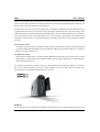
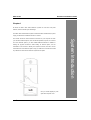
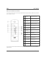
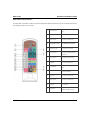
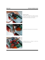
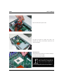
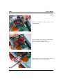
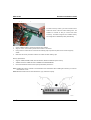
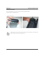
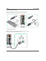
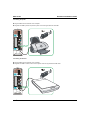
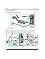
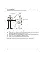
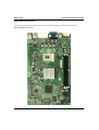
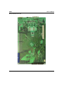
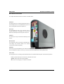
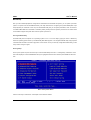
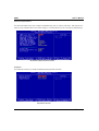
ZPCsp and ZPC64 Barebone User’s Manual Version 1.0 IWILL User’s Manual Contents: FCC Compliance Statement ………………………….…………………….……………….…….……………………………..........4 Disclaimer, Trademarks and Copyright ………………………….……….……………….………………………………...............5 Welcome ………………………………………………………….………………….……………….………………………...............6 About this manual ..……………………………………………………………………. …….……………….……………….............7 About this guide ….………………………………………………………………….……………….…………….………….............8 Unpacking …….……………………………………………………………….……………….…………….…………......................9 Chapter 1. System Introduction………………………….……………….……………………………………………...11 ZPCsp Front Panel Features …….………………………………………………….……………….…………………………….12 ZPCsp Rear Panel Features …….…………………………………………………………….……………….…………………….13 ZPC64 Front Panel Features …….………………………………………………….……………….…………………………….14 ZPC64 Rear Panel Features …….…………………………………………………………….……………….…………………….15 Internal Features …….……..…………………………………………………………………….……………….………………….16 Chapter 2. Assembling the System…………………………………………….……………….……………………17 Removing the cover …………………………………………………………………………………….……………….…………….18 Removing the front panel ..……………………………………………………………………………….……………….………….19 Open the chassis ………....……………………………………………………………………………….……………….………….20 Remove the gaskets…....……………………………………………………………………………….……………….………….21 Remove the cooling system…………………………………………………………………………….……………….………….22 Installing the processor ……………………………………………………………………………….……………….…….……….23 Installing system memory ……………………………………………………………………………….……………….………….25 Installing mini-PCI card …..……………………………………………………………………………….……………….………….26 Installing hard disk drives ……………………………………………………………………………….…………….……………27 Installing a PCI/ AGP expansion…..…………………………………………………………………….……………….…………28 Chapter 3. Positioning the System….…………………………...………………….…………………….……………33 Positioning the system unit …………………………………………………….……………….…………………………………….34 Connecting with a monitor …………………………………………………….……………….…………………………………….35 Connecting the keyboard and mouse..………………………………………………….……………….………………………….36 Connecting the Ethernet cable……….………………………………………………………….……………….………………….36 Connecting the printer……………..….………………………………………………………………….……………….………….37 Connecting the scanner……………….…………………………………….……………….……………………………………….37 Connecting the power cord..………….……………………………………………….……………….…………………………….38 Arranging your workspace……………………….………………………………………………….……………….……………..38 2 User’s Manual ZPC Series Hardware Installation Guide Chapter 4. Mainboard Information………………….……………….………………………………………………..39 Introduction……………………………………………………………………….……………….………………………………...…40 ZPCsp Motherboard photo 1………….………………………………………………….……………….……………………...…41 ZPCsp Motherboard photo 2………….………………………………………………….……………….……………………...…42 ZPC64 Motherboard photo 1……………………………………………………………….……………….……………………...…43 ZPC64 Motherboard photo 2……………………………………………………………….……………….……………………...…44 Rear External Connectors...……………………………………………………………...........…….……………….………….......45 Chapter 5. BIOS Setup………………...……….……………………………………………………………………………..47 Running the BIOS utility………………………….……………….………………………………………………………………..…48 General Configuration…………………………….……………….………………………………………………………………..…49 Smart Setting…………………………………………………….……………….……………………………………………………50 Advanced BIOS Features…………………………………………………….……………….…………………………………..…51 Advanced Chipset Features…………………………………………………………….……………….………………………..…52 Peripherals……………………………………………………………………………….………….……………….……………..….53 Power Management……………………………………………………………………………………….……………….…………54 PCI & PnP………………………………………………………………………………………………….……………….…………55 PC Health Status…………………………………………………………………………………………….………….…………..…55 Load Optimized Defaults………………………………………………………………………………….……………….……….…56 Save to CMOS and Exit……………………………………………………………………………….……………….…………..…56 Chapter 6. Drivers and Utilities……………………………………….……………….………………………………..57 Drivers and Utilities, Software….………………………………………………………….……………….…………………………58 Chapter 7. Specification…………………….…………………………….………………………………………………..59 Federal Communications Commission (FCC) statement User’s Manual 3 IWILL User’s Manual This equipment has been tested and found to comply with limits for a Class B digital device, pursuant to Part 15 of the FCC rules. These limits are designed to provide reasonable protection against harmful interference in residential installations. This equipment generates, uses, and can radiate radio frequency energy, and if not installed and used in accordance with the instructions, may cause harmful interference to radio communications. However, there is no guarantee that interference will not occur in a particular installation. If this equipment does cause interference to radio or television equipment reception, which can be determined by turning the equipment off and on, the user is encouraged to try to correct the interference by one or more of the following measures: Reorient or relocate the receiving antenna Move the equipment away from the receiver Plug the equipment into an outlet on a circuit different from that to which the receiver is connected Consult an experienced radio/television technician for additional suggestions This device complies with Part 15 of the FCC Rules. Operation is subjected to the following two conditions 1) this device may not cause harmful interference and 2) this device must accept any interference received, including interference that may cause undesired operation. Tested To Comply With FCC Standards FOR HOME OR OFFICE USE Disclaimer 4 User’s Manual ZPC Series Hardware Installation Guide The information in this document is subject to change without notice. The manufacturer makes no representations or warranties regarding the contents of this manual and specifically disclaims any implied warranties of merchantability or fitness for any particular purpose. Furthermore, the manufacturer reserves the right to revise this publication or make changes in the specifications of the product described within it at any time without notice and without obligation to notify any person of such revision. Trademarks Microsoft® and Windows® are registered trademarks of Microsoft® Corp. Intel® and Pentium® 4 are registered trademarks of Intel Corporation. Other product names used in this manual are the properties of their respective owners and are acknowledged. Copyright This publication, including all photographs, illustrations and software, is protected under international copyright laws, with all rights reserved. Neither this manual, nor any of the material contained herein, may be reproduced without the express written consent of the manufacturer. IWILL ©Copyright 2003 Welcome User’s Manual 5 IWILL User’s Manual Thank you for purchasing a ZPC™ series desktop PC. The ZPC™ features the IWILL® mainboard, power supply, cooling system and other quality components. It is ideal for the end-users to make a complete understanding about this model. The advanced users can also get help while studying this manual. The ZPC product line comes in two muscular configurations – Intel® 865G for Intel® Pentium® 4 and nVIDIA® nForce® 3 for AMD® Athlon® 64 CPUs. They all feature the high performance motherboard, high quality power supply, stylish anodized aluminum alloy enclosure designed and outstanding thermal solution as standard equipment. And of course they come with FireWire 400 ports, High Speed USB2.0, PCI or AGP expansion, optical S/PDIF, front headphone and microphone and built-in Ethernet - all as standard equipment. All models are WiFi-ready, and offer AccessPoint capability as a option. The Intel® based - ZPCsp The Intel® based- ZPCsp based on Intel® 865G chipset; supports Intel® Pentium® 4 processors, Expandable to 2GB dual channel 400MHz DDR with 800MHz system bus; IEEE1394; USB2.0; 6-Channel Audio; SPDIF In/Out; 10/100mbps Ethernet; and One PCI expansion slot. The AMD® based - ZPC64 ZPC64 based on nVidia® nForce 3 150 MCP; supports AMD® Athlon® 64 (Socket 754) processors with high-speed Hypertransport; 2 x 400MHz DDR memory, IEEE1394; USB2.0; 6-Channel Audio; SPDIF In/Out; 10/100mbps Ethernet; and One AGP 8X expansion slot. The information provided here is designed to help you to become familiar with the design and hardware in your system. With the user’s guide’s step-by-step instructions, chassis installation can never be easier. Read this manual, which provides updates and supplemental information about your computer. Audience This guide provides general information and installation instructions about the IWILL ZPC series Barebone System. This 6 User’s Manual ZPC Series Hardware Installation Guide guide is intended for experienced users and integrators with hardware knowledge of personal computers. How this guide is organized This document contains the following parts: 1. Chapter 1: System Introduction This chapter gives a general description of the IWILL book size barebone system. It includes introduction on the front and rear panel features, and the internal features. 2. Chapter 2: System Assembly This chapter tells how to install components into the barebone system through illustrated step-by-step instructions. 3. Chapter 3: Connection Peripherals This chapter detail steps in installing other Peripherals and components that can be included in the system. 4. Chapter 4: Mainboard Information This chapter describes proper mainboard placement for system safety and compliment space saving design. 5. Chapter 5: BIOS Setup This chapter tells how to change system settings through the BIOS Setup menus. It includes detailed descriptions of the BIOS parameters. 6. Chapter 6: Drivers and Utilities This chapter gives information about the ZPC Software, drivers, and utilities operation. 7. Chapter 7: Specification This chapter gives information about the ZPC detail specification. Illustrations used in this guide WARNING! Information to prevent injury to yourself when trying to complete a task. DANGER! Information to prevent damage to the components. IMPORTANT Information that you MUST follow to complete a task. NOTE Tips and additional information to aid in completing a task. Where to find more information Refer to the IWILL Websites for additional information and for product and software updates. User’s Manual 7 IWILL User’s Manual Unpacking ZPC Your ZPC may not be supplied with all of the accessories shown, depending on the system configuration you purchased. For details on the accessories supplied with your computer, see the specifications sheet in this manual. ZPCsp/ ZPC64 System unit External Power Adapter Power Cord IDE/ Power Cord for 2.5” HDD DVI to D-Sub Converter* 2.5” HDD Holder Drivers CD User’s Manual Quick Installation Guide Heatsink and cooling module have been assembled in the ZPC-ST already. Use 2.5” HDD holder to replace 3.5” HDD holder when you install longer AGP or PCI card If any of the above items is damaged or missing, contact your dealer immediately. DVI to D-Sub Converter only in ZPCsp version 8 User’s Manual ZPC Series Hardware Installation Guide Chapter 1 All about the IWILL ZPC series barebone system: the front and rear panel features, and the internal layout and design. The IWILL ZPC series barebone system includes the IWILL motherboard, a power supply, accessories and cables built into in a chassis you can attach external options, such as external speakers, a printer, or a scanner. For some external options, you must install additional software in addition to making the physical connection. When adding an external option, use the information in this section to identify the required connector, and then use the instructions that come with the option to help you make the connection and install any software or device drivers that are required for the option. System Introduction This section shows the various external connectors on your computer to which Use your hand/ fingertip to push open the front panel cover. User’s Manual 9 IWILL User’s Manual ZPCsp Front and Rear Panel Features: The front panel of ZPCsp features: a slim line bay for optical disk drive, Microphone, Earphone, SPDIF Out, 6-pin Firewire jacks, and USB2.0 connectors 1 Power switch Turns the computer on and off.. 2 Optical drive Slimline drive bay for optical drive 3 System Indicator 4 HDD access indicator 5 Universal Serial Bus 1 6 Universal Serial Bus 2 7 6-pin IEEE1394 8 System Reset Reset the System 9 SPDIF In Connection for SPDIF Input 10 Universal Serial Bus 3 11 Universal Serial Bus 4 12 headphone connector Connection for a headphone 13 microphone connector Connection for microphone The indicator light is amber when the computer is placed in Stand by mode Light is amber while reading and writing data from and to the hard disk. Connections for compatible high/ full/ low-speed USB devices. Connections for compatible high/ full/ low-speed USB devices. Connection for a compatible digital device. Connections for compatible high/ full/ low-speed USB devices. Connections for compatible high/ full/ low-speed USB devices. The front panel of your ZPC Computer enables access to drives, ports and jacks that enable you to connect compatible peripheral devices. 10 User’s Manual ZPC Series Hardware Installation Guide ZPCsp Rear Panel Features: The back panel of your ZPC-AP contains the ports for supplied and optional accessories. The icons on the back panel locate and identify the ports on your computer. Connection for the external power 1 Power connector 2 Keyboard port Connection for a PS/2 keyboard. 3 SPDIF Out Connection for SPDIF Output 4 S-video In jack Connection for an S-video cable 5 Empty PCI bracket Connections for PCI devices. 6 Monitor (DVI) port1 Connection for a DVI monitor. 7 Universal Serial Bus 5 8 Universal Serial Bus 6 9 Mouse port Connection for a PS/2 mouse. 10 Serial connector Connections for serial devices. 11 Microphone In jack Connection for a microphone 12 line-out connector supply. Connections for compatible high/ full/ low-speed USB devices. Connections for compatible high/ full/ low-speed USB devices. Connection for the supplied sub-woofer, or optional speakers or headphones. User’s Manual 13 line-in connector 14 6-pin IEEE1394 15 Ethernet port Connection for an audio device. Connection for a compatible digital device. Connection for a 10BASE-T/ 100BASE-TXBASE-TX Ethernet. 11 IWILL User’s Manual ZPC64 Front and Rear Panel Features: The front panel of ZPC64 features: a slim line bay for optical disk drive, Microphone, Earphone, SPDIF Out, 6-pin Firewire jacks, and USB2.0 connectors 1 Power switch Turns the computer on and off.. 2 Optical drive Slimline drive bay for optical drive 3 System Indicator 4 HDD access indicator 5 Universal Serial Bus 1 6 Universal Serial Bus 2 7 6-pin IEEE1394 8 System Reset Reset the System 9 SPDIF In Connection for SPDIF Input 10 Universal Serial Bus 3 11 Universal Serial Bus 4 12 headphone connector Connection for a headphone 13 microphone connector Connection for microphone The indicator light is amber when the computer is placed in Stand by mode Light is amber while reading and writing data from and to the hard disk. Connections for compatible high/ full/ low-speed USB devices. Connections for compatible high/ full/ low-speed USB devices. Connection for a compatible digital device. Connections for compatible high/ full/ low-speed USB devices. Connections for compatible high/ full/ low-speed USB devices. The front panel of your ZPC Computer enables access to drives, ports and jacks that enable you to connect compatible peripheral devices. 12 User’s Manual ZPC Series Hardware Installation Guide ZPC64 Rear Panel Features: The back panel of your ZPC64 contains the ports for supplied and optional accessories. The icons on the back panel locate and identify the ports on your computer. Connection for the external power 1 Power connector 2 Keyboard port Connection for a PS/2 keyboard. 3 Serial connector Connections for serial devices. 4 Empty AGP bracket For AGP 8X Card expansion 5 Microphone In jack Connection for a microphone 6 line-out connector supply. Connection for the supplied sub-woofer, or optional speakers or headphones. 7 line-in connector Connection for an audio device. 8 SPDIF Out Connection for SPDIF Output 9 6-pin IEEE1394 10 Universal Serial Bus 5 11 Mouse port Connection for a PS/2 mouse. 12 Serial connector Connections for serial devices. TV In Connector Connection for an mini-PCI TV Tunner (Optional) Card. (Optional) 13 14 User’s Manual Ethernet port Connection for a compatible digital device. Connections for compatible high/ full/ low-speed USB devices. Connection for a 10BASE-T/ 100BASE-TXBASE-TX Ethernet. 13 IWILL User’s Manual Internal Features The figure below shows the system from side. The standard components (CPU Heatsink, power supply…) are already installed. 14 User’s Manual ZPC Series Hardware Installation Guide Chapter 2 Step-by-step instructions on how to install basic components. This section outlines how to install and configure your ZPC. Refer to the following mainboard layout to help you to identify various jumpers, connectors, slots, and ports. Then follow these steps designed to guide you through a quick and correct Installation of your system. install other motherboards. Always turn the power off before you open the system or connect your computer to peripheral equipment. Otherwise, damage may occur to the integrated circuits in your computer. Electrostatic discharge (ESD) may damage HDDs and other components. Follow the procedures described here only at an ESD workstation. Ground yourself by maintaining continuous contact with an unpainted metal portion of the chassis while installation. User’s Manual Assembling the System IWILL has designed the ZPC for an IWILL motherboard only. It is not advisable to 15 IWILL User’s Manual Removing the cover 1. Disconnect all cables attached to the computer. This includes power cords, input/output (I/O) cables, and any other cables that are connected to the computer. 2. Remove the WLAN antenna on the top of the computer 3. Release the three screws at the rear of the left side cover 4. Separate the case and chassis cover: use your thumbs to pull it off, from the front to the back, then lift it off the chassis. Remove the base from chassis Remove the base Push down on the latch to release it. Release the screws Release the screws Remove the four screws on each end of the bottom. This frees the chassis cover. Disconnect the computer from its power source and from telecommunications links, networks, or modems before you open the unit or follow any procedures described in this section. 16 User’s Manual ZPC Series Hardware Installation Guide Remove the base from chassis Release the screw Remove this screw on the front panel. This frees the front cover. Push down on the latch Push down on the latch to release it. Press the latch to remove the front cover. Remove the front panel User’s Manual 17 IWILL User’s Manual Opening the chassis Opening the chassis Separate the case and chassis cover: Use your thumbs to pull it off, from the bottom to the top, then lift it off the chassis slightly. Gently detach the three front bezel hooks from the case front so that it may be removed. Push down on the latch Place the cable of antenna Place the cable of antenna inside the chassis in the appropriate position. Remove the front panel Remove the front bezel and set it aside. 18 User’s Manual ZPC Series Hardware Installation Guide Remove the gasket Release the gaskets Remove screws on gaskets from the bottom. This frees the gaskets. Gently detach the EMI gaskets from the chassis so that heatsink/pipe may be removed. Remove the CPU and system cooling system Gently remove the cooling system from the motherboard. Remove the four screws from CPU cooler To install the CPU, it is necessary to remove the pre-installed heatsink assembly. User’s Manual 19 IWILL User’s Manual Disconnect the power cord from the mainboard Disconnect the CPU fan power cable Start to install all the components The figure left shows the system from above. The standard CPU, Memory and SlimLine optical drive are need to be installed. Open the socket handle Lift Socket Lever Lift the load plate. By pressing the socket lever sideways, then lift it up to a 90°-100° angle. Do not touch the socket contacts Before installing or removing the processor, make sure AC power has been removed by unplugging the power cord from the computer; the standby power LED should not be lit. Failure to do so could damage the processor and the board. 20 User’s Manual ZPC Series Hardware Installation Guide Carefully insert the CPU into the socket until it fits in place. Make sure that the socket lever is lifted up to 90°~100° angle, otherwise the CPU does not fit in completely. Install the processor by carefully aligning the pins to the socket Carefully aligning the pins to the socket The CPU fits only in one correct orientation. DO NOT force the CPU into the socket to prevent bending the pins and damaging the CPU! When the CPU is in place, press it firmly on the socket while you push down the socket lever to secure the CPU. The lever clicks on the side tab to indicate that it is locked. Apply thermal cream Apply thermal cream on CPU Use the enclosed syringe and apply some thermal interface material to the top of the processor as shown in left photo. User’s Manual 21 IWILL User’s Manual Connect the Fan cable to the motherboard Connect the processor fan cable connector to the motherboard header. Secure four screws Align the heatsink and clip assembly with the retention mechanism and place it on the processor. Secure four screws to the retention mechanism. Align the gasket and place it Install the gasket by carefully aligning it to the bottom of heatsink. Turn the screw to the right to tighten it. 22 User’s Manual ZPC Series Hardware Installation Guide Installing System Memory To install a memory module, you insert a module into its socket and secure it with the socket retaining arms. The modules are notched so that you cannot insert them incorrectly. The BIOS recognizes the installed memory and configures the CMOS Setup Utility automatically. 1. Unlock a DIMM socket by pressing the retaining clips outward. 2. Align the “notch” on the memory module to the “break” on the socket. 3. Firmly insert the module into the socket until the retaining clips snap back into place and the module is properly seated. 4. Make sure the memory module is locked on the socket with both retaining clips. Memory Specifications 1. Supports 128MB, 256MB, 512MB, and 1GB modules, Maximum 2GB total system memory 2. 400MHz PC3200 or 333MHz PC2700 or 266MHz PC2100 DDR SDRAM 3. Dual Channel Modules and the same speed provide better performance. Note1: Installing two memory modules is recommended for this motherboard. When installing two modules, you must first fill the sockets 1 and 2. Note2: Modules should all be the same manufacture, type, model and capacity. User’s Manual 23 IWILL User’s Manual 1. Install the optical drive and Mini-PCI WLAN 2. Remove the CDROM holder 3. Install the mini-PCI card behind the CDROM 4. Connect the antenna cable. 5. Make sure the mini-PCI is well install 6. Slowly lift in the optical disk drive module. 24 User’s Manual ZPC Series Hardware Installation Guide 1. Remove the HDD holder 2. Carefully slip the HDD into the disk drive assembly. 3. Ensure that the 4 screw holes are properly aligned. 4. Connect power cable and connect it to the HDD. 5. Connect the IDE cable to the hard disk drive. Slowly lift in the hard disk drive module. User’s Manual 25 IWILL User’s Manual 1. Release the PCI/AGP bracket 2. Release the screw from the bottom. 3. Join the PCI/ AGP card with the bracket. 4. Secure the card and bracket with screw. 5. Install the card into the daughter card. 6. Install the card in the expansion slot 26 User’s Manual ZPC Series Hardware Installation Guide ZPCsp supports PCI expansion and dose not support AGP expansion. ZPC64 supports AGP expansion only. User’s Manual 27 IWILL User’s Manual Replace the cover After you have installed all the internal components and you have connected all the necessary cables, you are now ready to put the system back together. Follow these steps to re-assemble the system. 1. Replace the cover. Make sure the cover locks are properly clamped in place. 3. Gently join the another cover to the chassis so that it may be firmly fixed. 28 2. Gently join the hooks from the cover to the chassis so that it may be firmly fixed. 4. Make sure the four screw holes on the chassis cover are aligned to the holes on the case. Tighten the four screws. User’s Manual ZPC Series Hardware Installation Guide Replace the front panel After you have replaced the cover, you are now ready to put the front panel back together. Follow these steps to re-assemble the system. 1. Replace the front panel. Make sure the cover locks are 2. Tighten the screw. properly clamped in place. Carefully replace the front panel. Take caution when lifting in the drive assembly, you may damage the cables connected to the front panel and daughter board. User’s Manual 29 IWILL User’s Manual 30 User’s Manual ZPC Series Hardware Installation Guide Chapter 3 The small form factor design of the IWILL barebone system help to maximize work space and compliments your interior design. This chapter contains: Setting Up Your Computer Arranging your workspace User’s Manual Positioning the System Unit Positioning the System Unit 31 IWILL User’s Manual Positioning the System Unit The small form factor system is placed on a flat stable surface, like an office desk or computer table. Your computer may not be equipped with all of the hardware features described in the section. The location of the controls, ports, and jacks may vary from the illustrations shown. See the Specifications for your system's specific hardware configuration. 32 User’s Manual ZPC Series Hardware Installation Guide Setting Up Your Computer Connecting a Display (Monitor) Plug the display's cable into the monitor port. If necessary, plug the display's cable into the rear of the display. VGA→DVI If your monitor has a VGA connector and the optional video card is present, connect your monitor to the optional video card connector using the DVI adapter (included). DVI→DVI If your monitor has a DVI connector, connect your monitor to the optional video card connector. User’s Manual 33 IWILL User’s Manual Connecting the Keyboard and Mouse Plug the keyboard cable into the keyboard port on the back of the computer. Plug the mouse cable into the mouse port on the back of the computer. Connecting the Ethernet cable Plug the LAN cable into the LAN jack, located on the back panel of your computer. Plug the other end of the LAN cable into the wall jack. 34 User’s Manual ZPC Series Hardware Installation Guide Connecting the printer Plug the USB cord into the back of the computer. Plug both the USB to printer and printer’s power cords into a grounded AC wall outlet Connecting the Scanner Plug the USB cord into the back of the computer. Plug both the USB to scanner and scanner’s power cords into a grounded AC wall outlet User’s Manual 35 IWILL User’s Manual Connecting the Power Cords Plug the power adapter into the back of the computer. Connecting the Speakers Plug the cable attached to the back of the speaker into the (Red) Speaker jack on the back of the right speaker. Insert the yellow plug of the speaker power cable into the DC In jack (yellow) on the back of the right speaker. Insert the black plug of the speaker power cable into the DC Out jack located on the back panel of your computer. 36 User’s Manual ZPC Series Hardware Installation Guide Arranging your workspace Here are some guidelines to help you find better way to use your computer. . Viewing Distance Lower Back Support Seat Height Sitting in the same position for a long time can cause fatigue. A good chair can make a big difference. The backrest and seat should adjust independently and provide good support. The seat should have a curved front to relieve pressure on the thighs. Adjust the seat so that your thighs are parallel to the floor and your feet are either flat on the floor or on a footrest. When using the keyboard, keep your forearms parallel to the floor and your wrists in a neutral, comfortable position. Adjust the monitor so the top of the screen is at, or slightly below, eye level. Place the LCD monitor at a comfortable viewing distance, usually 50 to 60 cm. Also position other equipment you use regularly, such as the telephone or a mouse, within easy reach. User’s Manual 37 IWILL User’s Manual 38 User’s Manual ZPC Series Hardware Installation Guide Chapter 4 This chapter gives information about the IWILL motherboard that came with the system. This chapter includes the motherboard layout, jumper settings, and connector locations.. Mainboard Information User’s Manual 39 IWILL User’s Manual Introduction The ZPC mainboard is a high-performance motherboard that supports the Intel® Pentium® 4 processor with 478-pin socket or AMD® Athlon 64 CPU with 754-pin socket. This board has two DIMM memory sockets that accommodates dual channel 400 MHz DDR SDRAM and AGP or PCI for future expansion. ZPCsp The ZPCsp barebone Board adopts Intel® 865GV chipset to integrate all system control functions. Features of this system include support for: Intel® Pentium® 4 processor up to 3.4GHz 800/533 MHz system bus Up to 2GB DDR SDRAM for Dual Channel mode and up to 1GB DDR SDRAM One 32-bit PCI/33 MHz slot Onboard 10BASE-T/100BASE-TX Ethernet port Eight USB 2.0 external ports on rear and front panel Two IEEE1394 6-pin external ports on rear and front panel ZPC64 The ZPC64 barebone Board adopts nVidia nForce3 150 MCP to integrate all system control functions. Features of this system include support for: AMD® Athlon 64 processor 1600 MHz HyperTransport Bus Up to 2GB DDR SDRAM for Dual Channel mode and up to 1GB DDR SDRAM One AGP 8X slot Onboard 10BASE-T/100BASE-TX Ethernet port Six USB 2.0 external ports on rear and front panel Two IEEE1394 6-pin external ports on rear and front panel For a complete list of specifications, see detail specifications. 40 User’s Manual ZPC Series Hardware Installation Guide ZPCsp Motherboard Photos Here are two photos of ZPCsp motherboard from front and rear side. It helps you understand the whole system ZPCsp motherboard front view: User’s Manual 41 IWILL User’s Manual ZPCsp motherboard rear view: 42 User’s Manual ZPC Series Hardware Installation Guide ZPC64 Motherboard Photos Here are two photos of ZPC64 motherboard from front and rear side. It helps you understand the whole system ZPC64 motherboard front view: User’s Manual 43 IWILL User’s Manual ZPC64 motherboard rear view: 44 User’s Manual ZPC Series Hardware Installation Guide Rear External Connectors This chapter describes the external connection of the ZPC Series. PS/2 Ports The PS/2 ports are for a system keyboard and mouse or other tracking device. It is recommended that you do not plug or unplug devices when the system is on. Serial Port The COM Serial port has a 9-pin connector and can operate at speeds up to 115,200bps. Do not connect or disconnect a serial port when the system is turned on. VGA Port The VGA port is a 15-pin connector for attaching a VGA monitor. Ethernet Ports The LAN Ports is RJ-45 connectors for standard Cat 5 LAN cabling. The connectors attach to the onboard 10/100 LAN controllers respectively. USB Ports There are four high-speed USB 2.0 ports, USB 0 and USB 1, for connecting either USB 1.1 or 2.0 devices to the system. It does not matter if the system is on when you connect or disconnect USB devices. See the graphic below. Audio Jacks The audio jacks are for connecting external audio devices to the onboard audio subsystem. The three audio jacks are: Line In: provides audio input connector for an external audio source. Speaker: offers output to two stereo speakers. Mic: this jack is for plugging in a computer microphone. User’s Manual 45 IWILL User’s Manual The differentiate between ZPCsp and ZPC64 rear diagram: 46 User’s Manual ZPC Series Hardware Installation Guide Chapter 5 This chapter gives information about the ZPC Basic Input/Output System (BIOS) operation. BIOS Setup User’s Manual 47 IWILL User’s Manual BIOS Setup After you have installed peripherals, configured the motherboard and assembled the system, you can power up the ZPC system. The system uses the Award® BIOS utility. The setup instructions for configuring the system’s BIOS (Basic Input Output System) are contained on this chip. The Award BIOS Utility lets you set system parameters, which are stored in nonvolatile CMOS RAM. This information is retained by battery backup when the system is powered off. The values stored in the CMOS configures the system each time the system is powered on. Running the BIOS Utility The BIOS Utility does not depend on an operating system to run. You run the utility by typing the <Del> or Delete key before the operating system boots up. The BIOS Utility Main Menu appears. You navigate the BIOS Utility using keyboard commands that are listed on the lower right portion of each screen. Once you have fully configured the BIOS Utility you will rarely need to configure it again. Entering Setup Power up the system and press the <Del> key to enter the BIOS Setup main menu. n entering Setup, “Main Menu” is the first screen displayed. Use the UP/DOWN arrow keys to highlight the desired menu item and press ENTER to select this item. BIOS Setup Main Menu Use the arrow keys to select items. A description of each selection follows. 48 User’s Manual ZPC Series Hardware Installation Guide System Information System Information offers general system information, such as: BIOS information, CPU type and speed, parallel and serial port I/O addresses, IDE drive information, cache memory size, total memory size and memory in each slot. Use this information to verify if these components are installed and configured correctly. General Configuration The General Configuration screen lets you set time and date settings to suit your location. Set boot devices in the appropriate sequence. Power up options include Numlock, Primary VGA, and Boot Sector protection. You can set a User and Supervisor password after enabling the Password Required item. Forgot the Password? If you forget the password, you can clear the password by erasing the real time clock’s CMOS RAM. You can erase the CMOS RAM using the JCMOS1 jumper, see Appendix 1: Hardware Layout. After you have done so, hold down the <Del> key during boot up and enter BIOS setup to reenter user preferences. General Configuration Screen User’s Manual 49 IWILL User’s Manual Smart Setting Smart Setting allows users to enable CPU or memory options for over-clocking. 865 Turbojet option will enhance the system memory performance if enabled. Items under On-chip Serial ATA Setting allow users to enable/disable on-board Serial ATA function and set up the Serial ATA port mode if enabled. Smart Setting Screen 50 User’s Manual ZPC Series Hardware Installation Guide Advanced BIOS Features The Advanced BIOS Configuration sets CPU L1 and 2 cacheable, booting disk device settings, onboard LAN controller and BIOS write protection. Unless you fully understand the function of these settings, it is better to leave the default settings. Advanced BIOS Configuration Screen User’s Manual 51 IWILL User’s Manual Advanced Chipset Features The Advanced Chipset Setup screen configures the DRAM timing clock, the memory CAS latency, AGP aperture size... Unless you fully understand the function of these settings, it is recommended that you do not change the default settings. Advanced Chipset Setup Screen Advanced Chipset Feature Screen Peripherals The Peripherals screen lets you enable and disable onboard peripherals controllers. Peripherals Screen 52 User’s Manual ZPC Series Hardware Installation Guide OnChip IDE Device The OnChip IDE Device screens let you manually or automatically set up different IDE hard drives on two separate IDE channels – primary and secondary IDE channels. OnChip IDE Device Screen Onboard Device The Onboard Device screens let you manually or automatically set up onboard USB function, audio function and onboard Gigabit LAN function. Onboard Device Screen User’s Manual 53 IWILL User’s Manual SuperIO Device The SuperIO Device screen let set up onboard FDC function, Onboard Serial Port and Power On Setting. SuperIO Device Screen Power Management The Power Management screen lets you configure power management settings. Power Management Screen 54 User’s Manual ZPC Series Hardware Installation Guide PCI & PnP The PCI & PnP screen configures Plug and Play and other PCI bus settings. PCI & PnP Screen PC Health Status The PC Health Status screen shows information on the system’s voltages, fan rotations and temperatures. Hardware Monitor Screen User’s Manual 55 IWILL User’s Manual Load Optimized Defaults The Optimized Defaults Settings screen lets you reload the original manufacturer settings. The Restore Optimized Defaults lets the system start using the most reliable settings. Use this option when you can no longer boot the system due to changing, adding or removing hardware parts or peripherals. Restore Default Settings Screen Save to CMOS and Exit After making your selections in the Setup program, save your changes and exit BIOS Setup. Select Exit from the main menu and choose the appropriate option. 56 User’s Manual ZPC Series Hardware Installation Guide Chapter 6 This chapter gives information about the ZPC Software, drivers, and utilities operation. Drivers and Utilities User’s Manual 57 IWILL User’s Manual Drivers and Utilities The ZPC series comes bundled with a Power Installer CD-ROM disc that includes driver and utility software. This chapter describes installing and using this software. Running the Power Installer Disc The Power Installer CD-ROM install interface runs under Microsoft Windows 9X, NT 4.0, 2000, or XP. After inserting the disc into your CD-ROM drive the install interface loads automatically. Choose model ZPC from the selections. If it does not load, run the Power Installer directly from the disc by running Setup. Drivers and Utilities Screen This screen has five selections. Choose a selection to open its respective screen, which are described below. The User’s Manual selection opens the motherboard documentation. Choose Exit to leave this screen. Drivers Installation Screen Click Driver Installation in the Drivers and Utilities screen and the Driver Installation screen appears. Choose drivers in sequence to open their respective install programs. Select the installation guides to review installation information. When you are finished click Exit to leave this screen. Software Utility Screen Click Software Utility in the Drivers and Utilities screen and the Software Utility screen appears. To install the Adobe Acrobat Reader software, click on the item you wish to install and follow the instructions. Clicking on the Hardware Monitor Utility lets you install a program that gives access to information detected by the hardware monitor. Make Driver Screen Click Make Driver in the Drivers and Utilities screen and the Make Driver utility screen appears. This utility gives you a convenient way to make driver floppy disks. You can use this utility to make driver disks for the LAN driver. 58 User’s Manual ZPC Series Hardware Installation Guide Chapter 7 This chapter gives information about the ZPC detail specification. Specification User’s Manual 59 IWILL User’s Manual ZPCsp Specifications Processor Memory Chipset Graphics Ethernet USB 2.0 Firewire Drive Bay Expansion PSU Audio I/O ports Dimension Weight Supports Intel Pentium 4 CPU with 800MHz System Bus Supports Pentium 4 (Prescott Core) with maximum to 3.4GHz of speed DDR400/333 SDRAM Support; Unbuffer DDR SDRAM Total memory slots: two DIMM Maximum memory expansion: 2GB North Bridge: Intel 865GV; South Bridge: ICH5 VIA 6306 IEEE1394 Host Controller Realtek 8100B Fast Ethernet Controller Integrated Intel Extreme Graphics II Rapid Pixel Rendering Intel Dynamic Video Memory Technology DVI digital monitor outputs Realtek 8100B 100Mbps and 10Mbps Fast Ethernet operations Eight USB 2.0 Offer up to 480MB/s Four USB 2.0 external ports on the rear panel Four USB 2.0 external ports on the front panel IEEE1394-1394A compliant OHCI compatible programming interface Two IEEE1394 ports on the front and rear panel 100/200/400 Mbps data transfer rates One 3.5" drive bay for IDE HDD Or Two 2.5" drive bay for IDE HDDs * One internal drive bay for slim line optical driver One 32-bit, 33MHz PCI slot One Mini-PCI slot 220 Watt External Power Supply AC Input from 115~230V by 60-50Hz Fully support ATX specification Certification: RU; TUV; CE; FCC 6 Channel Audio utilizes the Realtek ALC655 codec Provides Superior Surrounding sound Line in/ Speaker/ Mic on rear panel Earphone/ Mic on front panel SPDIF optical audio In/Out USB 2.0: Eight (4 front and 4 rear) FireWire (IEEE 1394): Two (front and rear) Headphone: One (front) Microphone: Two (1 front and 1 rear) Line in: Two (one front, one rear) Speaker: One (rear) Serial: One (rear) PS/2 Keyboard: One (rear); PS/2 Mouse: One (rear) DVI: One (rear); S-Video: One (rear) Height: 245 mm Width: 75 mm Depth: 355 mm 6.22KG (Net weight, without CPU, RAM, HDD, CDROM) Certification: FCC class B; CE mark 89/336/ECC(EMV) 60 User’s Manual ZPC Series Hardware Installation Guide ZPC64 Specifications Supports AMD Athlon® 64 (Socket 754) with 1600 MHz Hyper Transport Supports Athlon 64 with maximum to 3400+ DDR400/333 SDRAM Support; Unbuffer DDR SDRAM Total memory slots: two DIMM Maximum memory expansion: 2GB nVIDIA nForce 3 150 MCP TI IEEE1394 Host Controller NV MAC + Realtek RTL8201BL PHY Ethernet nVidia MAC 10/100 Ethernet + Realtek RTL8110S (10/100 Mb) USB 2.0 Six USB 2.0 Offer up to 480MB/s Two USB 2.0 external ports on the rear panel Four USB 2.0 external ports on the front panel IEEE1394-1394A compliant OHCI compatible programming interface Two IEEE1394 ports on the front and rear panel 100/200/400 Mbps data transfer rates One 3.5" drive bay for IDE HDD Or Two 2.5" drive bay for IDE HDDs One internal drive bay for slim line optical driver One AGP 8X slot available One Mini-PCI slot 220 Watt External Power Supply AC Input from 115~230V by 60-50Hz Fully support ATX specification Certification: RU; TUV; CE; FCC 6 Channel Audio utilizes the Realtek ALC655 codec Provides Superior Surrounding sound Line in/ Speaker/ Mic on rear panel Earphone/ Mic on front panel SPDIF optical audio In/Out USB 2.0: Six (4 front and 2 rear) FireWire (IEEE 1394): Two (front and rear) Headphone: One (front) Microphone: Two (1 front and 1 rear) Line in: Two (one front, one rear) Speaker: One (rear) Serial: One (rear) PS/2 Keyboard: One (rear); PS/2 Mouse: One (rear) Height: 245 mm Width: 75 mm Depth: 355 mm 6.22KG (Net weight, without CPU, RAM, HDD, CDROM) Processor Memory Chipset Firewire Drive Bay Expansion PSU Audio I/O ports Dimension Weight Certification: FCC class B; CE mark 89/336/ECC(EMV) User’s Manual 61