1
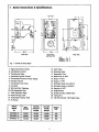
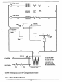
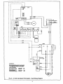
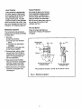
Vaillant ......
Installation and
Service Manual
GA100CS Series
Combination Gas
Fired Cast Iron
Boiler and Indirect
Water Heater
Table of Contents
1. Boiler Dimensions
Page
Number
2
& Specifications
2. Rules for Safe Installation
& Operation
3. Locating the Unit
4. Combustion Air Requirements
5. Vent Pipe Connections
6. System Piping Boiler
7. Gas Supply Piping
8. Electrical Wiring
9. Flame Roll-Out
10. Blocked Vent System
11, Checkout Procedures
12. Maintenance Requirements
3
3
3
4
5
5
7
7
®
9
9
10
PRICE $5.00
Vaillant
Vaillant Corp.
2607 River Road
Cinnaminson,
NJ 08077
(609) 786-2000
Fax (609) 786-8465
All of our appliances should be installed
by qualified fitters only, who will be
responsible for the observance of all
existing national and/or local installation
inStructionsand code regulations.
On installation please hand this pamphlet
to your customer.
o)
T--
"T
o
z
1. Boiler Dimensions
& Specifications
-IBI-[__._]A
---*
i°
.=
16
,-8
I*--
3o'/,"--÷1
t"------"
Side View
t
221/4" --'-*1
Front View
with Door Off
Rear View
ModM
"
GAt00CS-6
GAI00CS_
GAI00CS-10
A
10_/1"
11_11"
12_4"
B
5"
5"
6'
Fig. 1 - GA100 CS Series Boiler
1. High Limit Control (Tank)
2. Combination Control
15. Vent Valve
3. Transformer Relay
17. Expansion Tank
18. Boiler drain _' NPT
16. Diverting Valve
4. Intermittent Ignition Control
19. Return 1" NPT
5. Combination Pressure Temp. Gauge
6. Damper Actuator
7. Combination Gas Valve
20. Supply 1" NPT
21. Domestic Water Out (Hot) ¾"
8. Circulator
22. Domestic Water In (Cold) ¾"
23. Gas line ½" NPT
9. Wet Leg Drain Tappings
10. Pilot Inspection Door
24. Draft Diverter
11. Tank Inspection Plate
25. 30 PSI A.S.M.E. Relief Valve
12. Water Storage Tank
26. Tank Drain
13. Temperature Sensor Well
27.125
PSI A.S.M.E. T&P Relief Valve
14. Air Scoop
BOILER
" "
MODEL
NO.
GA100CS -6
"-
INPUT
BTU/HR
HEATING
I-B-R NET
CAPACITY
BTU/HR
RATING
B'I'U/HR
WBGHT
I.BS.
60,000
,50,000
43,000
340
GA100CS -8
80,000
67,000
58,000
360
GA100CS -10
100,000
85,000
74,000
390
]
2. Rules for Safe
Installation &
Operation
1. Read this manual and the
Owner's Manual carefully.
Failure to follow the rules for
safe operation and the instructions could cause a malfunction
of the boiler and result in death,
serious injury, and/or property
damage.
2. Check your local codes and
utility requirements before
installation. The installation
must be in accordance with
their directives.
3. Before servicing, allow boiler to
cool and always shut off any
electricity and gas to boiler
when working on it. This will
prevent any electrical shocks or
burns.
4. Never test for leaks with open
flame. Use soap suds to check
all connections. This will avoid
any possibility of fire or explosion.
5. Be certain boiler is equipped for
type of gas (natural or propane)
to be used. Over-firing will result
in premature failure of the boiler
sections and cause dangerous
operation.
6. Never vent this boiler into an
enclosed space. Always connect the boiler to the outside.
Never vent to another room or
inside a building.
7. Be sure there is adequate air
supply for complete combustion.
8. Follow a regular service and
maintenance schedule for efficient and safe operation.
WHEN YOUR BOILER ARRIVES
BE SURE TO SAVE AND REFER
TO INSTRUCTION .S_"First, inspect each item received for
visible damage or shortage. If any
parts are damaged, report this to
the freight company immediately,
and request them to cell and make
an inspection before you make any
installation. Have the Inspector
prepare a signed report. Send
Vaillant a copy of this report and we
will send replacements for the
damaged parts. But, we must have
the signed inspection report of the
freight company to prove their
liability.
Examine all packaging material
carefully for loose parts before
discarding.
ney opening must be high
enough to allow a '/," per ft.
upward slope in vent from unit
to chimney opening
4. Maintain clearances for fire safety
as well as servicing.
The room must have a total cubic
foot volume not less than 16
times that of the boiler.
Also, store all parts received where
they will not be lost or damaged.
5. Fresh air for combustion must be
available at the front of the boiler.
If you have had to unpack the boiler
outside, you may also have to disassemble it to carry it to the installation area. In this case, use the Parts
List drawings herein to guide you.
6. While this boiler may be installed
on combustible flooring, it must
not be installed on carpeting.
7. The installation must conform to
NOTE: The GA1 O0 CS Series of
boilers were evaluated by the
American Gas Association to certify
that they meet all of the safety criteria of ANSI standard 7_21.13a-Latest
Edition "Gas Fired Low Pressure
Steam and Hot Water Boilers." Safe
lighting and other performance criteria were met with the gas manifold
and control assembly provided on
the boiler when the boiler underwent
tests specified in this standard.
The following steps are all necessary for proper installation and safe
operation of the boiler.
1.
2.
3.
4.
5.
6.
7.
8.
Locating the boiler.
Fresh air for combustion.
Chimney & vent pipe connection.
System piping.
Gas supply piping.
Electrical wiring.
Check out and adjust.
Maintenance.
3, Locating the Unit
If unit is to be part of an existing
system, it is usually best to put it
where the old one was. If you plan
to change location, you will need
additional material as well as an
adequate base. The following rules
apply not only to replacement boilers, they also apply to new installations:
1. The unit must be level.
2. Use a raised base if floor can
become wet or damp.
3. The vent pipe connection should
be short. The center of the chim-
the requirements of the authority
having jurisdiction or, in the
absence of such requirements, to
the national Fuel Gas Code.
ANSI Z223.1-Latest Edition.
8. Where required by the authority
having jurisdiction, the installation
must conform to American
Society of Mechanical Engineers
Safety Code for Controls and
Safety Devices for Automatically
Fired Boilers, No. CSD-I.
Clearance from Combustible
Materials
The following minimum clearances
are required between boiler and
combustible construction:
Top ............................... 12 inches
Right Side ....................... 6 inches
Left Side ......................... 6 inches
Rear ................................ 6 inches
Flue Connector ............... 6 inches
Hot Water Pipe ................... 1 inch
Flue and stack must be at least 6"
from combustible surfaces.
If hot water pipe passes through
combustible floors, walls, or ceilings, clearance must be not less
than ½" capped with a non-combustible plate (see NFPA bulletin
89M, heating equipment clearance).
Servicing requirements may require
larger clearances than those
required for fire safety.
As the electrical and piping connections are at the rear of the unit,
there should be space to permit
access to the rear of the unit for service.
4. Combustion
Air
Requirements
WARNING
Be Sure to Provide Enough Fresh
Air for Combustion
You must provide for enough fresh
air to assure proper combustion.
The fire in the unit uses oxygen.
The air in a house contains only
enough oxygen to supply the bumer
for a short time. Outside air must
enter the house to replace that used
by the burner. Study the following
examples to determine your fresh
air requirements.
EXAMPLE 1: UNIT LOCATION IN
UNCONFINED SPACE
If your unit is in an open area in a
conventional house, the air that
leaks through the cracks around the
door and windows will usually be
adequate to provide air for combustion. The doors should not fit tightly.
Do not caulk the cracks around the
windows.
EXAMPLE 2: UNIT LOCATED IN A
HOUSE HAVING TIGHT CONSTRUCTION
If the house is of tight construction
with weathemtripped windows, not
enough outside air will enter for safe
combustion. Install a duct or pipe
from a point near the burner to a
ventilated attic or crawl space or the
outside where fresh air is freely
available. Vertical ducts should
have a net free area of 1 square
inch for each 4,000 BTU per hour
input of all gas appliances and for
each 2,000 BTUihr. if horizontal
ducts are used. Screen the openings to keep animals and birds from
entering. This is also required if the
boiler is installed near an exhaust
fan or clothes dryer.
Provisions for combustion and ventilation air in accordance with section
5.3, Air for CombustTon'_nd
Ventilation, of the National Fuel Gas
Cede, ANSI Z223.1-Latest Edition,
or applicable provisions of the local
building codes.
5. Vent Pipe
Connections
Check Your Chlmney
heating system. It must be clean,
the dght size, propedy con_ed
and in good condition. No boiler can
function properly with a bad chimney. If your chimney is just big
enough for your new boiler, it will
not have extra capacity for other
gas appliances.
so they will operate at maximum
speed. Do not operate a summer
exhaust fan.
When two or more appliances are
vented into the same chimney, the
cress-section area inside the chimney must be at least equal to the
area of the largest vent PLUS ½ the
area of each additional vent.
(e) Test for spillage at the draft
hoed relief opening after 5 minutes of main burner operation.
Use the flame of a match or can-
For example, if your boiler vent has
a diameter of 5 inches (area 19.6
square inches), the water heater
vent, a diameter of 4 inches (12.6
square inches), the minimum chimney area must be 19.6+ ½ of 12.6 or
25.9 square inches. They will
require a 6" diameter round chimney.
(f) After it has been determined
that each appliance remaining
connected to the common venting system propedy vents when
tested as outlined above, return
doors, windows, exhaust fans,
fireplace dampers and any other
gas burning appliance to their
previous conditions of use.
When removing a boiler from a
common venting system the venting
system is likely to be too large:for
proper venting of the remaining
appliances connected to it.
(g) Any improper operation of the
common venting system should
be corrected so the installation
conforms with the National Fuel
Gas Code, ANSI Z223.1-Latest
Edition. When resizing any portion of the common venting system, the common venting system
should be resized to approach
the minimum size as determined
using the appropriate tables in
Appendix G in the National Fuel
Gas Code, ANSI Z223.1-Latest
Edition
At the time of removal of an existing
boiler, the following steps shall be
followed with each appliance
remaining connected to the common venting system placed in operation, while the other appliances
remaining connected to the common venting system are not in operation.
(d) Place in operation the appliance being inspected. Follow the
lighting instructions. Adjust thermostat so appliance will operate
continuously.
dle, or smoke from a cigarette,
cigar or pipe.
(a) Seal any unused openings in
the common venting system.
Connect the Vent Pipe
(b) Visually inspect the venting
system for proper size and horizontal pitch and determine there
is no blockage or restriction, leakage, corrosion and other deficiencies which could cause an unsafe
condition.
NEVERINSTALLA
MANUALLY
OPERATED DAMPER IN THE
VENT PIPE OFANY GAS APPLIANCE.
(c) Insofar as is practical, close
all building doors and windows
and all doors between the space
in which the appliances remaining
connected to the common venting
system are located and other
spaces of the building. Turn on
clothes dryer and any appliance
not connected to the common
venting system. Turn on any
exhaust fans, such as range
hoods and bathroom exhausts,
This is a very important part of your
4
WARNING
1. Do not modify draft diverter furnished with the boiler.
2. Vent pipe must be same size as
outlet collar on draft diverter.
3. Slope pipe up from b_ler'to chimney not less than ¼" per foot.
4. Run pipe as directly as possible
with as few elbows as possible.
5. Do not connect to fireplace flue.
6. The sections of vent pipe should
be fastened with sheet metal screws
to make the piping rigid. Use
stovepipe wires to support the pipe
from above.
MinimumVentPipeClearance
ff theventpipemustgothrougha
crawlspace,doublewallventpipe
shouldbeused.Whereventpipe
passesthrougha combustible
wail
or partition,Usea ventilatedmetal
thimble.Thethimble should be 4
inches larger in diameter than the
vent pipe. If boiler is installed with a
single wall galvanized type vent, it
must have 6" clearance between its
surface and any combustible material. If Underwriters Laboratories listed type B (insulated vent pipe) is
used, clearance between it and
combustible material to be as listed.
In lieu of thimble protection, all combustible material in the wall shall be
cut away from the vent pipe a sufficient distance to provide the clearance required from vent pipe to
combustible material. Any material
used to close up such opening shall
be non-combustible.
For boilers for connection to gas
vents or chimneys, vent installations
shall be in accordance with Part 7,
Venting of Equipment, of the
National Fuel Gas Cede, ANSI
Z223.1--Latest Edition, or applicable provisions of the local building
codes.
must not be threaded.
Connect supply and return lines to
boiler. The connections may require
certain additional fittings and parts
as shown on Fig. 2.
If you are replacing an old boiler
with this new one, possibly all you
will need to do is to connect the
existing piping to your boiler.
If you are installing an entire new
heating system, first install all of
your radiation units (panels, radiators, or cabinets) and the supply
and return mains--then make the
connection to the boiler.
When connecting the cold water
supply to the water valve, make
sure that a clean water supply is
available. When the water supply is
from a well or a pump, a sand
strainer should be installed at the
pump.
When boiler is used in connection
with refrigeration systems, it shall be
installed so that the chilled water is
piped in parallel with the heating
boiler with appropriate valves to prevent the chilled water from entering
the heating system boiler.
The GA100 Series of boilers are fitted with an integral vent damper
which is operated by an actuator
mounted on the front panel (See
Fig. 1).
The boiler piping system of a hot
water heating boiler connected to
heating coils located in air handling
units where they may be exposed to
refrigerated air circulation must be
equipped with flow control valves or
other automatic means to prevent
gravity circulation of the boiler water
during the cooling cycle.
The stack damper should be
checked for alignment and freedom
of operation prior to installation and
during subsequent routine service.
NOTE: A hot water boiler installed
above radiation level must be provided with a low water cutoff device
at the time of boiler Installation.
Automatic Vent Damper
6. System Piping
Boiler
Place the boiler in a selected location (as near chimne_yy
as possible).
Your boiler is shipped assembled.
You need only to install a ¾" relief
valve drain line. Run a pipe from the
relief valve outlet to an open drain,
tub or sink, or other suitable
drainage point not subject to freezing. Failure to do so may cause
water damage or injury should the
relief valve open. Pipe must be
_'ame size as outlet and open end
It is recommended that the boiler be
installed with gate valves on the
supply and return lines so that it
may be removed for service without
draining the entire system. The gate
valve on the supply pipe must not
be located between the boiler and
the relief valve or expansion tank.
Water Heater
The relief valve and drain valve for
the flow and for the hot water tank
(Fig. 2) are packed in separate
boxes and mount directly to the flow
and return.
If the selected temperature at the
temperature control (Fig. 1, No. 1) is
in excess of 125°F a mixing valve
should be installed to minimize the
danger of scalding.
7. Gas Supply Piping
INSTALL GAS PIPING AS OUTLINED IN THE AMERICAN
NA't'IONAL STANDARD ANSI
Z223.1-1984-- NATIONAL GAS
FUEL CODE FOR U.S.A. INSTALLATIONS
The gas pipe to your boiler should
run direct from the gas meter (or
propane regulator). It should supply
only the boiler. It must be the correct size for the length of the run
and the boiler rating. See Fig. 3 for
the proper size. Be sure your gas
line complies with local codes and
the gas company requirements.
Connecting the Gas Piping
Refer to Fig. 1 for the general layout
at the boiler. It shows the basic fittings you will need. The gas line
enters the boiler from the back. The
following rules apply:
1. Use new, properly cleaned
black iron piping and fittings,
free from chips.
2. Apply good quality pipe dope to
pipe only, leaving 2 end threads
bare.
3. Install a sediment trap to trap
dirt and moisture before it can
enter the boiler.
4. Install a manual shut-off valve in
vertical pipe about 5 feet above,
floor (not supplied by Vaillant).
5. Tighten all joints securely.
6. Propane gas connections
should only be made by a
licensed propane installer.
7. The boiler and its individual
shut-off valve must be disconnected from the gas supply piping system during any.pressure
testing of that system at test
pressures in excess of ½ psig.
8. The boiler must be isolated from
the gas supply piping system by
closing its individual manual
shutoff valve during any pressure testing of the gas supply
piping system at test pressure
equal to or tess than ½psig
(3.5KPa).
ZONE VALVE
IIIIIII1
HEATING
cl_curr
CIRCUITS
VALVES
* ZONE VALVE
©
GATE
DRAIN
VALVES
III1[1111
__
t
AIR SCOOP
ASME PRESS.
vE_,
_-_
_
REUEF VALVE
I
BOILER
t
VALVE
EXPANSION
TANK
'._ to.,_.
_.
t
t
ASMET&P
REUEFVALVE
TO FAUCETS
& SHOWERS
DOMESTIC
COLD WATER
. -
* NOTE:- Zone valves
should be located in
the supply side of the
heating circuit as close
as is possible to the
three way valve. This
will minimize the chance
"-_
..vALVE
DR/UN
VALVE
of waterhammePoocuring.
STORAGE TANK
CAUTION: When storage tank is above 125°F a mixing valve should be installed
to minimize the chance of scalding.
F,ig. 2 - Typical Piping Arrangements
Checking the Gas Piping
Upon completion of piping, chock
right away for gas leaks. Open the
manual shut-off valve. Test for leaks
by applying soap suds (or a liquid
detergent) to each joint. Bubbles
foaming indicate a leak.
CORRECT EVEN THE SMALLEST
LEAK AT ONCE.
WARNING
NEVER USE A MATCH OR OPEN
FLAME TO CHECK FOR LEAKS.
NATURAL GAS
LENGTH
OF PiPE
-FT.
PiPE CAPACITY
CUBIC FEET/HOUR
before turning boiler on. See Figs. 4
&5.
8. Electrical
Wiring
Install Your Thermostat.
The thermostat location has an
important effect on the operation of
your boiler system. BE SURE TO
FOLLOW THE INSTRUCTIONS
INCLUDED WITH YOUR THERMOSTAT.
Locate the thermostat about five
feet above the floor on an inside
wall. It may be mounted vertically on
the wall or on a vertically mounted
outlet box. It should sense average
room temperature, so avoid the following:
_"
¾"
1"
1_"
20
74
150
280
580
40
50
100
195
400
Dead Spots:
60
40
84
155
320
1. Behind doors
2. Corners and alcoves
80
34
72
135
275
Hot Spots:
Fig. 3 - Gas Pipe Capacities
MODEL GA100 CS
-60
-80
-100
Sea level to 2,000 ft.
38
42
38
2,000 to 5,000 ft.
40
43
41
5,000 to 7,000 ft.
41
44
42
7,000 to 9,000 ft.
42
46
43
9,000 to 10,000 ft.
43
47
44
Elevation
Fig. 4 - Orifice Size for Natural Gas
MODEL GA100 CS
120-Volt Wiring
All new and replacement wiring
must be U.L. listed and 14-gauge
size (minimum). Install wire in
approved conduit. All terminals and
splices must be in a listed covered
box.
If an external electrical source is utilized, the boiler, when installed,
must be electrically ground in accordance with the requirements of the
authority having jurisdiction or, in
the absence of such requirements,
with the National Electrical Code,
ANSI/NFPA No. 70-Latest Edition.
24-Volt (Low Voltage) Wiring
Use listed low-voltage cable. All
junctions must be clean, joined firmly, and suitably covered with electrical tape or approved wire connectors.
9. Flame Roll Out
1.
2.
3.
4.
Concealed pipes
Fireplaces
TV sets
Radios
5. Lamps
6. Direct sunlight
7. Kitchens
Cold Spots:
1.
2.
3.
4.
Concealed piping or ducts
Stairwell drafts
Door drafts
Unheated rooms on other side
of wall
-60
-80
-100
Sea level to 2,000 ft.
52
53
52
Control Wiring Diagrams
2,000 to 5,000 ft.
53
55
53
Field Wiring and Wire Replacement
5,000 to 7,000 ft.
53
55
53
7,000 to 9,000 ft.
55
56
54
9,000 to 10,000 ft.
55
56
54
in the following wiring diagrams
dashed lines ....
represent factory wiring 24V; dashed lines
• • • represent field wiring 24V;
solid lines -represent factory
wiring 120V; solid lines _
represent field wiring 120V.
The GA100 CS Series is equipped
with a Flame Roll-Out Safety ShutOff System. The system is designed
to shut off the boiler if a blockage
occurs in the heat exchanger that
causes flames to roll-out the bottom
of the burner tray. Temperature activated switch is located on a bracket
next to the pilot or ignitor on the
underside of the burner tray.
When corrective action has been
taken to eliminate the restriction
the pre-set switch has to be
replaced with a Vaillant supplied
replacement.
Elevation
Fig. 5 - Orifice Sizefor Propane (LPG)
Orifice Sizing
All Vaillant GA100 CS series units
are factory equipped with orifices
sized for installation at elevations
ranging from sea level up to 2,000
feet. For higher elevations, smaller
orifices are required to assure safe
operation.
Order the proper orifices
e
from your supplier and install them
Field wiring, whether for a new
installation or to replace damaged
field or factory installed widng, must
be the type listed below, and must
be installed in accordance with the
National Electric Code and all other
codes and standards covering the
boiler installation.
10. Blocked Vent
System
The GA100 CS Series is equipped
with a =BlockedVent Shut-Off
System'. This system relies on a
temperature sensitive-6witch located
on the side of the draft hood. If the
vent pipe or chimney should
become obstructed to the point of
not completely evacuating the flue
gases, the switch will break and
close down the unit.
When the vent or chimney restriction has been removed, the switch
can be reset.
I"
I
I
I
I
!
i
I
.......... °
L8148E
©
®
eI.ACK
WHITE
#
BLUE
BLUE
fill
$8_0
OUT I
i_
llll
I I i LREO=_
I I L_ WHITE
I
MV PV PV GiNID GND 24V -W
24v
TH
I
I
I
I
I
GREEN
I
GOLD
L ....
I
I
DAMP
IGN
glv-1
!
!
I
I
I
_
BLUE
WHITE
_E
I
I
.......
.e.._m__K.
__
! I
t_ -.
__R___.
t
Y
•
I
J
I
I
v
•
•
_
i
•
•
I
l
•
I
', ••
I
I
•
e
•
!
C°l
I
i
-_l
I
I
f
I=""='"_
_'-%1 _'"
f ,,,-,'r,'_l I
\ ..... 11
..,, ..T_/
"n4REEWAY L
_St.ACK
I-r.. I,,'.._
Fig. 6 - 24 Volt Intermittent
-[
',
IMPORTANT:
•
•
I
'
--
......
-_20V
-120V
"-f-
[
1I
I
,
-_
!
,
, R_
Fmo,y W_)
FieklW_ng
B
•
•
r-e--- YELLO_
;"_L
S_d Lira Rm_er_
AAAAAAAA'*AAAAA ;'_'* *.
I
I
II
,-I
-_V
••
c
[
F,_Wy W_V_
iI
I_,;_
I---
I
I
Ik._,i_d,,_
I
I .....
Pilot System - Field Wiring Diagram
8
"
'_'
•,
•
•,
__,
•
•;
"b-
,
_,
-_- ....
•
''
,
••
•
', ",
•
•
•
iIEL°
IT
_-I
11. Checkout
Procedures
Test for Any Gas Leaks
Inspect carefully all gas connections
for gas leaks before lighting bumer.
Do not check for leaks with an
open flame.
Test for leaks with a soap solution
made of 2 tablespoons of flake,
granular, or liquid soap mixed well
with _ cup of warm water and
spread generously on connection in
question, using a brush or cloth.
For Your Safety Read
Before Operating
WARNING
IF YOU DO NOT FOLLOW
THESE INSTRUCTIONS EXACTLY, A FIRE OR EXPLOSION MAY
RESULT CAUSING PROPERTY
DAMAGE, PERSONAL INJURY
OR LOSS OF LIFE.
A. This appliance is equipped with
an ignition device which automatically lights the burners. Do not try
to light the pilot by hand.
B. Before operating smell all around
the appliance area for gas. Be
sure to smell next to the floor
because some gas is heavier
than air and will settle on the
floor.
WHAT TO DO IF YOU SMELL GAS
• Do not try to light any appliance.
• Do not touch any electric switch;
do not use any phone in your
building.
• Immediately call your gas supplier from a neighbor's phone,
follow the gas supplier's instructions.
• If you cannot.r.ea_,byour gas
supplier, call the Fire
Department.
C. Use only your hand to push in or
turn the gas control knob, never
use tools. If the knob will not push
in or turn by hand, don't try to
repair it, call a qualified service
technician. Force or attempted
repair may result in a fire or
explosion.
Operating Instructions
1. STOP! READ THE SAFETY
INFORMATION.
ELECTRONIC IGNITION
II_'T
"_
OUTLET
GROUND
TERM_kt_L
2. Set room thermostat to lowest
B
temperature.
VR8440
3. Turn off electric power.
4. Turn gas cock knob clockwise
and turn to OFF. Wait five minutes, then turn knob to latch
position at ON.
ELECTRONIC IGNmON
TERMINAL
5. Turn on electric switch. Burner
should turn on when thermostat is
set above room temperature.
INLET
_
_CO_I
ROUND
L g-J_B
Reset Ignition System
VR8204A
1. Turn the thermostat to the low
end of its temperature range.
2. Turn the electric switch to the
HOT SURFACE IGNmON
OFF position.
3. Wait 5 minutes, then turn the
system switch to ON position set
the thermostat at least 4°F
(2.2°C) above room temperature.
The boiler should start. If the
above steps do not start the pilot
and main burner, call your gas
appliance service technician, do
not attempt to light manually.
To Turn Off Gas To Appliance
1. Set the thermostat to lowest
setting.
2. To shut off burner manually, turn
gas cock knob clockwise F'_
and turn to OFF position.
3. Turn off electric switch.
Adjustment of Gas Input--Natural
Gas
To check for proper flow of gas into
combustion chamber, determine the
BTU/hr. input from the instruction
plate on the jacket. Divide this input
by the BTU per cubic foot of available gas to get the required number
of cubic feet of gas per hour.
GAS..>.
INLET
- SIEP
FEATURE
GAS CONTROL
KNOB
36E03
Determine flow of gas through the
gas meter for 2 minutes and multiply
by 30 to get the hourly flow rate.
Turn off all other gas equipment
connected to meter when making
this test.
Manifold pressure should be set to
about 4" W.C. for natural gas. Small
variations in gas flow may be made
by means of the gas pressure regulator adjustment. However, the final
manifold pressure setting should not
vary more than plus oT mlhus 0.3"
from the 4" valve. Any necessary
major changes in the flow should be
made by changing the size of the
burner orifice.
Safety Check of Controls
Main Burner
After boiler has been hooked up and
is ready for operation, a few simple
checks should be made to be sure
all controls are functioning properly.
The main burner flame can be
observed through the inspection
door (Fig. 7). The flame should be
translucent and blue in color. The
1. Thermostat--Turn thermostat to
highest setting. This should turn
on the main burner. Adjust heat
anticipator to proper current draw.
presence of any yellow streaking
would indicate the presence of dust
or lack of primary air. A vacuum
cleaning of the burner tray and combustion area is indicated.
2. Thermocouple--The pilot lights
the main burner on demand and
provides a safety feature through
either a single couple thermocoupie or multiple couple thermocoupie which is placed in the pilot
flame. These thermocouples generate a small amount of electricity
which permits the valve to open
only when the pilot is burning. To
check the thermocouple for safe
operation, ignite the main burner,
then disconnect the thermocouple
lead. The main burner should
shut off.
3. Limit--The limit turns off the
burner when the boiler water temperature reaches the temperature
setting of the limit. To check this,
set the limit at a lowest setting
and let the burner run until the
limit turns it off. Raise temperature setting of limit. This should
turn on burner.
Relief Valve
You have a safety relief valve on
your boiler. It will automatically open
at 30 psig pressure. This will relieve
the strain on the boiler and system.
Run a pipe from the relief valve outlet (pipe must be same size as outlet and open end must not be
threaded) to an open drain, tub or
sink, or other suitable drainage point
not subject to freezing. Failure to do
so may cause water ci_mage or
injury should Relief Valve release.
DOOR
_
Fkj.7
Checks for Electronic Ignition
The probe lead connections to
sensing probe and control terminal
must be secure. Electrodes should
have a spark gap of '/a". If the pilot
burner does not ignite, check to see
that all connections are proper.
Observe presence of spark. If spark
is not present, determine if power is
available to the control. The ignition
control should be replaced if, with
power applied and spark gap properly set at _", sparking does not
occur. If pilot gas does not light
even though a spark is present, gas
is not available at the pilot burner or
the gas pressure is too low or high.
If pilot ignites, but burner does not,
check probe lead connections to the
sensing probe and control. Do not
attempt to field repair the control.
Replace defective controls.
10
12. Maintenance
Requirements
CLEANING MUST INCLUDE PERIODIC EXAMINATION OF VENTING
SYSTEMS. ALL FLUE GAS PASSAGEWAYS FROM BOILER TO
CHIMNEY AND THE CHIMNEY
ITSELF SHOULD BE INSPECTED
AND CLEANED IF NECESSARY.
THIS SHOULD BE PERFORMED
AT LEAST ONCE A YEAR, PRIOR
TO THE STARTING OF THE
HEATING SEASON.
1. Brush entire surface of all flues
using a long handled wire brush.
Remove all soot, rust and scale
found. Inspect with a flashlight to
see that all flueways are completely open. Remove soot and
dirt from bottom of boiler.
2. Inspect the flue cover, draft
diverter, and smokepipe and
replace unserviceable parts,
clean all soot, rust or scale from
these parts and from chimney.
Clean the burners; use a soap
solution if necessary.
CAUTION: If it becomes necessary
to remove the draft diverter, it must
be rasealed to the casting using
new sealant to be sure no fumes
can escape.
3. Reassemble all parts and start
the boiler following the installation
instructions. Carefully inspect fire
above each burner for a stable
and blue flame. Carbon monoxide
poisoning can be caused by yellowish unstable (wavy) flame.
;urnerCleaning
urnersshouldbeinspected
after
achboilercleaning.
Slots(ports)
anbebrushedfreeofdirtandlint
,ith a stiff bristle brush. Do not
amage metal at ports. The pilot
nd thermocouple or pilot generator
should be brushed free of dirt. Take
care not to damage pilot, bend it out
of position, or to plug pilot gas port.
Freeze Protection
If the boiler is taken out of service
during potentially freezing weather,
always DRAIN IT COMPLETELY
since any water left in the boiler or
pipes can freeze and cause damage. Be sure to open drain cocks on
the wet legs of the left and right
castings, see Fig. 1.
Pilot and Burner
Maintained Inspection
The homeowner and service personnel must, at all times, be alerted
for these items:
Check for proper pilot flame as
explained in "Checkout Procedures'
on page 9.
1. Gas odor.
a) Open the windows.
b) Do not touch any electrical
switch.
c) Extinguish any open flame,
if possible.
d) Shut off the main gas valve.
e) Call the gas supplier.
Burner Ports
and Slots
4- 3/..
-..-,/..
±'/."
2. Excessive heat, odors, smoke,
unusual noise. Shut off gas to
all appliances and call gas supplier or Fire Department and
service organization.
3. Keep area around the boiler
clean and free from combustible
materials, gasoline and other
flammable vapors and liquids.
4. Make allowances and maintain
free flow of combustion and
ventilating air.
PilotBracket Mounted
on Burner Panel
Pilot and Burner Assembly
Fig. 9 - Electronic Ignition
11
ForUse with Natural
& Propane Gas
- GA100 -60 Thru GA100 -100 E.I.
Vaillant
Vaillant Corp.
2605-07 River Road
Cinnaminson, NJ 08077
(609) 786-2000
m
Booklet No.:2180-0113