1
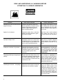
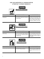
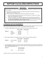
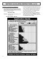
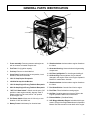
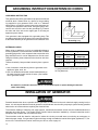
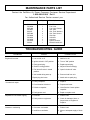
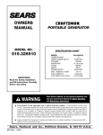
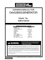
OWNERS MANUAL FOR
DeVILBISS GENERATOR
Model No.
GBV4600
SPECIFICATION CHART
MODEL
HORSE POWER
RATED/SURGE WATTS
VOLTAGE
AMPERAGE
PHASE
HERTZ
ENGINE SPEED
MAX. AMBIENT TEMP.
FUEL CAPACITY
RUN TIME @ 50%/100%
GBV4600
9
4600/5750
120/240
38.3A/19.2A
SINGLE
60 Hz
3600 RPM
104° F
6 GALLON
13.3/6.5 HR
• This product is not equipped with a spark arresting muffler.
If the product will be used around flammable
materials, or on land covered with materials such as agricultural crops, forest, brush, grass, or other similar
items, then an approved spark arrester must be installed and is legally required in the state of California. It is a
violation of California statutes section 130050 and/or sections 4442 and 4443 of the California Public Resources
Code, unless the engine is equipped with a spark arrestor, as defined in section 4442, and maintained in effective
working order. Spark arresters are also required on some U. S. Forest service land and may also be legally
required under other statutes and ordinances.
• Engine exhaust from this product contains chemicals known, in certain quantities, to cause cancer, birth defects or
other reproductive harm.
MGP-4600 6/13/95
DeVilbiss Air Power Company
•
213 Industrial Drive
•
Jackson, TN
38301-9615
TABLE OF CONTENTS
PAGE
WARRANTY STATEMENT ...................................................... 3
SAFETY GUIDELINES AND INSTRUCTIONS ......................... 4-8
WATTAGE CALCULATING INSTRUCTIONS ........................... 9-10
GENERAL PARTS IDENTIFICATION ...................................... 11
GROUNDING INSTRUCTIONS/EXTENSION CORDS ............. 12
INSTALLATION OF A GENERATOR ....................................... 12
OPERATING INSTRUCTIONS ................................................. 13
MAINTENANCE SCHEDULE ................................................. 13
MAINTENANCE PARTS LIST ................................................. 14
TROUBLE SHOOTING GUIDE ................................................ 14
INSTALLATION OF BATTERY ................................................. 15
In the unlikely event you should have a problem with this
product or if you are missing any parts, it is not necessary to
return it to the store where you purchased it. Simply call our
toll-free number and talk with our Service Representative.
OUR OFFICE HOURS ARE FROM
8:00 a.m. to 4:30 p.m. (CST)
MONDAY THROUGH FRIDAY
CALL TOLL-FREE 1-800-888-2468, EXT. 2
2
LIMITED WARRANTY
ONE YEAR FROM DATE OF PURCHASE
All merchandise manufactured by DeVilbiss Air Power Company is warranted to be free of defects in workmanship
and material which occur during the first year from the date of purchase by the original purchaser (initial user).
Products covered under this warranty include: air compressors, *air tools, accessories, service parts, pressure
washers, and generators used in consumer applications (i.e., personal residential household usage only).
Air compressors, *air tools, accessories, service parts, pressure washers, and generators used in commercial
applications (income producing) are covered by a 90 day warranty.
DeVilbiss Air Power will repair or replace, at DeVilbiss's option, products or components which have failed within the
warranty period. Repair or replacement, and service calls on 60 and 80 gallon air compressors, will be handled by
Authorized Warranty Service Centers and will be scheduled and serviced according to the normal work flow and
business hours at the service center location, and depending on the availability of replacement parts.
All decisions of DeVilbiss Air Power Company with regard to this policy shall be final.
This warranty gives you specific legal rights, and you may also have other rights which vary from state to state.
RESPONSIBILITY OF ORIGINAL PURCHASER (Initial User):
o
o
o
o
o
Retain original cash register sales receipt as proof of purchase for warranty work.
Use reasonable care in the operation and maintenance of the product as described in the Owners Manual(s).
Deliver or ship the product to the nearest DeVilbiss Air Power Authorized Warranty Service Center.
Freight costs, if any, must be paid by the purchaser.
Air compressors with 60 and 80 gallon tanks only will be inspected at the site of installation. Contact the nearest
Authorized Warranty Service Center, that provides on-site service calls, for service call arrangement.
If the purchaser does not receive satisfactory results from the Authorized Warranty Service Center, the purchaser
should contact DeVilbiss Air Power Company.
THIS WARRANTY DOES NOT COVER:
o
o
o
o
o
o
o
o
o
Merchandise sold as reconditioned, floor models and/or display models. Any damaged or incomplete equipment
sold "as is".
Merchandise used as "rental" equipment.
Merchandise that has become inoperative because of ordinary wear, misuse, freeze damage, use of improper
chemicals, negligence, accident, improper and/or unauthorized repair or alterations including failure to operate
the product in accordance with the instructions provided in the Owners Manual (s) supplied with the product.
*Air Tools: O-Rings and driver blades are considered ordinary wear parts, therefore, they are warranted for a
period of 45 days from the date of purchase.
An air compressor that pumps air more than 50% during a one hour period is considered misuse because
the air compressor is undersized for the required air demand. Maximum compressor pumping time per hour is
30 minutes.
Merchandise sold by DeVilbiss Air Power which has been manufactured by and identified as the product of
another company. The product manufacturer's warranty will apply.
Repair and transportation costs of merchandise determined not to be defective.
Cost associated with assembly, required oil, adjustments or other installation and start-up cost.
ANY INCIDENTAL, INDIRECT OR CONSEQUENTIAL LOSS, DAMAGE, OR EXPENSE THAT MAY RESULT FROM
ANY DEFECT, FAILURE OR MALFUNCTION OF THE PRODUCT. Some states do not allow the exclusion or limitation
of incidental or consequential damages, so the above limitation or exclusion may not apply to you.
IMPLIED WARRANTIES, INCLUDING THOSE OF MERCHANTABILITY AND FITNESS FOR A PARTICULAR
PURPOSE, ARE LIMITED TO ONE YEAR FROM THE DATE OF ORIGINAL PURCHASE. Some states do not allow
limitations on how long an implied warranty lasts, so the above limitations may not apply to you.
213 Industrial Drive • Jackson, TN 38301-9615 • Telephone: 1-800-888-2468 , Ext. 2 • FAX: 1-800-888-9036
Form: SP-100-E - 4/19/95
3
SAFETY GUIDELINES - DEFINITIONS
This manual contains information
that is important for you to know
and understand. This information
relates to protecting YOUR
SAFETY and PREVENTING EQUIPMENT PROBLEMS. To help you
recognize this information, we
use symbols to the right. Please
read the manual and pay attention to these sections.
URGENT SAFETY INFORMATION - A HAZARD
THAT WILL CAUSE SERIOUS INJURY OR LOSS
OF LIFE
Information for preventing damage to
equipment.
IMPORTANT SAFETY INFORMATION - A HAZARD
THAT MIGHT CAUSE SERIOUS INJURY OR LOSS
OF LIFE.
Information that you should pay special
attention to.
IMPORTANT SAFETY INSTUCTIONS
• SAVE THESE INSTRUCTIONS •
When using this product basic precautions should always be followed
including the following:
RISK OF ELECTROCUTION AND FIRE
HAZARD
Attempting to connect generator directly
to the electrical system of any building
structure.
WHAT COULD HAPPEN
Back feeding electricity through a
building’s electrical system to the
outside utility feed lines could endanger repair persons attempting to
restore service.
HOW TO PREVENT IT
To connect to a structures electrical
system in a safe manner and in compliance with local ordinances, it is
necessary to
have an isolator switch installed by a
qualified electrician.
Attempting to connect to the incoming
utility service could result in electrocution.
Restoration of electrical service while
the generator is connected to the incoming utility could result in a fire or
serious damage if a isolator switch is
not installed.
Inadequate electrical grounding of generator.
4
The failure of one of the generator’s
electrical devices, a broken wire, wet
surfaces, etc. could result in the entire
unit becoming electrically charged.
Contact with electrically charged
surfaces could result in electrocution.
Make sure that the unit is connected
to an appropriate electrical ground,
in accordance with the requirement
of the National Electric Code. See
page 12 for grounding instructions.
READ AND UNDERSTAND ALL WARNINGS BEFORE
ATTEMPTING TO OPERATE GENERATOR.
RISK OF ELECTROCUTION AND FIRE (cont’d)
HAZARD
WHAT COULD HAPPEN
HOW TO PREVENT IT
Operation of generator in rain, wet, icy,
or flooded conditons.
Water is an excellent conductor of
electricity! Water which comes in
contact with electricty charged components can transmit electricity to the
frame and other surfaces, resulting in
electrical shock to anyone contacting
them.
Operate generator in a clean, dry, well
ventilated area. Make sure hands are
dry before touching unit.
Use of worn damaged, undersized or ungrounded extension cords.
Contact with worn or damaged extension
cords could result in electrocution.
Inspect extension cords before use
and replace with new if required.
Use of undersize extension cords could
result in overheating of the wires or attached items, resulting in fire.
Use proper size (wire gauge) cordset
for application see chart on page 12.
Use of ungrounded cordsets could prevent operation of circuit breakers and result in electrical shock.
Always use electrically grounded
cordset.
Placing generator on or against highly
conductive surface, such as a steel
walkway or metal roof.
Accidental leakage of electrical current
could charge conductive surfaces in contact with the generator.
Place generator on low conductivity
surface such as a concrete slab.
Improper connection of items to generator.
Exceeding the load capacity of the generator by attaching too many items, or
items with very high load ratings to it
could result in overheating of some items
or their attachment wiring resulting in fire
or electrical shock.
Read the load rating chart and instructions on page 9. Make sure that the
summation of electrical loads for all
attachments does not exceed the
load rating of the generator.
Operation of unit when damaged, or
with guards or panels removed.
Attempting to use the unit when it has
been damaged, or when it is not functioning normally could result in fire or
electrocution.
Do not operate generator with mechanical or electrical problem. Have
unit repaired by an Authorized Service Center.
Removal of guarding could expose
electrically charged components and
result in electrocution.
Do not operate generator with protective guarding removed.
5
READ AND UNDERSTAND ALL WARNINGS BEFORE
ATTEMPTING TO OPERATE GENERATOR.
RISK OF FIRE
HAZARD
WHAT COULD HAPPEN
HOW TO PREVENT IT
Attempting to fill the fuel tank while the
engine is running.
Gasoline and gasoline vapors can
become ignited by coming in contact
with hot components such as the
muffler, engine exhaust gases, or
from an electrical spark.
Turn engine off and allow it to cool
before adding fuel to the tank. Equip
area of operation with a fire extinguisher certified to handle gasoline
or fuel fires.
Sparks, fire, hot objects
Cigarettes, sparks, fires, or other hot
objects can cause gasoline or gasoline vapors to ignite.
Add fuel to tank in well ventilated
area. Make sure there are no
sources of ignition near the generator.
Improper storage of fuel
Improperly stored fuel could lead to
accidental ignition. Fuel improperly secured could get into the hands of children or other unqualified persons.
Store fuel in a container designed
to hold gasoline. Store container in
secure location to prevent use by
others.
Inadequate ventilation for generator
Materials placed against or near the
generator can interfere with its proper
ventilation features causing overheating and possible ignition of the
materials.
Operate generator in a clean, dry,
well ventilated area. Keep objects
away from unit during operation. DO
NOT OPERATE UNIT IN A CONFINED AREA.
Tampering with factory set engine speed
settings.
Engine speed has been factory set to
provide safe operation. Tampering with
the engine speed adjustment could result in overheating of attachments and
could cause a fire.
Never attempt to “speed-up” the
engine to obtain more performance.
Both the output voltage and frequency will be thrown out of standard by this practice, endangering
attachments and the user.
Overfilling the fuel tank – fuel spillage.
Spilled fuel and its vapors can become
ignited from hot surfaces or sparks.
Use care in filling the tank to avoid
spilling fuel. Check engine for fuel
leaks before starting. Move generator away from refueling area or any
spillage before starting engine. Allow for fuel expansion. Keep maximum fuel level 1/4 inch below the
top of the fuel tank.
6
READ AND UNDERSTAND ALL WARNINGS BEFORE
ATTEMPTING TO OPERATE GENERATOR.
RISK OF BREATHING - INHALATION HAZARD
HAZARD
Gasoline engines produce toxic carbon
monoxide exhaust fumes.
WHAT COULD HAPPEN
Breathing exhaust fumes will cause
serious injury or death.
HOW TO PREVENT IT
Operate generator in clean, dry, well
ventilated area. Avoid enclosed areas like garages, basements, storage sheds, etc., which lack a steady
exchange of air. Never operate unit
in a location occupied by humans or
animals. Keep children, pets and
others away from area of operating
RISK OF UNSAFE OPERATION
HAZARD
Operation of generator in careless manner.
WHAT COULD HAPPEN
All sources of energy include the potential for injury. Unsafe operation or
maintenance of your generator could
lead to serious injury or death to you or
others.
HOW TO PREVENT IT
• Review and understand all of the
operating instructions and warnings in this manual.
• Become familar with the operation
and controls of the generator.
Know how to shut it off quickly.
• Equip area of operation with a fire
extinguisher certified to handle
gasoline or fuel fires.
• Keep children or others away from
the generator at all times.
7
READ AND UNDERSTAND ALL WARNINGS BEFORE
ATTEMPTING TO OPERATE GENERATOR.
RISK OF HOT SURFACES
HAZARD
Contact with hot engine and generator
components.
WHAT COULD HAPPEN
Contact with hot surfaces, such as engines exhaust components, could result
in serious burns.
HOW TO PREVENT IT
During operation, touch only the control surfaces of the generator. Keep
children away from the generator at
all times. They may not be able to
recognize the hazards of this product.
RISK OF MOVING PARTS
HAZARD
Contact with moving parts can result in
serious injury.
WHAT COULD HAPPEN
The generator contains parts which rotate at high speed during operation.
These parts are covered by guarding
to prevent injury.
HOW TO PREVENT IT
Never operate generator with guarding or cover plates removed. Avoid
wearing loose fitting clothing or
jewerly which could be caught by
moving parts.
RISK FROM LIFTING
HAZARD
Lifting a very heavy object.
8
WHAT COULD HAPPEN
Serious injury can result from attempting to lift too heavy an object.
HOW TO PREVENT IT
The generator is too heavy to be
lifted by one person. Obtain assistance from others before you try to
move it.
WATTAGE CALCULATING INSTRUCTIONS
IMPORTANT
Never exceed the rated capacity of your generator. Serious damage to the generator or appliance could result
from an overload.
1. Starting and running wattage requirements should always be calculated when matching a generators
wattage capacity to the appliance or tool.
2. There are two types of electrical applicances that can be powered by your generator:
A.
B.
C.
Items such as radios, light bulbs, television sets, and mircowaves have a "resistive load". Starting
wattage and running wattage are the same.
Items such as refrigerators, air compressors, washer, dryer, and hand tools that use an electrical
motor have an "inductive load". Inductive load appliances and tools require approximately 2 to 4 times
the listed wattage for starting the equipment. This initial load only last for a few seconds on start-up
but is very important when figuring your total wattage to be used.
Always start your largest electric motor first, and then plug in other items, one at a time.
DETERMINING WATTAGE REQUIREMENTS
Before operating this generator list all of the applicances and/or tools that are going to operate at the same time. Then
determine the starting wattage requirements and the running wattage requirements as follows:
1. First total the running wattage of all applicances and/or tools that will be operated at the same time.
Running Watts
Example 1:
Starting Watts
Lights
Television
Slow Cooker
=
=
=
100 Watts
300 Watts
250 Watts
0
0
0
TOTAL
=
650 Watts
0
2. Next the starting wattages of any appliances and/or tools that will start and stop during operation.
Running Watts
Example 2:
Starting Watts
Small Refrigerator
500 Watts
2000 Watts
TOTAL
500 Watts
2000 Watts
=
3. The running wattage of examples 1 & 2 totals 1150 watts. The starting wattage of the small refrigerator is 2000 watts
which is 1500 watts more than the running watts. Take this difference of 1500 starting watts from the refrigerator and
add to the total running watts of 1150.
Example 3:
1500 Starting Watts
1150 Running Watts
TOTAL
=
2650 Total Watts
Generator must have a maximum capacity of at least 2650 watts.
9
WATTAGE CALCULATING INSTRUCTIONS (cont'd)
STARTING WATTAGE REQUIREMENTS
1. Some appliances and tools will list on the motor name
plate the starting and running voltage and amperage
requirements. Use the following formula to convert voltage and amperage to wattage:
Volts X Amp = Watts
Example 1: (Starting voltage and amperage for 1/3
HP furnace fan)
120 volts x 10 amps = 1200 watts
10
2. To determine the approximate starting wattage requirement for most appliances and tools with inductive type
motors, multiply the wattage that was calculated by 2
to 4 times to assure adequate generator capacity. If
the nameplate information is not available use the
values on the following chart as a guide.
3. Remember that the starting and running wattage for
resistive loads are the same. (Example: a 100 watt
light bulb requires only 100 watts to start.) Most resistive loads will be listed in wattage.
GENERAL PARTS IDENTIFICATION
1. Frame assembly- Protects generator and engine as
well as a means to handle complete unit.
12. Vibration Isolator- Isolators reduce engine vibration to
the frame.
2. Fuel Tank- Six (6) gallon capacity.
13. Generator Housing- Houses the electrical generating
components.
3. Fuel Cap- Remove to check/add fuel.
4. Cover Panel- Contains wiring for receptacles, circuit
breakers, and control switches.
5. 120V 15 Amp Duplex Receptacle.
6. 125/250V 20 Amp Circuit Breaker.
14. Oil Filler Cap/Dipstick- For checking and adding oil.
15. Oil Drain Plug- Removal allows oil to be drained/
changed in the engine. Refer to the Engine Operator's
Manual for maintenance intervals.
7. 120V 30 Amp Single 3-Prong Twistlock Receptacle.
16. Vibration Isolator- Isolators reduce engine vibration to
the frame.
8. 240V 20 Amp Single 3-Prong Twistlock Receptacle.
17. Fuel Shutoff Valve- Controls flow of fuel to engine.
9. "Off"/"On"/Start Switch"- Switch must be set to "On"
position to start engine manually, depress "Start" if
batttery starter is to be used, and in "Off" position
to shut engine "Off".
18. Fuel Filter- Filters fuel before entering engine.
10. Full Power Switch- Allows use of 120v only or combination of 120V and 240V use.
11. Battery Frame- Holds battery for electrical start.
19. Air Filter- Contains paper type element. Refer to the
Engine Operator's Manual for maintenance.
20. Exhaust Muffler- (*See Note Below).
21. 9 HP Briggs & Stratton Engine- Included with this generator is a copy of the Engine Manufacturer's Operator's
Manual. See this manual for more detail on the engine.
11
GROUNDING INSTRUCTIONS/EXTENSION CORDS
GROUNDING INSTRUCTION
This generator should be grounded to help prevent accidental
electrical shock. Shown below is a picture of the grounding
lug supplied on your generator. Drive a 3/4" or 1" diameter
copper pipe or rod into the ground close to the generator set.
The pipe must penetrate moist earth. Using #10 gauge wire,
connect one end of the wire into the grounding lug. Connect
the other end of the wire to the copper pipe or rod using an
approved ground clamp.
Your generator is also equipped with a grounding strap. This
grounding strap bolts from the base of the gas engine directly
to the frame assembly of the generator for an extension cord.
Grounding Lug
EXTENSION CORDS
When using an appliance or tool at a considerable distance
from the generator, a 3-wire extension cord that has a 3-blade
grounding plug and a 3-slot receptacle that accepts the tools
plug should be used. A cord of adequate size must be used.
Using the following chart to determine the minimum wire size
required.
There are basically 2 ways to obtain electricity from a generator:
1.Use of extension cords directly from the generator to the
appliance, lights, tools, etc.
2.Use of a double-throw transfer switch installed directly to
the main electrical supply outside of house. (See installation of generator below).
Extension Cord Wire Gauge Chart
Cord
Length
Wire Gauge
Size
Amperage
0 to 100 ft.
12 ga.
*Up to 20 amp draw
0 to 100 ft.
10 ga.
Up to 30 amp draw
*NOTE: When amperage exceeds 20 amp; a
12 gauge extension cord should not be used
for long distances.
An extension cord that is hot to the touch is overloaded. Repair or replace damaged extension
cords immediately.
INSTALLATION OF GENERATOR
Potential hazards exist when a portable electric generator is connected to the main electrical supply coming into the
house. It is at that point that the electrical generator could feed back into the utility company's system causing possible
electrocution of workers who are repairing the electrical lines.
To avoid back feeding of electricity into utility systems, a double-throw transfer switch must be installed between the
generator and utility power. The Double-Throw Transfer Switch should be installed by a licensed electrician and in
compliance with all state and local electrical codes.
The electrician could also install a sub-panel to isolate the circuits you would want to use during an emergency or
electrical power outage. Your generator might not be large enough to handle the load of all the lights, appliances, TV, etc.
at one time. To determine the load of each item you will use, refer to page 10.
12
OPERATING INSTRUCTIONS
BEFORE START UP
Follow the steps listed below before starting generator.
1. Check engine oil. Refer to the Engine Operator's Manual
for correct grade and quantity of oil.
This generator has been shipped from the
factory without oil in the crankcase. Operating
the unit without oil can ruin the engine.
2. Check fuel level, fill as required. Make sure generator is
turned off and has been allowed time to cool down.
3. Make sure generator is grounded.
4. All electrical loads should be disconnected.
IMPORTANT: Unit is equipped with a low oil shutdown system
that will stop the engine should the crankcase oil level fall below the safe operating level. If generator shuts off and the oil
level is according to specifications, check to see if generator is
sitting level. Place on an even surface to correct this.
START UP-(Recoil start)
Do not operate generator indoors-exhaust fumes contain carbon monoxide, an odorless and deadly gas.
1.Open the fuel shut-off valves. It is located in the fuel line.
2.Position ON\OFF\START switch on the control panel to
the "ON" position.
3. Move the choke control to "CHOKE" position. A cold
engine may require to be choked longer than a warm
engine.
4.Grasp handle on rope starter and pull slowly until resistance is felt. Then pull cord rapidly to overcome
compression, prevent kickback, and start engine. Repeat
if necessary.
NOTE: IF ENGINE OIL LEVEL IS TOO LOW, ENGINE WILL
NOT START. CHECK OIL LEVEL AND ADD IF NECESSARY.
5. Open the choke gradually after engine starts. The engine
should come up to full operating speed quickly. Do not
allow choke to remain on after the engine has run for a short
time. Avoid over-choking.
6. Allow generator to run at no load for 5 minutes upon each
initial start-up to allow engine and generator to stabilize.
START UP-(Electric start)
1. Repeat steps 1, 2, and 3 listed above in recoil start
procedures.
2. Push ON\OFF\START switch on control panel to the
"START" position to start engine. Hold in "START" position
no longer than 15 seconds per minute when trying to start
engine. Extended cranking can damage the starter motor.
3. Repeat steps 5 and 6 listed above.
STOPPING ENGINE
1. Disconnect all electrical loads.
2. Turn on\off switch to "OFF" position.
3. Close both fuel shut-off valves.
STORING GENERATOR
When this generator is going to be stored for more than
one month. Follow these instructions.
1.Fill engine oil to upper level.
2.Remove remaining fuel from fuel tank.
3.Start engine and allow it to run until all fuel in lines and
carburetor has been used up and the engine stops.
4.Remove the spark plug and pour approximately one teaspoon of engine oil into the cylinder. Pull starter rope slowly
to distribute oil. Replace spark plug.
5.Store in a clean dry area.
MAINTENANCE SCHEDULE
MAINTENANCE OPERATION
Check Oil Level
EVERY 5 HOURS
OR DAILY
25 HOURS OR
EVERY SEASON
Change Fuel Filter
Replace or Clean Spark Plug
Clean exterior of generator
100 HOURS OR
EVERY SEASON
X
X
NOTE 1
Change Oil *
Change Air Filter
50 HOURS OR
EVERY SEASON
X
NOTE 2
X
X
X
NOTE 3
*Change oil after first 5 hours then after every 50 hours.
Note 1: Change oil every 25 hours when operating under heavy load or in high temperatures.
Note 2: Clean more often under dusty conditions.
Note 3: Clean exterior with cloth or brush. Do not use high pressure spray to clean generator or engine.
13
MAINTENANCE PARTS LIST
Contact the DeVilbiss Air Power Company Customer Service Department
1-800-888-2468 Ext.2
For Authorized Service Center nearest you
Part No.
Qty.
GS-0231
GS-0029
SSP-499
GS-0027
SSN-51
SSF-990
GS-0028
GS-0033
GS-0036
GS-0234
GA100
1
1
2
1
4
4
1
2
2
1
1
Description
Air Filter
Fuel Line
Fuel Line Clamps
Gas Tank
Gas Tank Washers
Gas Tank Screws
Gas Gap
Isolators
Isolators
Spark Arrester
Wheel/Handle Kit
TROUBLESHOOTING GUIDE
PROBLEM
Engine will not start
No electrical output
Repeated circuit breaker tripping
Generator overheating
14
CAUSE
CORRECTION
1. Low on fuel or oil.
1. Add fuel or oil.
2. Ignition switch in "Off" position.
2. Turn to "ON" position
3. Faulty spark plug.
3. Replace spark plug.
4. Choke in wrong position.
4. Adjust choke accordingly.
5. Fuel shut-off valve in closed
position.
5. Open fuel shut-off valve.
6. Unit loaded during start-up.
6. Remove load from unit.
7. Spark plug wire loose.
7. Attach wire to spark plug.
1. Faulty receptacle.
1. Replace.
2. Circuit breaker kicked out.
2. Depress and reset.
3. Defective capacitor.
3. Have Service Center replace
capacitor.
4. Faulty power cord.
4. Repair or replace cord.
1. Overload
1. Reduce load.
2. Faulty cords or equipment.
2. Check for damaged, bare, or
frayed wires on equipment.
Replace.
1. Generator overloaded.
1. Reduce load.
2. Insufficient ventilation.
2. Move to adequate supply of fresh
air.
INSTALLATION OF BATTERY
• Recommended Battery for Electric Start •
Use standard 12 volt 45 amp hour lawn mower battery
1. Place battery in rack with terminals facing
towards generator head.
2. Place battery bracket (A) over battery as shown
(opposite battery terminals).
3. Place "L" bolt (B) through top and bottom brackets
and secure with wing nut (C).
Positive
(+)
Negative
(-)
15
OWNERS MANUAL
FOR DeVILBISS
GENERATOR
MODEL NO.
GBV4600
Attach Sales Receipt
Here.
Retain Original Sales Receipt
as Proof of Purchase for
Warranty Repair Work.
WARRANTY
This product is covered by the
DeVilbiss one year limited
warranty (SP-100-E). The
warranty can be found on
page 3 or is available upon
request.
An "Authorized Warranty Service Center Directory" is included
with your unit.
When ordering repair parts from your local Authorized Service
Center, always give the following information:
• Model number of your compressor
• Part number and description of the item
you wish to purchase
If you have any questions or need the location of the nearest
Authorized Service Center call our Customer Service Hotline
(Toll Free) 1-800-888-2468, Ext 2, Monday thru Friday 8:00 a.m.
to 4:30 p.m. (CST) and talk with our Trained Customer Service
Representatives.
DeVilbiss Air Power Company • 213 Industrial Drive • Jackson, TN 38301-9615