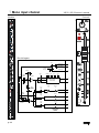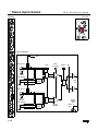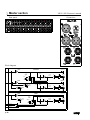
1
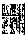
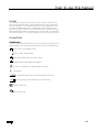
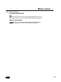
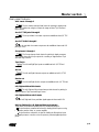
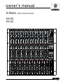
owner’s manual
X-Rack
XR-20
XR-24
rack mount mixers
Important precautions
1
Save the carton and packing materials!
Should you ever need to ship the unit,
use only the original factory packing.
For replacement packaging, call Crest Audio’s
Customer Service Department directly.
2
3
Read all documentation before
operating your equipment. Retain all
documentation for future reference.
Follow all instructions printed on
unit chassis for proper operation.
Service Information
Do not open unit!
Opening the unit will expose you to
potentially dangerous voltages. There are
no user serviceable parts inside.
Equipment should be serviced by
qualified service personnel when:
A. The equipment has been exposed to rain.
B. The equipment does not appear to oper-
ate normally, or exhibits a marked change in
performance.
C. The equipment has been dropped, or the
enclosure damaged.
4
Do not use the unit if the electrical
power cord is frayed or broken.
The power supply cord should be routed so that it is not likely to be walked on
or pinched by items placed upon or
against it.
5
Always operate the unit with the
AC ground wire connected to the
electrical system ground. Precautions
should be taken so that the means of
grounding of a piece of equipment is not
defeated.
6
Damage caused by connection to
improper AC voltage is not covered
by any warranty.
7
Do not spill water or other liquids
into or on the unit, or operate the
unit while standing in liquid.
8
The power cord of equipment
should be unplugged from the outlet when left unused for a long period of time.
To obtain service:
contact your nearest Crest Audio
Service Center, Distributor, Dealer,
or Crest Audio at 201.909.8700 USA
or visit www.crestaudio.com for additional information.
email
techserve @crestaudio.com
XR-20 / XR-24 owner’s manual
This symbol is used to alert
the operator to follow important
procedures and precautions
detailed in documentation.
This symbol is used to warn operators that uninsulated “dangerous
voltages” are present within the
equipment enclosure that may
pose a risk of electrical shock.
IMPORTANT SAFETY INSTRUCTIONS
WARNING: When using electrical products, basic cautions should always be followed, including the following:
1.
2.
3.
4.
5.
6.
7.
8.
9.
10.
11.
12.
13.
14.
15.
16.
17.
Read these instructions.
Keep these instructions.
Heed all warnings.
Follow all instructions.
Do not use this apparatus near water.
Clean only with a dry cloth.
Do not block any of the ventilation openings. Install in accordance with manufacturer’s instructions.
Do not install near any heat sources such as radiators, heat registers, stoves or other apparatus (including
amplifiers) that produce heat.
Do not defeat the safety purpose of the polarized or grounding-type plug. A polarized plug has two blades with one
wider than the other. A grounding type plug has two blades and a third grounding plug. The wide blade or third
prong is provided for your safety. If the provided plug does not fit into your outlet, consult an electrician for
replacement of the obsolete outlet.
Protect the power cord from being walked on or pinched, particularly at plugs, convenience receptacles, and the
point they exit from the apparatus.
Only use attachments/accessories provided by the manufacturer.
Use only with a cart, stand, tripod, bracket, or table specified by the manufacturer or sold with the apparatus. When
a cart is used, use caution when moving the cart/apparatus combination to avoid injury from tip-over.
Unplug this apparatus during lightning storms or when unused for long periods of time.
Refer all servicing to qualified service personnel. Servicing is required when the apparatus has been damaged in
any way, such as power-supply cord or plug is damaged, liquid has been spilled or objects have fallen into the
apparatus, the apparatus has been exposed to rain or moisture, does not operate normally, or has been dropped.
Never break off the ground pin. Write for our free booklet “Shock Hazard and Grounding.” Connect only to a power
supply of the type marked on the unit adjacent to the power supply cord.
If this product is to be mounted in an equipment rack, rear support should be provided.
Exposure to extremely high noise levels may cause a permanent hearing loss. Individuals vary considerably in
susceptibility to noise-induced hearing loss, but nearly everyone will lose some hearing if exposed to sufficiently
intense noise for a sufficient time. The U.S. Government’s Occupational and Health Administration (OSHA) has
specified the following permissible noise level exposures:
Duration Per Day In Hours
8
6
4
3
2
1 1/2
1
1/2
1/4 or less
Sound Level dBA, Slow Response
90
92
95
97
100
102
105
110
115
According to OSHA, any exposure in excess of the above permissible limits could result in some hearing loss. Ear plugs or protectors to the
ear canals or over the ears must be worn when operating this amplification system in order to prevent a permanent hearing loss, if exposure
is in excess of the limits as set forth above. To ensure against potentially dangerous exposure to high sound pressure levels, it is
recommended that all persons exposed to equipment capable of producing high sound pressure levels such as this amplification system be
protected by hearing protectors while this unit is in operation.
SAVE THESE INSTRUCTIONS!
table of contents
Introduction
Thank you and congratulations on your purchase of your new
Crest Audio X-Rack mixer. We’re confident that you will enjoy
many years of trouble-free service from it. You will quickly find
that it fits into a wide variety of mixing applications with ease.
Due to well thought out sets of features, coupled with intelligent circuit design and the highest standards in construction &
workmanship, all Crest Audio console products excel above and
beyond the competitor’s products, in every area.
This owner’s manual covers both the XR-20 and the XR-24 XRack mixers. Features are identical for both models, the only difference is the amount of Mono Inputs versus Stereo Inputs. The
XR-20 has 12 Mono inputs and 4 Stereo inputs, adding up to a
total of 20 microphone inputs. The XR-24 has 8 Mono inputs
and 8 Stereo inputs, adding up to a total of 24 microphone
Inputs.
Please read this manual thoroughly and keep it handy for future
reference. If you have any operating concerns that are not covered in this manual, or have application questions of any type,
don’t hesitate to contact Crest Audio directly either by phone,
fax, or email. Here is our technical support contact information:
Phone: (201) 909 8700
Fax: (201) 909 8744
Email: [email protected]
Mono Input channels
p. 7
Front panel controls and rear panel connections
Stereo Input channels
p.17
Front panel controls and rear panel connections
Master section
P .27
Aux masters, groups, main outs, monitor section.
Front panel controls and rear panel connectors.
Specifications
P. 47
1
2
3
4
XR-20/24 block diagram
JIMI
XR-20 / XR-24 owner’s manual
p. 4
how to use this manual
format
This manual uses a format that is intended to be easy to read, yet technical for those
who need to know all the details. For feature descriptions, this is done by devoting the
left side of each page to 1) an overall module picture, 2) a block diagram, and 3) a control closeup. These images all pertain to the features and control descriptions on the
right side of the page. The intention is to make the manual easy to read while including
all the technical details needed for getting the most out of the X-Rack - a compact, flexible, feature-rich addition to Crest Audio's growing line of audio mixing console products.
conventions
Control Icons
This manual uses symbols to illustrate what the control descriptions are referring to. This
makes it possible to avoid redundant wording and makes the control descriptions clear.
Switch in the UP, non-activated position
Switch in DOWN, activated position
Switch that illuminates when in the DOWN position
Momentary switch that illuminates when activated
LEDthat is on, indicating that it's associated feature is activated
Potentiometer
Standard 1/4" TRS jack (used for line level inputs and insert sends)
1/4" TRS jack with normal switching (used on insert returns)
Female XLRinput jack
Male XLR output jack
p. 5
1 Mono input channel
XR-20 / XR-24 owner’s manual
Module
Controls
Block diagram
+48V ON
+48V
BAL MIC IN
LINE
GAIN
12 - 70 dB
HPF
70Hz
-18dB/Oct
HPF
BAL LINE IN
27dB
PAD
p. 6
INPUT
PREAMP
Mono Input channel
1
Front panel features
Mono Input channel features are identical for both the XR-20 and the XR-24. The XR-20
has 12 Mono inputs and the XR-24 has 8 Mono inputs.
Line Input (mic pad)
The input preamp circuit is set up to accept a mic-level signal. This signal is
brought in via the XLR mic-input connector located on the rear panel. The 1/4"
TRS input jack is disabled.
The input preamp circuit is set up to accept a line-level signal from either
the XLR mic-input connector or the 1/4" TRS input jack, both located on the rear
panel. Since the sensitivity of the input preamp is reduced, this control can also act
as a PAD for bringing a very hot microphone feed down to a controllable level,
avoiding overload. When a plug is inserted into the 1/4" TRS input jack, the XLR
mic-input connector is disabled.
Gain
The Input gain control is used to establish proper gain structure in the channel. For best results, use the Solo system to monitor the channel while you set
the gain. The goal is maximum gain without distortion. Both the main LED meters
(during Solo) and the channel’s Level/Peak indicator can be used for adjusting gain.
70 Hz high-pass filter
The high-pass filter reduces or eliminates unwanted low frequencies without substantially affecting the program material. Quite often such unwanted low frequencies are included with mic- or line-input signals. For example, stage rumble or
wind can be picked up through vocal mics. The cut-off frequency of the high-pass
filter is 70 Hz and the slope is -18dB per octave.
HPF
High-pass filter is on.
p. 7
1 Mono input channel
XR-20 / XR-24 owner’s manual
Module
Controls
Block diagram
LEVEL FREQ LEVEL
FREQ LEVEL
LEVEL
HI MID
400 - 8 KHZ
HF
12 KHZ
EQ ON
LF
80 HZ
LOW MID
80 - 2 KHZ
FOUR BAND EQ
p. 8
Mono Input channel
1
Front panel features
EQ
Many audio signals coming into the console require some degree of corrective eq
in order to be part of a good sounding mix. XR-20 & XR-24 offer a very useful
and great sounding eq section on each channel. The input EQ consists of four
bands: High, High-mid, Low-mid and Low. The High and Low frequency bands each
have a boost/cut control and their frequencies are fixed. The High-mid and Lowmid bands each have variable boost/cut and variable frequency.
high frequency—HF
Boost / Cut 15dB boost and cut. Shelving @ 12 kHz
high mid—HM
Frequency Continuously sweepable between 400 Hz and 8 kHz.
Boost / Cut 15dB boost and cut. Bell curve with a Q of 1
Low mid—LM
Frequency Continuously sweepable between 100 Hz and 2 kHz.
Boost / Cut 15dB boost and cut. Bell curve with a Q of 1
Low frequency—LF
Boost / Cut 15dB boost and cut. Shelving @ 80 Hz.
EQ on
Equalizer is on. This switch is used to activate the EQ section and can be
used to make A/B comparisons between "flat" and eq'd signals.
p. 9
1 Mono input channel
XR-20 / XR-24 owner’s manual
Module
Controls
Block diagram
MUTE
EQ ON
HF
12 KHZ
PAN
CHAN
FADER
MONO
L-R
G1-2
G3-4
FADER AMP
BUS ASSIGN
SWITCHES
+10
100MM
YES
PRE
SOURCE
MUTE ?
A1-2
PRE
PAN
1-2
LEVEL
1-2
A1
A2
PRE
EQ
NO
PRE
FADER
A3-4
PRE
PRE-SOURCE
BUFFER
PRE
INSERT
PRE-SOURCE
SELECT
LEV 3
LEV 4
A5-6
PRE
LEV 5
LEV 6
AUX SENDS
1 THRU 6
p. 10
A3
A4
A5
A6
Mono Input channel
1
AUX send features
Six auxiliary sends are available for creating individual output mixes. These can be
used to drive effects processors, provide monitor mixes, create broadcast or
alternate sound reinforcement mixes, or for other special requirements.
Note: The default PRE setting for the Auxes is pre-fader, but post-mute,
post-insert, and post eq. Internal settings can be changed so that PRE is also preeq and pre mute
Aux 1 - 2 PRE
AUX 1/2 stereo pair is post fader
AUX 1/2 stereo pair is pre-fader
Aux sends 1 & 2
Auxes 1 and 2 are configured as a stereo pair. The top knob controls the level
and the bottom knob acts as a PAN control. This stereo aux send can be used for
any type of stereo feed from the console, such as live two-track recording, stereo
in-ear monitors, alternate stereo feed for broadcast, and stereo signal processors.
Also, by properly using the pan control Auxes 1 and 2 can be used as discrete
mono Aux buses
Aux 1/2 level Send level for the Aux 1/2 stereo pair
Aux 1/2 PAN Stereo placement for the Aux 1/2 stereo pair
AUX 3-4 PRE
AUX 3 and AUX 4 are post fader
AUX 3 and AUX 4 are pre-fader
Aux sends 3, 4, 5 & 6
Auxes 3, 4, 5, & 6 are configured as descrete mono aux sends. They are typically
used to feed signal processors and for on-stage monitors.
Auxes 3, 4, 5, &6 level Set levels Auxes 3, 4, 5, & 6.
AUX 5-6 PRE
AUX 5 and AUX 6 are post fader.
AUX 5 and AUX 6 are pre-fader.
p. 11
1 Mono input channel
XR-20 / XR-24 owner’s manual
Module
Controls
Block diagram
PFL
SOLO LEFT
SOLO RIGHT
TO
PEAK
CIRCUIT
SOLO DC
MUTE
EQ ON
PAN
CHAN
FADER
MONO
L-R
G1-2
G3-4
FADER AMP
BUS ASSIGN
SWITCHES
+10
100MM
YES
PRE
SOURCE
MUTE ?
A1-2
PRE
PAN
1-2
LEVEL
1-2
A1
A2
PRE
EQ
NO
PRE
FADER
A3-4
PRE
PRE-SOURCE
BUFFER
PRE-SOURCE
SELECT
LEV 3
LEV 4
A5-6
PRE
LEV 5
LEV 6
AUX SENDS
1 THRU 6
p. 12
A3
A4
A5
A6
Mono Input channel
1
Bus assignment features
The bus assignment section offers considerable flexibility for creating what eventually becomes the main output mix. Two stereo subgroups are available for creating submixes or separate stereo mixes. All assignments are derived post-fader,
post-eq, and post-mute.
PAN control
The pan control positions the signal within the stereo left/right (or
odd/even) field. PAN affects signals that are assigned directly to Left-Right, Groups
1-2 and Groups 3-4
Mono bus assign
The channel is assigned to the MONO mix bus. PAN has no affect on
MONO
L-R bus assign
The channel is assigned to the Left and Right mix buses.
G 1-2 bus assign
The channel is assigned to Groups 1 and 2. Groups 1 and 2 are configured
as a stereo pair. They can also be treated as two discrete mono groups by using
the PAN control.
G 3-4 bus assign
The channel is assigned Groups 3 and 4. Groups 4 and 4 are configured as a
stereo pair. They can also be treated as two discrete mono groups by using the
PAN control.
Input fader (100mm)
The fader is the primary level control for signals being sent to any of the consoles
post fader mix buses,
MUTE
The input channel is muted and the MUTE LED is alluminated. All AUX
feeds and bus assignments are shut off. Insert send and SOLO signals are still
active.
PK / SIG LED indicator
This two-color(green & red) LED is used to monitor the channel’s signal
level. Signal present (green) is monitored pre-fader. Peak (red) is monitored at the
preamp and before & after the fader.
PFL
PFL -Pre fader listen. This button routes the channel’s signal to the Solo bus
for monitoring through headphones or in the control room. The Peak (red) LED
is illuminated to show PFL status.
p. 13
1 Mono input channel
XR-20 / XR-24 owner’s manual
Connectors
Rear panel
Block diagram
HPF
70Hz
-18dB/Oct
GAIN
12 - 70 dB
BAL MIC IN
LINE
HPF
BAL LINE IN
INPUT
PREAMP
27dB
PAD
INSERT
SEND / RTN
POST
FADER
DIRECT OUT
SOURCE
DIRECT OUT
GC
PRE
FADER
REAR PANEL
X-RACK MONO INPUT MODULE
12 OR 8 MO NO INPUTS AVAILABLE
PFL
SOLO LEFT
+48V ON
+48V
SOLO RIGHT
GAIN
12 - 70 dB
BAL MIC IN
LINE
TO
PEAK
CIRCU IT
HPF
70Hz
-18dB/Oct
LEVEL FREQ LEVEL
FREQ LEVEL
LEVEL
PAN
EQ ON
LF
80 HZ
HPF
LOWMID
80 - 2 KHZ
HI MID
400 - 8 KHZ
HF
12 KHZ
CHAN
FAD ER
INPUT
SIGNAL
LED
INSERT
SEND / RTN
POST
FAD ER
DIRECT OUT
GC
PRE
FADER
REAR PANEL
G1-2
G3-4
100MM
SOLO
TRIGGER
YES
PRE
SOURCE
MUTE ?
PEAK R
(PFL)
DIRECT OUT
SOURCE
L-R
BUS ASSIG N
SW ITCH ES
+10
INPUT
PREAMP
27dB
PAD
MONO
FADER AMP
FOUR BAND EQ
BAL LINE IN
SOLO DC
MUTE
A1-2
PRE
PAN
1-2
LEVEL
1-2
A1
A2
SIG
PRE
EQ
G
NO
PRE
FADER
POST
FADER
PRE
FADER
A3-4
PRE
PRE-SOURCE
BUFFER
LEV 3
A3
LEV 4
A4
PRE
INSERT
PRE-SOURCE
SELECT
A5-6
PRE
LEV 5
A5
LEV 6
A6
AUX SENDS
1 THRU 6
p. 14
Mono Input channel
1
Rear panel features
48 V Phantom power
48 volts DC is applied to pins 2 and 3 on the mic-input XLR connector.This
option is used with condenser microphones and active direct boxes that require
an external DC voltage (phantom power ) in order to operate.
Line INPUT jack
Line-level signals, balanced or unbalanced, may be brought into the
input channel through this jack. The LINE INPUT switch must be pressed for this
jack to be active.
MIC INPUT jack
This balanced female XLR accepts a low-impedance microphone signal, or a
line-level signal, depending on the position of the LINE INPUT switch on the front
panel.
INSERT jack
This switching 1/4” TRS jack allows an external signal processor to be
inserted into the signal path of the channel. The tip carries the SEND signal and
the ring carries the RETURN signal.
DIRECT OUT jack
The channel’s signal can be brought out of the console via the direct
out jack. The signal that appears at this jack is normally post fader.There is an
internal option for making it pre fader.
p. 15
1 Stereo input channel
XR-20 / XR-24 owner’s manual
Controls
Module
Block diagram
+48V ON
+48V
BAL MIC IN
LINE
GAIN
15 - 60 dB
MONO
BAL
LEFT
BAL LINE IN
27dB
PAD
PRE
EQ
BAL MIC IN
RIGHT
INPUT
SIGNAL
LED
BAL LINE IN
27dB
PAD
INPUT
PREAMP
PEAK R
(PFL)
SIG
p. 16
Stereo Input channel
1
Front panel features
Stereo Input channels features are identical for both the XR-20 and the XR-24. The XR20 has 4 Stereo inputs, and the XR-24 has and 8 Stereo inputs. On both models the
Stereo inputs are located to the left of the master section, to the right of the Mono
inputs. They can be treated as mono input channels, or as Stereo input channels.
Stereo Line Input (mic pad)
The stereo input preamp circuit is set up to accept mic-level signals. The signals are brought in via the XLR mic-input connectors located on the rear panel.
The 1/4" TRS input jacks are disabled.
The stereo input preamp circuits are set up to accept line-level signals from
either the XLR mic-input connectors or the 1/4" TRS input jacks, all located on
the rear panel. Since the sensitivity of the stereo input preamp is reduced, this
control can also act as a PAD for bringing very hot microphone feeds down to a
safe level, avoiding overload. When a plug is inserted into a 1/4" TRS input jack, the
XLR connector is disabled.
Gain
The Input gain control is used to establish proper gain structure in the channel. The GAIN control affects both the Left and Right input signals. For best
results, use the Solo system to monitor the channel while you set the gain. The
goal is maximum gain without distortion. Both the main LED meters (during Solo)
and the channel’s Level/Peak indicator can be used for adjusting gain.
SUM INPUTS
By summing the inputs, a stereo input channel can be used as a mono input channel.
The channel functions as a stereo input.
If signals are applied to both the Left and Right input jacks, they will be
summed together as a mono signal. If a signal is applied to just one of the input
jacks, it will be treated as a mono signal throughout the rest of the channel.
p. 17
1 Stereo input channel
XR-20 / XR-24 owner’s manual
Controls
Module
Block diagram
PRE
FADER
ONO
LEVEL FREQ LEVEL
BAL
FREQ LEVEL
LEVEL
HI MID
400 - 8 KHZ
HF
12 KHZ
MUTE
EQ ON
LF
80 HZ
LOW MID
80 - 2 KHZ
CHAN
FADER
FOUR BAND EQ - LEFT
PRE
EQ
LF
80 HZ
LOW MID
80 - 2 KHZ
HI MID
400 - 8 KHZ
FOUR BAND EQ - RIGHT
p. 18
HF
12 KHZ
100MM
FA
Stereo Input channel
1
Front panel features
Stereo EQ
The Stereo Input channel has two parallel EQ circuits that are controlled by the
same set of knobs.
high frequency—HF
Boost / Cut 15dB boost and cut. Shelving @ 12 kHz
high mid—HM
Frequency Continuously sweepable between 400 Hz and 8 kHz.
Boost / Cut 15dB boost and cut. Bell curve with a Q of 1
Low mid—LM
Frequency Continuously sweepable between 100 Hz and 2 kHz.
Boost / Cut 15dB boost and cut. Bell curve with a Q of 1
Low frequency—LF
Boost / Cut 15dB boost and cut. Shelving @ 80 Hz.
EQ on
Equalizer is on. This switch is used to activate the EQ section and can be
used to make A/B comparisons between "flat" and eq'd signals.
p. 19
2 Stereo input channel
XR-20 / XR-24 owner’s manual
Controls
Module
Block diagram
PFL
SOLO LEFT
PRE
FADER
SOLO RIGHT
TO
PEAK
CIRCUIT
MUTE
SOLO DC
MONO
L-R
G1-2
G3-4
FADER AMPS
CHAN
FADER
LEFT
+10
BUS ASSIGN
SWITCHES
POST
FADER
+10
RIGHT
100MM
A1-2
PRE
PAN
1-2
LEVEL
1-2
LEFT
A1
RIGHT
A2
YES
PRE
SOURCE
MUTE ?
A3-4
PRE
LEV 3
L&R
MIXED
NO
LEFT
PRE-SOURCE
BUFFERS
A5-6
PRE
LEV 4
A4
LEV 5
L&R
MIXED
A5
LEV 6
A6
RIGHT
AUX SENDS
1 THRU 6
p. 20
A3
Stereo Input channel
2
AUX send features
Six auxiliary sends are available for creating individual output mixes. These can be
used to drive effects processors, provide monitor mixes, create broadcast or
alternate sound reinforcement mixes, or for other special requirements.
Note: The default PRE setting for the Auxes is pre-fader, but post-mute,
post-insert, and post eq. Internal settings changed be changed so that PRE is also
pre-eq and pre mute
Aux 1 - 2 PRE
AUX 1/2 stereo pair is post fader
AUX 1/2 stereo pair is pre-fader
Aux sends 1 & 2
Auxes 1 and 2 are configured as a stereo pair. If the channel is configured as a
stereo input, the Left and Right signals are routed to Auxes 1 and 2, retaining the
stereo split. The PAN knob acts as a balance control. This stereo aux send can be
used for any type of stereo feed from the console, such as live two-track recording, stereo in-ear monitors, alternate stereo feed for broadcast, and stereo signal
processors. Also, by using the pan control to select a single bus, Auxes 1 and 2
can be used as discrete mono Aux buses
Aux 1/2 level Sets level for the Aux 1/2 stereo pair
Aux 1/2 PAN If the MONO SUM button is up, this knob controls the
stereo balance for Auxes 1 and 2. If the MONO SUM button is down, the
summed signal is panned between Auxes 1 and 2
AUX 3-4 PRE
AUX 3 and AUX 4 are post fader
AUX 3 and AUX 4 are pre-fader
Aux sends 3, 4, 5 & 6
Auxes 3, 4, 5, & 6 are configured as descrete mono aux sends. They are typically
used to feed signal processors and for on-stage monitors. Stereo signals are
summed together to make up the source for Auxes 3, 4, 5 & 6.
Auxes 3, 4, 5, & 6 level Set levels Auxes 3, 4, 5, & 6.
AUX 5-6 PRE
AUX 5 and AUX 6 are post fader.
AUX 5 and AUX 6 are pre-fader.
p. 21
2 Stereo input channel
XR-20 / XR-24 owner’s manual
Controls
Module
PFL
SOLO LEFT
PRE
FADER
SOLO RIGHT
TO
PEAK
CIRCUIT
MUTE
SOLO DC
MONO
L-R
G1-2
G3-4
FADER AMPS
CHAN
FADER
LEFT
+10
BUS ASSIGN
SWITCHES
POST
FADER
+10
RIGHT
100MM
A1-2
PRE
PAN
1-2
LEVEL
1-2
LEFT
A1
RIGHT
A2
YES
PRE
SOURCE
MUTE ?
A3-4
PRE
LEV 3
L&R
MIXED
NO
LEFT
PRE-SOURCE
BUFFERS
A5-6
PRE
LEV 4
A4
LEV 5
L&R
MIXED
A5
LEV 6
A6
RIGHT
AUX SENDS
1 THRU 6
p. 22
A3
Stereo Input channel
2
Bus assignment features
The bus assignment section offers considerable flexibility for creating what eventually becomes the main output mix. Two stereo subgroups are available for creating submixes or separate stereo mixes. When the channel is being used as a
stereo input, Left/Right, Groups 1 & 2 Groups 3/4 bus assignments are configured
as true stereo pairs. Bus assignments are derived post-fader, post-eq, and postmute.
BAL control
The balance control adjusts the stereo balance for the Group and Left/Right
assignments.
Mono bus assign
The channel is assigned to the MONO mix bus. The Left and Right signals a
are summed to make up the MONO signal. BAL has no affect on MONO
L-R bus assign
The channel is assigned to the Left and Right mix buses.
G 1-2 bus assign
The channel is assigned Sub Groups 1 and 2. Groups 1 and 2 are configured
as a stereo pair. They can also be treated as two discrete mono groups by using
the BAL control as an GROUP 1/2 mix control.
G 3-4 bus assign
The channel is assigned Sub Groups 3 and 4. Groups 4 and 4 are configured
as a stereo pair. They can also be treated as two discrete mono groups by using
the BAL control as an GROUP 3/4 mix control.
Input fader
The fader is the primary level control for signals being sent to any of the consoles
mix buses, The signals affected are the AUX sends selected to be post-fader and
the Mono, L/R, and Groups 1-4.
MUTE
The input channel is muted and the MUTE LED is alluminated. All AUX
feeds and bus assignments are shut off. SOLO is still active.
PK / SIG LED indicator
This two-color(green & red) LED is used to monitor both the channel’s Left
and Right signal levels. Signal present (green) is monitored pre-fader. Peak (red ) is
monitored at the preamp and both before & after the fader.
PFL
PFL -Pre fader listen. This button routes the channel’s signal to the PFL bus
for monitoring through headphones or in the control room. The Peak (red) LED
is illuminated to show PFL status.Since the SOLO bus is stereo, stereo image is
preserved.
p. 23
2 Stereo input channel
XR-20 / XR-24 owner’s manual
Connectors
Rear panel
Block diagram
BAL MIC IN
LINE
GAIN
15 - 60 dB
MONO
LEVEL FREQ LEVEL
BAL
LF
80 HZ
LEFT
LOW MID
80 - 2 KHZ
FOUR BAND
BAL LINE IN
27dB
PAD
PRE
EQ
LF
80 HZ
LOW MID
80 - 2 KHZ
BAL MIC IN
FOUR BAND
RIGHT
SOLO
TRIGGER
INPUT
SIGNAL
LED
BAL LINE IN
INPUT
PREAMP
27dB
PAD
PRE-AMP
OUT
L&R
PEAK R
(PFL)
SIG
G
REAR PANEL
POST
FADER
X-RACK STEREO INPUT MODULE
4 OR 8 STEREO INPUTS AVAILABLE
+48V ON
PFL
SOLO LEFT
+48V
PRE
FADER
BAL MIC IN
LINE
GAIN
15 - 60 dB
MONO
LEVEL FREQ LEVEL
BAL
FREQ LEVEL
LEVEL
SOLO RIGHT
TO
PEAK
CIRCUIT
MUTE
SOLO DC
EQ ON
LF
80 HZ
LEFT
LOW MID
80 - 2 KHZ
HI MID
400 - 8 KHZ
MONO
HF
12 KHZ
L-R
G1-2
G3-4
FADER AMPS
CHAN
FADER
LEFT
FOUR BAND EQ - LEFT
BAL LINE IN
+10
27dB
PAD
BUS ASSIGN
SWITCHES
POST
FADER
PRE
EQ
+10
LF
80 HZ
BAL MIC IN
LOW MID
80 - 2 KHZ
HI MID
400 - 8 KHZ
HF
12 KHZ
RIGHT
100MM
A1-2
PRE
FOUR BAND EQ - RIGHT
PAN
1-2
LEVEL
1-2
LEFT
YES
RIGHT
SOLO
TRIGGER
INPUT
SIGNAL
LED
BAL LINE IN
27dB
PAD
INPUT
PREAMP
PRE
SOURCE
MUTE ?
PRE-AMP
OUT
L&R
PEAK R
(PFL)
PRE
FADER
POST
FADER
L&R
PRE
FADER
L&R
p. 24
PRE
FADER
RIGHT
PRE-SOURCE
BUFFERS
PRE
EQ
LEV 3
L&R
MIXED
LEFT
PRE
EQ
G
A3-4
PRE
NO
LEFT
SIG
REAR PANEL
A1
A2
RIGHT
A5-6
PRE
LEV 4
LEV 5
L&R
MIXED
A4
A5
LEV 6
A6
RIGHT
PRE-SOURCE
SELECT
A3
AUX SENDS
1 THRU 6
Stereo Input channel
2
Rear panel features
48 V Phantom power
48 volts DC is applied to pins 2 and 3 on the mic-input XLR connectors.
This option is used with condenser microphones and active direct boxes that
require an external DC voltage (phantom power ) in order to operate.
Line INPUT jacks - Left and Right
Line-level signals, balanced or unbalanced, may be brought into the
input channel through this jack. The LINE INPUT switch must be pressed for
these jack to be active.
MIC INPUT jack - Left and Right
These balanced female XLRs accept low-impedance microphone signals, or
line-level signals, depending on the position of the LINE INPUT switch on the
front panel.
p. 25
3 Master section
XR-20 / XR-24 owner’s manual
Module
Controls
Block diagram
+9
6
3
0
-3
6
9
12
15
18
21
24
LED
METERS
FOLLOW SOLO,
NORMALLY SHOW
L / R OUT
LEFT OUT
RIGHT OUT
SOLO FEED
L-R
ADD
MONO
SOLO CTRL
RIGHT
PRE-FADER
SOLO
ON
L-R
MONO
GC
L
R
GC
AUX1-2 TAPE IN
MONITOR
LEVEL
SOLO OFF
SUM
MONO
TO
PHO NES
MO N-L
MO N-R
GC
L
MONITOR SOURCE SELECT
( SELECTED SOURCES ADD TOGETHER )
MONITOR
OUT
R
GC
SOLO FEED
L-R
SOLO CTRL
TAPE-IN
LEVEL
TAPE TO
AUX 1-2
SOLO
MIX AMPS
SOLO LEFT
SOLO
FEED
L-R
AUX-1 BUS
LEFT BUS
TAPE-IN L
SOLO RIGHT
AUX-2 BUS
R IGH T BUS
TAPE IN
L
SOLO DC
TAPE TO
L/R
TAPE-IN R
SOLO
CTRL
SO LO
CO NTRO L
LOG IC
TO:
PHONES
&
MONITOR
ADD
MONO
(RECESSED)
TAPE IN
R
TAPE
IN
FROM
MONITOR
SOLO
OFF
HEADPHONE
LEVEL
LEFT OUT
TAPE-IN L
MON-L
L
MON-R
R
RIGHT OUT
TAPE-IN R
MONO OUT
MONO PRE
TO
ALT-OU T
SOLO FEED
L-R
SOLO CTRL
p. 26
ALT
OUT
PWR
ON
AUDIO SOURCES FOR MONITOR - ALL PRE-FADER
GRP3-4 GRP1-2
ALT
LEVEL
LEFT
PRE-FADER
HEADPHONE
AMPS
TO:
PHONES,
MONITOR
&
METERS
Master section
3
Front panel features
The XR-20 & XR-24 have a comprehensive output section, including meters, master
level controls, and a flexable group assignment section.
Headphone control section
In normal use, the headphone out is used to monitor the Solo system. The Solo
system is made up of anything that is PFL’d (pre-fader-listen) or AFL’s (after fader
listen).
The hirarchy of what appears in the headphones when nothing is soloed, or when
the SOLO OFF button is pressed is as follows:
MONITOR when FROM MONITOR is engaged.
TAPE IN whenTAPE IN is engaged and FROM MONITOR is not engaged.
LEFT and RIGHT masters when neither FROM MONITOR nor TAPE IN
are engaged.
ADD
MONO
(RECESSED)
TAPE
IN
FROM
MONITOR
SOLO
OFF
HEADPHONE
LEVEL
LEFT OUT
TAPE-IN L
MON-L
L
MON-R
R
RIGHT OUT
TAPE-IN R
MONO OUT
MONO PRE
HEADPHONE
AMPS
TO
ALT-OUT
SOLO FEED
L-R
SOLO CTRL
Headphone jack
This 1/4” TRS jack is intended for stereo headphones. It can also be
used as a stereo control-monitor output from the mixer. From this jack you can
get a number of signals, including SOLO, Left, Right & Mono, and Monitor / Tape
feeds.
Headphone level
This knob controls the level that appears at the Headphone Jack.
SOLO OFF
Solo (PFL or AFL) overrides the default headphone signals unless this button is
depressed.
Whenever something is Soloed, it appears in the headphones.
Soloed signals do not appear in the headphones.
p. 27
3 Master section
XR-20 / XR-24 owner’s manual
Controls
Module
Block diagram
+9
6
3
0
-3
6
9
12
15
18
21
24
LED
METERS
FOLLOW SOLO,
NORMALLY SHOW
L / R OUT
LEFT OUT
RIGHT OUT
SOLO FEED
L-R
ADD
MONO
SOLO CTRL
RIGHT
PRE-FADER
SOLO
ON
L-R
MONO
GC
L
R
GC
AUX1-2 TAPE IN
MONITOR
LEVEL
SOLO OFF
SUM
MONO
TO
PHO NES
MO N-L
MO N-R
GC
L
MONITOR SOURCE SELECT
( SELECTED SOURCES ADD TOGETHER )
MONITOR
OUT
R
GC
SOLO FEED
L-R
SOLO CTRL
TAPE-IN
LEVEL
TAPE TO
AUX 1-2
SOLO
MIX AMPS
SOLO LEFT
SOLO
FEED
L-R
AUX-1 BUS
LEFT BUS
TAPE-IN L
SOLO RIGHT
AUX-2 BUS
R IGH T BUS
TAPE IN
L
SOLO DC
TAPE TO
L/R
TAPE-IN R
SOLO
CTRL
SO LO
CO NTRO L
LOG IC
TO:
PHONES
&
MONITOR
ADD
MONO
(RECESSED)
TAPE IN
R
TAPE
IN
FROM
MONITOR
SOLO
OFF
HEADPHONE
LEVEL
LEFT OUT
TAPE-IN L
MON-L
L
MON-R
R
RIGHT OUT
TAPE-IN R
MONO OUT
MONO PRE
TO
ALT-OU T
SOLO FEED
L-R
SOLO CTRL
p. 28
ALT
OUT
PWR
ON
AUDIO SOURCES FOR MONITOR - ALL PRE-FADER
GRP3-4 GRP1-2
ALT
LEVEL
LEFT
PRE-FADER
HEADPHONE
AMPS
TO:
PHONES,
MONITOR
&
METERS
Master section
3
Front panel features
FROM MONITOR
The post-level control MONITOR output becomes the signal in the headphones when nothing is soloed. This overrides TAPE IN if the TAPE IN button is
depressed.
TAPE IN
The TAPE IN signals appear in the headphones when the FROM MONITOR
button is not depressed and nothing is Soloed.
ADD MONO to Phones and ALT OUT
Mono, or Center can be added when the LEFT and RIGHT masters are present
at the Phone out, on the front panel and the ALT OUT jacks on the rear panel.
The switch is recessed to prevent it’s state from acidentaly being switched.
The default signal at the Headphone output and the ALT OUT jacks is the
stereo LEFT/RIGHT mix.
In addition to the LEFT/RIGHT mix at he the Headphone output and the
ALT OUT jacks, the MONO master signal is blended in.
12 V Lamp jack
A BNC jack is used for hooking up a goose-neck lamp. The center connection is
12 Volts DC and the outer connection is ground. A medium or high-intensity 12V
DC Littlite is can be used.
LED meters - Left and Right
A pair of LED arrays are provided for monitoring the output levels. They follow the SOLO system, making it easy to adjust input and output levels by PFL’ing
and AFL’ing different sources. They normally show the LEFT and RIGHT output
levels. When something is Soloed, it replaces LEFT and RIGHT on the meters.
SOLO LED
This red LED lights up when anything on the mixer is soloed.
PWR LED
This green LED illuminates to indicate that the mixer is powered up and
ready for use.
p. 29
3 Master section
XR-20 / XR-24 owner’s manual
Controls
Module
Block diagram
TAPE-IN
LEVEL
TAPE TO
AUX 1-2
AU
LEFT BUS
TAPE-IN L
AU
RIGHT BUS
TAPE IN
L
TAPE TO
L/R
TAPE-IN R
TO:
PHONES
&
MONITOR
ADD
MONO
(RECESSED)
TAPE IN
R
LEFT OUT
TAPE-IN L
X-RACK AUX BUSES 1-2
(STEREO PAIR)
AUX 1
AUX
MIX AMPS
INSERT
SEND / RTN
AUX 2
AUX 1-2
MASTER
AFL
SOLO LEFT
+10
AUX 1
OUT
AUX 2
OUT
GC
SOLO RIGHT
GC
+10
SOLO DC
AUX
MIX AMP
X-RACK AUX BUSES 3 THRU 6
(1 OF 4 SHOWN)
INSERT
SEND / RTN
AUX
MASTER
AFL
SOLO LEFT
+10
SOLO RIGHT
AUX
OUT
SOLO DC
GC
p. 30
Master section
3
Front panel features
TAPE IN level
On the rear panel there are Left and Right TAPE IN connectors, both 1/4”
TRS and RCA. They can be used to bring in a stereo source such as a two-track
playback from tape, CD, MD, or a sampler. This knob controls the level to the Aux
1/2 and Left/Right buses.
TAPE IN assignment
TO A1-2 This assigns the stereo TAPE IN to Auxes 1 and 2, which are configured as a stereo pair. This is useful for stereo program monitoring.
TO L-R This assigns the stereo TAPE IN feed to the Left and Right mix
buses. This is useful for in-between-set background music and as an extra stereo
return.
AUX OUT 1-2 level control
This is the master stereo output level control for the AUX 1/2 pair.
Aux 1-2 AFL
This button assigns the AUX 1/2 stereo pair to the solo system. Since it is
AFL, the signal is monitored after the AUX insert and master level control. Auxes
1 & 2 show up in stereo in the System - 1 on the left and 2 on the right.
AUX OUT 3, 4, 5 & 6 level controls
These are the master output level controls for Auxes 3, 4, 5 &6.
Aux 3, 4, 5, & 6 AFL
These buttons assign Auxes 3, 4, 5 & 6 to the solo system. Since they are
AFL, the signals are monitored after the AUX inserts and master level controls.
p. 31
3 Master section
XR-20 / XR-24 owner’s manual
Controls
Module
Block diagram
X-RACK GROUPS
(1 OF 4 SHOWN)
GROUP
MIX AMP
INSERT
SEND / RTN
PRE
FADER
MONO
LEFT
RIGHT
GROUP-TO-MAIN
ASSIGN
SWITCHES
ODD GROUPS FEED
LEFT SOLO, EVENS
FEED RIGHT SOLO
GROUP
FADER
POST
FADER
PEAK R
(AFL)
AFL
SIG
SOLO DC
p. 32
G
GROUP
BUS IN
+10
GROUP
LED
SOLO LEFT
SOLO RIGHT
TO GROUP
MIX-AMP
GROUP
OUT
60MM
GC
Master section
3
Front panel features
GROUP assignment section
The XR-20 offers a flexible group assignment arrangement. Each of the four
Groups can be assigned to Left, Right and Mono busses, in any combination.
M - Mono assignments for Groups 1, 2, 3 & 4
Each of the four groups has a Mono assignment button for
routing its post-fader signal to the Mono mix bus.
L - Left assignments for Groups 1, 2, 3 & 4
Each of the four groups has a Left assignment button for
routing its post-fader signal to the Left mix bus.
R - Right assignments for Groups 1, 2, 3 & 4
Each of the four groups has a Right assignment button for
routing its post-fader signal to the Right mix bus.
Group Master Faders 1, 2, 3 & 4
Each Group has a master fader for adjusting its overall level. These signals show
up at the Group OUT jacks on the rear panel and can be assigned to the Left,
Right and Mono buses. They also feed the Solo system when the Group AFL buttons are down.
GroupPK / SIG LED indicators
These two-color(green & red) LEDs are used to monitor
each of the group’s signal levels. Signal present (green) is monitored pre-fader. Peak
(red ) is monitored at the preamp and both before & after the fader.
AFL buttons for Groups 1, 2, 3 & 4
Each of the four groups has an AFL button for monitoring
through the SOLO system. The signal assigned to the Solo bus is picked up after
the fader. The groups show up in stereo in the Solo system - odd - left, even right. The Peak (red) LEDs are illuminated to show AFL status.
p. 33
3 Master section
XR-20 / XR-24 owner’s manual
Controls
Module
Block diagram
AUDIO SOURCES FOR MONITOR - ALL PRE-FADER
GRP3-4 GRP1-2
L-R
MONO
AUX1-2 TAPE IN
MONITOR SOURCE SELECT
( SELECTED SOURCES ADD TOGETHER )
SOLO FEED
L-R
SOLO CTRL
p. 34
MONITOR
LEVEL
SOLO OFF
SUM
MONO
TO
PHONES
MON-L
MON-R
L
GC
R
GC
MONITOR
OUT
Master section
3
Front panel features
MONITOR Output section
The XR-20 and XR-24 offer an extensive monitoring system which can be used
for several alternate mix and remote listening purposes. The main L/R & M mixes,
the Groups, Auxes 1&2, the Tape IN, and the Solo system can all be routed to the
Monitor outs. Like the Headphone section, the SOLO system is automatically
routed to the Monitors. This can be defeated by pressing the SOLO OFF button.
MONITOR Level control
This knob controls the signal level that appears at the Monitor output on
the rear panel. This signal can also be assigned to the headphone system by pressing the FROM MONITOR button located below the Headphone level control.
SUM MONO
The MONITOR System operates in stereo, and has Left and Right outputs.You
can assign several stereo sources to the Monitor bus,including the Aux 1/2 stereo
pair, the Left/Right busses, the TAPE IN, and the Groups,in stereo odd/even pairs.
The MONITOR system operates in stereo. . Any stereo signals that are
assigned to the Monitor system remain stereo.
The MONITOR system operates in mono. Any stereo signals that are
assigned to the Monitor system are summed together.
SOLO OFF
Like the Headphone section, the Solo system is automatically routed to the monitors.
.Solo takes overrides anything that is assigned to the monitors.
The Solo system does not appear in the monitors.
Note
If you are 1) routing the Monitor outs to the Headphone system by pressing the
FROM MONITOR button in the Headphone section, and, 2) you don’t want the
Solo system to show up in the headphones, you must press both SOLO OFF buttons -the one in the Headphone section and the one in the Monitor section.
p. 35
3 Master section
XR-20 / XR-24 owner’s manual
Controls
Module
Block diagram
AUDIO SOURCES FOR MONITOR - ALL PRE-FADER
GRP3-4 GRP1-2
L-R
MONO
AUX1-2 TAPE IN
MONITOR SOURCE SELECT
( SELECTED SOURCES ADD TOGETHER )
SOLO FEED
L-R
SOLO CTRL
p. 36
MONITOR
LEVEL
SOLO OFF
SUM
MONO
TO
PHONES
MON-L
MON-R
L
GC
R
GC
MONITOR
OUT
Master section
3
Front panel features
MONITOR Output section
SOURCE SELECT
The Source select portion of the Monitor system allows you do assign the primary mix buses to the Monitor outputs. All assignments are post insert, pre-fader. All
selected sources are added (summed) together.
TAPE IN
Assigns the TAPE IN L & R signals to the monitors. The TAPE IN jacks are
located on the rear panel. 1/4” TRS jacks and RCA phone plugs are provided for
easy hookup.
A1-2 (Aux 1 & 2)
Assigns Auxes 1 and 2 to the Monitor outputs. Auxes 1 and 2 are configured as one stereo Aux bus (see Mono input channel description). 1 is Left and 2
is Right.
MONO
Assigns the Mono bus to both the Left and Right Monitor outs.
L-R (Left & Right)
Assigns the Left and Right buses to the Left and Right Monitor outs.
G1-2 (Groups 1 & 2)
Assigns Groups 1 and 2 to the Monitor outs.1 is Left and 2 is Right
G3-4 (Groups 2 & 4)
Assigns Groups 3 and 4 to the Monitor outs. 3 is Left and 4 is Right.
p. 37
3 Master section
XR-20 / XR-24 owner’s manual
Controls
Module
Block diagram
X-RACK MAIN OUT
LEFT-RIGHT
LEFT
MIX AMP
L-PRE
FADER
L/ R
SIGNAL
LED
PEAK
SIG
RIGHT
MIX AMP
L-INSERT
SEND / RTN
LEFT
FADER
MIC LEVEL
L-POST
FADER
+10
R
LEFT
BAL OUT
30dB
PAD
100MM
G
R-INSERT
SEND / RTN
RIGHT
BUS IN
R-PRE
FADER
MIC LEVEL
RIGHT
FADER
R-POST
FADER
LEFT
BUS IN
+10
RIGHT
BAL OUT
30dB
PAD
100MM
X-RACK MAIN OUT
MONO
MONO
MIX AMP
MONO
SIGNAL
LED
MONO
BUS IN
M-PRE
FADER
SIG
SOLO DC
p. 38
G
MIC LEVEL
M-POST
FADER
PEAK R
(AFL)
+10
AFL
SOLO LEFT
SOLO RIGHT
M-INSERT
SEND / RTN
MONO
FADER
100MM
MONO
BAL OUT
30dB
PAD
Master section
3
Front panel features
Mono PK/SIG LED
Green/Red - Flashes to indicate the Mono master level. Green during normal operation and red to indicate overload either at the mix amp or at the fader.
Left/Right PK/SIG LED
Green/Red - Flashes to indicate the summed Left/Right master levels. Green
during normal operation and red to indicate overload either at the mix amps or
at the faders.
MONO AFL
Assigns the post-fader Mono master signal to Solo bus, and illuminates the
Peak (red) LED.
MONO, LEFT & RIGHT Master faders (100mm)
These are the master level controls for the main Left, Right and Mono outputs.
ALT OUT (L-R)
Sets the level for the Alternate Left & Right outputs. These outputs are
made up of the pre-fader Left/Right mix. If the ADD MONO TO PHONES & ALT
OUT button is depressed, the pre-fader MONO mix becomes part of the ALT
OUT as well. Jacks are located on the rear panel. 1/4” TRS and RCA jacks are
provided for easy hookup.
p. 39
3 Master section
XR-20 / XR-24 owner’s manual
Connectors
Rear panel
Block diagram
X-RACK MAIN OUT
LEFT-RIGHT
LEFT
MIX AMP
L-PRE
FADER
L/R
SIGNAL
LED
PEAK
SIG
RIGHT
MIX AMP
L-INSERT
SEND / RTN
LEFT
FADER
MIC LEVEL
L-POST
FADER
+10
R
LEFT
BAL OUT
30dB
PAD
100MM
G
R-INSERT
SEND / RTN
RIGHT
BUS IN
R-PRE
FADER
MIC LEVEL
RIGHT
FADER
R-POST
FADER
+10
LEFT
BUS IN
RIGHT
BAL OUT
30dB
PAD
100MM
X-RACK MAIN OUT
MONO
MONO
MIX AMP
MONO
SIGNAL
LED
MONO
BUS IN
M-PRE
FADER
MONO
FADER
PEAK R
(AFL)
SIG
SOLO RIGHT
SOLO DC
p. 40
G
MIC LEVEL
M-POST
FADER
+10
AFL
SOLO LEFT
M-INSERT
SEND / RTN
100MM
MONO
BAL OUT
30dB
PAD
Master section
3
Rear panel features
Left, Right and Mono bus inputs
These three female XLR’s are used to bring external signals directly into the
Left, Right and Mono mix buses. This is useful for linking multiple mixers together.
Group 1, 2, 3 & 4 bus inputs
These 1/4” TRS jacks are used to bring external signals directly into
the first four sub groups. This is useful for linking multiple mixers together.
p. 41
3 Master section
XR-20 / XR-24 owner’s manual
Rear panel
Block diagram
X-RACK GROUPS
(1 OF 4 SHOWN)
GROUP
MIX AMP
INSERT
SEND / RTN
PRE
FADER
MONO
LEFT
RIGHT
GROUP
FADER
POST
FADER
GROUP-TO-MAIN
ASSIGN
SWITCHES
ODD GROUPS FEED
LEFT SOLO, EVENS
FEED RIGHT SOLO
GROUP
BUS IN
TO GROUP
MIX-AMP
+10
GROUP
LED
GROUP
OUT
60MM
PEAK R
(AFL)
GC
AFL
SOLO LEFT
SIG
G
SOLO RIGHT
SOLO DC
X-RACK AUX BUSES 1-2
(STEREO PAIR)
AUX 1
AUX
MIX AMPS
INSERT
SEND / RTN
AUX 2
AUX 1-2
MASTER
A FL
SOLO LEFT
+10
AUX 1
OUT
AUX 2
OUT
GC
SOLO RIGHT
GC
+10
SOLO DC
AUX
MIX AMP
X-RACK AUX BUSES 3 THRU 6
(1 OF 4 SHOWN)
INSERT
SEND / RTN
AUX
MASTER
AFL
SOLO LEFT
+10
SOLO RIGHT
AUX
OUT
SOLO DC
GC
p. 42
Master section
3
Rear panel features
AUX Inserts 1 through 6
The Aux masters have pre-fader inserts for patching in signal processors. This is useful when using Aux outputs for stage monitors. Tip is Send and
Ring is Return.
Aux OUT TRS Jacks 1 through 6
The six post-fader Aux master outputs are available at these 1/4” TRS
jacks.
Aux OUT XLR’s 1 through 6
The six post-fader Aux master outputs are also available at these male XLR
jacks. (pin 2 hot)
Group Inserts 1 through 4
The Groups have pre-fader inserts for patching in signal processors.
This is useful when using Group outputs for recording or stage monitors. Tip is
Send and Ring is Return.
Tape (line) in
The Left and Right Tape inputs are available as both 1/4” TRS and
RCA.
Alt Out
The Left and Right Alternate outputs are available as both 1/4” TRS
and RCA.
Monitor out
The Left and Right Monitor outputs are available as both 1/4” TRS and
RCA.
Left, Right and Mono Main Inserts
The Left, Right and Mono buses have pre-fader inserts for patching in
signal processors. Tip is Send and Ring is Return.
Left, Right and Mono main Outputs
The Left, Right and Mono post-fader signals appear at these male XLR’s.
Mic/Line Switches for Left, Right and Mono main outputs
These switch are recessed to prevent the from accidentally being hit
Output levels are presented at line level for feeding the line inputs on a signal processor, another mixer, or a power amplifier.
Output levels are reduced to mic level for feeding the Microphone inputs
on a signal processor or another mixer. Outputs are protected against phantom
power.
p. 43
3 Master section
XR-20 / XR-24 owner’s manual
Use 5-Pin DIN cable to
interconnect two Consoles
SOLO
LINK
IN
OUT
SOLO-LINK:
TIES SOLO AUDIO AND
CONTROL BETWEEN
CONSOLES. SLAVE SOLOS
SHOW UP ON MASTER
CONSOLE.
SOLO-LINK CONNECTORS.
USE 5-PIN DIN CABLE FROM
SLAVE CONSOLE OUT
TO MASTER CONSOLE IN
ON
P
O
W
E
R
BNC CONNECTOR
FOR 12VOLT LAMP
( ON FRONT PANEL )
POLY
FUSES
SHORT-CIRCUIT
PROTECTION
+17V
-17V
UNIVERSAL INPUT-VOLTAGE
SWITCHING POWER SUPPLY
AC IN
100-240V
50 / 60 Hz
80W
+48V
ANALOG
GROUND
INTERNALLY FUSED AND
SHORT-CIRCUIT PROTECTED
+12V
AUX DC
GROUND
X-RACK REAR PANEL:
AC INLET & SWITCH
SAFETY
GROUND
p. 44
CHASSIS
GROUND
TO POWER
DISTRIBUTION
RIBBONS
Master section
3
Rear panel features
Solo Link
When using multiple X-Rack mixers together, the solo systems can be linked.
A 5-pin DIN cable is used to link the Solo Audio and control signals.
AC Input
The XR-20 and XR-24 use an internal switching power supply which is capable of
accepting a wide range of line voltages. This industry-standard IEC connector will
mate up with any of the common IEC line cords. The in-coming voltage can be
anywhere between 100 and 240 volts, +/- 10%. The AC frequency can be 50 Hz
or 60 Hz.
p. 45
p. 46
Specifications
4
Specifications
Frequency response
THD
Noise
Crosstalk
Phase Shift
+0/-1dB 20Hz-20kHz ref 1kHz
(any input to any output)
any output <0.01% THD 20Hz-20kHz@ +15dBu out
mic ein: better than –128dBu 20Hz to 20kHz 150 ohm source, 60dB gain
Bus Noise: better than -85dBu
channel mute >90dB, channel routing >80dB
channel fader attenuation >90dB
aux send attenuation >85dB
< +/- 30 degrees, 20Hz to 20kHz – mic-in to main out
Mic-in
XLR 4k ohm balanced
max voltage gain to main outs = 100dB
Line-in XLR and TRS
RCA tape input
Bus inputs
L/R/M outputs
Group/direct out
Aux outputs
>10k Ohms balanced
>10k Ohms unbalanced
>10k Ohms balanced
XLR 100 ohms balanced
(switchable between line or mic level)
TRS 50 ohms ground compensated
XLR & TRS 50 ohms gnd compensated
Headphones
Stereo, Intended to drive > eight-ohms
Dimensions
17.5" in height (10u) x 19" in width x 4.5" in depth behind panel
Internal Power Supply
100 -240 VAC, 50/60 Hz
Warranty
Five Years
p. 47
XR-20 / XR-24 owner’s manual
Version 1.0 March 28, 20001
Crest P/N D7000025
Crest Audio
100 Eisenhower Drive
Paramus NJ 07652
(201) 909-8700
www.crestaudio.com