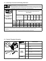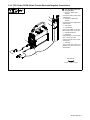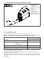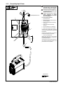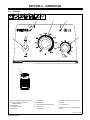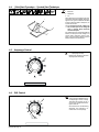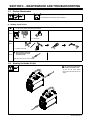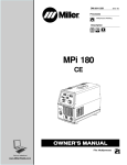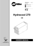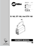
1
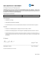
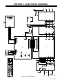
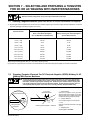
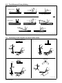
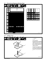
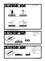
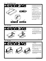
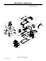
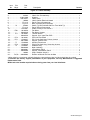
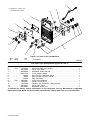
OM-244 324C 2013−01 Processes TIG (GTAW) Welding Stick (SMAW) Welding Description Arc Welding Power Source UNITOR UWI 202 CE TABLE OF CONTENTS SECTION 1 − SAFETY PRECAUTIONS - READ BEFORE USING . . . . . . . . . . . . . . . . . . . . . . . . . . . . . . . . . . . 1 1-1. Symbol Usage . . . . . . . . . . . . . . . . . . . . . . . . . . . . . . . . . . . . . . . . . . . . . . . . . . . . . . . . . . . . . . . . . . . . . . . . 1 1-2. Arc Welding Hazards . . . . . . . . . . . . . . . . . . . . . . . . . . . . . . . . . . . . . . . . . . . . . . . . . . . . . . . . . . . . . . . . . . 1 1-3. Additional Symbols For Installation, Operation, And Maintenance . . . . . . . . . . . . . . . . . . . . . . . . . . . . . 3 1-4. California Proposition 65 Warnings . . . . . . . . . . . . . . . . . . . . . . . . . . . . . . . . . . . . . . . . . . . . . . . . . . . . . . . 4 1-5. Principal Safety Standards . . . . . . . . . . . . . . . . . . . . . . . . . . . . . . . . . . . . . . . . . . . . . . . . . . . . . . . . . . . . . 4 1-6. EMF Information . . . . . . . . . . . . . . . . . . . . . . . . . . . . . . . . . . . . . . . . . . . . . . . . . . . . . . . . . . . . . . . . . . . . . . 4 SECTION 2 − DEFINITIONS . . . . . . . . . . . . . . . . . . . . . . . . . . . . . . . . . . . . . . . . . . . . . . . . . . . . . . . . . . . . . . . . . . . 5 2-1. Additional Safety Symbols And Definitions . . . . . . . . . . . . . . . . . . . . . . . . . . . . . . . . . . . . . . . . . . . . . . . . 5 2-2. Miscellaneous Symbols And Definitions . . . . . . . . . . . . . . . . . . . . . . . . . . . . . . . . . . . . . . . . . . . . . . . . . . . 7 SECTION 3 − INSTALLATION . . . . . . . . . . . . . . . . . . . . . . . . . . . . . . . . . . . . . . . . . . . . . . . . . . . . . . . . . . . . . . . . . . 8 3-1. Important Information Regarding CE Products (Sold Within The EU) . . . . . . . . . . . . . . . . . . . . . . . . . . . 8 3-2. Serial Number And Rating Label Location . . . . . . . . . . . . . . . . . . . . . . . . . . . . . . . . . . . . . . . . . . . . . . . . . 8 3-3. IP Rating . . . . . . . . . . . . . . . . . . . . . . . . . . . . . . . . . . . . . . . . . . . . . . . . . . . . . . . . . . . . . . . . . . . . . . . . . . . . 8 3-4. Specifications . . . . . . . . . . . . . . . . . . . . . . . . . . . . . . . . . . . . . . . . . . . . . . . . . . . . . . . . . . . . . . . . . . . . . . . . 8 3-5. Volt-Ampere Curves . . . . . . . . . . . . . . . . . . . . . . . . . . . . . . . . . . . . . . . . . . . . . . . . . . . . . . . . . . . . . . . . . . . 9 3-6. Duty Cycle And Overheating . . . . . . . . . . . . . . . . . . . . . . . . . . . . . . . . . . . . . . . . . . . . . . . . . . . . . . . . . . . . 10 3-7. Selecting A Location . . . . . . . . . . . . . . . . . . . . . . . . . . . . . . . . . . . . . . . . . . . . . . . . . . . . . . . . . . . . . . . . . . . 11 3-8. Weld Output Terminals And Selecting Cable Sizes* . . . . . . . . . . . . . . . . . . . . . . . . . . . . . . . . . . . . . . . . . 12 3-9. Remote 6 Receptacle Information . . . . . . . . . . . . . . . . . . . . . . . . . . . . . . . . . . . . . . . . . . . . . . . . . . . . . . . . 12 3-10. TIG Lift-Arc DCEN (Direct Current Electrode Negative) Connections . . . . . . . . . . . . . . . . . . . . . . . . . . 13 3-11. Stick DCEP (Direct Current Electrode Positive) Connections . . . . . . . . . . . . . . . . . . . . . . . . . . . . . . . . . 14 3-12. Electrical Service Guide . . . . . . . . . . . . . . . . . . . . . . . . . . . . . . . . . . . . . . . . . . . . . . . . . . . . . . . . . . . . . . . . 14 3-13. Connecting Input Power . . . . . . . . . . . . . . . . . . . . . . . . . . . . . . . . . . . . . . . . . . . . . . . . . . . . . . . . . . . . . . . . 15 SECTION 4 − OPERATION . . . . . . . . . . . . . . . . . . . . . . . . . . . . . . . . . . . . . . . . . . . . . . . . . . . . . . . . . . . . . . . . . . . . 16 4-1. Controls . . . . . . . . . . . . . . . . . . . . . . . . . . . . . . . . . . . . . . . . . . . . . . . . . . . . . . . . . . . . . . . . . . . . . . . . . . . . . 16 4-2. Process Control . . . . . . . . . . . . . . . . . . . . . . . . . . . . . . . . . . . . . . . . . . . . . . . . . . . . . . . . . . . . . . . . . . . . . . 17 4-3. Lift-Arc Start Procedure . . . . . . . . . . . . . . . . . . . . . . . . . . . . . . . . . . . . . . . . . . . . . . . . . . . . . . . . . . . . . . . . 17 4-4. Stick Start Procedure − Scratch Start Technique . . . . . . . . . . . . . . . . . . . . . . . . . . . . . . . . . . . . . . . . . . . 18 4-5. Amperage Control . . . . . . . . . . . . . . . . . . . . . . . . . . . . . . . . . . . . . . . . . . . . . . . . . . . . . . . . . . . . . . . . . . . . . 18 4-6. DIG Control . . . . . . . . . . . . . . . . . . . . . . . . . . . . . . . . . . . . . . . . . . . . . . . . . . . . . . . . . . . . . . . . . . . . . . . . . . 18 SECTION 5 − MAINTENANCE AND TROUBLESHOOTING . . . . . . . . . . . . . . . . . . . . . . . . . . . . . . . . . . . . . . . . 19 5-1. Routine Maintenance . . . . . . . . . . . . . . . . . . . . . . . . . . . . . . . . . . . . . . . . . . . . . . . . . . . . . . . . . . . . . . . . . . 19 5-2. Blowing Out Inside Of Unit . . . . . . . . . . . . . . . . . . . . . . . . . . . . . . . . . . . . . . . . . . . . . . . . . . . . . . . . . . . . . . 19 5-3. Troubleshooting . . . . . . . . . . . . . . . . . . . . . . . . . . . . . . . . . . . . . . . . . . . . . . . . . . . . . . . . . . . . . . . . . . . . . . 20 SECTION 6 − ELECTRICAL DIAGRAMS . . . . . . . . . . . . . . . . . . . . . . . . . . . . . . . . . . . . . . . . . . . . . . . . . . . . . . . . 21 SECTION 7 − SELECTING AND PREPARING A TUNGSTEN FOR DC OR AC WELDING WITH INVERTER MACHINES . . . . . . . . . . . . . . . . . . . . . . . . . . . . . . . . . . . . . . . . . . . . . . . . . . . . . . . . . . . . . . . . . . . . . . . . . . . . . . . . . . 22 7-1. Selecting Tungsten Electrode (Wear Clean Gloves To Prevent Contamination Of Tungsten) . . . . . . . 22 7-2. Preparing Tungsten Electrode For DC Electrode Negative (DCEN) Welding Or AC Welding With Inverter Machines . . . . . . . . . . . . . . . . . . . . . . . . . . . . . . . . . . . . . . . . . . . . . . . . . . . . . . . . . . . . . . . . . . . . . . . . . . . . 22 SECTION 8 − GUIDELINES FOR TIG WELDING (GTAW) . . . . . . . . . . . . . . . . . . . . . . . . . . . . . . . . . . . . . . . . . . 23 8-1. Positioning The Torch . . . . . . . . . . . . . . . . . . . . . . . . . . . . . . . . . . . . . . . . . . . . . . . . . . . . . . . . . . . . . . . . . . 23 8-2. Torch Movement During Welding . . . . . . . . . . . . . . . . . . . . . . . . . . . . . . . . . . . . . . . . . . . . . . . . . . . . . . . . 24 8-3. Positioning Torch Tungsten For Various Weld Joints . . . . . . . . . . . . . . . . . . . . . . . . . . . . . . . . . . . . . . . . 24 SECTION 9 − STICK WELDING (SMAW) GUIDELINES . . . . . . . . . . . . . . . . . . . . . . . . . . . . . . . . . . . . . . . . . . . . 25 SECTION 10 − PARTS LIST . . . . . . . . . . . . . . . . . . . . . . . . . . . . . . . . . . . . . . . . . . . . . . . . . . . . . . . . . . . . . . . . . . . 32 DECLARATION OF CONFORMITY for European Community (CE marked) products. ITW Welding Products Italy S.r.l Via Privata Iseo 6/E, 20098 San Giuliano M.se, (MI) Italy declares that the product(s) identified in this declaration conform to the essential requirements and provisions of the stated Council Directive(s) and Standard(s). Product/Apparatus Identification: Product Stock Number Unitor UWI 202 029 015 505 Council Directives: 2006/95/EC Low Voltage 2004/108/EC Electromagnetic Compatibility 2011/65/EU Restriction of the use of certain hazardous substances in electrical and electronic equipment Standards: IEC 609741 Arc Welding Equipment Welding Power Sources: edition 3, 200507. IEC 6097410 Arc Welding Equipment Electromagnetic Compatibility Requirements: edition 2.0, 200708. EN 50445:2008 Product family standard to demonstrate compliance of equipment for resistance welding, arc welding and allied processes with the basic restrictions related to human exposure to electromagnetic fields (0Hz300Hz) EU Signatory: January 2nd , 2013 ___________________________________________________________________________________ Massimigliano Lavarini Date of Declaration ELECTRONIC ENGINEER R&D TECH. SUPPORT 956 172 023 SECTION 1 − SAFETY PRECAUTIONS - READ BEFORE USING som 2011−10 7 Protect yourself and others from injury — read, follow, and save these important safety precautions and operating instructions. 1-1. Symbol Usage DANGER! − Indicates a hazardous situation which, if not avoided, will result in death or serious injury. The possible hazards are shown in the adjoining symbols or explained in the text. Indicates a hazardous situation which, if not avoided, could result in death or serious injury. The possible hazards are shown in the adjoining symbols or explained in the text. NOTICE − Indicates statements not related to personal injury. . Indicates special instructions. This group of symbols means Warning! Watch Out! ELECTRIC SHOCK, MOVING PARTS, and HOT PARTS hazards. Consult symbols and related instructions below for necessary actions to avoid the hazards. 1-2. Arc Welding Hazards The symbols shown below are used throughout this manual to call attention to and identify possible hazards. When you see the symbol, watch out, and follow the related instructions to avoid the hazard. The safety information given below is only a summary of the more complete safety information found in the Safety Standards listed in Section 1-5. Read and follow all Safety Standards. Only qualified persons should install, operate, maintain, and repair this unit. During operation, keep everybody, especially children, away. D Always verify the supply ground − check and be sure that input power cord ground wire is properly connected to ground terminal in disconnect box or that cord plug is connected to a properly grounded receptacle outlet. D When making input connections, attach proper grounding conductor first − double-check connections. D Keep cords dry, free of oil and grease, and protected from hot metal and sparks. D Frequently inspect input power cord for damage or bare wiring − replace cord immediately if damaged − bare wiring can kill. D Turn off all equipment when not in use. D Do not use worn, damaged, undersized, or poorly spliced cables. ELECTRIC SHOCK can kill. Touching live electrical parts can cause fatal shocks or severe burns. The electrode and work circuit is electrically live whenever the output is on. The input power circuit and machine internal circuits are also live when power is on. In semiautomatic or automatic wire welding, the wire, wire reel, drive roll housing, and all metal parts touching the welding wire are electrically live. Incorrectly installed or improperly grounded equipment is a hazard. D Do not touch live electrical parts. D Wear dry, hole-free insulating gloves and body protection. D Insulate yourself from work and ground using dry insulating mats or covers big enough to prevent any physical contact with the work or ground. D Do not use AC output in damp areas, if movement is confined, or if there is a danger of falling. D Use AC output ONLY if required for the welding process. D If AC output is required, use remote output control if present on unit. D Additional safety precautions are required when any of the following electrically hazardous conditions are present: in damp locations or while wearing wet clothing; on metal structures such as floors, gratings, or scaffolds; when in cramped positions such as sitting, kneeling, or lying; or when there is a high risk of unavoidable or accidental contact with the workpiece or ground. For these conditions, use the following equipment in order presented: 1) a semiautomatic DC constant voltage (wire) welder, 2) a DC manual (stick) welder, or 3) an AC welder with reduced open-circuit voltage. In most situations, use of a DC, constant voltage wire welder is recommended. And, do not work alone! D Disconnect input power or stop engine before installing or servicing this equipment. Lockout/tagout input power according to OSHA 29 CFR 1910.147 (see Safety Standards). D Properly install, ground, and operate this equipment according to its Owner’s Manual and national, state, and local codes. D Do not drape cables over your body. D If earth grounding of the workpiece is required, ground it directly with a separate cable. D Do not touch electrode if you are in contact with the work, ground, or another electrode from a different machine. D Do not touch electrode holders connected to two welding machines at the same time since double open-circuit voltage will be present. D Use only well-maintained equipment. Repair or replace damaged parts at once. Maintain unit according to manual. D Wear a safety harness if working above floor level. D Keep all panels and covers securely in place. D Clamp work cable with good metal-to-metal contact to workpiece or worktable as near the weld as practical. D Insulate work clamp when not connected to workpiece to prevent contact with any metal object. D Do not connect more than one electrode or work cable to any single weld output terminal. Disconnect cable for process not in use. SIGNIFICANT DC VOLTAGE exists in inverter welding power sources AFTER removal of input power. D Turn Off inverter, disconnect input power, and discharge input capacitors according to instructions in Maintenance Section before touching any parts. HOT PARTS can burn. D Do not touch hot parts bare handed. D Allow cooling period before working on equipment. D To handle hot parts, use proper tools and/or wear heavy, insulated welding gloves and clothing to prevent burns. OM-244 324 Page 1 FUMES AND GASES can be hazardous. Welding produces fumes and gases. Breathing these fumes and gases can be hazardous to your health. D Keep your head out of the fumes. Do not breathe the fumes. D If inside, ventilate the area and/or use local forced ventilation at the arc to remove welding fumes and gases. D If ventilation is poor, wear an approved air-supplied respirator. D Read and understand the Material Safety Data Sheets (MSDSs) and the manufacturer’s instructions for metals, consumables, coatings, cleaners, and degreasers. D Work in a confined space only if it is well ventilated, or while wearing an air-supplied respirator. Always have a trained watchperson nearby. Welding fumes and gases can displace air and lower the oxygen level causing injury or death. Be sure the breathing air is safe. D Do not weld in locations near degreasing, cleaning, or spraying operations. The heat and rays of the arc can react with vapors to form highly toxic and irritating gases. D Do not weld on coated metals, such as galvanized, lead, or cadmium plated steel, unless the coating is removed from the weld area, the area is well ventilated, and while wearing an air-supplied respirator. The coatings and any metals containing these elements can give off toxic fumes if welded. ARC RAYS can burn eyes and skin. Arc rays from the welding process produce intense visible and invisible (ultraviolet and infrared) rays that can burn eyes and skin. Sparks fly off from the weld. D Wear an approved welding helmet fitted with a proper shade of filter lenses to protect your face and eyes from arc rays and sparks when welding or watching (see ANSI Z49.1 and Z87.1 listed in Safety Standards). D Wear approved safety glasses with side shields under your helmet. D Use protective screens or barriers to protect others from flash, glare and sparks; warn others not to watch the arc. D Wear protective clothing made from durable, flame-resistant material (leather, heavy cotton, or wool) and foot protection. WELDING can cause fire or explosion. Welding on closed containers, such as tanks, drums, or pipes, can cause them to blow up. Sparks can fly off from the welding arc. The flying sparks, hot workpiece, and hot equipment can cause fires and burns. Accidental contact of electrode to metal objects can cause sparks, explosion, overheating, or fire. Check and be sure the area is safe before doing any welding. D Remove all flammables within 35 ft (10.7 m) of the welding arc. If this is not possible, tightly cover them with approved covers. D Do not weld where flying sparks can strike flammable material. D Protect yourself and others from flying sparks and hot metal. D Be alert that welding sparks and hot materials from welding can easily go through small cracks and openings to adjacent areas. D Watch for fire, and keep a fire extinguisher nearby. D Be aware that welding on a ceiling, floor, bulkhead, or partition can cause fire on the hidden side. D Do not weld on containers that have held combustibles, or on closed containers such as tanks, drums, or pipes unless they are properly prepared according to AWS F4.1 and AWS A6.0 (see Safety Standards). D Do not weld where the atmosphere may contain flammable dust, gas, or liquid vapors (such as gasoline). D Connect work cable to the work as close to the welding area as practical to prevent welding current from traveling long, possibly unknown paths and causing electric shock, sparks, and fire hazards. D Do not use welder to thaw frozen pipes. OM-244 324 Page 2 D Remove stick electrode from holder or cut off welding wire at contact tip when not in use. D Wear oil-free protective garments such as leather gloves, heavy shirt, cuffless trousers, high shoes, and a cap. D Remove any combustibles, such as a butane lighter or matches, from your person before doing any welding. D After completion of work, inspect area to ensure it is free of sparks, glowing embers, and flames. D Use only correct fuses or circuit breakers. Do not oversize or bypass them. D Follow requirements in OSHA 1910.252 (a) (2) (iv) and NFPA 51B for hot work and have a fire watcher and extinguisher nearby. FLYING METAL or DIRT can injure eyes. D Welding, chipping, wire brushing, and grinding cause sparks and flying metal. As welds cool, they can throw off slag. D Wear approved safety glasses with side shields even under your welding helmet. BUILDUP OF GAS can injure or kill. D Shut off compressed gas supply when not in use. D Always ventilate confined spaces or use approved air-supplied respirator. ELECTRIC AND MAGNETIC FIELDS (EMF) can affect Implanted Medical Devices. D Wearers of Pacemakers and other Implanted Medical Devices should keep away. D Implanted Medical Device wearers should consult their doctor and the device manufacturer before going near arc welding, spot welding, gouging, plasma arc cutting, or induction heating operations. NOISE can damage hearing. Noise from some processes or equipment can damage hearing. D Wear approved ear protection if noise level is high. CYLINDERS can explode if damaged. Compressed gas cylinders contain gas under high pressure. If damaged, a cylinder can explode. Since gas cylinders are normally part of the welding process, be sure to treat them carefully. D Protect compressed gas cylinders from excessive heat, mechanical shocks, physical damage, slag, open flames, sparks, and arcs. D Install cylinders in an upright position by securing to a stationary support or cylinder rack to prevent falling or tipping. D Keep cylinders away from any welding or other electrical circuits. D Never drape a welding torch over a gas cylinder. D Never allow a welding electrode to touch any cylinder. D Never weld on a pressurized cylinder − explosion will result. D Use only correct compressed gas cylinders, regulators, hoses, and fittings designed for the specific application; maintain them and associated parts in good condition. D Turn face away from valve outlet when opening cylinder valve. D Keep protective cap in place over valve except when cylinder is in use or connected for use. D Use the right equipment, correct procedures, and sufficient number of persons to lift and move cylinders. D Read and follow instructions on compressed gas cylinders, associated equipment, and Compressed Gas Association (CGA) publication P-1 listed in Safety Standards. 1-3. Additional Symbols For Installation, Operation, And Maintenance FIRE OR EXPLOSION hazard. BATTERY EXPLOSION can injure. D Do not install or place unit on, over, or near combustible surfaces. D Do not install unit near flammables. D Do not overload building wiring − be sure power supply system is properly sized, rated, and protected to handle this unit. D Do not use welder to charge batteries or jump start vehicles unless it has a battery charging feature designed for this purpose. MOVING PARTS can injure. D Keep away from moving parts such as fans. D Keep all doors, panels, covers, and guards closed and securely in place. FALLING EQUIPMENT can injure. D Use lifting eye to lift unit only, NOT running gear, gas cylinders, or any other accessories. D Use equipment of adequate capacity to lift and support unit. D If using lift forks to move unit, be sure forks are long enough to extend beyond opposite side of unit. D Keep equipment (cables and cords) away from moving vehicles when working from an aerial location. D Follow the guidelines in the Applications Manual for the Revised NIOSH Lifting Equation (Publication No. 94−110) when manually lifting heavy parts or equipment. OVERUSE can cause OVERHEATING D Allow cooling period; follow rated duty cycle. D Reduce current or reduce duty cycle before starting to weld again. D Do not block or filter airflow to unit. D Have only qualified persons remove doors, panels, covers, or guards for maintenance and troubleshooting as necessary. D Reinstall doors, panels, covers, or guards when maintenance is finished and before reconnecting input power. READ INSTRUCTIONS. D Read and follow all labels and the Owner’s Manual carefully before installing, operating, or servicing unit. Read the safety information at the beginning of the manual and in each section. D Use only genuine replacement parts from the manufacturer. D Perform maintenance and service according to the Owner’s Manuals, industry standards, and national, state, and local codes. H.F. RADIATION can cause interference. FLYING SPARKS can injure. D Wear a face shield to protect eyes and face. D Shape tungsten electrode only on grinder with proper guards in a safe location wearing proper face, hand, and body protection. D Sparks can cause fires — keep flammables away. STATIC (ESD) can damage PC boards. D D D D D Put on grounded wrist strap BEFORE handling boards or parts. D Use proper static-proof bags and boxes to store, move, or ship PC boards. ARC WELDING can cause interference. MOVING PARTS can injure. D Keep away from moving parts. D Keep away from pinch points such as drive rolls. WELDING WIRE can injure. D Do not press gun trigger until instructed to do so. D Do not point gun toward any part of the body, other people, or any metal when threading welding wire. D High-frequency (H.F.) can interfere with radio navigation, safety services, computers, and communications equipment. D Have only qualified persons familiar with electronic equipment perform this installation. The user is responsible for having a qualified electrician promptly correct any interference problem resulting from the installation. If notified by the FCC about interference, stop using the equipment at once. Have the installation regularly checked and maintained. Keep high-frequency source doors and panels tightly shut, keep spark gaps at correct setting, and use grounding and shielding to minimize the possibility of interference. D D D D D Electromagnetic energy can interfere with sensitive electronic equipment such as computers and computer-driven equipment such as robots. D Be sure all equipment in the welding area is electromagnetically compatible. To reduce possible interference, keep weld cables as short as possible, close together, and down low, such as on the floor. Locate welding operation 100 meters from any sensitive electronic equipment. Be sure this welding machine is installed and grounded according to this manual. If interference still occurs, the user must take extra measures such as moving the welding machine, using shielded cables, using line filters, or shielding the work area. OM-244 324 Page 3 1-4. California Proposition 65 Warnings Welding or cutting equipment produces fumes or gases which contain chemicals known to the State of California to cause birth defects and, in some cases, cancer. (California Health & Safety Code Section 25249.5 et seq.) This product contains chemicals, including lead, known to the state of California to cause cancer, birth defects, or other reproductive harm. Wash hands after use. 1-5. Principal Safety Standards Safety in Welding, Cutting, and Allied Processes, ANSI Standard Z49.1, is available as a free download from the American Welding Society at http://www.aws.org or purchased from Global Engineering Documents (phone: 1-877-413-5184, website: www.global.ihs.com). Safe Practices for the Preparation of Containers and Piping for Welding and Cutting, American Welding Society Standard AWS F4.1, from Global Engineering Documents (phone: 1-877-413-5184, website: www.global.ihs.com). Safe Practices for Welding and Cutting Containers that have Held Combustibles, American Welding Society Standard AWS A6.0, from Global Engineering Documents (phone: 1-877-413-5184, website: www.global.ihs.com). National Electrical Code, NFPA Standard 70, from National Fire Protection Association, Quincy, MA 02269 (phone: 1-800-344-3555, website: www.nfpa.org and www. sparky.org). Safe Handling of Compressed Gases in Cylinders, CGA Pamphlet P-1, from Compressed Gas Association, 14501 George Carter Way, Suite 103, Chantilly, VA 20151 (phone: 703-788-2700, website:www.cganet.com). Safety in Welding, Cutting, and Allied Processes, CSA Standard W117.2, from Canadian Standards Association, Standards Sales, 5060 Spectrum Way, Suite 100, Ontario, Canada L4W 5NS (phone: 800-463-6727, website: www.csa-international.org). Safe Practice For Occupational And Educational Eye And Face Protection, ANSI Standard Z87.1, from American National Standards Institute, 25 West 43rd Street, New York, NY 10036 (phone: 212-642-4900, website: www.ansi.org). Standard for Fire Prevention During Welding, Cutting, and Other Hot Work, NFPA Standard 51B, from National Fire Protection Association, Quincy, MA 02269 (phone: 1-800-344-3555, website: www.nfpa.org. OSHA, Occupational Safety and Health Standards for General Industry, Title 29, Code of Federal Regulations (CFR), Part 1910, Subpart Q, and Part 1926, Subpart J, from U.S. Government Printing Office, Superintendent of Documents, P.O. Box 371954, Pittsburgh, PA 15250-7954 (phone: 1-866-512-1800) (there are 10 OSHA Regional Offices— phone for Region 5, Chicago, is 312-353-2220, website: www.osha.gov). Applications Manual for the Revised NIOSH Lifting Equation, The National Institute for Occupational Safety and Health (NIOSH), 1600 Clifton Rd, Atlanta, GA 30333 (phone: 1-800-232-4636, website: www.cdc.gov/NIOSH). 1-6. EMF Information Electric current flowing through any conductor causes localized electric and magnetic fields (EMF). Welding current creates an EMF field around the welding circuit and welding equipment. EMF fields may interfere with some medical implants, e.g. pacemakers. Protective measures for persons wearing medical implants have to be taken. For example, restrict access for passers−by or conduct individual risk assessment for welders. All welders should use the following procedures in order to minimize exposure to EMF fields from the welding circuit: 1. Keep cables close together by twisting or taping them, or using a cable cover. 2. Do not place your body between welding cables. Arrange cables to one side and away from the operator. 3. Do not coil or drape cables around your body. OM-244 324 Page 4 4. Keep head and trunk as far away from the equipment in the welding circuit as possible. 5. Connect work clamp to workpiece as close to the weld as possible. 6. Do not work next to, sit or lean on the welding power source. 7. Do not weld whilst carrying the welding power source or wire feeder. About Implanted Medical Devices: Implanted Medical Device wearers should consult their doctor and the device manufacturer before performing or going near arc welding, spot welding, gouging, plasma arc cutting, or induction heating operations. If cleared by your doctor, then following the above procedures is recommended. SECTION 2 − DEFINITIONS 2-1. Additional Safety Symbols And Definitions Warning! Watch Out! There are possible hazards as shown by the symbols. Safe1 2012−05 Wear dry insulating gloves. Do not touch electrode with bare hand. Do not wear wet or damaged gloves. Safe2 2012−05 Protect yourself from electric shock by insulating yourself from work and ground. Safe3 2012−05 Disconnect input plug or power before working on machine. Safe5 2012−05 Keep your head out of the fumes. Safe6 2012−05 Use forced ventilation or local exhaust to remove the fumes. Safe8 2012−05 Use ventilating fan to remove fumes. Safe10 2012−05 Keep flammables away from welding. Do not weld near flammables. Safe12 2012−05 Welding sparks can cause fires. Have a fire extinguisher nearby, and have a watchperson ready to use it. Safe14 2012−05 Do not remove or paint over (cover) the label. Safe20 2012−05 OM-244 324 Page 5 When power is applied failed parts can explode or cause other parts to explode. Safe26 2012−05 Always wear long sleeves and button your collar when servicing unit. Safe28 2012−05 After taking proper precautions as shown, connect power to unit. Safe29 2012−05 Do not use one handle to lift or support unit. Safe31 2012−05 Do not weld on drums or any closed containers. Safe16 2012−05 Do not discard product (where applicable) with general waste. Reuse or recycle Waste Electrical and Electronic Equipment (WEEE) by disposing at a designated collection facility. Contact your local recycling office or your local distributor for further information. Safe37 2012−05 Disconnect input plug or power before working on machine. Safe30 2012−05 Wear hat and safety glasses. Use ear protection and button shirt collar. Use welding helmet with correct shade of filter. Wear complete body protection. Safe38 2012−05 Become trained and read the instructions before working on the machine or welding. Safe40 2012−05 = < 60 Always lift and support unit using both handles. Keep angle of lifting device less than 60 degrees. Use a proper cart to move unit. Safe44 2012−05 V V >60s OM-244 324 Page 6 V Hazardous voltage remains on input capacitors after power is turned off. Do not touch fully charged capacitors. Always wait 60 seconds after power is turned off before working on unit, OR check input capacitor voltage, and be sure it is near 0 before touching any parts. Safe42 2012−05 2-2. Miscellaneous Symbols And Definitions A Amperes Panel−Local V Volts Voltage Input Voltage Output Circuit Breaker Remote Protective Earth (Ground) Postflow Timer Preflow Timer On Off Positive Alternating Current Gas Input Gas Output Duty Cycle Direct Current Line Connection X U1 U0 Hz Primary Voltage IP Degree Of Protection Gas Tungsten Arc Welding (GTAW) Shielded Metal Arc Welding (SMAW) 3 Phase Static Frequency Converter-Transformer-Rectifier I1max Rated Maximum Supply Current Lift-Arc Start (GTAW) S Seconds Negative I2 U2 I1eff Rated Welding Current Conventional Load Voltage Maximum Effective Supply Current Rated No Load Voltage (Average) Pulse Background Amperage Initial Amperage Increase/Decrease Of Quantity Normal Trigger Operation (GTAW) Two-Step Trigger Operation (GTAW) Four-Step Trigger Operation (GTAW) Percent Hertz Recall From Memory Arc Force (DIG) HF Impulse Starting (GTAW) Final Slope Final Amperage Pulse Percent On Time Initial Slope Contactor Control (Stick) Pulser On-Off TIG Weld Amps And Peak Amps While Pulsing Pulse Frequency Background Amps Process Pulser Sequence Output Adjust S Suitable For Areas Of Increased Shock Hazard OM-244 324 Page 7 SECTION 3 − INSTALLATION 3-1. Important Information Regarding CE Products (Sold Within The EU) A. Information On Electromagnetic Fields (EMF) ! This equipment shall not be used by the general public as the EMF limits for the general public might be exceeded during welding. This equipment is built in accordance with EN 60974−1 and is intended to be used only in an occupational environment (where the general public access is prohibited or regulated in such a way as to be similar to occupational use) by an expert or an instructed person. Wire feeders and ancillary equipment (such as torches, liquid cooling systems and arc striking and stabilizing devices) as part of the welding circuit may not be a major contributor to the EMF. See the Owner’s Manuals for all components of the welding circuit for additional EMF exposure information. S S The EMF assessment on this equipment was conducted at 0.5 meter. At a distance of 1 meter the EMF exposure values were less than 20% of the permissible values. ce-emf 1 2010-10 B. Information On Electromagnetic Compatibility (EMC) ! This Class A equipment is not intended for use in residential locations where the electrical power is provided by the public low voltage supply system. There may be potential difficulties in ensuring electromagnetic compatibility in those locations, due to conducted as well as radiated disturbances. ! This equipment does not comply with IEC 61000−3−12. If it is connected to a public low voltage system, it is the responsibility of the installer or user of the equipment to ensure, by consultation with the distribution network operator if necessary, that the equipment may be connected. ce-emc 2 2010-10 3-2. Serial Number And Rating Label Location The serial number and rating information for the power source is located on the rear of the machine. Use the rating labels to determine input power requirements and/or rated output. For future reference, write serial number in space provided on back cover of this manual. 3-3. IP Rating IP Rating: 23. This equipment is designed for outdoor use. It may be stored, but is not intended to be used outside during precipitation unless sheltered. Operating Temperature Range: 14F (-10 C) to 104 F (40 C). Ratings were developed at an ambient temperature of 20 C to 25 C. 3-4. Specifications Welding Process Rated Output Stick 200 A @ 28 VDC, 40% Duty Cycle TIG 200 A @ 18 VDC, 40% Duty Cycle OM-244 324 Page 8 Welding Amperage Range 5 − 200 Max. Open-Circuit Voltage (U0) Amperes Input At Rated Output, 50/60Hz 380 400 440 13.5 12.8 11.5 KVA KW Dimensions 8.86 6.51 Length: 17-1/4 in. (438 mm) Width: 7-9/16 in. (192 mm) 68 VDC 8.7 8.3 7.5 5.73 4.2 Height: 13-3/8 in. (333 mm) Weight 28 lb (12.5 Kg) 3-5. Volt-Ampere Curves Volt-ampere curves show minimum and maximum voltage and amperage output capabilities of welding power source. Curves of other settings fall between curves shown. 230 VAC Input 100 80 TIG/Stick Max Volts 60 40 TIG Min 20 Stick Min 0 0 50 100 Amperes 150 200 250 OM-244 324 Page 9 3-6. Duty Cycle And Overheating Duty Cycle is percentage of 10 minutes that unit can weld at rated load without overheating. If unit overheats, output stops and cooling fan runs. Wait fifteen minutes for unit to cool. Reduce amperage or voltage, or duty cycle before welding. NOTICE − Exceeding duty cycle can damage unit and void warranty. 250 STICK/TIG OUTPUT AMPERES 200 150 100 50 0 50 10 100 % DUTY CYCLE 4 Minutes Welding 6 Minutes Resting Overheating A or V 0 15 Minutes OM-244 324 Page 10 OR Reduce Duty Cycle 3-7. Selecting A Location 1 Line Disconnect Device Locate unit near correct input power supply. ! Location And Airflow Special installation may be required where gasoline or volatile liquids are present − see NEC Article 511 or CEC Section 20. 1 18 in. (460 mm) 18 in. (460 mm) OM-244 324 Page 11 3-8. Weld Output Terminals And Selecting Cable Sizes* ! ARC WELDING can cause Electromagnetic Interference. To reduce possible interference, keep weld cables as short as possible, close together, and down low, such as on the floor. Locate welding operation 100 meters from any sensitive electronic equipment. Be sure this welding machine is installed and grounded according to this manual. If interference still occurs, the user must take extra measures such as moving the welding machine, using shielded cables, using line filters, or shielding the work area. Weld Cable Size** and Total Cable (Copper) Length in Weld Circuit Not Exceeding*** Weld Output Terminals ! ! Turn off power before connecting to weld output terminals. 30 m (100 ft) or Less Do not use worn, damaged, undersized, or poorly spliced cables. * This 45 m (150 ft) 60 m (200 ft) 70 m (250 ft) 90 m (300 ft) 105 m (350 ft) 120 m (400 ft) Welding Amperes 10 − 60% Duty Cycle 60 − 100% Duty Cycle 100 20 (4) 20 (4) 20 (4) 30 (3) 35 (2) 50 (1) 60 (1/0) 60 (1/0) 150 30 (3) 30 (3) 35 (2) 50 (1) 60 (1/0) 70 (2/0) 95 (3/0) 95 (3/0) 200 30 (3) 35 (2) 50 (1) 60 (1/0) 70 (2/0) 95 (3/0) 120 (4/0) 120 (4/0) 10 − 100% Duty Cycle chart is a general guideline and may not suit all applications. If cable overheats, use next size larger cable. **Weld cable size is mm2 based on either a 4 volts or less drop or a current density of at least 300 circular mils per ampere. ( ) = AWG S-0007-F ***For distances longer than those shown in this guide, call a factory applications representative at 920-735-4505. 3-9. Remote 6 Receptacle Information 6 REMOTE OUTPUT CONTROL CHASSIS OM-244 324 Page 12 Socket* Socket Information 1 Not used 2 Not used 3 Output to remote control; +10 volts DC output to remote control. 4 0 to +10 volts DC input command signal from remote control. 5 Remote control circuit common. 6 Chassis common. 3-10. TIG Lift-Arc DCEN (Direct Current Electrode Negative) Connections 5 4 ! Turn off power before making connections. 1 Positive (+) Weld Output Terminal Connect work lead to positive weld output terminal. 6 2 3 Connect TIG torch to negative weld output terminal. 3 4 Negative (−) Weld Output Terminal Gas Cylinder Cylinder Valve Open valve slightly so gas flow blows dirt from valve. Close valve. 5 6 Regulator/Flowmeter Flow Adjust Typical flow rate is 15 cubic feet per hour (7.1 liters per minute). 1 Connect torch gas hose to regulator/flowmeter. 7 Gas Valve Valve controls gas preflow and postflow. Open valve on torch just before welding. 7 2 Tools Needed: 11/16 in., 1-1/8 in. (21 mm) OM-244 324 Page 13 3-11. Stick DCEP (Direct Current Electrode Positive) Connections ! Turn off power before making connections. 1 Negative (−) Weld Output Terminal Connect work lead to negative weld output terminal. 2 Positive (+) Weld Output Terminal Connect electrode holder to positive weld output terminal. 3 Remote 14 Receptacle If desired, connect remote control to Remote 14 receptacle (see Section 3-9). 2 1 3-12. Electrical Service Guide . Actual input voltage cannot exceed -10% of minimum, or +10% of maximum input voltages indicated in table. Failure to follow these electrical service guide recommendations could create an electric shock or fire hazard. These recommendations are for a dedicated branch circuit sized for the rated output and duty cycle of the welding power source. Three-Phase, 40% Duty Cycle 380−440 +/− 10% Input Voltage (V) 13.5−11.5 Input Amperes (A) At Rated Output Max Recommended Standard Fuse Rating In Amperes 1 Time Delay 2 Normal Operating 10 3 Min Input Conductor Size In AWG 4 Max Recommended Input Conductor Length In Feet (Meters) Min Grounding Conductor Size In AWG 4 20 13 (2.63 mm2) (3.5) 13 (2.63 mm2) Reference: 2011 National Electrical Code (NEC) (including article 630) 1 If a circuit breaker is used in place of a fuse, choose a circuit breaker with time-current curves comparable to the recommended fuse. 2 “Time-Delay” fuses are UL class “RK5” . See UL 248. 3 “Normal Operating” (general purpose - no intentional delay) fuses are UL class “K5” (up to and including 60 amps), and UL class “H” ( 65 amps and above). 4 Conductor data in this section specifies conductor size (excluding flexible cord or cable) between the panelboard and the equipment per NEC Table 310.15(B)(16). If a flexible cord or cable is used, minimum conductor size may increase. See NEC Table 400.5(A) for flexible cord and cable requirements. OM-244 324 Page 14 3-13. Connecting Input Power 3 ! Installation must meet all National and Local Codes − have only qualified persons make this installation. ! Disconnect and lockout/tagout input power before connecting input conductors from unit. ! Always connect green or green/ yellow conductor to supply grounding terminal first, and never to a line terminal. = GND/PE Earth Ground For Three-Phase Operation 4 1 2 3 7 4 5 6 2 Input Power Cord. Disconnect Device (switch shown in the OFF position) Green Or Green/Yellow Grounding Conductor Disconnect Device Grounding Terminal Input Conductors (L1, L2 And L3) Disconnect Device Line Terminals Connect green or green/yellow grounding conductor to disconnect device grounding terminal first. Connect input conductors L1, L2, and L3 to disconnect device line terminals. 7 L1 3 L2 L3 6 5 Over-Current Protection Select type and size of over-current protection using Section 3-12 (fused disconnect switch shown). Close and secure door on disconnect device. Remove lockout/tagout device, and place switch in the On position. 1 Tools Needed: OM-244 324 Page 15 SECTION 4 − OPERATION 4-1. Controls 5 2 4 3 1 UWI 202 6 Green on nameplate indicates a TIG function, Gray indicates a Stick function. 1 Process Controls See Section 4-2. 2 Amperage Control See Section 4-5. 3 DIG Control See Section 4-6. 4 High Temperature Shutdown Light See Section 3-6. 5 Power On Light The power on light turns on when power is turned on. 6 Power Switch Use switch to turn unit and indicator light On/Off. 202 722-A / 802 889 OM-244 324 Page 16 4-2. Process Control 1 Process Control Use the Process control to select the Stick process (up), or the TIG Lift Arc process (down). 1 Stick (SMAW) - This is a DCEP (direct current electrode positive) process. Make connections according to Section 3-11. TIG Lift-Arct - This is a DCEN (direct current electrode negative) process in which the electrode must come in contact with the work piece to initiate an arc (see Section 4-3). Make connections according to Section 3-10. 4-3. Lift-Arc Start Procedure Lift-Arc Start With Lift-Arct selected, start arc as follows: Lift-Arc Start Method 1 “Touch” 1−2 Seconds 2 1 TIG Electrode 2 Workpiece Turn gas on. Touch tungsten electrode to workpiece at weld start point. Hold electrode to workpiece for 1-2 seconds, and slowly lift electrode. Arc is formed when electrode is lifted. Normal open-circuit voltage is not present before tungsten electrode touches workpiece; only a low sensing voltage is present between electrode and workpiece. The solid-state output contactor does not energize until after electrode is touching workpiece. This allows electrode to touch workpiece without overheating, sticking, or getting contaminated. Application: Lift-Arc is used for the DCEN GTAW process when HF Start method is not permitted, or to replace the scratch method. Do NOT Strike Like A Match! OM-244 324 Page 17 4-4. Stick Start Procedure − Scratch Start Technique With Stick selected, start arc as follows: 1 2 3 Electrode Workpiece Arc Drag electrode across workpiece like striking a match; lift electrode slightly after touching work. If arc goes out electrode was lifted to high. If electrode sticks to workpiece, use a quick twist to free it. 1 2 3 Y For models with stock number 907 220, normal open-circuit voltage (80 volts) is present before electrode touches workpiece. For models with stock numbers 907 036 and 907 037, normal open-circuit voltage is not present before electrode touches workpiece; only a low sensing voltage is present between electrode and workpiece. 4-5. Amperage Control 1 1 A (Amperage Control) Rotate knob clockwise to increase amperage (Min-200 amps). Min 4-6. DIG Control 1 1 DIG Control Control increases SMAW short-circuit amperage at low arc voltage. This allows the operator to use a very short arc length without sticking the electrode. Set control at 0 for normal welding amperage. Turn clockwise to increase short-circuit amperage. OM-244 324 Page 18 SECTION 5 − MAINTENANCE AND TROUBLESHOOTING 5-1. Routine Maintenance ! Disconnect power before maintaining. . Maintain more often during severe conditions. A. Welding Power Source n = Check Z = Change ~ = Clean * To be done by Factory Authorized Service Agent = Repair l = Replace Every 3 Months nl Labels n l Gas Hoses Every 3 Months n lCables And Cords Every 6 Months ! Do not remove case when blowing out inside of unit (see Section 5-2) . ~:Durning heavy service, clean monthly. 5-2. Blowing Out Inside Of Unit ! Do not remove case when blowing out inside of unit. To blow out unit, direct airflow through front and back louvers as shown. OM-244 324 Page 19 5-3. Troubleshooting Trouble No weld output; unit completely inoperative. Remedy Place line disconnect switch in On position (see Section 3-13). Check and replace line fuse(s), if necessary, or reset circuit breaker (see Section 3-13). Check for proper input power connections (see Section 3-13). No weld output; Output LED on. Input voltage outside acceptable range of variation (see Section 3-12). No weld output; Overtemp LED on. Unit overheated. Allow unit to cool with fan On (see Sections 3-6). Erratic or improper weld output. Use proper size and type of weld cable (see Section 3-8). Clean and tighten all weld connections (see Section 3-8). Fan not operating. Check for and remove anything blocking fan movement. Have Factory Authorized Service Agent check fan motor. Wandering arc Use proper size tungsten (see Section 7). Use properly prepared tungsten (see Section 7). Reduce gas flow rate (see Section 3-10). Tungsten electrode oxidizing and not re- Shield weld zone from drafts. maining bright after conclusion of weld. Allow adequate postflow time to shield tungsten while it cools, after welding stops. Check and tighten all gas fittings (see Section 3-10). Water in torch. Refer to torch manual. OM-244 324 Page 20 SECTION 6 − ELECTRICAL DIAGRAMS L1 L2 P GND J1 S1 440V 220V 0V J2 J7 J6 J5 J4 T1 1 1 1 20V 0V 1 1 1 1 1 J1 1 J5 1 2 CON2 J5 J1 J2 J3 J3 PC1 PC3 J4 CURRENT R1 I II III DL1 DL4 J8 J9 J10 ON ARC TIG TEMP. SW1 R2 ARCFORCE/SLOPE T T2 1 2 3 4 5 6 7 8 9 10 J1 1 1 1 1 J7 J4 J3 J8 J11 1 PC2 HS1 J2 J10 J6 SHUNT R6 1 1 1 Z1 R1 R2 NEGATIVE POSITIVE 956 142 658 Figure 6-1. Circuit Diagram L3 GND Z1 FM 1 2 3 4 5 6 REMOTE 1 2 3 4 5 6 1 2 3 4 5 6 7 8 9 10 11 12 13 14 1 2 3 4 5 6 7 8 9 10 11 12 13 14 1 2 3 4 5 6 7 8 OM-2226 Page 21 SECTION 7 − SELECTING AND PREPARING A TUNGSTEN FOR DC OR AC WELDING WITH INVERTER MACHINES gtaw_Inverter_2011-06 Whenever possible and practical, use DC weld output instead of AC weld output. 7-1. Selecting Tungsten Electrode (Wear Clean Gloves To Prevent Contamination Of Tungsten ) . Not all tungsten electrode manufacturers use the same colors to identify tungsten type. Contact the tungsten electrode manufacturer or reference the product packaging to identify the tungsten you are using. Amperage Range - Gas Type - Polarity Electrode Diameter (DCEN) − Argon AC − Argon Direct Current Electrode Negative Balance Control @ 65% Electrode Negative (For Use With Aluminum) (For Use With Mild Or Stainless Steel) 2% Ceria, 1.5% Lanthanum, Or 2% Thorium Alloy Tungstens .010 in. (1 mm) Up to 25 Up to 20 .020 in. (1 mm) 15-40 15-35 .040 in. (1 mm) 25-85 20-80 1/16 in. (1.6 mm) 50-160 50-150 3/32 in. (2.4 mm) 130-250 135-235 1/8 in. (3.2 mm) 250-400 225-360 5/32 in. (4.0 mm) 400-500 300-450 3/16 in (4.8 mm) 500-750 400-500 1/4 in. (6.4 mm) 750-1000 600-800 Typical argon shielding gas flow rates are 11 to 35 CFH (cubic feet per hour). Figures listed are a guide and are a composite of recommendations from American Welding Society (AWS) and electrode manufacturers. 7-2. Preparing Tungsten Electrode For DC Electrode Negative (DCEN) Welding Or AC Welding With Inverter Machines Grinding the tungsten electrode produces dust and flying sparks which can cause injury and start fires. Use local exhaust (forced ventilation) at the grinder or wear an approved respirator. Read MSDS for safety information. Consider using tungsten containing ceria, lanthana, or yttria instead of thoria. Grinding dust from thoriated electrodes contains low-level radioactive material. Properly dispose of grinder dust in an environmentally safe way. Wear proper face, hand, and body protection. Keep flammables away. Radial Grinding Causes Wandering Arc 2-1/2 Times Electrode Diameter 1 3 2 1 Grinding Wheel Grind end of tungsten on fine grit, hard abrasive wheel before welding. Do not use wheel for other jobs or tungsten can become contaminated causing lower weld quality. 2 Tungsten Electrode A 2% ceriated tungsten is recommended. Wrong Tungsten Preparation 4 Ideal Tungsten Preparation − Stable Arc 3 Flat Diameter of this flat determines amperage capacity. 4 Straight Ground Grind lengthwise, not radial. OM-244 324 Page 22 SECTION 8 − GUIDELINES FOR TIG WELDING (GTAW) 8-1. Positioning The Torch ! Grinding the tungsten electrode produces dust and flying sparks which can cause injury and start fires. Use local exhaust (forced ventilation) at the grinder or wear an approved respirator. Read MSDS for safety information. Consider using cerium or lanthanum based tungsten instead of thoriated. Thorium dust contains low-level radioactive material. Properly dispose of grinder dust in an environmentally safe way. Wear proper face, hand, and body protection. Keep flammables away. 1 Workpiece 3 2 4 90 Make sure workpiece is clean before welding. 1 2 Work Clamp Place as close to the weld as possible. 3 4 5 6 10−15 4 5 6 10−25 5 6 Torch Filler Rod (If Applicable) Gas Cup Tungsten Electrode Select and prepare tungsten according to Section 7. Guidelines: The inside diameter of the gas cup should be at least three times the tungsten diameter to provide adequate shielding gas coverage. (For example, if tungsten is 1/16 in. diameter, gas cup should be a minimum of 3/16 in. diameter. Tungsten extension is the distance the tungsten extends out gas cup of torch. 1/16 in. 3/16 in. Bottom View Of Gas Cup The tungsten extension should be no greater than the inside diameter of the gas cup. Arc length is the distance from the tungsten to the workpiece. Ref. ST-161 892 OM-244 324 Page 23 8-2. Torch Movement During Welding Tungsten Without Filler Rod 75 Welding direction Form pool Tilt torch Move torch to front of pool. Repeat process. Tungsten With Filler Rod 75 Welding direction Form pool 15 Tilt torch Remove rod Add filler metal Move torch to front of pool. Repeat process. ST-162 002-B 8-3. Positioning Torch Tungsten For Various Weld Joints “T” Joint Butt Weld And Stringer Bead 20 90 70 75 20 10 15 Corner Joint Lap Joint 20-40 90 75 75 15 15 30 ST-162 003 / S-0792 OM-244 324 Page 24 SECTION 9 − STICK WELDING (SMAW) GUIDELINES 9-1. Stick Welding Procedure ! Weld current starts when electrode touches workpiece. ! Weld current can damage electronic parts in vehicles. Disconnect both battery cables before welding on a vehicle. Place work clamp as close to the weld as possible. Equipment Needed: Tools Needed: . Always wear appropriate per1 Constant Current Welding Power Source sonal protective clothing. Workpiece Make sure workpiece is clean before welding. 2 3 Work Clamp Electrode A small diameter electrode requires less current than a large one. Follow electrode manufacturer’s instructions when setting weld amperage (see Section 9-2). 4 5 6 5 4 Insulated Electrode Holder Electrode Holder Position Arc Length Arc length is the distance from the electrode to the workpiece. A short arc with correct amperage will give a sharp, crackling sound. 2 7 3 Slag Use a chipping hammer and wire brush to remove slag. Remove slag and check weld bead before making another weld pass. 6 1 7 stick 2010−02 − 151 593 OM-244 324 Page 25 6013 7014 7018 7024 Ni-Cl 308L ALL DEEP EP ALL DEEP 6013 EP,EN ALL LOW GENERAL 7014 EP,EN ALL MED 7018 EP ALL MED SMOOTH, EASY, FAST LOW HYDROGEN, STRONG 7024 EP,EN NI-CL EP FLAT HORIZ FILLET ALL 308L EP ALL USAGE EP 6011 AC PENETRATION 3/32 1/8 5/32 3/16 7/32 1/4 1/16 5/64 3/32 1/8 5/32 3/16 7/32 1/4 3/32 1/8 5/32 3/16 7/32 1/4 3/32 1/8 5/32 3/16 7/32 1/4 3/32 1/8 5/32 3/16 7/32 1/4 3/32 1/8 5/32 3/16 3/32 1/8 5/32 DC* 6010 ELECTRODE 450 400 350 300 250 200 150 POSITION 6010 & 6011 100 50 DIAMETER AMPERAGE RANGE Electrode and Amperage Selection Chart ELECTRODE 9-2. MIN. PREP, ROUGH HIGH SPATTER LOW SMOOTH, EASY, FASTER LOW CAST IRON LOW STAINLESS *EP = ELECTRODE POSITIVE (REVERSE POLARITY) EN = ELECTRODE NEGATIVE (STRAIGHT POLARITY) Ref. S-087 985-A 9-3. Striking an Arc 1 2 3 Electrode Workpiece Arc Scratch Technique 1 2 Drag electrode across workpiece like striking a match; lift electrode slightly after touching work. If arc goes out, electrode was lifted too high. If electrode sticks to workpiece, use a quick twist to free it. Tapping Technique Bring electrode straight down to workpiece; then lift slightly to start arc. If arc goes out, electrode was lifted too high. If electrode sticks to workpiece, use a quick twist to free it. 3 1 2 3 S-0049 / S-0050 OM-244 324 Page 26 9-4. Positioning Electrode Holder 1 2 End View Of Work Angle Side View Of Electrode Angle 1 10-30 90 2 90 Groove Welds 10-30 45 1 2 45 Fillet Welds S-0060 9-5. Poor Weld Bead Characteristics 1 2 3 4 5 Large Spatter Deposits Rough, Uneven Bead Slight Crater During Welding Bad Overlap Poor Penetration 4 2 3 5 1 S-0053-A 9-6. Good Weld Bead Characteristics 1 2 3 Fine Spatter Uniform Bead Moderate Crater During Welding Weld a new bead or layer for each 1/8 in. (3.2 mm) thickness in metals being welded. 2 3 4 5 4 5 No Overlap Good Penetration into Base Metal 1 S-0052-B OM-244 324 Page 27 9-7. Conditions That Affect Weld Bead Shape . Weld bead shape is affected by electrode angle, arc length, travel speed, and thickness of base metal. Angle Too Small Correct Angle 10 - 30 Angle Too Large Electrode Angle Drag Spatter Arc Length Too Short Normal Too Long Slow Normal Fast Travel Speed S-0061 9-8. Electrode Movement During Welding . Normally, 2 1 1 2 3 3 a single stringer bead is satisfactory for most narrow groove weld joints; however, for wide groove weld joints or bridging across gaps, a weave bead or multiple stringer beads work better. Stringer Bead − Steady Movement Along Seam Weave Bead − Side to Side Movement Along Seam Weave Patterns Use weave patterns to cover a wide area in one pass of the electrode. Do not let weave width exceed 2-1/2 times diameter of electrode. S-0054-A OM-244 324 Page 28 9-9. Groove (Butt) Joints 1 Tack Welds Prevent edges of joint from drawing together ahead of electrode by tack welding the materials in position before final weld. 1 2 2 Square Groove Weld Good for materials up to 3/16 in. (5 mm) thick. 3 1/16 in. (1.6 mm) Single V-Groove Weld Good for materials 3/16 − 3/4 in. (5-19 mm) thick. Cut bevel with oxyacetylene or plasma cutting equipment. Remove scale from material after cutting. A grinder can also be used to prepare bevels. 30 Create 30 degree angle of bevel on materials in V-groove welding. 4 Good for materials thicker than 3/16 in. (5 mm). 4 3 Double V-Groove Weld S-0062 9-10. Lap Joint 1 2 Electrode Single-Layer Fillet Weld Move electrode in circular motion. 3 30 Or Less 30 Or Less 1 1 Multi-Layer Fillet Weld Weld a second layer when a heavier fillet is needed. Remove slag before making another weld pass. Weld both sides of joint for maximum strength. 3 2 S-0063 / S-0064 9-11. Tee Joint 1 2 Electrode Fillet Weld Keep arc short and move at definite rate of speed. Hold electrode as shown to provide fusion into the corner. Square edge of the weld surface. For maximum strength weld both sides of upright section. 1 2 45 Or Less 1 2 3 3 Multi-Layer Deposits Weld a second layer when a heavier fillet is needed. Use any of the weaving patterns shown in Section 9-8. Remove slag before making another weld pass. S-0060 / S-0058-A / S-0061 OM-244 324 Page 29 9-12. Weld Test 1 2 3 Vise Weld Joint Hammer Strike weld joint in direction shown. A good weld bends over but does not break. 3 3 2 To 3 in. (51-76 mm) 1/4 in. (6.4 mm) 2 1 2 To 3 in. (51-76 mm) 2 1 S-0057-B 9-13. Troubleshooting Porosity − small cavities or holes resulting from gas pockets in weld metal. Possible Causes Corrective Actions Arc length too long. Reduce arc length. Damp electrode. Use dry electrode. Workpiece dirty. Remove all grease, oil, moisture, rust, paint, coatings, slag, and dirt from work surface before welding. Excessive Spatter − scattering of molten metal particles that cool to solid form near weld bead. Possible Causes Corrective Actions Amperage too high for electrode. Decrease amperage or select larger electrode. Arc length too long or voltage too high. Reduce arc length or voltage. Incomplete Fusion − failure of weld metal to fuse completely with base metal or a preceeding weld bead. Possible Causes Corrective Actions Insufficient heat input. Increase amperage. Select larger electrode and increase amperage. Improper welding technique. Place stringer bead in proper location(s) at joint during welding. Adjust work angle or widen groove to access bottom during welding. Momentarily hold arc on groove side walls when using weaving technique. Keep arc on leading edge of weld puddle. Workpiece dirty. OM-244 324 Page 30 Remove all grease, oil, moisture, rust, paint, coatings, slag, and dirt from work surface before welding. Lack Of Penetration − shallow fusion between weld metal and base metal. Lack of Penetration Good Penetration Possible Causes Corrective Actions Improper joint preparation. Material too thick. Joint preparation and design must provide access to bottom of groove. Improper weld technique. Keep arc on leading edge of weld puddle. Insufficient heat input. Increase amperage. Select larger electrode and increase amperage. Reduce travel speed. Excessive Penetration − weld metal melting through base metal and hanging underneath weld. Excessive Penetration Good Penetration Possible Causes Corrective Actions Excessive heat input. Select lower amperage. Use smaller electrode. Increase and/or maintain steady travel speed. Burn-Through − weld metal melting completely through base metal resulting in holes where no metal remains. Possible Causes Corrective Actions Excessive heat input. Select lower amperage. Use smaller electrode. Increase and/or maintain steady travel speed. Waviness Of Bead − weld metal that is not parallel and does not cover joint formed by base metal. Possible Causes Corrective Actions Unsteady hand. Use two hands. Practice technique. Distortion − contraction of weld metal during welding that forces base metal to move. Base metal moves in the direction of the weld bead. Possible Causes Corrective Actions Excessive heat input. Use restraint (clamp) to hold base metal in position. Make tack welds along joint before starting welding operation. Select lower amperage for electrode. Increase travel speed. Weld in small segments and allow cooling between welds. OM-244 324 Page 31 SECTION 10 − PARTS LIST . Hardware is common and not available unless listed. 16 15 17 24 14 1 13 2 12 11 18 19 20 25 21 22 10 23 Fig. 10-3 3 4 5 9 8 Fig. 10-4 7 Fig. 10-2 6 Figure 10-1. Main Assembly OM-244 324 Page 32 Item No. Dia. Mkgs. Part No. Description Quantity Figure 10-1. Main Assembly 1 . . . . . . . . . . . . . . . . . . 208015 2 . . . . . . . . . . . . . . . . . . 207233 3 . . . . . . . . . . . . . . +156121038 4 . . . . . . . . . . . . . . V56142107 5 . . . . . . . . . . . . . . . . . . 185836 6 . . . . . . . . . . . . . . . . . Fig 10-2 7 . . . . . . . . . . . . . . . . . Fig 10-4 8 . . . . . . . . S1 . . . . . . 244920 9 . . . . . . . . . . . . . . . . . Fig 10-3 10 . . . . . . . . . . . . . . . 57014221 11 . . . . . . FM1 . . . . 56126076 12 . . . . . . . . . . . . . . 156005138 13 . . . . . . TP1 . . . . 56159027 14 . . . . . . . . . . . . . . 156005139 15 . . . . . . PC4 . . . . 56130021 16 . . . . . . PC1 . . . . 57084137 17 . . . . . . . . . . . . . . 156118055 18 . . . . . . . T1 . . . . 57059006 19 . . . . . . PC2 . . . . 57084138 20 . . . . . . . Z1 . . . . 57059007 21 . . . . . . . . . . . . . . 756084029 22 . . . . . . . . . . . . . . 156006061 23 . . . . . . . . . . . . . . 756005028 24 . . . . . . . . . . . . . . . . . 195663 25 . . . . . R1,R2 . . 056059283 .... .... .... .... .... .... .... .... .... .... .... .... .... .... .... .... .... .... .... .... .... .... .... .... .... Handle . . . . . . . . . . . . . . . . . . . . . . . . . . . . . . . . . . . . . . . . . . . . . . . . . . . . . . . Label, Gen. Precautionary . . . . . . . . . . . . . . . . . . . . . . . . . . . . . . . . . . . . . . . Wrapper . . . . . . . . . . . . . . . . . . . . . . . . . . . . . . . . . . . . . . . . . . . . . . . . . . . . . . . Label, Unitor . . . . . . . . . . . . . . . . . . . . . . . . . . . . . . . . . . . . . . . . . . . . . . . . . . Label, Caution Electrical Hazard . . . . . . . . . . . . . . . . . . . . . . . . . . . . . . . . . Panel, Front w/Components . . . . . . . . . . . . . . . . . . . . . . . . . . . . . . . . . . . . . . Base, Assembly w/Components . . . . . . . . . . . . . . . . . . . . . . . . . . . . . . . . . . Switch, Tgl 3Pst 40A 600 VAC Scr Term Wide Tgl . . . . . . . . . . . . . . . . . . Panel, Rear w/Components . . . . . . . . . . . . . . . . . . . . . . . . . . . . . . . . . . . . . Cable, Primary 4 Core 2.5mm 2 . . . . . . . . . . . . . . . . . . . . . . . . . . . . . . . . . . Fan Motor . . . . . . . . . . . . . . . . . . . . . . . . . . . . . . . . . . . . . . . . . . . . . . . . . . . . . Fan Motor, Support . . . . . . . . . . . . . . . . . . . . . . . . . . . . . . . . . . . . . . . . . . . . . Thermal Switch . . . . . . . . . . . . . . . . . . . . . . . . . . . . . . . . . . . . . . . . . . . . . . . . . Support, Line Input Filter PCB . . . . . . . . . . . . . . . . . . . . . . . . . . . . . . . . . . . PC4 Line Filter Board . . . . . . . . . . . . . . . . . . . . . . . . . . . . . . . . . . . . . . . . . . . PC1 Circuit Card Assy, Primary Inverter . . . . . . . . . . . . . . . . . . . . . . . . . . . Support, Inverter PCB . . . . . . . . . . . . . . . . . . . . . . . . . . . . . . . . . . . . . . . . . . . Auxiliary Transformer . . . . . . . . . . . . . . . . . . . . . . . . . . . . . . . . . . . . . . . . . . . PC2 Circuit Card Assy, Secondary Inverter . . . . . . . . . . . . . . . . . . . . . . . . . Stabilizer Assy . . . . . . . . . . . . . . . . . . . . . . . . . . . . . . . . . . . . . . . . . . . . . . . . . Mylar insulating . . . . . . . . . . . . . . . . . . . . . . . . . . . . . . . . . . . . . . . . . . . . . . . . Intermediate, Panel . . . . . . . . . . . . . . . . . . . . . . . . . . . . . . . . . . . . . . . . . . . . Support, Intermediate, Panel . . . . . . . . . . . . . . . . . . . . . . . . . . . . . . . . . . . . . Strap, Shoulder Assy 6 ft . . . . . . . . . . . . . . . . . . . . . . . . . . . . . . . . . . . . . . . . Resistor w/Wound 150 Ohm 50 Watt . . . . . . . . . . . . . . . . . . . . . . . . . . . . . 1 1 1 1 1 1 1 1 1 1 1 1 1 1 1 1 1 1 1 1 1 1 2 1 2 +When ordering a component originally displaying a precautionary label, the label should also be ordered. To maintain the factory original performance of your equipment, use only Manufacturer’s Suggested Replacement Parts. Model and serial number required when ordering parts from your local distributor. OM-244 324 Page 33 11 . Hardware is common and not available unless listed. 12 13 1 2 3 4 5 6 10 7 8 9 Figure 10-2. Panel, Front w/Components Item No. Dia. Mkgs. Part No. Description Quantity 10-2. Panel, Front w/Components (Figure 10-1 Item 1) 1 . . . . . . . . . . . . . . . . . . 194242 . . . . Panel, Front/Rear . . . . . . . . . . . . . . . . . . . . . . . . . . . . . . . . . . . . . . . . . . . . . . 1 2 . . . . . . . PC3 . . . . 57084136 . . . . PC3 Circuit Card Assy, Interface . . . . . . . . . . . . . . . . . . . . . . . . . . . . . . . . . 1 3 . . . . . . . . . . . . . . . 156118054 . . . . Panel, Front Upper . . . . . . . . . . . . . . . . . . . . . . . . . . . . . . . . . . . . . . . . . . . . . 1 4 . . . . . . . . . . . . . . . 356029206 . . . . Nameplate, Unitor UWI 202 . . . . . . . . . . . . . . . . . . . . . . . . . . . . . . . . . . . . . . 1 5 . . . . . . . . . . . . . . . 656014013 . . . . Cover, Selector Switch . . . . . . . . . . . . . . . . . . . . . . . . . . . . . . . . . . . . . . . . . . 1 6 . . . . . . . . . . . . . . . . . . 193919 . . . . Knob, Pointer 1.250 Dia X .250 ld . . . . . . . . . . . . . . . . . . . . . . . . . . . . . . . . . 1 7 . . . . . . . . . . . . . . . . . . 193920 . . . . Knob, Pointer .840 Dia X .250 ld . . . . . . . . . . . . . . . . . . . . . . . . . . . . . . . . . . 1 8 . . . . . . . . . . . . . . . . . . 207253 . . . . Plug, Gas Fitting . . . . . . . . . . . . . . . . . . . . . . . . . . . . . . . . . . . . . . . . . . . . . . . 1 9 . . . . . . . RC1 . . . 156007041 . . . . Cover 6 Pin receptacle . . . . . . . . . . . . . . . . . . . . . . . . . . . . . . . . . . . . . . . . . . 1 10 . . . . . . . . . . . . . . . 56076257 . . . . Female Socket, Dinse . . . . . . . . . . . . . . . . . . . . . . . . . . . . . . . . . . . . . . . . . . . 1 11 . . . . . . . . . . . . . . . 56076258 . . . . Female 6 Pin Receptacle , Wiring Harness . . . . . . . . . . . . . . . . . . . . . . . . 1 12 . . . . . . . . . . . . . . 156005137 . . . . Panel, Front, Lower . . . . . . . . . . . . . . . . . . . . . . . . . . . . . . . . . . . . . . . . . . . . . 1 13 . . . . . . . . . . . . . . 956142634 . . . . Nameplate, Dinse, 6 Pin . . . . . . . . . . . . . . . . . . . . . . . . . . . . . . . . . . . . . . . . . 1 To maintain the factory original performance of your equipment, use only Manufacturer’s Suggested Replacement Parts. Model and serial number required when ordering parts from your local distributor. OM-244 324 Page 34 . Hardware is common and not available unless listed. 6 5 4 3 2 1 Figure 10-3.Panel, Rear w/Components Item No. Dia. Mkgs. Part No. Description Quantity Figure 10-3. Panel, Rear w/Components (Figure 10-1 Item 2) 1 2 3 4 5 6 . . . . . . . . . . . . . . . V16118098 . . . . . . . . . . . . . . . . . . 194242 . . . . . . . . . . . . . . . . . . 207723 . . . . . . . . . . . . . . V15024100 . . . . . . . . . . . . . . . 656089039 . . . . . . . . . . . . . . . 956142657 .... .... .... .... .... .... Panel, Rear Lower . . . . . . . . . . . . . . . . . . . . . . . . . . . . . . . . . . . . . . . . . . . . . Panel, Front/Rear . . . . . . . . . . . . . . . . . . . . . . . . . . . . . . . . . . . . . . . . . . . . . . . Plug, Gas Fitting . . . . . . . . . . . . . . . . . . . . . . . . . . . . . . . . . . . . . . . . . . . . . . . Panel, Rear Upper . . . . . . . . . . . . . . . . . . . . . . . . . . . . . . . . . . . . . . . . . . . . . . Bushing, Strain Relief . . . . . . . . . . . . . . . . . . . . . . . . . . . . . . . . . . . . . . . . . Switch, Label . . . . . . . . . . . . . . . . . . . . . . . . . . . . . . . . . . . . . . . . . . . . . . . . . . 1 1 1 1 1 1 To maintain the factory original performance of your equipment, use only Manufacturer’s Suggested Replacement Parts. Model and serial number required when ordering parts from your local distributor. OM-244 324 Page 35 . Hardware is common and not available unless listed. 1 2 3 Figure 10-4. Base Assembly Item No. Dia. Mkgs. Part No. Description Quantity Figure 10-4. Base Assembly (Figure 10-1 Item 5) 1 . . . . . . . . . . . . . . . 156006060 . . . . Base, . . . . . . . . . . . . . . . . . . . . . . . . . . . . . . . . . . . . . . . . . . . . . . . . . . . . . . . . 1 2 . . . . . . . . . . . . . . . V56110090 . . . . Mount, Nprn . . . . . . . . . . . . . . . . . . . . . . . . . . . . . . . . . . . . . . . . . . . . . . . . . . . 4 3 . . . . . . . . . . . . . . . 956142631 . . . . Rating Plate . . . . . . . . . . . . . . . . . . . . . . . . . . . . . . . . . . . . . . . . . . . . . . . . . . . 1 To maintain the factory original performance of your equipment, use only Manufacturer’s Suggested Replacement Parts. Model and serial number required when ordering parts from your local distributor. OM-244 324 Page 36 Notes OM-244 324 Page 37 Notes Work like a Pro! Pros weld and cut safely. Read the safety rules at the beginning of this manual. Notes Unitor ASA Drammensveien 211 P.O. Box 300 Skoyen N−0212 Oslo Norway Tel: +47 22 13 14 15 PRINTED IN USA 2013−01