1
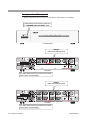
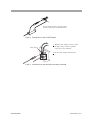
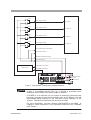
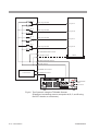
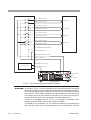
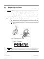
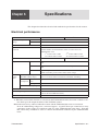
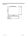
Part No. Z1-002-432, IB002858
Sep. 2009
OPERATION MANUAL
HIGH-VOLTAGE SCANNER
TOS9200 Series
TOS9220
TOS9221
DANGER
This Tester generates high voltage.
Any incorrect handling may cause death.
Read Chapter 2 “PRECAUTIONS ON HANDLING”
in this manual to prevent accident.
Keep this manual together with the manual for
TOS9200/9201, near the tester for easy access
of the operator.
Use of Operation Manual
Please read through and understand this Operation Manual before operating the product. After reading,
always keep the manual nearby so that you may refer to it as needed. When moving the product to another
location, be sure to bring the manual as well.
If you find any incorrectly arranged or missing pages in this manual, they will be replaced. If the manual gets
lost or soiled, a new copy can be provided for a fee. In either case, please contact Kikusui distributor/agent,
and provide the “Kikusui Part No.” given on the cover.
This manual has been prepared with the utmost care; however, if you have any questions, or note any errors or
omissions, please contact Kikusui distributor/agent.
Disposing of used Kikusui products in the EU
Under a law adopted by member nations of the European Union (EU), used electric and electronic products
carrying the symbol below must be disposed of separately from general household waste.
This includes the power cords and other accessories bundled with the products. When disposing of a product subject to these regulations, please follow the guidance of your local
authority, or inquire with your Kikusui distributor/agent where you purchased the product.
The symbol applies only to EU member nations.
Disposal outside the EU
When disposing of an electric or electronic product in a country that is not an EU member, please contact your
local authority and ask for the correct method of disposal.
Reproduction and reprinting of this operation manual, whole or partially, without our permission is prohibited.
Both unit specifications and manual contents are subject to change without notice.
Copyright© 2001-2009 Kikusui Electronics Corporation
To supervisor in charge of operation
• If the operator does not read the language used in this manual, translate the manual into appropriate language.
• Help the operator in understanding this manual before operation.
• Keep this manual together with the manual for TOS9200/9201, near the tester for easy access of the
operator.
For your own safety (to avoid electrification)
While the scanner is delivering its test voltage, never touch the following areas, or else, you will be
electrified, and run the risk of death by electric shock.
• the output terminal
• the test leadwires connected to the output terminal
• the Device Under Test (DUT)
• any par t of the scanner, which is electrically connected to the output terminal, and
• the same par t as above immediately after the output has been cut off when in the DC mode of
test.
Also, electric shock or accident may arise in the following cases:
• the scanner being operated without grounding.
• if the gloves for electrical job are not used.
• approach to any par t connected to the output terminal while the power of the scanner is turned
on.
• the same action as above immediately after the power of tester has been turned off when in the
DC mode of test.
TOS9220/9221
I
Power Requirements of this Product
Power requirements of this product have been changed and the relevant sections of the Operation
Manual should be revised accordingly.
(Revision should be applied to items indicated by a check mark ✓.)
Input voltage
The input voltage of this product is
and the voltage range is
to
VAC,
VAC. Use the product within this range only.
Input fuse
The rating of this product's input fuse is
A,
VAC, and
.
WARNING •
To avoid electrical shock, always disconnect the AC power cord or turn off
the switch on the switchboard before attempting to check or replace the
fuse.
• Use a fuse element having a shape, rating, and characteristics suitable
for this product. The use of a fuse with a different rating or one that short
circuits the fuse holder may result in fire, electric shock, or irreparable
damage.
AC power cord
The product is provided with AC power cords described below. If the cord has no power plug,
attach a power plug or crimp-style terminals to the cord in accordance with the wire colors
specified in the drawing.
WARNING •
The attachment of a power plug or crimp-style terminals must be carried
out by qualified personnel.
Without a plug
Without a plug
Blue (NEUTRAL )
White (NEUTRAL)
Black (LIVE)
Brown (LIVE)
Green/Yellow (GND)
Plug for USA
NEMA5-15
Green or Green/Yellow (GND)
Plug for Europe
CEE7/7
Plug for China
GB1002
Provided by Kikusui distributor/agent
Kikusui agents can provide you with suitable power cord.
For further information, contact Kikusui distributor/agent.
II
TOS9220/9221
Safety Symbols
For the safe use and safe maintenance of this product, the following symbols are used throughout this manual and on the product. Understand
the meanings of the symbols and obser ve the instructions they indicate
(the choice of symbols used depends on the products).
OR
Indicates that a high voltage (over 1 000 V) is used here. Touching the part causes a possibly fatal electric shock. If physical
contact is required by your work, start work only after you make
sure that no voltage is output here.
DANGER
Indicates an imminently hazardous situation which, if ignored,
will result in death or serious injury.
WARNING
Indicates a potentially hazardous situation which, if ignored,
could result in death or serious injur y.
CAUTION
Indicates a potentially hazardous situation which, if ignored, may
result in damage to the product and other proper ty.
Shows that the act indicated is prohibited.
Is placed before the sign “DANGER,” “WARNING,” or “CAUTION” to emphasize these. When this symbol is marked on the
product, see the relevant sections in this manual.
Indicates a protective conductor ter minal.
Indicates a chassis(frame) terminal.
TOS9220/9221
Safety Symbols III
Safety Precautions
The following safety precautions must be observed to avoid fire hazard,
electrical shock, accidents, and other failures. Keep them in mind and
make sure that all of them are observed properly.
Users
• This product must be used only by qualified personnel who understand the contents of this operation manual.
• If it is handled by disqualified personnel, personal injury may result. Be sure to handle it under supervision of qualified personnel (those who have electrical knowledge.)
• This product is not designed or manufactured for general home or consumer use.
tion
Opera
l
Manua
Purposes of use
• Do not use the product for purposes other than those described in the operation
manual.
Line
Voltage
Input power
• Use the product with the specified input power voltage.
• For applying power, use the AC power cord provided. Note that the provided power
cord is not use with some products that can switch among different input power
voltages or use 100 V and 200 V without switching between them. In such a case,
use an appropriate power cord.
Fuse
• With products with a fuse holder on the exterior surface, the fuse can be replaced
with a new one. When replacing a fuse, use the one which has appropriate shape,
ratings, and specifications.
Cover
• There are parts inside the product which may cause physical hazards. Do not
remove the external cover.
IV Safety Precautions
TOS9220/9221
Installation
• When installing products be sure to observe "Precautions for Installation"
described in this manual.
• To avoid electrical shock, connect the protective ground terminal to electrical
ground (safety ground).
• When installing products with casters, be sure to lock the casters.
Relocation
• Turn off the power switch and then disconnect all cables when relocating the
product.
• Use two or more persons when relocating the product which weights more than
20 kg. The weight of the products can be found on the rear panel of the product
and/or in this operation manual.
• Use extra precautions such as using more people when relocating into or out of
present locations including inclines or steps. Also handle carefully when relocating tall products as they can fall over easily.
• Be sure the operation manual be included when the product is relocated.
Operation
k?
hec
C
• Check that the AC input voltage setting and the fuse rating are satisfied and that
there is no abnormality on the surface of the AC power cord. Be sure to unplug
the AC power cord.
• If any abnormality or failure is detected in the products, stop using it immediately.
Unplug the AC power cord. Be careful not to allow the product to be used before
it is completely repaired.
• Do not disassemble or modify the product. If it must be modified, contact Kikusui
distributor/agent.
Maintenance and checking
• To avoid electrical shock, be absolutely sure to unplug the AC power cord before
performing maintenance or checking.
• Do not remove the cover when performing maintenance or checking.
• To maintain performance and safe operation of the product, it is recommended
that periodic maintenance, checking, cleaning, and calibration be performed.
Service
• Internal service is to be done by Kikusui service engineers. If the product must be
adjusted or repaired, contact Kikusui distributor/agent.
TOS9220/9221
Safety Precautions V
Front panel and Rear panel
• Before using the tester, be sure to read Chapter2 "Precautions on Handling".
Lighted lamp means that the scanner is
in “DANGER HIGH VOLTAGE” state.
TOS9220/9221
Danger
HIGH VOLTAGE terminals
TOS9220
To ensure safety, be sure to connect to an earth
ground. See “1.5 Grounding”.
Danger
HIGH VOLTAGE terminals
TOS9221
To ensure safety, be sure to connect to an earth
ground. See “1.5 Grounding”.
VI Safety Precautions
TOS9220/9221
Description of Contents
This manual is composed of the following chapters:
Preface
This section provides an outline of the scanner and explains its features
Chapter 1
Setup
This chapter describes the procedures from unpacking to installation to operation
checking.
Chapter 2
Precautions on Handling
This chapter describes the precautions to be followed in the handling of this scanner. When using the scanner, take utmost care to ensure safety.
Chapter 3
Connections
This chapter describes the connections between the scanner, TOS9200/9201 tester,
and DUT.
Chapter 4
Part Names and Functions
This chapter describes the names and functions of components such as switches,
displays, and connectors on the front and rear panels.
Chapter 5
Maintenance
This chapter describes the maintenance, inspection, and calibration of the scanner.
Chapter 6
Specifications
This chapter describes the electrical and mechanical specifications for the scanner.
TOS9220/9221
Overvoltage category VII
Contents
Safety Symbols - - - - - - - - - - - - - - - - - - - - - - - - - - - - - - - - - - - - - - - - - - - - - - - - III
Safety Precautions - - - - - - - - - - - - - - - - - - - - - - - - - - - - - - - - - - - - - - - - - - - - - - IV
Description of Contents - - - - - - - - - - - - - - - - - - - - - - - - - - - - - - - - - - - - - - - - - VII
Preface
About This Manual - - - - - - - - - - - - - - - - - - - - - - - - - - - - - - - - - - - - - - - - - - - P-1
Outline and Features - - - - - - - - - - - - - - - - - - - - - - - - - - - - - - - - - - - - - - - - - - - P-1
Chapter 1 Setup
1.1
Unpacking - - - - - - - - - - - - - - - - - - - - - - - - - - - - - - - - - - - - - - - - - - - - - - - - - - 1-1
1.2
Precautions for Installation - - - - - - - - - - - - - - - - - - - - - - - - - - - - - - - - - - - - - - - 1-3
1.3
Precautions for Moving - - - - - - - - - - - - - - - - - - - - - - - - - - - - - - - - - - - - - - - - - 1-5
1.4
Connecting the AC Power Cord - - - - - - - - - - - - - - - - - - - - - - - - - - - - - - - - - - - 1-6
1.5
Grounding - - - - - - - - - - - - - - - - - - - - - - - - - - - - - - - - - - - - - - - - - - - - - - - - - - 1-7
Chapter 2 Precautions on Handling
2.1
Do not short the output to the earth ground - - - - - - - - - - - - - - - - - - - - - - - - - - - - 2-1
2.2
Action When in Emergency - - - - - - - - - - - - - - - - - - - - - - - - - - - - - - - - - - - - - - 2-2
2.3
Precautions on Testing- - - - - - - - - - - - - - - - - - - - - - - - - - - - - - - - - - - - - - - - - - 2-2
2.4
Daily Checking - - - - - - - - - - - - - - - - - - - - - - - - - - - - - - - - - - - - - - - - - - - - - - 2-4
Chapter 3 Connections
3.1
Connecting the Scanner to the TOS9200/9201 Tester - - - - - - - - - - - - - - - - - - - - - 3-1
3.2
Connecting the TOS9220 Scanner to the DUT- - - - - - - - - - - - - - - - - - - - - - - - - - 3-6
3.3
Connecting the TOS9221 Scanner to the DUT- - - - - - - - - - - - - - - - - - - - - - - - - 3-11
Chapter 4 Part Names and Functions
4.1
Front Panel - - - - - - - - - - - - - - - - - - - - - - - - - - - - - - - - - - - - - - - - - - - - - - - - - 4-1
4.2
Rear Panel - - - - - - - - - - - - - - - - - - - - - - - - - - - - - - - - - - - - - - - - - - - - - - - - - - 4-2
Chapter 5 Maintenance
VIII Contents
5.1
Cleaning - - - - - - - - - - - - - - - - - - - - - - - - - - - - - - - - - - - - - - - - - - - - - - - - - - - 5-1
5.2
Inspection - - - - - - - - - - - - - - - - - - - - - - - - - - - - - - - - - - - - - - - - - - - - - - - - - - 5-1
5.3
Replacing the Fuse - - - - - - - - - - - - - - - - - - - - - - - - - - - - - - - - - - - - - - - - - - - - 5-2
5.4
Maintenance - - - - - - - - - - - - - - - - - - - - - - - - - - - - - - - - - - - - - - - - - - - - - - - - 5-3
5.5
Troubleshooting - - - - - - - - - - - - - - - - - - - - - - - - - - - - - - - - - - - - - - - - - - - - - - 5-3
TOS9200/9221
Chapter 6 Specifications
Electrical performance - - - - - - - - - - - - - - - - - - - - - - - - - - - - - - - - - - - - - - - - - - 6-1
General Specifications - - - - - - - - - - - - - - - - - - - - - - - - - - - - - - - - - - - - - - - - - - 6-3
Dimensions - - - - - - - - - - - - - - - - - - - - - - - - - - - - - - - - - - - - - - - - - - - - - - - - - 6-4
Index- - - - - - - - - - - - - - - - - - - - - - - - - - - - - - - - - - - - - - - - - - - - - - - - - - - - - - - I-1
TOS9200/9221
Contents IX
X Contents
TOS9200/9221
Preface
About This Manual
This Operation Manual is for the TOS9220 and TOS9221 high-voltage scanners.
In this manual, the TOS9220 or TOS9221 high-voltage scanner is referred to as the
“TOS9220/9221 scanner” or simply the “scanner,” while the TOS9200 or TOS9201
withstanding voltage/insulation resistance tester is referred to as the “TOS9200/
9201 tester” or the “tester proper.” Moreover, the combination of the TOS9200/9201
tester and TOS9220/9221 scanner is referred to as a “test system.”
The manual provides precautions on the handling of the scanner and connections to
the TOS9200/9201 tester and the device under test (DUT). For information on
operations such as setting the scanner output, see the Operation Manual for the
TOS9200/9201 Tester.
Outline and Features
A dedicated option for the TOS9200 and TOS9201 withstanding voltage/insulation
resistance testers, this scanner distributes the test voltage supplied from the tester
proper to multiple test points. It adds the following functions to the TOS9200/9201
tester:
•
•
•
One scanner extends the output to four channels. A potential of HIGH, LOW, or
OPEN can be set for each channel, and an AC/DC withstanding voltage or insulation resistance test can be conducted at any of four test points.
A maximum of four scanners can be connected to one TOS9200/9201 tester.
This allows the output to be extended to up to 16 channels.
The contact between the output of each channel and the corresponding test point
can be checked. (The contact checking function is provided for the TOS9221
scanner only.)
This allows labor-saving, reliable withstanding voltage or insulation resistance testing of electric or electronic equipment or electronic components with multiple test
points.
WARNING • This scanner handles high voltages of 5 kV AC/6 kV DC supplied from the
tester proper. Therefore, do not touch the DUT or cables, as electric shock
may result.
Around the DUT, provide full safety measures such as an enclosure to
keep workers away. In addition, to ensure safety, exercise extreme care to
prevent the output of a high voltage due to improper connections and operations.
TOS9220/9221
Preface P-1
P-2 Preface
TOS9220/9221
Setup
Chapter 1
This chapter describes the procedures from unpacking to installation to operation
checking.
1.1
Unpacking
Upon receiving the product, confirm that the necessary accessories are included and
have not been damaged in transit. Should any damage or shortage be found, please
contact Kikusui distributor/agent.
Fig.1-1 Packing/Unpacking
NOTE
TOS9220/9221
• Retain the packing material for future transport.
Setup 1-1
or
or
Rated voltage: 125 Vac
PLUG: NEMA5-15
[85-AA-0003]
AC power cord (1 pc.)
Rated voltage: 250 Vac
PLUG: CEE7/7
[85-AA-0005]
Rated voltage: 250 Vac
PLUG: GB1002
[85-10-0790]
The power cord that is provided varies depending on
the destination for the product at the factory-shipment.
Four leadwires for TOS9220
Eight leadwires for TOS9221
TL07-TOS high-voltage test leadwires, red
1.5 m
[84180]
TL06-TOS high-voltage leadwires
for parallel connections (1 set)
0.5 m
[84170]
Interface cable (1 pc.)
0.5 m
[85-50-0210]
"HIGH VOLTAGE, DANGER" sticker (2 sheets)
[A8-210-202]
This is contained
in the fuse holder.
Channel indication sticker
For panel surface (1 sheet)
[A8-900-322]
For test leadwires (1 sheet)
[A8-900-335]
Operation Manual (1 copy)
[Z1-002-432]
Spare fuse (1 pc.)
2.5 A, 250 V
[99-00-0027]
Fig.1-2 List of Accessories
NOTE
1-2 Setup
• Place the "DANGER HIGH VOLTAGE" sticker in a visible location near the
scanner or installation site.
TOS9220/9221
1.2
Precautions for Installation
Be sure to observe the following precautions when installing the scanner.
■ Do not use the scanner in a flammable atmosphere.
To prevent explosion or fire, do not use the scanner near alcohol, thinner, or other
combustible materials, or in an atmosphere containing such vapors.
■ Avoid locations where the scanner is exposed to high
temperatures or direct sunlight.
Do not locate the scanner near a heater or in areas subject to drastic temperature
changes.
Operating temperature range: 5 °C to 35 °C (41 °F to 95 °F)
Storage temperature range: -20 °C to 70 °C (-4 °F to 158 °F)
■ Avoid humid environments.
Do not locate the scanner in a high-humidity environment—near a boiler, humidifier, or water supply.
Operating humidity range: 20 % to 80 % RH
(no dew condensation permitted)
Storage humidity range:
90 % RH or less
(no dew condensation permitted)
Condensation may occur even within the operating humidity range. In that case, do
not start using the scanner until the location is completely dry.
■ Do not place the scanner in a corrosive atmosphere.
Do not install the scanner in a corrosive atmosphere or one containing sulfuric acid
mist or the like. This may cause corrosion of various conductors and imperfect contact with connectors, leading to malfunction and failure, or in the worst case, a fire.
■ Do not locate the scanner in a dusty environment.
Dirt and dust in the scanner may cause electrical shock or fi re.
■ Do not use the scanner where ventilation is poor.
Prepare sufficient space around the scanner to allow for air flow.
■ Do not place the scanner on a tilted surface or in a location
subject to vibrations.
If placed on a non-level surface or in a location subject to vibration, the scanner may
fall, resulting in damage and injury.
■ Do not use the scanner in locations affected by strong
magnetic or electric fields.
Operation in a location subject to magnetic or electric fields may cause the scanner
to malfunction, resulting in electrical shock or fire.
TOS9220/9221
Setup 1-3
■ Do not use the scanner in locations near a sensitive
measuring instrument or receiver.
Operation in a location subject, may cause such equipment may be affected by noise generated by the scanner. At a test voltage exceeding 3 kV, corona discharge may be gener-
ated to produce substantial amounts of RF broadband emissions between grips on
the test leadwire. To minimize this effect, secure a sufficient distance between alligator clips.
In addition, keep the alligator clips and test leadwire away from the surfaces of conductors (particularly sharp metal ends).
■ Installation of two or more scanners
The scanner may be placed on the TOS9200/9201 tester. However, to ensure
safety, only one scanner should be stacked on the tester.
When two or more scanners are used, mount them on a rack or install (an)
additional scanner(s) next to the tester proper. Moreover, no more than two
scanners should be stacked on top of each other.
The stacking of two or more scanners
on the tester is prohibited.
Fig.1-3 Installation of Two Scanners
NOTE
1-4 Setup
• The cable supplied with the product is not long enough to connect the scanner
located next to the tester proper. An optional longer cable is available from
Kikusui. If you need this cable, please contact your Kikusui distributor/agent.
TL04-TOS high-voltage leads for parallel connection,
1.5 m [KA-0612-01]
Interface cable,
2 m [85-50-0140]
TOS9220/9221
■ Secure adequate space around the power plug.
Do not insert the power plug to an outlet where accessibility to the plug is poor.
And, do not place objects near the outlet that would result in poor accessibility to
the plug.
1.3
Precautions for Moving
When moving the scanner to the installation site or otherwise transporting it, take
the following precautions:
■ When moving the scanner, Disconnect all wires from it.
Moving the scanner without disconnecting the cables may result in breakage of the
wire or injury due to the scanner tipping over.
■ For transportation, use the special packing material for the
scanner.
Transport the scanner in its original package to prevent vibration and falls, which
may damage the scanner. If you require packing material, contact Kikusui distributor/agent.
TOS9220/9221
Setup 1-5
1.4
Connecting the AC Power Cord
The power cord that is provided varies depending on the destination for the product
at the factory-shipment.
WARNING • This instrument is designed to operate from the over voltage categor y II.
Do not operate it from the over voltage categor y III or IV.
• The AC power cord for 100 V system shown in Fig. 1-4 has a rated voltage
of 125 VAC. If this AC power cord is used at the line voltage of a 200 V system, replace the AC power cord with that satisfying that line voltage.
An appropriate AC power cord must be selected by qualified personnel. If
it is difficult to obtain the AC power cord, consult your Kikusui distributor/
agent
•
Do not use the AC power cord provided with the product as a AC power
cord for other instruments.
Power cord for 100 V system
Rated voltage: 125 VAC
Rated current: 10 A
[85-AA-0003]
PLUG:NEMA5-15
[85-AA-0005]
PLUG:CEE7/7
Power cord for 200 V system
Rated voltage: 250 VAC
Rated current: 10 A
[85-10-0790]
PLUG:GB1002
Fig.1-4 AC power cord
Connect the power cord according to the following procedure:
1.
1-6 Setup
Confirm that the supply voltage is within the line voltage range of the
scanner.
The AC power that can be input is as follows:
Nominal voltage range
Allowable voltage range
Frequency range
100 V to 120 V AC
85 V to 132 V AC
47 Hz to 63 Hz
200 V to 240 V AC
170 V to 250 V AC
47 Hz to 63 Hz
2.
Connect the AC power cord to the AC LINE connector on the rear
panel.
Use the provided power code or power code that is selected by qualified personnel.
3.
Plug in the AC power cord.
TOS9220/9221
1.5
Grounding
WARNING • Be sure to connect the scanner to an electrical ground (safety ground).
If the output to a conveyor or peripheral device that is connected to an
earth ground or a nearby commercial power line is short-circuited without
grounding, the scanner chassis is charged to an excessively high voltage,
resulting in extreme danger.
• This scanner is designed as a Class I equipment (equipment protected
against electric shock with protective grounding in addition to basic insulation). Therefore, electric shock may occur without proper grounding.
To ensure safety, be sure to ground the scanner.
Choose either of the following two available methods of doing so:
1. Connect the AC power cord to a threecontact grounded electrical outlet.
Grounded three-contact
electrical outlet
2. Connect the protective conductor terminal on the rear
panel to the earth ground.
Have specialized engineers select, manufacture, and
install cables.
To ensure secure connection, use proper tools.
Electrical ground
(safety ground)
TOS9220/9221
Setup 1-7
1-8 Setup
TOS9220/9221
Chapter 2
Precautions on Handling
This chapter describes the precautions to be followed in the handling of this scanner.
When using the scanner, take utmost care to ensure safety.
WARNING • The scanner derivers a 5 kVAC/6 kVDC test voltage from the tester proper.
The voltage can cause human injury or death. When operating the scanner, be extremely careful and observe the cautions, warnings, and other
instructions given in this chapter.
2.1
Do not short the output to the earth ground
Pay attention so that the high test voltage line is not shorted to a nearby AC line (*1)
or nearby devices (such as conveyors) which are connected to an earth ground. If it
is shorted, the scanner chassis can be charged up to the hazardous high voltage.
Be sure to connect the protective conductor terminal of the scanner and tester to an
earth line. If this has been securely done, even when the low-voltage terminal (*2)
of the scanner is shorted to a high-voltage terminal (*3), the scanner will not be
damaged and its chassis will not be charged up to the high voltage.
Be sure to use a dedicated tool when grounding the protective grounding terminal.
See "1.5 Grounding".
NOTE
TOS9220/9221
*1The term "AC line" here means the line on which the scanner is operating. That is
the line to whose outlet the AC power cable of the scanner is connected. It may
be of a commercial AC power line or of a private-generator AC power line.
*2Channel configured for the LOW terminal or low-voltage side (LOW)
*3Channel configured for the HIGH VOLTAGE terminal or high-voltage side
(HIGH)
Precautions on Handling 2-1
2.2
Action When in Emergency
In case of an emergency (such as electric shock hazard or burning of DUT), take the
following actions. You may do either (a) or (b) first. But be sure to do both.
(a)Turn OFF the power switch of the tester proper.
(b)Disconnect the AC power cord of the tester proper from the AC line
receptacle.
Finally, disconnect the AC power cord of the scanner from the AC line receptacle.
2.3
Precautions on Testing
■ Wearing Insulation Gloves
When handling the scanner, be sure to wear insulation gloves in order to protect
yourself against high voltages. If no insulation gloves are available on your market,
please order Kikusui distributor/agent for them.
■ Precautions for Pausing Tests
When changing test conditions, press the STOP switch of the tester proper once to
take precautions. If you are not going to resume the test soon or if you are leaving
the Test area, be sure to turn-OFF the POWER switch of the tester proper.
STOP switch
POWER switch
Fig.2-1 Tester Proper (TOS9200)
■ Items Charged Up to Dangerous High Voltages
When in test, the DUT, test leadwires, probes, and output terminals and their vicinities can be charged up to dangerous high voltages. Never touch them when in test.
2-2 Precautions on Handling
TOS9220/9221
WARNING • The vinyl sheaths of the alligator clips of the test leadwires which are sup-
plied accompanying the scanner have no sufficient insulation for the high
test voltages. Never touch them when in test.
Alligator clip
Never touch this part.
Fig.2-2 Supplied test leadwire
■ Matters to be Sure of After Turning-OFF Power
If you have to touch the DUT, test leadwires, probes, and/or output terminals and
their vicinities for re-connections or other reasons, be sure of the following two matters.
(a) The analog voltmeter on the tester proper indicates “zero.”
(b) The DANGER lamp on the tester proper has gone out.
■ Check upon completion of a DC withstanding voltage test/
insulation resistance test
Output of the test voltage in a DC withstanding voltage test or insulation resistance
test causes the capacitors within the tester proper, test leadwires, and DUT to be
charged to high voltages.
The TOS9200/9201 tester features a discharge function. However, never attempt to
touch the DUT, test leadwires, or a high-voltage live part such as the periphery of
the output terminals until the DANGER lamps on the scanner and the tester probes
goes off, due to the possibility of electric shock. For the discharge function, see the
Operation Manual for the TOS9200/9201 Testers.
TOS9220/9221
Precautions on Handling 2-3
2.4
Daily Checking
To avoid accidents, confirm at least the following before starting operation.
Common items for both the TOS9220 and TOS9221 scanners
• The scanner and tester is connected to an ear th ground.
• The coating of the high-voltage test leadwire is free from cracks, fissures, and breakage.
• The high-voltage test leadwire is not broken.
For the TOS9220 scanner
• When a test is star ted at a test voltage of 0 V with the contact check
function set to ON in the tester proper, a CONTACT FAIL judgment must
not be made.
(This inspection checks continuity up to the output relays within the scanner. For more information, see "Contact check function" in "3.2 Connecting the TOS9220 Scanner to the DUT".)
• When the output voltage is increased gradually with the ends of the test
leadwires across the channel used for a test short-circuited, an UPPER
FAIL judgment must be made.
For the TOS9221 scanner
• Short-circuit the ends of the low-voltage test leadwire (output terminal B)
and high-voltage test leadwire (output terminal A) at each channel.
Then, when a test is started at a test voltage of 0 V with the contact
check function of the tester proper set to ON, a CONTACT FAIL judgment must not be made.
• Open the ends of the low-voltage test leadwire (output terminal B) and
high-voltage test leadwire (output terminal A) at each channel. Then,
when a test is started at a test voltage of 0 V with the contact check function of the tester proper set to ON, a CONTACT FAIL judgment must be
made.
• When the output voltage is increased gradually with the ends of the test
leadwires across the channel used for a test short-circuited, an UPPER
FAIL judgment must be made.
2-4 Precautions on Handling
TOS9220/9221
Connections
Chapter 3
This chapter describes the connections between the scanner, TOS9200/9201 tester,
and DUT.
For information on operations such as setting the scanner output after all connections have been made, see the Operation Manual for the TOS9200/9201 Testers.
NOTE
3.1
• This scanner is a dedicated option for the TOS9200 and TOS9201 withstanding
voltage/insulation resistance testers. It cannot be connected to other testers.
Connecting the Scanner to the TOS9200/
9201 Tester
Prior to connection
The following describes important points that must be understood before the
TOS9220/9221 scanner is connected to the TOS9200/9201 tester.
■ Power switch
The scanner has no power switch. Connecting the interface cable between the scanner and the TOS9200/9201 tester causes scanner power to be turned on in conjunction with the POWER switch of the tester proper.
■ Number of scanners to be connected
Up to four TOS9220/9221 scanners can be connected to a TOS9200/9201 tester.
Connection using both the TOS9220 and TOS9221 scanners is also possible.
WARNING • The scanner may be placed on the TOS9200/9201 tester, but no more
than one scanner should be stacked on the tester to ensure safety.
When two or more scanners are used, mount them on a rack or install any
additional scanners next to the tester proper. Moreover, no more than two
scanners should be stacked on top of each other.
NOTE
TOS9220/9221
• The cable supplied with the product is not long enough to connect the scanner
located next to the tester proper. An optional longer cable is available from
Kikusui. If you need this cable, please contact your Kikusui agent.
TL04-TOS high-voltage leads for parallel connection 1.5 m [83000]
Interface cable
2 m [85-50-0140]
Connections 3-1
■ Channel Assignment
The TOS9200/9201 tester assigns channel numbers to the TOS9220/9221 scanners,
treating the scanner directly connected to the tester proper via the interface cable as
the first one, followed by that next closest to the tester proper, and so on. See Fig. 31.
Table 3-1 specifies the correspondence between channels viewed from the tester
proper and the channels of each scanner when the scanners are connected to the
TOS9200/9201 tester.
Table3-1
Correspondence between Channels Viewed from the
Tester Proper and Channels of Each Scanner
Channels of each scanner
1st scanner
2nd scanner
3rd scanner
4th scanner
CH1
CH2
CH3
CH4
CH1
CH2
CH3
CH4
CH1
CH2
CH3
CH4
CH1
CH2
CH3
CH4
Channels viewed from
the tester proper
CH1
CH2
CH3
CH4
CH5
CH6
CH7
CH8
CH9
CH10
CH11
CH12
CH13
CH14
CH15
CH16
NOTE
• When connecting two or more scanners in parallel to the tester proper, attach the
supplied channel-indication stickers to the scanner panels in order to identify the
channels clearly.
3-2 Connections
TOS9220/9221
Procedure for connecting the scanners to the TOS9200/9201 tester
The following provides an example involving the connection of three TOS9220/
9221 scanners to the TOS9200/9201 tester. See Fig. 3-1 and Table 3-2.
NOTE
• When connecting four TOS9220/9221 scanners, connect the 4th scanner to the 3rd
scanner in the same way as the 1st and 2nd scanners and the 2nd and 3rd scanners in
Fig. 3-1.
1.
Turn OFF the POWER switch of the tester proper.
2.
Confirm that the analog voltmeter on the tester proper reads “0.”
3.
Before making connections, check that the cables in use do not contain
a broken wire and that the coating is not damaged.
4.
Connect cables 1 to 3 (interface cables).
The scanner’s SCANNER IN and SCANNER OUT terminals use the same
connectors. Be careful not to confuse them.
5.
Connect cables 4 to 6 (high-voltage leads for parallel connection).
The high-voltage leads are directional. The end with a smaller connector
should be connected to IN, while the other end with a larger connector should
be connected to OUT (or the LOW terminal of the tester proper). Securely fasten the cables using fixing metals to ensure that they are not disconnected accidentally. See Fig. 3-2.
When connecting the high-voltage leads for parallel connection, be sure to
connect them first to the LOW side for the number of scanners, then to the
HIGH VOLTAGE side.
6.
Connect cables 7 to 9 (high-voltage leads for parallel connection).
Each IN HIGH VOLTAGE terminal has a cable clamper to prevent accidental
disconnection. For connection to this terminal, see Fig. 3-3.
7.
Confirm that each cable is connected properly and securely.
In addition, confirm that the GND wire of the AC power cord or the protective
conductor terminal is securely grounded.
WARNING • Improper connection of a cable may cause the scanner chassis and the
entire DUT to be charged to high voltages, thereby posing a danger.
NOTE
TOS9220/9221
• Connecting/disconnecting an interface cable with the POWER switch of the
TOS9200/9201 tester turned ON activates the protection function of the tester
proper, causing “SCANNER” to flash on the LCD. This brings the tester proper
into PROTECTION status. To cancel this status, press the STOP switch.
Connections 3-3
Cable 8
1st
TOS9220/9221
Cable 5
3rd
TOS9220/9221
Cable 1
Cable 9
Cable 7
Cable 3
Cable 4
Cable 6
2nd
TOS9220/9221
TOS9200/9201
Cable 2
Fig.3-1 Connection of Three Scanners to the Tester Proper
Table3-2
Cable
No.
Types of supplied cables
Interface cable
Cable 2
Interface cable
–
Cable 3
Interface cable
–
Cable 4
High-voltage lead for OUTPUT
parallel connection LOW terminal
Cable 5
High-voltage lead for
parallel connection
–
Cable 6
High-voltage lead for
parallel connection
–
Cable 8
Cable 9
1st
TOS9220/9221
scanner
TOS9200/
9201 tester
Cable 1
Cable 7
Cables to be Used in the Connections in Fig. 3-1
SCAN terminal
→
SCANNER
IN terminal
SCANNER
OUT terminal
→
IN
LOW terminal
OUTPUT
LOW terminal
–
3-4 Connections
–
–
3rd
TOS9220/9221
scanner
–
–
SCANNER
IN terminal
SCANNER
OUT terminal
–
OUTPUT
IN
High-voltage lead for
HIGH VOLTAGE → HIGH VOLTAGE
parallel connection
terminal
terminal
OUTPUT
High-voltage lead for
–
HIGH VOLTAGE
parallel connection
terminal
High-voltage lead for
parallel connection
→
2nd
TOS9220/9221
scanner
–
→
–
→
–
IN
LOW terminal
OUTPUT
LOW terminal
–
IN
→ HIGH VOLTAGE
terminal
OUTPUT
HIGH VOLTAGE
terminal
SCANNER
IN terminal
–
→
IN
LOW terminal
–
–
IN
→ HIGH VOLTAGE
terminal
TOS9220/9221
Use the fixing metal to securely fasten
leads in order to prevent disconnection.
Fig.3-2 Connection to the LOW Terminal
1. With the cable clamper raised, connect
the high-voltage leads for parallel
connection to the terminals.
Cable clamper
2. Put the cable clamper back in place.
Locked
Fig.3-3 Connection to the IN HIGH VOLTAGE Terminal
TOS9220/9221
Connections 3-5
3.2
Connecting the TOS9220 Scanner to the DUT
Prior to connection
The following describes important points that must be understood, such as the operation of the TOS9220 scanner, before connecting it to the DUT.
■ Operation of the TOS9220 Scanner
The state in which all four-channel outputs of the TOS9220 scanner are connected
to the test points of the DUT is shown in Fig. 3-4.
In this figure, the TOS9200/9201 tester can set each channel to a potential of HIGH,
LOW, or OPEN, and conduct an AC/DC withstanding voltage test or insulation
resistance test on any of four test points A to D.
For example, when a test is conducted with CH1 (test point A) set to the high-voltage side (HIGH), CH2 (test point B) set to OPEN, and CH3 (test point C) and CH4
(test point D) set to the low-voltage side (LOW), the relays RL 1a, RL 3b, and RL
4b inside the TOS9220 scanner will be turned on.
■ Contact check function
The TOS9220 scanner does not have a contact check function for checking the contacts between the DUT and test leadwires. However, the TOS9200/9201 tester can
activate the contact check function for the TOS9220 scanner. In this case, before
conducting a test the TOS9200/9201 tester turns on both output relays “a” and “b”
of a channel of the scanner through which the test voltage is output, to check the
continuity up to those relays. See Fig. 3-4. As an example, assume that test point A
is set to the high-voltage side (CH1:HIGH) and test point C is set to the low-voltage
side (CH3:LOW). For the procedure for configuring channels, see the Operation
Manual for the TOS9200/9201 Testers.
Pressing the START switch in this condition causes the READY display on the LCD
to go off and turns on relays RL 1a and RL 1b. This enables the TOS9200/9201
tester to conduct a contact check on CH1. Relays RL 3a and RL 3b are then turned
on, enabling a contact check on CH3. The tester proper performs contact checks in
channel order in this way, to check the continuity of all channels set to HIGH or
LOW. If a relay within the scanner fails or a broken wire exists, the TOS9200/9201
tester determines that contact failure has occurred and displays “→← FAIL” at the
upper right of the LCD. The LED of the channel that has failed will light up in
orange.
3-6 Connections
TOS9220/9221
RL 1a
CH1 output terminal
Test point A
RL 1b
RL 2a
CH2 output terminal
Test point B
RL 2b
RL 3a
CH3 output terminal
Test point C
RL 3b
RL 4a
CH4 output terminal
Test point D
RL 4b
OUT HIGH VOLTAGE terminal
OUT LOW terminal
DUT
IN HIGH VOLTAGE terminal
IN LOW terminal
SCANNER OUT terminal
Control circuit
TOS9220
SCANNER IN terminal
SCAN terminal
HIGH VOLTAGE
terminal
LOW terminal
TOS9200/9201
Fig.3-4 Test System 1 Using the TOS9220 Scanner
WARNING • If there is a possibility that the DUT, jig, or the like is grounded, never
attempt to set the GND of the tester proper to GUARD.
If GUARD is to be selected, do not connect a measur ing instrument that
has been grounded at one signal ter minal, such as the Kikusui 149-10A
high-voltage digital voltmeter or the TOS1200 current calibrator, to the
scanner. Otherwise, the ammeter will be shor t-circuited.
For more information, see item “Setting LOW/GUARD for the GND ” in
Chapter 3 “Basic Operations” of the Operation Manual for the TOS9200/
9201 Testers.
TOS9220/9221
Connections 3-7
RL 1a
CH1 output terminal
Test point A
RL 1b
RL 2a
CH2 output terminal
Test point B
RL 2b
RL 3a
CH3 output terminal
Test point C
RL 3b
RL 4a
CH4 output terminal
Test point D
RL 4b
OUT HIGH VOLTAGE terminal
DUT
OUT LOW terminal
Chassis
IN HIGH VOLTAGE terminal
IN LOW terminal
SCANNER OUT terminal
Control circuit
TOS9220
SCANNER IN terminal
SCAN terminal
HIGH VOLTAGE
terminal
LOW terminal
TOS9200/9201
Fig.3-5 Test System 2 Using the TOS9220 Scanner
(Example of conducting a test on test points A, B, C, and D using
the DUT chassis as a reference)
3-8 Connections
TOS9220/9221
■ Reducing the effects of noise
If a short circuit or breakdown occur, noise generated can lead to the malfunctioning
of peripheral electronic components. To reduce the effects of noise, install a toroidal
core or a resistor of approximately 470 Ω between the DUT and the end of the highvoltage test leadwire from the scanner, and between the DUT and the end of the
low-voltage test leadwire, as close as possible to the DUT. See Fig. 3-6.
Using a toroidal core, it is recommended that a divisible core be used for power
cable with a diameter of approximately 20 mm, and that it be wound two or three
times around the core.
When connecting a resistor, check its power rating. For an upper current of 10 mA
or less, use a resistor of approximately 470 Ω (3 W, impulse withstanding voltage of
30 kV). When such a resistor is connected, the voltage actually applied to the DUT
is slightly smaller than the output-terminal voltage (approximately 10 V less at 10
mA) due to a voltage drop caused by the resistor. This type of resistor is highly useful in reducing the effects of noise.
Toroidal core
Output terminals
DUT
Toroidal core
TOS9220
Location as close as
possible to the DUT
470 Ω, 3 W
Output terminals
DUT
470 Ω, 3 W
TOS9220
Location as close as
possible to the DUT
Fig.3-6 Reducing the Effects of Noise Generated by the Scanner
TOS9220/9221
Connections 3-9
Procedure for connecting the scanner to the DUT
1.
Turn OFF the POWER switch of the tester proper.
2.
Confirm that the analog voltmeter on the tester proper reads “0.”
3.
Before making connections, check that the test leadwires in use do not
contain broken wires and that the coating is not damaged.
4.
Connect the test leadwires to the output ter minals of the channels to be
used for a test.
The connection to the output terminals is the same as that to the IN HIGH
VOLTAGE terminal. See Fig. 3-3.
5.
Connect the test leadwires to the DUT.
6.
Confirm that the test leadwires are connected proper ly and securely.
Confirm that the cable clamper is securely fastened.
When two or more scanners have been connected in parallel, pay attention to
the relationship between the channels viewed from the tester proper and those
of each scanner. Confirm that the channels set on the tester proper agree with
those of the test points to which the test leadwires have been connected.
WARNING • To ensure safety, do not connect the test leadwires to the output terminals
of a channel not used for a test. If test leadwires are connected to such a
channel, set that channel to LOW. For more information, see the following
notes.
NOTE
3-10 Connections
• The test voltage applied to the channels set to HIGH leaks into the output terminals of a channel that has been set to OPEN on the tester proper, through stray
capacitances within the scanner. Moreover, if test leadwires have been connected
to a channel set to OPEN, the voltage also leaks to its output terminals through
stray capacitance between the test leadwires.
To prevent the unintentional application of voltage to a test point by this leakage
voltage, do not connect test leadwires to the output terminals of a channel set to
OPEN. However, for tests that are conducted by switching voltage application
points in turn with test leadwires connected to multiple test points, such unintentional application of voltage can be prevented by setting channels irrelevant to the
test to LOW.
• To clearly indicate the correspondence between the connected test leadwires and
channels, attach the supplied channel-indication seals to the test leadwires.
TOS9220/9221
3.3
Connecting the TOS9221 Scanner to the DUT
The following describes important points that must be understood, such as the operation of the TOS9221 scanner, before connecting it to the DUT.
■ Operation of the TOS9221 Scanner
The state of the connections of all four channel outputs of the TOS9221 scanner to
the test points of the DUT is shown in Fig. 3-7.
As can be seen from the figure, the A-terminal side of each channel output is connected to the HIHG VOLTAGE terminals of the scanner, while the B-terminal side
is connected to the LOW terminals.
In Fig. 3-7, the TOS9200/9201 tester can set each channel to a potential of HIGH,
LOW, or OPEN, and can conduct an AC/DC withstanding voltage test or insulation
resistance test on any of four test points A to D.
For example, when a test is conducted with CH1 (test point A) set to the high-voltage side (HIGH), CH2 (test point B) set to OPEN, and CH3 (test point C) and CH4
(test point D) set to the low-voltage side (LOW), the relays RL 1a, RL 3b, and RL
4b within the TOS9221 scanner will be turned on.
■ Contact check function
The contact check function checks whether test leadwires properly contact the out put terminals of each channel to the corresponding test point of the DUT. It is also
capable of detecting a broken wire in a test leadwire, contact failure, or a faulty
relay within the scanner.
Pressing the START switch of the TOS9200/9201 tester with the contact check
function set to ON enables the contact check to be conducted before a test is started.
The tester proper turns on both output relays “a” and “b” of the scanner for every set
channel, applies a voltage of approx. 2 V DC, and measures the current to check
continuity between the test leadwires and the DUT. See Fig. 3-7.
As an example, assume that test point A is set to the high-voltage side (CH1:HIGH)
and test point C is set to the low-voltage side (CH3:LOW). For information on the
procedure for configuring the channels, see the Operation Manual for the TOS9200/
9201 Testers.
Pressing the START switch in this condition causes the “READY” display on the
LCD to go off and turns on relays RL 1a and RL 1b. This enables the TOS9200/
9201 tester to check the continuity between the CH1 output terminals and test point
A. Relays RL 3a and RL 3b are then turned on, enabling the tester proper to check
the continuity between the CH3 output terminals and test point C. Before starting a
test, the tester proper performs the contact check in channel order in this way to
check the continuity of all the channels set to HIGH or LOW. For the channel under
contact check, the LED lights up in orange. For a channel set to OPEN, no contact
check will be conducted.
If a connection failure occurs in the wiring between the scanner and DUT, as shown
in Fig. 3-8, or a test leadwire contains a broken wire, no current flows between the
CHxA and CHxB output terminals. Thus, the TOS9200/9201 tester determines that
contact failure has occurred and displays “→← FAIL” at the upper right of the
LCD. The tester stops the contact check at the failed channel, and the LED for that
channel lights up in orange.
TOS9220/9221
Connections 3-11
RL 1a
CH1 A output terminal
RL 1b
CH1 B output terminal
RL 2a
CH2 A output terminal
RL 2b
CH2 B output terminal
RL 3a
CH3 A output terminal
RL 3b
CH3 B output terminal
RL 4a
CH4 A output terminal
RL 4b
CH4 B output terminal
Test point A
Test point B
Test point C
Test point D
OUT HIGH VOLTAGE terminal
OUT LOW terminal
DUT
IN HIGH VOLTAGE terminal
IN LOW terminal
SCANNER OUT terminal
Control circuit
TOS9221
SCANNER IN terminal
SCAN terminal
HIGH VOLTAGE
terminal
LOW terminal
TOS9200/9201
Fig.3-7 Test System Using the TOS9221 Scanner
WARNING • As shown in Fig. 3-7, the test leadwire of a B-output ter minal is connected
to the test leadwire of an A-output ter minal at the corresponding test point.
During a test, high voltage is applied to a point prior to the relay of a B-output terminal. The B-output ter minals are output ter minals connected to the
low-voltage side, but they should be handled in the same way as the Aoutput terminals, which are connected to the high-voltage side.
• If there is a possibility that the DUT, jig, or the like is grounded, never
attempt to set the GND of the tester proper to GUARD.
If GUARD is to be selected, do not connect a measuring instrument that
has been grounded at one signal terminal, such as the Kikusui 149-10A
3-12 Connections
TOS9220/9221
high-voltage digital voltmeter or the TOS1200 current calibrator, to the
scanner. Otherwise, the ammeter will be short-circuited.
For more information, see “Setting LOW/GUARD for the GND” in Chapter
3 “Basic Operations” of the Operation Manual for the TOS9200/9201
Testers.
RL 1a
CH1 A output terminal
RL 1b
CH1 B output terminal
Test point A
Relay on
TOS9221
DUT
Fig.3-8 Connection Failure
Procedure for connecting the scanner to the DUT
1.
Turn OFF the POWER switch of the tester proper.
2.
Confirm that the analog voltmeter on the tester proper reads “0.”
3.
Before making connections, check that the test leadwires in use do not
contain broken wires and that the coating is not damaged.
4.
Connect the test leadwires to the output terminals of channels to be
used for a test.
The connection to the output terminals is the same as that to the IN HIGH
VOLTAGE terminal. See Fig. 3-3.
If the contact check function is not used, it is not necessary to connect the test
leadwires to both the A and B output terminals as shown in Fig. 3-7.
5.
Connect the test leadwires to the DUT.
6.
Confirm that the test leadwires are connected properly and securely.
Confirm that the cable clamper has been securely fastened.
When two or more scanners have been connected in parallel, note the relationship between the channels viewed from the tester proper and those of each
scanner. Confirm that the channels set on the tester proper agree with those of
the test points to which the test leadwires have been connected.
WARNING • To ensure safety, do not connect test leadwires to the output terminals of a
channel not being used for a test. If test leadwires are connected to such
a channel, set that channel to LOW. For more information, see the following notes:
TOS9220/9221
Connections 3-13
NOTE
3-14 Connections
• The test voltage applied to channels set to HIGH leaks into the output terminals of
a channel that has been set to OPEN on the tester proper through stray capacitances within the scanner. Moreover, if test leadwires have been connected to a
channel set to OPEN, the voltage also leaks to its output terminals through stray
capacitance between the test leadwires.
To prevent the unintentional application of voltage to a test point by this leakage
voltage, do not connect test leadwires to the output terminals of a channel set to
OPEN. However, for tests conducted by switching voltage application points in
turn with the test leadwires connected to multiple test points, such unintentional
voltage application can be prevented by setting channels not involved in a test to
LOW.
• To clearly indicate the correspondence between the connected test leadwires and
channels, attach the supplied channel indication seals to the test leadwires.
TOS9220/9221
Chapter 4
Part Names and Functions
This chapter describes the names and functions of components such as switches,
displays, and connectors on the front and rear panels.
4.1
Front Panel
[2]
[1]
[3]
Fig.4-1 Front Panel
(The figure shows model TOS9220.)
[1]
DANGER
This red lamp indicates that a high voltage is being output.
Since it is interlocked with the DANGER lamp of the tester proper, it lights up
during tests, as long as an output voltage remains at the output terminals, or during automatic testing.
[2]
CHANNEL
Indicates the status of each channel during a test. The channel status is represented as shown below, depending on the color of the LED lit.
Red: The channel has been set to HIGH.
Green: The channel has been set to LOW.
Orange: A contact check is being conducted. Following the check, it also
lights up if the corresponding channel has failed.
The LEDs of channels through which a test is not conducted will be unlit.
[3]
POWER
When the scanner is connected to the TOS9200/9201 tester, this indicator lights
up (in green), as it is interlocked with the POWER switch of the tester proper.
TOS9220/9221
Part Names and Functions 4-1
4.2
[4]
[13] [14]
Rear Panel
[5]
[9]
[11]
[10]
[12]
[7]
[9]
[11]
[8]
[10]
[12]
[6]
[15]
Fig.4-2 TOS9220 Rear Panel
[4]
[13] [14]
[5]
[15]
Fig.4-3 TOS9221 Rear Panel
[4]
SCANNER IN
This connector connects to the SCAN connector of the TOS9200/9201 tester.
When multiple scanners are connected in parallel, it connects to the SCANNER
OUT connector of another TOS9220/9221 scanner.
[5]
SCANNER OUT
When multiple scanners are connected in parallel, this connector connects to the
SCANNER IN connector of another TOS9220/9221 scanner.
[6]
OUTPUT (TOS9220 only)
This part provides the output terminal of each channel.
Of the four output terminals, the output terminal of a channel configured for the
high-voltage side (HIGH) on the tester proper is connected to the high-voltage
side (HIGH VOLTAGE potential) of the test voltage. In addition, the output terminal of a channel configured for the low-voltage side (LOW) is connected to the
low-voltage side (LOW potential) of the test voltage.
4-2 Part Names and Functions
TOS9220/9221
[7]
OUTPUT A (TOS9221 only)
The A-output terminal of each channel is an output terminal on the high-voltage
side (HIGH VOLTAGE).
The A-output terminal of a channel set to HIGH on the TOS9200/9201 tester is
connected to the high-voltage side (HIGH VOLTAGE potential) of the test voltage. The A-output terminal of a channel not set to HIGH is in the open state (not
connected to another point).
[8]
OUTPUT B (TOS9221 only)
The B-output terminal of each channel is an output terminal on the low-voltage
side (LOW).
The B-output terminal of a channel set to LOW on the TOS9200/9201 tester is
connected to the low-voltage side (LOW potential) of the test voltage. The B-output terminal of a channel not set to LOW is in the open state (not connected to
another point).
When the tester proper has activated the contact check function, voltage is temporarily applied to the B-output terminals of channels set to both the high-voltage
and low-voltage sides, in order to check the contact condition. Since in this wiring configuration high voltage is also applied to the four terminals provided as the
low-voltage side output terminals, they should be handled in the same way as the
A-output terminals.
[9]
IN HIGH VOLTAGE
This terminal connects to the OUT HIGH VOLTAGE terminal of the tester proper
or to another TOS9220/9221 scanner connected in parallel, in order to receive the
test voltage from the TOS9200/9201 tester. During a test, the test voltage is supplied continuously.
[10] IN LOW
This terminal connects to the LOW terminal of the TOS9200/9201 tester or to the
OUT LOW terminal of another TOS9220/9221 scanner connected in parallel.
[11] OUT HIGH VOLTAGE
This terminal supplies the test voltage supplied from the tester proper to the IN
HIGH VOLTAGE terminal of another TOS9220/9221 scanner connected in parallel when multiple scanners are used in parallel connection. During a test, the test
voltage is supplied at all times.
NOTE
• This terminal is not used to connect to the DUT.
[12] OUT LOW
This terminal connects to the IN LOW terminal of another TOS9220/9221 scanner when multiple scanners are used in parallel configurations.
TOS9220/9221
Part Names and Functions 4-3
[13] Protective conductor terminal
This terminal is used to ground the scanner.
WARNING • Always ground the scanner. For more information, see “1.5 Grounding.”
[14] AC LINE
This is the connector for the AC power cord that supplies power to the scanner.
WARNING • Improper handling of the AC LINE connector may result in electric shock.
Be sure to follow the instructions in "1.4 Connecting the AC Power Cord".
• To ensure safety, be sure to ground the scanner. For more information,
see “1.5 Grounding.”
[15] Fuse holder
This contains an AC input fuse and a spare fuse.
WARNING • Improper handling of the fuse may result in electric shock. Before replac-
ing or checking the fuse, see "5.3 Replacing the Fuse".
4-4 Part Names and Functions
TOS9220/9221
Maintenance
Chapter 5
This chapter describes the maintenance, inspection, and calibration of the scanner.
Regular maintenance and inspection are necessary to maintain the initial performance of the product.
5.1
Cleaning
To clean the surface of the tester, including the panel, wipe it with a soft cloth moistened with water-diluted neutral detergent.
WARNING • Before starting cleaning, be sure to turn off the POWER switch of the
tester proper and unplug the scanner’s AC power cord.
CAUTION • Do not use volatile materials such as thinner and benzene. These materi-
als may change surface colors, or erase prints.
5.2
Inspection
WARNING • Tearing and breakage of the cable coating may lead to electric shock and
fire. In such a case, immediately discontinue use of the scanner.
To purchase accessories, contact Kikusui distributor/agent.
■ AC power cord
Check for tears in the cable coating, looseness and fracture of the plug, and break age of the cable.
■ High-voltage test leadwires
Check the cable coating for tears, fissures, and breakage.
TOS9220/9221
Maintenance 5-1
5.3
Replacing the Fuse
WARNING • To prevent electric shock, before checking or replacing the fuse, be sure to
turn off the POWER switch of the tester proper and unplug the scanner’s
AC power cord.
• Make sure that the fuse used conforms to the instrument specifications,
including shape, rating, and characteristics. Using a fuse with different rating or shor t-circuiting, the fuse holder will damage the instr ument.
1.
Turn off the POWER switch of the tester proper and unplug the scanner’s AC power cord from the electrical outlet.
2.
Disconnect the AC power cord from the AC LINE connector on the rear
panel.
3.
Use a slotted-head screw driver to remove the fuse holder, as shown in
Fig. 5-1.
Fuse
Spare fuse
Fig.5-1 Removing the Fuse Holder
Table5-1
Fuse Rating
100-120V
47-63Hz
200-240V
40
NOTE
• The pre-arcing time-current characteristic of fuses are named differently in the UL
and IEC standards. Use fuses conforming to both or either of the standards.
5-2 Maintenance
TOS9220/9221
5.4
Maintenance
WARNING • The TOS9220/9221 scanner handles voltages as high as 5 kV AC/6 kV
DC. Since maintenance of the scanner, such as an overhaul, involves
considerable risk, all maintenance should be performed by our service
personnel.
■ High-voltage relays
The high-voltage relays inside the scanner are consumables. Although service life
depends on the usage environment, we recommend that the high-voltage relays be
replaced every one million withstanding voltage tests. We also recommend regular
internal inspections and cleaning at the same intervals.
5.5
Troubleshooting
Not all problems involve mechanical failures. Before requesting repair service,
recheck your problem. Since a malfunction may also be due to the tester proper, see
"7.5 Troubleshooting" in the Operation Manual for the TOS9200/9201.
Find your problem in the list below, and correct it as instructed. If it still persists or
if you cannot find it in the list, contact Kikusui distributor/agent.
Symptom1: The POWER ON LED does not light up.
Possible cause
The AC power cord is disconnected.
•
The fuse is blown.
•
The interface cable is disconnected.
•
The POWER switch of the TOS9200/9201 tester
is not turned ON.
•
TOS9220/9221
Remedy
Connect the power cord properly by referring to "1.4
Connecting the AC Power Cord".
Replace the fuse with a new one by referring to "5.3
Replacing the Fuse".
Connect the cable properly by referring to "3.1
Connecting the Scanner to the TOS9200/9201
Tester".
Power to the scanner will be turned on in conjunction
with the tester proper’s POWER switch.
Turn ON the POWER switch of the tester proper in
accordance with the instructions given in “3.1 Turning
ON the Power” of the Operation Manual for the
TOS9200/9201 Tester.
Maintenance 5-3
Symptom2: The POWER ON LED is lit, but the scanner does not
function.
Possible cause
The SCAN terminal of the tester proper is
connected to the SCANNER OUT terminal of
the scanner.
A channel not configured on the TOS9200/9201
tester is being used.
•
•
Remedy
The interface cable is not connected correctly. Connect it
correctly by referring to "3.1 Connecting the Scanner
to the TOS9200/9201 Tester".
Channels connected to test points must be set on the
tester proper.
For information on the procedure for setting channels,
see “Channel settings for the high-voltage scanner ” in
Chapter 3 “Basic Operations” of the Operation Manual
for the TOS9200/9201 Tester.
Symptom3: Pressing the START switch with the contact check
function activated results in an immediate FAIL judgment.
Possible cause
A high-voltage lead for parallel connection is
disconnected.
The OUTPUT A and B terminals are not
connected to the corresponding test point, or a
wire is disconnected in any of the connections
(TOS9220 only).
5-4 Maintenance
•
•
Remedy
Connect the high-voltage leads properly by referring to
"3.1 Connecting the Scanner to the TOS9200/9201
Tester".
Install or reconnect the leads properly and securely by
referring to "3.3 Connecting the TOS9221 Scanner to
the DUT".
TOS9220/9221
Specifications
Chapter 6
This chapter describes the electrical and mechanical specifications for the scanner.
Electrical performance
Item
Maximum rating
voltage
TOS9220
AC
5.0 kV
DC
6.0 kV
TOS9221
Number of channels
4 (Each channel is settable to HIGH, LOW, or OPEN.)
Maximum number of scanners
connected
4 scanners
Channel numbers are determined in order of connection to the
TOS9200/9201 tester.
1st scanner CH1 to CH4
3rd scanner CH9 to CH12
Contact check function
Lamps and LEDs
Power
requirements
None*1
2nd scanner CH5 to CH8
4th scanner CH13 to CH16
Provided
POWER
Lights as it is interlocked with the POWER switch of the TOS9200/9201
tester
DANGER
Lights as it is interlocked with the DANGER lamp of the TOS9200/9201
tester
CHANNEL
Lights during a test at each channel
HIGH: red; LOW: green; Under contact check: orange
Nominal voltage range
(allowable voltage range)
100 V to 120 V AC/200 V to 240 V AC
(85 V to 132 V AC/170 V to 250 V AC) Automatic switching
Power
consumption
In READY
state
Approx. 12 VA
During test
40 VA maximum
Allowable frequency range
47 Hz to 63 Hz
Insulation resistance
30 MΩ or more (500 V DC) [between the AC LINE and chassis]
Withstanding voltage
1 390 V AC, 2 seconds, 10 mA or less
[between the AC LINE and chassis]
Earth continuity
25 A AC/0.1 Ω or less
*1 When the contact check function is activated on the TOS9220/9201 tester, the tester conducts a contact check up to the output terminals of the TOS9220 scanner.
Measurement accuracy achieved when the scanner and the TOS9220/9201 tester are connected:
In an AC withstanding voltage test, a current of approx. 22 μA/kV flows per scanner due to stray
capacitance in the scanner in comparison with use of the TOS9220/9201 tester alone. Note that
this current may contribute to errors in current measurements conducted by the TOS9220/9201
tester.
TOS9220/9221
Specifications 6-1
Item
TOS9220
TOS9221
Safety*2, *3
Conforms to the requirements of the following directive and standard.
Low Voltage Directive 2006/95/EC
EN61010-1
Class I
Pollution degree 2
Electromagnetic compatibility
(EMC)*2
Conforms to the requirements of the following directive and standard.
EMC Directive 2004/108/EC
EN61326-1
EN61000-3-2
EN61000-3-3
Under following conditions
1. Used test leadwire TL07-TOS which is supplied.
2. No discharge occurs at outside of the tester.
3. Used the shielded cable which length is less than three meters when
the SIGNAL I/O is used.
*2 Only on models that have CE marking on the panel.
Not applicable to custom order models.
*3 This instrument is a Class I equipment. Be sure to ground the protective conductor terminal of the
instrument. The safety of the instrument is not guaranteed unless the instrument is grounded properly.
6-2 Specifications
TOS9220/9221
General Specifications
Item
Environment
TOS9220
Installation location
Indoors and at altitudes up to 2 000 m
Warranty
range
Temperature
5 ˚C to 35 ˚C (41 °F to 95 °F)
Humidity
20 % to 80 % RH (no condensation)
Operating
range
Temperature
0 ˚C to 40 ˚C (32 °F to 104 °F)
Humidity
20 % to 80 % RH (no condensation)
Storage range Temperature
Humidity
-20 ˚C to 70 ˚C (-4 °F to 158 °F)
90 % RH or less (no condensation)
Dimensions
See Fig. 6-1 Dimensions.
Weight
Approx. 6.5 kg (14.33 lb)
Accessories
TOS9221
AC power cord
1 pc.
High-voltage test leadwires,
red
4 pc. (1.5 m each)
High-voltage leads for
parallel connection
1 set (0.5 m each)
Interface cable
1 pc.(0.5 m)
Channel-indication stickers
For the panel face: 1 sheet; for the test leadwires: 1
“HIGH VOLTAGE,
DANGER” stickers
2 sheets
Fuses
2 pc. (including a spare contained in the fuse holder)
Operation Manual
1 copy
TOS9220/9221
8 pc. (1.5 m each)
Specifications 6-3
370 (14.57)
88 (3.46)
MAX105 (4.13)
MAX5
(0.20)
MAX415 (16.33)
Dimensions
MAX435 (17.13)
430 (16.93)
Unit: mm (inch)
Fig.6-1 Dimensions
6-4 Specifications
TOS9220/9221
Index
A
M
AC LINE 4-4
AC power cord 1-6
accessories 1-2
alligator clips 2-3
maintenance 5-3
Moving 1-5
C
CHANNEL 4-1
channel assignment 3-2
Class I device 1-7
cleaning 5-1
connecting to the DUT
TOS9220 scanner 3-6
TOS9221 scanner 3-11
connecting to the tester 3-1
contact check function
TOS9220 scanner 3-6
TOS9221 scanner 3-11
D
N
number of scanners to be connected 3-1
O
OUT HIGH VOLTAGE 4-3
OUT LOW 4-3
OUTPUT (TOS9220 only) 4-2
OUTPUT A (TOS9221 only) 4-3
OUTPUT B (TOS9221 only) 4-3
overhaul 5-3
P
packing 1-1
POWER 4-1
power switch 3-1
protective conductor terminal 1-7, 4-4
DANGER 4-1
R
F
fuse holder 4-4
reducing the effects of noise 3-9
replacing the Fuse 5-2
G
S
grounding 1-7
SCANNER IN 4-2
scanner operations
TOS9220 scanner 3-6
TOS9221 scanner 3-11
SCANNER OUT 4-2
startup inspection 2-4
H
high-voltage relay 5-3
I
IN HIGH VOLTAGE 4-3
IN LOW 4-3
inspection 5-1
Installation 1-3
TOS9200/9221
T
Troubleshooting 5-3
Index I-1


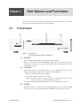


![AC5kV・DC6kV耐電圧・絶縁抵抗試験器[TOS9200シリーズ]](http://vs1.manualzilla.com/store/data/006653480_2-5da8d60b01118d8984306d04f8a5e0b9-150x150.png)