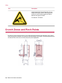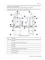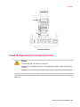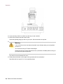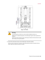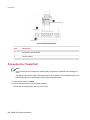
1
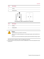
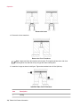
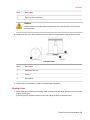
Triaxial Cell Product Information
Models 656.04, 656.05, and 656.06
015-025-501 B
be certain.
©
2014MTS Systems Corporation. All rights reserved.
Original Instructions (English): 015-025-501 B—January 2014
Trademark Information
MTS, be certain., Bionix, ElastomerExpress, FlatTrac, FlexTest, Just In Case, LevelPlus, MTS Criterion,
MTS EM Extend, MTS Insight, MTS Landmark, RPC, ServoSensor, SWIFT, Temposonics, TestWare,
TestWorks are registered trademarks of MTS Systems Corporation within the United States. Acumen,
Advantage, Aero ST, Aero-90, AeroPro, Criterion, CRPC, Echo, Flat-Trac, Landmark, MAST,
MicroProfiler, MPT, MTS Acumen, MTS Echo, MTS Fundamentals, MTS TestSuite, ReNew, SilentFlo,
TempoGuard, TestLine, and Tytron are trademarks of MTS Systems Corporation within the United
States. These trademarks may be registered in other countries. All other trademarks are property of
their respective owners. All other trademarks are property of their respective owners.
Proprietary Software
Software use and license is governed by the MTS End User License Agreement which defines all
rights retained by MTS and granted to the End User. All Software is proprietary, confidential, and
owned by MTS Systems Corporation and cannot be copied, reproduced, disassembled, decompiled,
reverse engineered, or distributed without express written consent of MTS.
Software Verification and Validation
MTS software is developed using established quality practices in accordance with the requirements
detailed in the ISO 9001 standards. Because MTS-authored software is delivered in binary format, it
is not user accessible. This software will not change over time. Many releases are written to be
backwards compatible, creating another form of verification. The status and validity of the MTS operating
software is also checked during system verification and routine calibration of MTS hardware. These
controlled calibration processes compare the final test results after statistical analysis against the
predicted response of the calibration standards. With these established methods, MTS assures its
customers that MTS products meet exacting quality standards when initially installed and will continue
to perform as intended over time.
Manual Part Number—Publication Date—Release
015-025-501 A—June 1992
Table of Contents
Table of Contents
Technical Support
How to Get Technical Support.........................................................................................................................5
Before You Contact MTS.................................................................................................................................5
If You Contact MTS by Phone.........................................................................................................................7
Problem Submittal Form in MTS Manuals......................................................................................................8
Preface
Before You Begin.............................................................................................................................................9
Documentation Conventions............................................................................................................................9
Safety
General Safety Practices.................................................................................................................................14
Safety Practices Before Operating the System...............................................................................................14
Safety Practices While Operating the System ...............................................................................................19
Hazard Labels.................................................................................................................................................21
Crunch Zones and Pinch Points.....................................................................................................................22
Introduction
Introduction....................................................................................................................................................24
Description.....................................................................................................................................................24
Triaxial Cell Specifications............................................................................................................................32
Operation
Operation........................................................................................................................................................36
Moving and Mounting the Bell......................................................................................................................36
Performing Tests.............................................................................................................................................37
Prepare the Specimen for Pore Pressure/Extension Tests..................................................................37
Prepare the Specimen for Compression Tests....................................................................................39
Raise and Lock the Bell......................................................................................................................40
Install the Specimen for Extension/Pore Pressure Tests....................................................................42
Install the Specimen for a Compression Test.....................................................................................47
Pressurize the Triaxial Cell................................................................................................................50
Remove the Old Specimen.................................................................................................................54
Changing Between Extension/Pore Pressure and Compression Test Setups.................................................62
Changing to a Compression Test Setup..............................................................................................63
Raise and Lock the Bell..........................................................................................................64
Change the Force Transducer.................................................................................................66
3
Table of Contents
Install the Spherical Platen.....................................................................................................69
Plug the Ports.........................................................................................................................70
Changing to an Extension-Pore Pressure Test Setup..........................................................................72
Raise and Lock the Bell..........................................................................................................73
Remove the Spherical Platen..................................................................................................75
Change the Force Transducer.................................................................................................76
Unplug Lines..........................................................................................................................79
Maintenance
Maintenance...................................................................................................................................................84
4
Technical Support
How to Get Technical Support
Start with your manuals
The manuals supplied by MTS provide most of the information you need to use and maintain your equipment.
If your equipment includes software, look for online help and README files that contain additional product
information.
Technical support methods
MTS provides a full range of support services after your system is installed. If you have any questions
about a system or product, contact Technical Support in one of the following ways.
Web site
www.mts.com > Contact Us (upper-right corner) > In the Subject field, choose
To escalate a problem; Problem Submittal Form
E-mail
Worldwide: [email protected]
Europe: [email protected]
Telephone
Worldwide: 1 800 328 2255 - toll free in U.S.; +1 952 937 4000 - outside U.S.
Europe: +800 81002 222, International toll free in Europe
Outside the U.S.
For technical support outside the United States, contact your local sales and service office. For a list of
worldwide sales and service locations and contact information, use the Global MTS link at the MTS web
site:
www.mts.com > Global Presence > Choose a Region
Before You Contact MTS
MTS can help you more efficiently if you have the following information available when you contact us for
support.
Know your site number and system number
The site number contains your company number and identifies your equipment type (such as material
testing or simulation). The number is typically written on a label on your equipment before the system
leaves MTS. If you do not know your MTS site number, contact your sales engineer.
Example site number: 571167
Triaxial Cell Product Information | 5
Technical Support
When you have more than one MTS system, the system job number identifies your system. You can find
your job number in your order paperwork.
Example system number: US1.42460
Know information from prior technical assistance
If you have contacted MTS about this problem before, we can recall your file based on the:
•
MTS notification number
•
Name of the person who helped you
Identify the problem
Describe the problem and know the answers to the following questions:
•
How long and how often has the problem occurred?
•
Can you reproduce the problem?
•
Were any hardware or software changes made to the system before the problem started?
•
What are the equipment model numbers?
•
What is the controller model (if applicable)?
•
What is the system configuration?
Know relevant computer information
For a computer problem, have the following information available:
•
Manufacturer’s name and model number
•
Operating software type and service patch information
•
Amount of system memory
•
Amount of free space on the hard drive where the application resides
•
Current status of hard-drive fragmentation
•
Connection status to a corporate network
Know relevant software information
For software application problems, have the following information available:
•
The software application’s name, version number, build number, and (if available) software patch
number. This information can typically be found in the About selection in the Help menu.
•
The names of other applications on your computer, such as:
— Anti-virus software
— Screen savers
— Keyboard enhancers
— Print spoolers
6 | Triaxial Cell Product Information
Technical Support
— Messaging applications
If You Contact MTS by Phone
A Call Center agent registers your call before connecting you with a technical support specialist. The agent
asks you for your:
•
Site number
•
Name
•
Company name
•
Company address
•
Phone number where you can be reached
If your issue has a notification number, please provide that number. A new issue will be assigned a unique
notification number.
Identify system type
To enable the Call Center agent to connect you with the most qualified technical support specialist available,
identify your system as one of the following types:
•
Electrodynamic material test system
•
Electromechanical material test system
•
Hydromechanical material test system
•
Vehicle test system
•
Vehicle component test system
•
Aero test system
Be prepared to troubleshoot
Prepare to perform troubleshooting while on the phone:
•
Call from a telephone close to the system so that you can implement suggestions made over the phone.
•
Have the original operating and application software media available.
•
If you are not familiar with all aspects of the equipment operation, have an experienced user nearby to
assist you.
Write down relevant information
In case Technical Support must call you:
•
Verify the notification number.
•
Record the name of the person who helped you.
Triaxial Cell Product Information | 7
Technical Support
•
Write down any specific instructions.
After you call
MTS logs and tracks all calls to ensure that you receive assistance for your problem or request. If you
have questions about the status of your problem or have additional information to report, please contact
Technical Support again and provide your original notification number.
Problem Submittal Form in MTS Manuals
Use the Problem Submittal Form to communicate problems with your software, hardware, manuals, or
service that are not resolved to your satisfaction through the technical support process. The form includes
check boxes that allow you to indicate the urgency of your problem and your expectation of an acceptable
response time. We guarantee a timely response—your feedback is important to us.
You can access the Problem Submittal Form at www.mts.com > Contact Us (upper-right corner) > In the
Subject field, choose To escalate a problem; Problem Submittal Form
8 | Triaxial Cell Product Information
Preface
Before You Begin
Safety first!
Before you use your MTS product or system, read and understand the safety information provided with
your system. Improper installation, operation, or maintenance can result in hazardous conditions that can
cause severe personal injury or death, or damage to your equipment and specimen. Again, read and
understand the safety information provided with your system before you continue. It is very important that
you remain aware of hazards that apply to your system.
Other MTS manuals
In addition to this manual, you may receive additional manuals in paper or electronic form.
You may also receive an MTS System Documentation CD. It contains an electronic copy of the manuals
that pertain to your test system.
Controller and application software manuals are typically included on the software CD distribution disc(s).
Documentation Conventions
The following paragraphs describe some of the conventions that are used in your MTS manuals.
Hazard conventions
Hazard notices may be embedded in this manual. These notices contain safety information that is specific
to the activity to be performed. Hazard notices immediately precede the step or procedure that may lead
to an associated hazard. Read all hazard notices carefully and follow all directions and recommendations.
Three different levels of hazard notices may appear in your manuals. Following are examples of all three
levels. (for general safety information, see the safety information provided with your system.)
Danger:
Danger notices indicate the presence of a hazard with a high level of risk which, if ignored,
will result in death, severe personal injury, or substantial property damage.
Triaxial Cell Product Information | 9
Preface
Warning:
Warning notices indicate the presence of a hazard with a medium level of risk which, if ignored,
can result in death, severe personal injury, or substantial property damage.
Caution:
Caution notices indicate the presence of a hazard with a low level of risk which, if ignored,
could cause moderate or minor personal injury or equipment damage, or could endanger test
integrity.
Other special text conventions
Important:
Important notices provide information about your system that is essential to its proper
function. While not safety-related, if the important information is ignored, test results may
not be reliable, or your system may not operate properly.
Note:
Notes provide additional information about operating your system or highlight easily
overlooked information.
Recommended:
Recommended notes provide a suggested way to accomplish a task based on what MTS
has found to be most effective.
Tip:
Tips provide helpful information or a hint about how to most efficiently accomplish a task.
Access:
Access provides the route you should follow to a referenced item in the software.
Examples show specific scenarios relating to your product and appear with a shaded
background.
Special terms
The first occurrence of special terms is shown in italics.
Illustrations
Illustrations appear in this manual to clarify text. They are examples only and do not necessarily represent
your actual system configuration, test application, or software.
10 | Triaxial Cell Product Information
Preface
Electronic manual conventions
This manual is available as an electronic document in the Portable Document File (PDF) format. It can be
viewed on any computer that has Adobe Acrobat Reader installed.
Hypertext links
The electronic document has many hypertext links displayed in a blue font. All blue words in the body text,
along with all contents entries and index page numbers, are hypertext links. When you click a hypertext
link, the application jumps to the corresponding topic.
Triaxial Cell Product Information | 11
Safety
Topics:
•
•
•
•
•
General Safety Practices...................................................................................................................14
Safety Practices Before Operating the System.................................................................................14
Safety Practices While Operating the System ..................................................................................19
Hazard Labels...................................................................................................................................21
Crunch Zones and Pinch Points........................................................................................................22
Triaxial Cell Product Information | 13
Safety
General Safety Practices
If you have system related responsibilities (that is, if you are an operator, service engineer, or maintenance
person), you should study this manual carefully before you attempt to perform any test system procedure.
You should receive training on this system or a similar system to ensure a thorough knowledge of your
equipment and the safety issues that are associated with its use. In addition, you should gain an
understanding of system functions by studying the other manuals supplied with your test system. Contact
MTS for information about the content and dates of training classes that are offered.
It is very important that you study the following safety information to ensure that your facility procedures
and the system’s operating environment do not contribute to or result in a hazardous situation. Remember,
you cannot eliminate all the hazards associated with this system, so you must learn and remain aware of
the hazards that apply to your system at all times. Use these safety guidelines to help learn and identify
hazards so that you can establish appropriate training and operating procedures and acquire appropriate
safety equipment (such as gloves, goggles, and hearing protection).
Each test system operates within a unique environment which includes the following known variables:
•
Facility variables (facility variables include the structure, atmosphere, and utilities)
•
Unauthorized customer modifications to the equipment
•
Operator experience and specialization
•
Test specimens
Because of these variables (and the possibility of others), your system can operate under unforeseen
circumstances that can result in an operating environment with unknown hazards.
Improper installation, operation, or maintenance of your system can result in hazardous conditions that
can cause death, personal injury, or damage to the equipment or to the specimen. Common sense and a
thorough knowledge of the system’s operating capabilities can help to determine an appropriate and safe
approach to its operation.
Observe the prescribed safety practices before and during system operation.
It is the customer's responsibility to take the machine out of service and contact MTS Service if discrepancies
in system operation are found.
Safety Practices Before Operating the System
Before you apply power to the test system, review and complete all of the safety practices that are applicable
to your system. The goal, by doing this, is to improve the safety awareness of all personnel involved with
the system and to maintain, through visual inspections, the integrity of specific system components.
14 | Triaxial Cell Product Information
Safety
Read all manuals
Study the contents of this manual and the other manuals provided with your system before attempting to
perform any system function for the first time. Procedures that seem relatively simple or intuitively obvious
can require a complete understanding of system operation to avoid unsafe or dangerous situations.
Locate lockout/tagout points
Know where the lockout/tagout point is for each of the supply energies associated with your system. This
includes the hydraulic, pneumatic, electric, and water supplies (as appropriate) for your system to ensure
that the system is isolated from these energies when required.
Know facility safe procedures
Most facilities have internal procedures and rules regarding safe practices within the facility. Be aware of
these safe practices and incorporate them into your daily operation of the system.
Locate Emergency Stop buttons
Know the location of all the system Emergency Stop buttons so that you can stop the system quickly in
an emergency. Ensure that an Emergency Stop button is located within close proximity of the operator at
all times.
Know controls
Before you operate the system for the first time, make a trial run through the operating procedures with
the power off. Locate all hardware and software controls and know what their functions are and what
adjustments they require. If any control function or operating adjustment is not clear, review the applicable
information until you understand it thoroughly.
Have first aid available
Accidents can happen even when you are careful. Arrange your operator schedules so that a properly
trained person is always close by to render first aid. In addition, ensure that local emergency contact
information is posted clearly and in sight of the system operator.
Know potential crush and pinch points
Be aware of potential crush and pinch points on your system and keep personnel and equipment clear of
these areas.
An important consideration for servohydraulic systems is that when power is interrupted, it is likely that
stored accumulator pressure will persist for some time within the system. In addition, it is likely that as
stored energy dissipates, gravity will cause portions of the system to move.
Be aware of component movement with hydraulics off
For hydraulic systems, be aware that mechanical assemblies can shift or drift due to changes within
hydraulic hardware when hydraulics are turned off. This non-commanded movement is because oil can
transfer between the pressure and return ports and across internal components of the hydraulic hardware.
Be aware that this can happen, and clear the area around the mechanical assemblies when hydraulics
are turned off.
Triaxial Cell Product Information | 15
Safety
Know electrical hazards
When the system electrical power is turned on, minimize the potential for electrical shock hazards. Wear
clothing and use tools that are properly insulated for electrical work. Avoid contact with exposed wiring or
switch contacts.
Whenever possible, turn off electrical power when you work on or in proximity to any electrical system
component. Observe the same precautions as those given for any other high-voltage machinery.
Make sure that all electrical components are adequately grounded. Grounds must remain connected and
undisturbed at all times.
Ensure correct cable connection
If a system cable has been disconnected, ensure that you establish the correct cable-to-connector
relationship during reconnection. Incorrect cable connections can result in improper servo loop phasing
or an open servo loop condition, either of which can cause unstable or unexpected and potentially dangerous
system motions. Verify the correct cable-to-connector relationship by observing the cable and connector
labeling and the system wiring schematics.
Keep bystanders safely away
Keep bystanders at a safe distance from all equipment. Never allow bystanders to be in close proximity
of specimens or equipment while the test is running.
Wear proper clothing
Do not wear neckties, shop aprons, loose clothing or jewelry, or long hair that could get caught in equipment
and result in an injury. Remove loose clothing or jewelry and restrain long hair.
Remove flammable fluids
Remove flammable fluids from their containers or from components before you install the container or
component. If desired, you can replace the flammable fluid with a non-flammable fluid to maintain the
proper proportion of weight and balance.
Know compressed gas hazards
Your system may contain accumulators that require a high-pressure gas precharge (pressures that exceed
138 bar [2000 psi]). High-pressure devices are potentially dangerous because a great amount of energy
is available in the event of an uncontrolled expansion or rupture.
Observe the following safety practices when you work with high-pressure air or gases:
•
When you charge an accumulator, follow all the charging instructions provided in the appropriate product
information manuals. When precharging accumulators, properly identify the type of gas to be used and
the type of accumulator to be precharged.
•
Use only dry-pumped nitrogen to precharge nitrogen-charged accumulators. (Dry-pumped nitrogen
can also be labeled “oil pumped” or “dry water pumped.”) Do not use compressed air or oxygen for
precharging: the temperature increase caused by rapid gas compression can result in highly explosive
conditions when hydraulic fluid is in the presence of oxygen or compressed air.
•
Always follow the recommended bleeding procedures before you remove or disassemble components
that contain pressurized gas. When you bleed a gas or remove a fitting, hose, or component that
contains a gas, remember that many gases cannot support life. Therefore, as the ratio of released gas
to oxygen increases, so does the potential for suffocation.
16 | Triaxial Cell Product Information
Safety
•
Wear appropriate safety devices to protect your hearing. Escaping air or gas can create a noise level
that can damage your hearing.
•
Ensure that all pressurized air or gas is bled out of a pneumatic or gas-charged device before you start
to disassemble it. A thorough understanding of the assembly and its pressurized areas is necessary
before you undertake any maintenance. Refer to the appropriate product information for the correct
bleeding procedure.
It may not be obvious or intuitive which bolts or fittings are used to restrain a pressurized area. On
some assemblies, you must remove a cover plate to gain access to the structural bolts. Sometimes, to
protect you from a rapid release of trapped gases, a small port is exposed when you remove this cover
plate. Exposing this port ensures that the gas precharge is fully bled before disassembly. However,
this is not the recommended procedure for bleeding a pneumatic or gas-charged device, because it
can expose you to the dangers of escaping compressed gas and particulates that are expelled from
the chamber or around the seals. Do not assume that cover plates and ports are installed in all the
critical locations.
Consult MTS when in doubt about the safety or reliability of any system-related procedure or modification
that involves devices that contain any type of compressed gas.
Check bolt ratings and torques
To ensure a reliable product, fasteners (such as bolts and tie rods) used in MTS-manufactured systems
are torqued to specific requirements. If a fastener is loosened or the configuration of a component within
the system is modified, see the system and component assembly drawings (located on the System
Documentation CD) to determine the correct fastener, fastener rating, and torque. Over torquing or under
torquing a fastener can create a hazardous situation due to the high forces and pressures present in MTS
test systems.
On rare occasions, a fastener can fail even when it is correctly installed. Failure usually occurs during
torquing, but it can occur several days later. Failure of a fastener can result in a high velocity projectile.
Therefore, it is a good practice to avoid stationing personnel in line with or below assemblies that contain
large or long fasteners.
Practice good housekeeping
Keep the floors in the work area clean. Industrial chemicals, such as hydraulic fluid, that are spilled on any
type of floor can result in a dangerous, slippery surface. Do not leave tools, fixtures, or other items not
specific to the test lying about on the floor, system, or decking.
Protect hoses and cables
Protect electrical cables from spilled fluids and from excessive temperatures that can cause the cables to
harden and eventually fail. Ensure that all cables have appropriate strain relief devices installed at the
cable and near the connector plug. Do not use the connector plug as a strain relief.
Protect all system hoses and cables from sharp or abrasive objects that can cause the hose or cable to
fail. Use a cable cover or cable tray where cables are in traffic locations. Never walk on hoses or cables
or move heavy objects over them. Route hoses and cables away from areas that expose them to possible
damage.
Provide proper hydraulic fluid filtration
For hydraulic systems equipped with a non-MTS hydraulic power unit, make sure that hydraulic fluid
filtration is established to maintain fluid cleanliness standards as stated in the Hydraulic Fluid Care Manual
Triaxial Cell Product Information | 17
Safety
(see the System Documentation CD). Particles present in the hydraulic fluid can cause erratic or poor
system response.
Protect accumulators from moving objects
For systems equipped with accumulators, protect accumulators with supports or guards. Do not strike
accumulators with moving objects. This could cause the accumulator(s) to separate from the manifold
resulting in equipment damage and personal injury.
Record changes
If you change any operating procedure, write the change and the date of the change in the appropriate
manual.
Provide test area guards
Use protective guards such as cages, enclosures, and special laboratory layouts when you work with
hazardous test specimens (for example, brittle or fragmenting materials or materials that are internally
pressurized).
Do not exceed the Maximum Supply Pressure
For hydraulic systems and components, make sure that hydraulic supply pressure is limited to the maximum
pressure defined by the system operating limits. Read and review “System Operating Limits” for the system.
Do not disable safety devices
Your system may have active or passive safety devices installed to prevent system operation if the device
indicates an unsafe condition. Do not disable such devices as it may result in unexpected system motion.
Use appropriately sized fuses
Whenever you replace fuses for the system or supply, ensure that you use a fuse that is appropriately
sized and correctly installed. Undersized or oversized fuses can result in cables that overheat and fuses
that explode. Either instance creates a fire hazard.
Provide adequate lighting
Ensure adequate lighting to minimize the chance of operation errors, equipment damage, and personal
injury.
Provide adequate ventilation
Make sure work and maintenance areas are adequately ventilated to minimize the risks associated with
the collection of hazardous fumes (such as vaporized hydraulic fluid). This is of special concern in confined
areas where hydraulic equipment is operating at high pressure in confined areas.
Provide means to access out-of-reach components
Make sure you can access system components that might be out of reach while standing on the floor. For
example, ladders or scaffolding might be required to reach load cell connectors on tall load units.
18 | Triaxial Cell Product Information
Safety
Safety Practices While Operating the System
Wear appropriate personal protection
Wear eye protection when you work with high-pressure hydraulic fluid, high-pressure air pressure, breakable
specimens, or when anything characteristic to the specimen could break apart.
Wear ear protection when you work near electric motors, pumps, or other devices that generate high noise
levels. This system may create sound pressure levels that exceed 70 dbA during operation.
Wear appropriate protection (gloves, boots, suits, respirators) whenever you work with fluids, chemicals,
or powders that may irritate or harm the skin, respiratory system, or eyes.
Provide test area enclosures
Use protective enclosures such as cages or shields, and special laboratory layouts when you work with
hazardous test specimens (for example, brittle or fragmenting materials or materials that are internally
pressurized).
You must evaluate risks due to ejected parts or materials from the test specimens. If the MTS Test Area
Enclosure option is not purchased by the customer, then for protection against ejected parts or materials
from test specimens and to control access to the machinery, the Customer must provide a Test Area
Enclosure to protect personnel.
Specimen temperature changes
During cyclic testing, the specimen temperature can become hot enough to cause burns. Wear personal
protection equipment (gloves) when handling specimens.
Handle chemicals safely
Whenever you use or handle chemicals (for example, hydraulic fluid, batteries, contaminated parts, electrical
fluids, and maintenance waste), see the appropriate MSDS documentation for that material and determine
the appropriate measures and equipment required to handle and use the chemical safely. Ensure that the
chemical is disposed of appropriately.
Know servohydraulic system interlocks
Interlock devices should always be used and properly adjusted. Interlock devices are designed to minimize
the chance of accidental damage to the test specimen or the equipment. Test all interlock devices for
proper operation immediately before a test. Do not disable or bypass any interlock devices as doing so
could allow hydraulic pressure to be applied regardless of the true interlock condition. The Reset/Override
button is a software function that can be used to temporarily override an interlock while attempting to start
the hydraulic power unit and gain control of the system.
Know system limits
Never rely on system limits such as mechanical limits or software limits to protect you or any personnel.
System limits are designed to minimize the chance of accidental damage to test specimens or to equipment.
Test all limits for proper operation immediately before a test. Always use these limits and adjust them
properly.
Triaxial Cell Product Information | 19
Safety
Do not disturb sensors
Do not bump, wiggle, adjust, disconnect, or otherwise disturb a sensor (such as an accelerometer or
extensometer) or its connecting cable when hydraulic pressure is applied.
Ensure secure cables
Ensure that all cable connections (electrical supply, control, feedback, sensor, communications, and so
forth) are either locking type, or are secured, to ensure that they cannot be disconnected by a simple act.
Do not change any cable connections when electrical power or hydraulic pressure is applied. If you attempt
to change a cable connection while the system is in operation, an open control loop condition can result.
An open control loop condition can cause a rapid, unexpected system response which can result in severe
personal injury, death, or damage to equipment. Also, ensure that all cables are connected after you make
any changes in the system configuration.
Stay alert
Avoid long periods of work without adequate rest. In addition, avoid long periods of repetitious, unvarying,
or monotonous work because these conditions can contribute to accidents and hazardous situations. If
you are too familiar with the work environment, it is easy to overlook potential hazards that exist in that
environment.
Contain small leaks
Do not use your fingers or hands to stop small leaks in hydraulic or pneumatic hoses. Substantial pressures
can build up, especially if the hole is small. These high pressures may cause the oil or gas to penetrate
your skin, causing painful and dangerously infected wounds. Turn off the hydraulic supply and allow the
hydraulic pressure to dissipate before you remove and replace the hose or any pressurized component.
Stay clear of moving equipment/avoid crush points
Stay clear of mechanical linkages, connecting cables, and hoses that move because you may get pinched,
crushed, tangled, or dragged along with the equipment. High forces generated by the system can pinch,
cut, or crush anything in the path of the equipment and cause serious injury. Stay clear of any potential
crush points. Most test systems can produce sudden, high-force motion. Never assume that your reactions
are fast enough to allow you to escape injury when a system fails.
Know the causes of unexpected actuator motions
The high force and velocity capabilities of MTS actuators can be destructive and dangerous (especially if
actuator motion is unexpected). The most likely causes of unexpected actuator response are operator
error and equipment failure due to damage or abuse (such as broken, cut, or crushed cables and hoses;
shorted wires; overstressed feedback devices; and damaged components within the servocontrol loop).
Eliminate any condition that could cause unexpected actuator motion.
Do not use RF transmitters
Keep radio frequency (RF) transmitters away from the workstation computers, remote terminals, and
electronics consoles. Intense RF fields can cause erratic operation of the more sensitive circuits in the
system.
20 | Triaxial Cell Product Information
Safety
Hazard Labels
Icon
Description
Failure to follow operating instructions can cause
death or serious injury.
Read and understand the operator’s manual before
using this machine.
Extreme heat hazard. Wear personal protective
equipment when working in hot areas or with hot
objects. For example, gloves.
Part Number: 572300-23
Hand crush or pinch point hazard. Stay alert and be
aware of possible moving parts. It is recommended
to keep clear of areas noted with this icon.
Part Number: 572300-36
Triaxial Cell Product Information | 21
Safety
Icon
Description
High pressure fluid can penetrate skin. Do not
tamper with fittings or hoses. Wear appropriate
protection such as safety goggles and gloves.
Maintain safe pressure levels.
Part Number: 572300-45
Crunch Zones and Pinch Points
Be aware of crush and pinch points on your system and keep personnel and equipment clear of these
areas during system operation. Pay attention to all hazard labels on the system. The following figure shows
the side and front view with crush zones and pinch points highlighted.
22 | Triaxial Cell Product Information
Introduction
Topics:
•
•
•
Introduction........................................................................................................................................24
Description.........................................................................................................................................24
Triaxial Cell Specifications.................................................................................................................32
Triaxial Cell Product Information | 23
Introduction
Introduction
About Series 656 Triaxial Cells
This manual documents the Model 656.04, Model 656.05, and Model 656.06 Triaxial Cells.
The Series 656 Triaxial Cells can be configured to perform compression, extension, and pore pressure
tests on geologic specimens.
These Triaxial Cells install in an MTS Series 315 Load Unit.
The Series 315 Load Unit applies high axial loads—up to 1000 kip (4600 kN) to the specimen.
About Pressure Intensifiers
The Pressure Intensifiers are designed to provide a source of fluid at pressures suitable for use in applying
pressure in a triaxial cell.
The Confining Pressure Intensifier is used to fill the triaxial cell with confining fluid, pressurize the fluid,
control the pressure, and empty the fluid from the triaxial cell at the conclusion of a test. An MTS Model
286.20 Confining Pressure Intensifier fills the Triaxial Cell with highly pressurized—up to 20,000 psi (140
MPa)—confining fluid. This fluid—usually a mineral oil—is applied to the entire specimen. We recommend
Multitherm® PG-1, a highly refined, clear, and non-toxic mineral oil.
When pore pressure tests are run, the Pore Pressure Intensifier is used to fill the specimen’s pores with
pore fluid, pressurize the fluid, and control the pressure. An MTS Model 286.30 Pore Pressure Intensifier
applies fluid—usually water—to the ends of the specimen. This fluid is also highly pressurized—up to
20,000 psi (140 MPa).
Together the confining pressure, pore pressure, and Load Unit’s axial load simulate the forces experienced
by the specimen when it is underground. The name “Triaxial Cell” comes from this Cell’s ability to reproduce
these three forces, although the specimen’s stress state is not strictly triaxial.
For more information about pressure intensifiers, see the appropriate manual.
•
Model 286.20 Confining Pressure Intensifier Product Information manual, part number 015-020-201
•
Model 286.30 Pore Pressure Intensifier Product Information manual, part number 015-022-701
Description
The Triaxial Cell has two major parts—the platen assembly and the bell. The platen assembly attaches to
the Load Unit’s actuator. The bell closes on the platen assembly to seal the Triaxial Cell.
The lift cylinders raise and lower the bell. The bell up and bell down controls operate the lift cylinders.
Once up, the bell can be locked in place using the T-locks.
The bell lift control has two modes. UseSetup mode to raise and lift the bell, and Run mode during a test.
Pressing the Emergency Stop button immediately shuts off system hydraulic pressure.
24 | Triaxial Cell Product Information
Introduction
The Lexan® door helps protect you against flying fragments. The interlock will interrupt the test controller
program any time the door is opened.
Optional external heater bands let you raise the temperature of the Triaxial Cell.
The carriage and track allow the entire Triaxial Cell, once disconnected from the Load Unit, to be rolled
out of the test area. This frees the Load Unit to run other kinds of tests.
Triaxial Cell On Load Frame
Item
Description
A
Front View
B
Side View with Triaxial Cell Rolled Out on Rails
1
Hoist Rings
2
Lift Cylinder
3
Hazard and Caution Labels (multiple locations)
4
Lift Cylinder Control
5
Controller Handset
Triaxial Cell Product Information | 25
Introduction
Item
Description
6
Emergency Stop (E-Stop)
7
Platen Assembly
8
Sealing Cap Screws
9
Bell
10
Lexan Door
11
Mounting Plate
12
Spacer and Baseplate
13
Rails
14
Lexan Door Latches
26 | Triaxial Cell Product Information
Introduction
Triaxial Cell—Major Parts
Item
Description
1
Crosshead
2
Crosshead Mounting Plate
3
Reaction Column
4
Seals
5
Upper Confining Fluid Port
6
Pressure Relief Valve
7
Sealing Cap Screw
Triaxial Cell Product Information | 27
Introduction
Item
Description
8
Special Use Ports
9
Lower Confining Fluid Port
10
Insulation/Spacer Plate
11
Actuator Piston
12
Heating Rods
13
Lower Vent
14
Pore Pressure Ports
15
High Pressure Seal
16
Platen Assembly
17
Bell
18
Force Transducer
19
Reaction Column Seal
20
Upper Vent
Eight sealing cap screws attach the bell to the platen assembly to make a sealed pressure chamber for
the specimen.
Confining fluid enters the chamber through the lower confining fluid port. It drains through this port when
compressed air enters the upper confining fluid port. The pressure relief valve opens when pressures rise
above a preset limit.
Pore pressure enters through the pore pressure ports during pore pressure tests. The upper and lower
vents stay open in compression tests to alert you to O-ring failure. The special use ports are for custom
uses.
The internally mounted force transducer directly reads the true deviatoric load on the specimen. Two force
ratings are available.
Optional internal heating rods heat the chamber. The platen assembly has fluid ports and electrical
feedthroughs.
28 | Triaxial Cell Product Information
Introduction
Platen Assembly—Major Parts
Item
Description
1
BNC Connector Panel
2
Confining Fluid Port
3
Electrical Feedthroughs
4
Platen Assembly—Top View
5
Connector Panel—Front View
6
Pore Pressure /LN2 Ports
7
Vent Port
Triaxial Cell Product Information | 29
Introduction
Ready to Run a Compression Test
Item
Description
1
Upper Confining Fluid Port
2
Plugged Port
3
Specimen and Extensomters
4
Special Use Ports
5
Lower Confining Fluid Port
6
Lower Vent
7
Pore Pressure Ports
8
Cable Feedthrough
9
End Cap
30 | Triaxial Cell Product Information
Introduction
Item
Description
10
Spherical Platen
11
Platen Seal
12
Upper Vent
To run this test, some ports closed during pore pressure or extension tests are now open and others closed.
The spherical platen compensates for specimens whose ends are not parallel.
The solid end caps come in several sizes for different sized specimens.
Ready to Run a Pore Pressure Test
Item
Description
1
Upper Confining Fluid Port
2
End Cap Seal
3
Upper Pore Pressure Line
Triaxial Cell Product Information | 31
Introduction
Item
Description
4
Specimen and Extensometers
5
End Cap Seal
6
Special Use Ports
7
Lower Confining Fluid Port
8
Lower Vent
9
Pore Pressure Ports
10
Cable Feedthrough
11
Plugged Port
12
Upper Vent
To run this test, ports plugged during a compression test are now opened and others closed.
The spherical platen is not used.
The end caps come in several sizes for different sized specimens. They have passages that allow pore
pressure fluid to be applied to the ends of the specimen.
Triaxial Cell Specifications
Specification
Model 656.04
Model 656.05
Model 656.06
Maximum Confining
Pressure
12,000 psi (83 MPa)
20,000 psi (138 MPa)
20,000 psi (138 MPa)
Maximum Pore Pressure 12,000 psi (83 MPa)
20,000 psi (138 MPa)
20,000 psi (138 MPa)
Maximum Specimen
Length
10 in (254 mm)
6 in (152 mm)
10 in (254 mm)
Maximum Specimen
Diameter
4 in (102 mm)
2.125 in (54 mm)
4 in (101.6 mm)
Maximum Operating
Temperature
+400° F (+200° C)
+400° F (+200° C)
+400° F (+200° C)
32 | Triaxial Cell Product Information
Introduction
Specification
Model 656.04
Model 656.05
Model 656.06
Minimum Operating
Temperature
10° F (-23° C)
Ambient
Ambient
Triaxial Cell Product Information | 33
Operation
Topics:
•
•
•
•
Operation...........................................................................................................................................36
Moving and Mounting the Bell...........................................................................................................36
Performing Tests................................................................................................................................37
Changing Between Extension/Pore Pressure and Compression Test Setups..................................62
Triaxial Cell Product Information | 35
Operation
Operation
This chapter describes how to set up and run tests on your Triaxial Cell.
Performing Tests details how to run tests on the Triaxial Cell. It covers building and installing the specimen,
pressurizing the Cell, and removing the specimen after depressurizing the Cell.
Changing Between Compression and Extension/Pore Pressure Test Setups details what must be done to
switch between a setup ready to run a compression test to one ready to run an extension/pore pressure
test.
Important:
Always close and latch the door before beginning a test.
Moving and Mounting the Bell
The bell is attached to rails to allow for movement in and out of the load frame when the triaxial cell is not
in use. The rails have mechanical stops on the front and back to prevent the bell from sliding off. This
section provides a brief overview of the steps involved in moving and mounting the bell.
Item
Description
1
Set the control mode to Setup.
36 | Triaxial Cell Product Information
Operation
Item
Description
2
Loosen the cap screws so the bell is no longer firmly attached.
3
Push the bell forward on the rails into the load frame.
4
Hand-tighten the cap screws.
5
Raise the actuator to lift the bell.
6
Attach the bell to the top mounting bracket.
Performing Tests
Performing a test involves five major tasks:
1.
2.
3.
4.
5.
Preparing the Specimen
Raise and Lock the Bell
Install the Specimen
Pressurize the Triaxial Cell
Remove the Old Specimen
Prepare the Specimen for Pore Pressure/Extension Tests
1. Put the specimen, end caps, and jacket together in the assembly.
Assemble the Specimen
Triaxial Cell Product Information | 37
Operation
Item
Description
1
Top
2
Upper End Cap
3
Specimen
4
Jacket
5
Guide Rod
6
Lower End Cap
7
Base
8
Assembled Height: 11 in (280 mm)
2. Before shrinking the jacket and wiring the specimen, make sure the end caps’ ports and cap screw
holes align.
Align the Endcaps—Assembly Fixture Top View
Item
Description
1
Align Holes
2
Align Ports
3. Shrink wrap and wire the specimen in the usual way.
38 | Triaxial Cell Product Information
Operation
Prepare the Specimen for Compression Tests
1. Assemble your specimen.
The spherical platen needs a 1.5 in. (38 mm) upper end cap to work correctly.
Use a lower end cap that will give you a total assembled height of 11 in. (280 mm).
Assemble the Specimen
Item
Description
1
1.5 in (38 mm)
2
Assembled Height: 11 in. (280 mm)
3
Lower End Cap
4
Jacket
5
Specimen
6
Upper End Cap
2. Shrink wrap and wire the specimen in the usual way.
3. Install the extensometer assembly on the specimen.
Triaxial Cell Product Information | 39
Operation
Install the Extensometer Assembly
Raise and Lock the Bell
Note: Skip this section if the bell is up, locked in place, and you've turned load unit hydraulic pressure
off.
Warning:
Opening a Triaxial Cell that still has pressure could spray you with debris and confining fluid.
You could be hurt and your Triaxial Cell damaged.
Before opening the Triaxial Cell, make sure the Pressure Intensifier’s Confining Fluid Output
valve is Open. The Triaxial Cell is still pressurized if its bell starts rising as you undo the last
cap screws.
1. Unscrew and set aside any sealing cap screws still left in the bell.
40 | Triaxial Cell Product Information
Operation
Important: Don’t let them dangle from the bell — they can damage the threads in the platen
assembly.
Remove the Cap Screws
2. Switch on electrical power at your test controller.
3. Select force (load) control as the active control mode.
4. Disable any active interlocks.
Warning:
A dc error that’s not zero can make the actuator move violently when you turn hydraulic
pressure on.
You can be hurt and your Triaxial Cell damaged.
Always zero the force control channel's dc error (command = feedback) before turning on
your load unit's hydraulic pressure.
5. Zero the force control channel’s dc error.
6. Raise the bell and lock it in place.
Triaxial Cell Product Information | 41
Operation
Raise the Bell
7. Turn off load unit hydraulic pressure.
Install the Specimen for Extension/Pore Pressure Tests
Before installing a specimen, lubricate dry O-rings with clean confining fluid. Clean, inspect, and lubricate
cap screws with clean confining fluid.
1.
Danger:
The next step puts your hand in a crush zone.
Hands can be crushed and equipment can be damaged equipment when hydraulics are
turned on.
Make sure you have turned off load unit hydraulic pressure and locked the bell up in place.
Place the specimen on the platen assembly. Install both dowel pins and O-rings. Line up the cap screw
holes in the lower end cap with the holes in the platen assembly.
If you are running a pore test, position the pore pressure ports so the hardline can easily be connected.
Also slide the hardline in place, but don’t connect its fittings.
42 | Triaxial Cell Product Information
Operation
Put the Specimen on the Platen Assembly
Item
Description
1
Dowel Pin
2
O-Ring
3
Hardline *Not used on extension tests.
2. Switch on electrical power at your test controller.
3. Select force control as the active control mode.
Select the operating range you will run your test in. Set interlocks as required.
Warning:
A dc error that’s not zero can make the actuator move violently when you turn hydraulic
pressure on.
You can be hurt and your Triaxial Cell damaged.
Always zero the force control channel's dc error (command = feedback) before turning on
your load unit's hydraulic pressure.
4. Zero the force control channel’s dc error.
5. Slowly raise the actuator so the upper end cap contacts the load cell.
Triaxial Cell Product Information | 43
Operation
Apply a 1% Preload
6.
Warning:
The next steps put your hands in a crush zone with hydraulic pressure on.
Keep your hands out of the crush zone except when actually doing the next three steps.
Attach the upper end cap to the force transducer, and the lower end cap to the platen assembly.
Hand start the cap screws. Then snug them up with a hex key.
44 | Triaxial Cell Product Information
Operation
Attach the End Caps
7. Install the extensometer assembly on the specimen. (The hardline can make this an exasperating task.)
Make your cable connections at the feed through connectors. Make your cable connections at the
connector panel.
Check your cabling connections. Pull gently on the extensometers and check the results at the test
console. Make any cabling corrections as needed.
Triaxial Cell Product Information | 45
Operation
Install the Extensometer Assembly
Item
Description
1
Pull gently to check the cabling.
2
Install the extensometers.
3
Connect the cables.
4
Connect the cables.
8. If you are going to perform a pore pressure test, connect both of the pore pressure hardlines.
46 | Triaxial Cell Product Information
Operation
Install the Hardlines
Install the Specimen for a Compression Test
1.
Danger:
The next step puts your hand in a crush zone.
Hands can be crushed and equipment can be damaged equipment when hydraulics are
turned on.
Make sure you have turned off load unit hydraulic pressure and locked the bell up in place.
Install the specimen on the platen assembly. Make sure the dowel pin is in place before installing the
specimen.
Triaxial Cell Product Information | 47
Operation
2. If you have not yet done so, switch on power at your test controller.
3. Select Force Control as active control mode.
Select the operating range you will run your test in. Set the interlocks as required.
4.
Warning:
A dc error that’s not zero can make the actuator move violently when you turn hydraulic
pressure on.
You can be hurt and your Triaxial Cell damaged.
Always zero the force control channel's dc error (command = feedback) before turning on
your load unit's hydraulic pressure.
Zero the force control channel's DC error.
5. Slowly raise the actuator so the upper end cap contacts the force transducer.
Stop when the force equals 1% of your operating range.
48 | Triaxial Cell Product Information
Operation
Apply a 1% Preload
Warning:
The next step puts your hand in a crush zone with the hydraulic pressure on.
Hands can be crushed and equipment can be damaged equipment when hydraulics are
turned on.
Make sure the bell is locked up in place, and keep your hands out of the crush zone except
when actually removing the specimen.
6. Connect the extensometer cables to their feedthroughs in the platen assembly.
Check your cable connections. Pull gently on the extensometers and check the results at the test
console. Make any cabling corrections as needed.
Triaxial Cell Product Information | 49
Operation
Connect the Extensometers
Item
Description
1
Pull gently to check cabling.
2
Connect cables.
Pressurize the Triaxial Cell
Note:
You must know how to operate your confining and pore pressure intensifiers to successfully run
tests.
The figures in this section show a specimen setup for a pore pressure test. Pressurizing this Cell is
basically the same for extension/pore pressure and compression tests.
1. Set the mode selector to Setup.
2. Unlock and lower the bell onto the platen assembly.
Ensure that the extensometer zero pins clear the bell.
50 | Triaxial Cell Product Information
Operation
Lower the Bell
3. Change the mode selector to Run.
Note:
Check the sealing cap screw threads to make sure they are in good shape. If they are dry, lube
them with clean confining fluid.
4. Use a hex key to tighten the sealing cap screws.
Seal the Triaxial Cell
5. Close and latch the door.
6. Check to make sure the confining valve is open.
Triaxial Cell Product Information | 51
Operation
7. Operate your confining pressure intensifier to purge the Cell of air and fill it with confining fluid. The
Cell is filled with fluid when fluid returns to the confining intensifier reservoir.
8.
Caution:
Increasing compressive force without first increasing confining pressure may crack the
specimen.
If confining pressure is not increased, your specimen jacketing will blow out.
When running a pore pressure test, apply confining pressure before pore pressure and
always keep confining pressure higher than pore pressure
Operate your confining pressure intensifier to apply confining pressure to your specimen.
52 | Triaxial Cell Product Information
Operation
Apply Confining Pressure
9. Clear the force interlocks. Increase the compressive force on the specimen.
Fully Increase the Compressive Force
10. If you are running a pore pressure test, use your pore pressure intensifier to set pore pressure.
Triaxial Cell Product Information | 53
Operation
Apply Pore Pressure
Caution:
You will blow out the jacket if you let the pore pressure get higher—even for a second—than
the confining pressure.
Remove the Old Specimen
1. Set and enable displacement interlocks to limit actuator movement to ± 2 in. (±50 mm).
2. If the specimen remains unbroken, reduce the compressive force to 1% of your operating range, then
skip ahead to step 6.
54 | Triaxial Cell Product Information
Operation
Reduce the Compressive Force
If the specimen has failed, first do steps 3 – 5, then go on to step 6.
3. Display the displacement control channel’s dc error.
4.
Caution:
Make sure the displacement channel’s dc error is zero before putting this channel into
active control. If it’s not, the actuator can move, damaging the extensometers.
Select Displacement Control as your active control mode.
Zero the displacement channel’s dc error.
5. If the load unit hydraulic pressure has shut off, turn it on.
6. Remove pore pressure.
Triaxial Cell Product Information | 55
Operation
7. Remove confining pressure.
8. Use compressed air from the confining intensifier to drain the Triaxial Cell of confining fluid.
56 | Triaxial Cell Product Information
Operation
Drain the Cell
The cell is drained when the confining intensifier’s reservoir begins bubbling vigorously.
Warning:
You could get sprayed with debris and confining fluid if you open a Triaxial Cell that still
has pressure.
You could be hurt and your Triaxial Cell damaged.
Before opening the Triaxial Cell, make sure the Pressure Intensifier’s Confining Fluid Output
valve is Open. The Triaxial Cell is still pressurized if its bell starts rising as you undo the
last cap screws.
9. Vent any compressed air trapped inside the Triaxial Cell.
Vent the Cell
Triaxial Cell Product Information | 57
Operation
10. Unscrew and remove the eight sealing cap screws.
Remove the Cap Screws
11. Raise the bell, and lock it in an open position.
Raise the Bell
58 | Triaxial Cell Product Information
Operation
12.
Warning:
The next two steps put your hand in a crush zone with the hydraulic pressure on.
Hands can be crushed and equipment can be damaged equipment when hydraulics are
turned on.
Make sure the bell is locked up in place, and keep your hands out of the crush zone except
when actually removing the specimen.
If you have run a pore pressure test, remove the hardlines, and unscrew the 12 cap screws that attach
the end caps to the force transducer and pore pressure assembly.
Remove the Hardlines
Item
Description
1
Remove hardline
2
Unscrew
13.
Caution:
If you have just run a pore pressure test, make sure you have removed all 12 of the end
cap screws. Completing the next steps with any end cap screws still in place could break
them off in the force transducer and platen assembly.
Triaxial Cell Product Information | 59
Operation
Remove the extensometers.
Remove the Extensometers
14. If your specimen has failed, clear the interlocks and skip ahead to step 16.
15. Clear the displacement interlocks, and slowly apply a tensile force to retract the actuator.
If the specimen doesn’t separate immediately from the force train, stop when the tensile force equals
1% of your current operating range.
60 | Triaxial Cell Product Information
Operation
Retract the Actuator
Wait till the specimen breaks loose.
16. Fully retract the actuator.
17.
Danger:
The next step puts your hand in a crush zone.
Hands can be crushed and equipment can be damaged equipment when hydraulics are
turned on.
Make sure you have turned off load unit hydraulic pressure and locked the bell up in place.
Remove the specimen.
Triaxial Cell Product Information | 61
Operation
18. Wipe the platen assembly free of debris. Make sure debris is removed from feedthrough holes and bell
seal screw holes.
Clean the Assembly Platen
Changing Between Extension/Pore Pressure
and Compression Test Setups
This section explains how to change your Triaxial Cell between a setup ready to run pore pressure/extension
tests to one ready to run compression tests.
Changing to a Compression Test Setup tells what you must do to go from an extension or pore pressure
test setup to a compression test setup.
Changing to an Extension/Pore Pressure Test Setup tells what you must do to go from a compression
test setup to an extension or pore pressure test setup.
62 | Triaxial Cell Product Information
Operation
Changing to a Compression Test Setup
This procedure has four major tasks:
1.
2.
3.
4.
Raise and lock the bell.
Change the force transducer (optional).
Install the spherical platen.
Plug the ports.
The following figure shows a Triaxial Cell setup for a compression test.
A Triaxial Cell Setup for a Compression Test
Item
Description
1
Upper Confining Fluid Port
2
Force Transducer
3
Insert and O-Ring
4
Plugged Port
5
Special Use Ports
Triaxial Cell Product Information | 63
Operation
Item
Description
6
Lower Confining Fluid Port
7
Lower Vent
8
Pore Pressure Ports
9
Spherical Platen
10
Platen Seal
11
Shoulder Bolt and O-Ring
12
Force Transducer O-Ring
13
Upper Vent
Raise and Lock the Bell
Note: Skip this section if the bell is up, locked in place, and you've turned load unit hydraulic pressure
off.
Warning:
Opening a Triaxial Cell that still has pressure could spray you with debris and confining fluid.
You could be hurt and your Triaxial Cell damaged.
Before opening the Triaxial Cell, make sure the Pressure Intensifier’s Confining Fluid Output
valve is Open. The Triaxial Cell is still pressurized if its bell starts rising as you undo the last
cap screws.
1. Unscrew and set aside any sealing cap screws still left in the bell.
64 | Triaxial Cell Product Information
Operation
Important: Don’t let them dangle from the bell — they can damage the threads in the platen
assembly.
Remove the Cap Screws
2. Switch on electrical power at your test controller.
3. Select force (load) control as the active control mode.
4. Disable any active interlocks.
Warning:
A dc error that’s not zero can make the actuator move violently when you turn hydraulic
pressure on.
You can be hurt and your Triaxial Cell damaged.
Always zero the force control channel's dc error (command = feedback) before turning on
your load unit's hydraulic pressure.
5. Zero the force control channel’s dc error.
6. Raise the bell and lock it in place.
Triaxial Cell Product Information | 65
Operation
Raise the Bell
7. Turn off load unit hydraulic pressure.
Change the Force Transducer
Note:
Skip this section if you are not changing force transducers.
1. Prepare your puller (supplied with the Triaxial Cell) to remove the insert at the bottom of the force
transducer.
55 and 110 kip (250 and 500 kN) Force Transducers
Item
Description
1
O-Ring
2
#6 Cap Screw
66 | Triaxial Cell Product Information
Operation
300 and 600 kip (1300 and 2600 kN) Force Transducers
Item
Description
1
O-Ring
2
#4 Cap Screw
2.
Danger:
The next step puts your hand in a crush zone.
Hands can be crushed and equipment can be damaged equipment when hydraulics are
turned on.
Make sure you have turned off load unit hydraulic pressure and locked the bell up in place.
Disconnect the force transducer’s cable at its feedthrough connection.
3. Screw the puller’s two cap screws into the insert’s threaded holes. Then use the thumbscrews to pull
the insert out.
Remove the Insert
4. Remove the force transducer.
Triaxial Cell Product Information | 67
Operation
Remove the Force Transducer
Note: Inspect and clean the shoulder bolt’s threads. Then lightly lubricate them with clean
confining fluid. Also lubricate all dry O-rings with clean confining fluid.
5. Install the O-rings as shown in this figure. Tighten the shoulder bolt to 20 lb•ft (28 N•m).
Install the Other Force Transducer
Item
Description
1
O-Ring
2
Tighten to 20 lb•ft (28 N•m)
Caution:
Install the insert so the side with three holes faces out. If this side faces in, the insert’s
O-ring may leak.
6. Install the O-ring on the force transducer’s insert. Then use a nylon mallet to tap the insert in place.
68 | Triaxial Cell Product Information
Operation
Install the Insert
Item
Description
1
Holes must face out.
2
O-Ring
3
Tap in place.
7. Connect the force transducer’s cable to its feedthrough in the platen.
Install the Spherical Platen
1. Lubricate the domed sections of the spherical platen with clean confining fluid.
Assemble the Spherical Platen
Item
Description
1
Clean Confining Fluid
2
Assemble
Triaxial Cell Product Information | 69
Operation
2.
Danger:
The next step puts your hand in a crush zone.
Hands can be crushed and equipment can be damaged equipment when hydraulics are
turned on.
Make sure you have turned off load unit hydraulic pressure and locked the bell up in place.
Install the platen O-ring. Use a hex key to snug tight the cap screws that attach the platen to the force
transducer.
Install the Spherical Platen
Item
Description
1
O-Ring
2
Hand tighten.
Plug the Ports
1. Remove the vent line from the lower vent fitting. Plug this fitting. (Plugs are supplied with the Triaxial
Cell.)
If you have been running a pore pressure test, plug the two pore pressure fluid ports.
70 | Triaxial Cell Product Information
Operation
Plug Ports
Item
Description
1
Remove
2
Plug
2. Remove the vent line from the upper vent fitting. Plug this fitting.
Plug the Upper Vent Line
Item
Description
1
Remove
2
Plug
Triaxial Cell Product Information | 71
Operation
Item
Description
2
Crosshead—Bottom View
Changing to an Extension-Pore Pressure Test Setup
This section tells you what must be done to go from a compression test setup to an extension or pore
pressure test setup.
This procedure has four major tasks:
1.
2.
3.
4.
Raise and lock the bell.
Remove the spherical platen.
Change the force transducer (optional).
Unplug the lines.
The following figure shows a Triaxial Cell setup for an extension or pore pressure test.
A Triaxial Cell Setup for a Pore Pressure or Extension Test
72 | Triaxial Cell Product Information
Operation
Item
Description
1
Upper Confining Fluid Port
2
Force Transducer
3
Insert and O-Ring
4
Plugged Port
5
Special Use Ports
6
Lower Confining Fluid Port
7
Lower Vent
8
Pore Pressure Ports *plugged during extension tests
9
Shoulder Bolt and O-Ring
10
Force Transducer O-Ring
11
Upper Vent
Raise and Lock the Bell
Note: Skip this section if the bell is up, locked in place, and you've turned load unit hydraulic pressure
off.
Warning:
Opening a Triaxial Cell that still has pressure could spray you with debris and confining fluid.
You could be hurt and your Triaxial Cell damaged.
Before opening the Triaxial Cell, make sure the Pressure Intensifier’s Confining Fluid Output
valve is Open. The Triaxial Cell is still pressurized if its bell starts rising as you undo the last
cap screws.
1. Unscrew and set aside any sealing cap screws still left in the bell.
Triaxial Cell Product Information | 73
Operation
Important: Don’t let them dangle from the bell — they can damage the threads in the platen
assembly.
Remove the Cap Screws
2. Switch on electrical power at your test controller.
3. Select force (load) control as the active control mode.
4. Disable any active interlocks.
Warning:
A dc error that’s not zero can make the actuator move violently when you turn hydraulic
pressure on.
You can be hurt and your Triaxial Cell damaged.
Always zero the force control channel's dc error (command = feedback) before turning on
your load unit's hydraulic pressure.
5. Zero the force control channel’s dc error.
6. Raise the bell and lock it in place.
74 | Triaxial Cell Product Information
Operation
Raise the Bell
7. Turn off load unit hydraulic pressure.
Remove the Spherical Platen
1. Turn off load unit hydraulic pressure.
2.
Danger:
The next step puts your hand in a crush zone.
Hands can be crushed and equipment can be damaged equipment when hydraulics are
turned on.
Make sure you have turned off load unit hydraulic pressure and locked the bell up in place.
Unscrew the six cap screws that attach the spherical platen to the force transducer.
Triaxial Cell Product Information | 75
Operation
Remove the Spherical Platen
Item
Description
1
Unscrew
2
Support
As you undo the cap screws, the lower half of the platen may separate from the upper half. Be prepared
to support it.
Change the Force Transducer
Note:
Skip this section if you are not changing force transducers.
1. Prepare your puller (supplied with the Triaxial Cell) to remove the insert at the bottom of the force
transducer.
55 and 110 kip (250 and 500 kN) Force Transducers
76 | Triaxial Cell Product Information
Operation
Item
Description
1
O-Ring
2
#6 Cap Screw
300 and 600 kip (1300 and 2600 kN) Force Transducers
Item
Description
1
O-Ring
2
#4 Cap Screw
2.
Danger:
The next step puts your hand in a crush zone.
Hands can be crushed and equipment can be damaged equipment when hydraulics are
turned on.
Make sure you have turned off load unit hydraulic pressure and locked the bell up in place.
Disconnect the force transducer’s cable at its feedthrough connection.
3. Screw the puller’s two cap screws into the insert’s threaded holes. Then use the thumbscrews to pull
the insert out.
Triaxial Cell Product Information | 77
Operation
Remove the Insert
4. Remove the force transducer.
Remove the Force Transducer
Note: Inspect and clean the shoulder bolt’s threads. Then lightly lubricate them with clean
confining fluid. Also lubricate all dry O-rings with clean confining fluid.
5. Install the O-rings as shown in this figure. Tighten the shoulder bolt to 20 lb•ft (28 N•m).
Install the Other Force Transducer
Item
Description
1
O-Ring
78 | Triaxial Cell Product Information
Operation
Item
Description
2
Tighten to 20 lb•ft (28 N•m)
Caution:
Install the insert so the side with three holes faces out. If this side faces in, the insert’s
O-ring may leak.
6. Install the O-ring on the force transducer’s insert. Then use a nylon mallet to tap the insert in place.
Install the Insert
Item
Description
1
Holes must face out.
2
O-Ring
3
Tap in place.
7. Connect the force transducer’s cable to its feedthrough in the platen.
Unplug Lines
1. Remove the plug on the lower vent fitting. Install a vent hose on this fitting. Route the hose to a clean
5 gallon (20 litre) pail.
If you are going to use pore pressure in your test, unplug the two pore pressure ports.
Triaxial Cell Product Information | 79
Operation
Unplug Lines
Item
Description
1
Install Hose
2
Unplug
3
Unplug *for pore tests only
2. Unplug the upper vent line. Install a vent hose on this line’s fitting. Route the hose to the 5 gallon (20
litre) pail.
Unplug the Upper Vent Line
Item
Description
1
Install Hose
80 | Triaxial Cell Product Information
Operation
Item
Description
2
Unplug
3
Crosshead—Looking up
Triaxial Cell Product Information | 81
Maintenance
Topics:
•
Maintenance......................................................................................................................................84
Triaxial Cell Product Information | 83
Maintenance
Maintenance
User Maintenance
•
Always use clean confining fluid. Contaminants can increase the fluid's electrical conductivity. This will
affect the readings from the in-vessel instrumentation.
•
When the confining fluid needs changing, use only MTS approved oil. We recommend Multitherm®
PG-1, a highly refined, clear, and non-toxic mineral oil.
•
Always clean oil, debris, and water from the baseplate, platen, feedthroughs, cap screw holes, and
high pressure seal after each test. Debris can scratch the high pressure seal, resulting in nuisance
leaks.
•
Replace the eight sealing cap screws after every 1000 pressure cycles (approximately every five years).
Use only MTS approved cap screws.
•
Before each test, check the bell and platen assembly for cracks.
84 | Triaxial Cell Product Information
MTS Systems Corporation
14000 Technology Drive
Eden Prairie, Minnesota 55344-2290 USA
Toll Free Phone: 800-328-2255
(within U.S. or Canada)
Phone:952-937-4000
(outside the U.S. or Canada)
Fax 952-937-4515
E-mail: [email protected]
Internet: www.mts.com
ISO 9001 Certified QMS