1
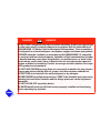
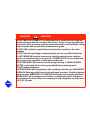
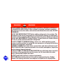
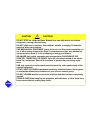
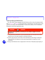
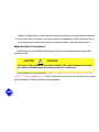
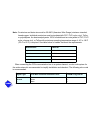
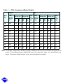
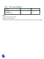
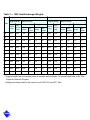
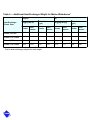
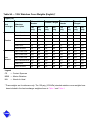
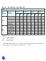
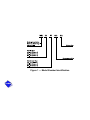
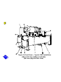
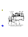
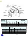
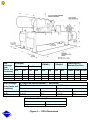
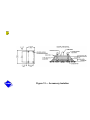
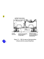
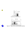
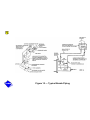
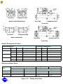
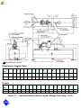
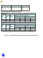
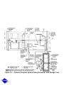
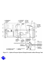
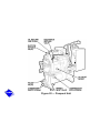
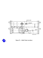
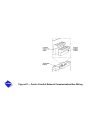
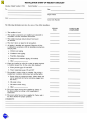
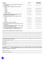
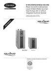
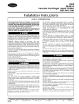
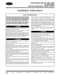
®
19XL
50/60 Hz
Hermetic Centrifugal Liquid Chillers
with HCFC–22 and HFC–134a
Installation Instructions
For Units Produced After 11/1/92 (Linear Float Design)
Manufacturer reserves the right to discontinue, or change at any time, specifications or designs without notice and
without incurring obligations.
Catalog No. 531-944
9-94
Form 19XL-3SI
Replaces: 19XL-2SI
Copyright © Carrier Corporation 1994
Safety Considerations
Centrifugal liquid chillers are designed to provide safe and reliable service when
operated within design specifications. When operating this equipment, use good
judgement and safety precautions to avoid damage to equipment and property or injury
to personnel.
Be sure you understand and follow the procedures and safety precautions contained
in the machine instructions, as well as those listed in this guide.
DANGER
!
DANGER
DO NOT VENT refrigerant relief devices within a building. Outlet from rupture disc
or relief valve must be vented outdoors in accordance with the latest edition of
ANSI/ASHRAE 15 (Safety Code for Mechanical Refrigeration). The accumulation
of refrigerant in an enclosed space can displace oxygen and cause asphyxiation.
PROVIDE adequate ventilation in accordance with ANSI/ASHRAE 15, especially
for enclosed and low overhead spaces. Inhalation of high concentrations of vapor
is harmful and may cause heart irregularities, unconsciousness, or death. Intentional misuse can be fatal. Vapor is heavier than air and reduces the amount of
oxygen available for breathing. Product causes eye and skin irritation. Decomposition products are hazardous.
DO NOT USE OXYGEN to purge lines or to pressurize a machine for any purpose.
Oxygen gas reacts violently with oil, grease, and other common substances.
DO NOT USE air to leak test. Use only refrigerant or dry nitrogen.
NEVER EXCEED specified test pressures. VERIFY the allowable test pressure by
checking the instruction literature and the design pressures on the equipment
nameplate.
DO NOT VALVE OFF any safety device.
BE SURE that all pressure relief devices are properly installed and functioning
before operating any machine.
WARNING
!
WARNING
DO NOT WELD OR FLAMECUT any refrigerant line or vessel until all refrigerant
((liquid and vapor) has been removed from chiller. Traces of vapor should be displaced with dry air or nitrogen and the work area should be well ventilated. Refrigerant in contact with an open flame produces toxic gases.
DO NOT USE eyebolts or eyebolt holes to rig machine sections or the entire
assembly.
DO NOT work on high-voltage equipment unless you are a qualified electrician.
DO NOT WORK ON electrical components including control panels, switches,
starters, or oil heater until you are sure ALL POWER IS OFF and no residual voltage can leak from capacitors or solid-state components.
LOCK OPEN AND TAG electrical circuits during servicing. IF WORK IS INTERRUPTED, confirm that all circuits are generalized before resuming work.
DO NOT siphon refrigerant.
AVOID SPILLING liquid refrigerant on skin or getting it into the eyes. USE SAFETY
GOGGLES. Wash any spills from the skin with soap and water. If liquid refrigerant
enters the eyes, IMMEDIATELY FLUSH EYES with water and consult a physician.
NEVER APPLY an open flame or live steam to a refrigerant cylinder. Dangerous
over pressure can result. When it is necessary to heat refrigerant, use only warm
(110 F [43 C]) water.
WARNING
!
WARNING
DO NOT REUSE disposable (nonreturnable) cylinders or attempt to refill them. It
is DANGEROUS AND ILLEGAL. When cylinder is emptied, evacuate remaining
gas pressure, loosen the collar, and unscrew and discard the valve stem. DO NOT
INCINERATE.
CHECK THE REFRIGERANT TYPE before adding refrigerant to the machine. The
introduction of the wrong refrigerant can cause machine damage or malfunction.
Operation of this equipment with refrigerants other than those cited herein should
comply with ANSI/ASHRAE-15 (latest edition). Contact Carrier for further information on use of this machine with other refrigerants.
DO NOT ATTEMPT TO REMOVE fittings, covers, etc., while machine is under
pressure or while machine is running. Be sure pressure is at 0 psig (0 kPa) before
breaking any refrigerant connection.
CAREFULLY INSPECT all relief valves, rupture discs, and other relief devices AT
LEAST ONCE A YEAR. If machine operates in a corrosive atmosphere, inspect the
devices at more frequent intervals.
DO NOT ATTEMPT TO REPAIR OR RECONDITION any relief valve when corrosion
or build-up of foreign material (rust, dirt, scale, etc.) is found within the valve
body or mechanism. Replace the valve.
DO NOT install relief devices in series or backwards.
USE CARE when working near or in line with a compressed spring. Sudden
release of the spring can cause it and objects in its path to act as projectiles.
CAUTION
!
CAUTION
DO NOT STEP on refrigerant lines. Broken lines can whip about and release
refrigerant, causing personal injury.
DO NOT climb over a machine. Use platform, catwalk, or staging. Follow safe
practices when using ladders.
USE MECHANICAL EQUIPMENT (crane, hoist, etc.) to lift or move inspection covers or other heavy components. Even if components are light, use mechanical
equipment when there is a risk of slipping or losing your balance.
BE AWARE that certain automatic start arrangements CAN ENGAGE THE
STARTER, TOWER FAN, OR PUMPS. Open the disconnect ahead of the starter,
tower fan, and pumps. Shut off the machine or pump before servicing equipment.
USE only repaired or replacement parts that meet the code requirements of the
original equipment.
DO NOT VENT OR DRAIN waterboxes containing industrial brines, liquid, gases,
or semisolids without the permission of your process control group.
DO NOT LOOSEN waterbox cover bolts until the waterbox has been completely
drained.
DOUBLE-CHECK that coupling nut wrenches, dial indicators, or other items have
been removed before rotating any shafts.
CAUTION
!
CAUTION
DO NOT LOOSEN a packing gland nut before checking that the nut has a positive
thread engagement.
PERIODICALLY INSPECT all valves, fittings, and piping for corrosion, rust, leaks,
or damage.
PROVIDE A DRAIN connection in the vent line near each pressure relief device to
prevent a build-up of condensate or rain water.
Contents
List of Tables
List of Figures
Safety Considerations
Introduction
General
Job Data
Equipment Required
Installation
Receiving the Machine
Inspect Shipment
Identify Machine
Provide Machine Protection
Rigging the Machine
Rig Machine Assembly
Contents
Rig Machine Components
Install Machine Supports
Install Standard Isolation
Install Optional Isolation
Install Spring Isolation
Connect Piping
Install Water Piping to Heat Exchangers
Install Vent Piping to Relief Devices
Make Electrical Connections
Connect Control Inputs
Connect Control Outputs
Connect Starter
Carrier Comfort Network Interface
Install Field Insulation
Installation Start-Up Request Checklist
Contents
List of Tables
Table 1
— 19XL Compressor/Motor Weights
Table 2
— 19XL Component Weights
Table 3
— 19XL Heat Exchanger Weights
Table 4
— Additional Heat Exchanger Weight for Marine Waterboxes
Table 5
— 19XL Waterbox Cover Weights
Table 6
— Relief Device Locations
Contents
List of Figures
Figure 1 — Model Number Identification
Figure 2 — Typical 19XL Installation (300 to 600 Tons [1055 to 2110 kW])
Figure 3 — Machine Rigging Guide
Figure 4 — 19XL Dimensions
Figure 5 — 19XL Condenser Drain
Figure 6 — 19XL Motor End View
Figure 7 — 19XL Machine Top View
Figure 8 — 19XL Refrigerant Return
Figure 9 — 19XL Oil Reclaim System
Figure 10 — 19XL Machine Footprint
Figure 11 — Standard Isolation
Figure 12 — Accessory Isolation
Figure 13 — 19XL Accessory Spring Isolation (Shown with Accessory
Soleplates)
Contents
Figure 14 — Typical 19XL Low Profile Isolation Assembly
Figure 15 — Typical Nozzle Piping
Figure 16 — Piping Flow Data
Figure 17 — Optional Pumpout System and/or Storage Tank
Figure 18 — Optional Pumpout System Piping Schematic with Storage
Tank
Figure 19 — Optional Pumpout System Piping Schematic without
Storage Tank
Figure 20 — Pumpout Unit
Figure 21 — Relief Valve Locations
Figure 22 — Carrier Comfort Network Communication Bus Wiring
Figure 23 — COMM1 CCN Communication Wiring for Multiple Chillers
(Typical)
Figure 24 — 19XL with Optional Unit-Mounted Starter
Figure 25 — 19XL with Freestanding Starter
Contents
Figure 26 — 19XL Typical Field Wiring with Optional Unit-Mounted
Starter
Figure 27 — 19XL Typical Field Wiring with Free-Standing Starter
Figure 28 — Oil Pump Wiring
Figure 29 — Oil Heater and Control Power Wiring
Figure 30 — 19XL Insulation Area
Introduction
General
The 19XL machine is factory assembled, wired, and leak tested. Installation (not by Carrier)
consists primarily of establishing water and electrical services to the machine. The rigging,
installation, field wiring, field piping and insulation of waterbox covers are the responsibility of
the contractor and/or customer. Carrier has no installation responsibilities for the equipment.
Job Data
Necessary information consists of:
•
•
•
•
•
•
•
job contract or specifications
machine location prints
rigging information
piping prints and details
field wiring drawings
starter manufacturer’s installation details
Carrier certified print
Equipment Required
•
•
•
•
•
mechanic’s tools (refrigeration)
volt-ohmmeter and clamp-on ammeter
leak detector (halide or electronic)
absolute pressure manometer or wet-bulb vacuum indicator
portable vacuum pumps
Installation
Receiving the Machine
Inspect Shipment
CAUTION
!
CAUTION
Do not open any valves or loosen any connections. The standard 19XL machine
is shipped with a full refrigerant charge. Some machines may be shipped with a
nitrogen holding charge as an option.
1. Inspect for shipping damage while machine is still on shipping conveyance. If machine
appears to be damaged or has been torn loose from its anchorage, have it examined by
transportation inspectors before removal. Forward claim papers directly to transportation
company. Manufacturer is not responsible for any damage incurred in transit.
2. Check all items against shipping list. Immediately notify the nearest Carrier representative if
any item is missing.
3. To prevent loss or damage, leave all parts in original packages until beginning installation.
All openings are closed with covers or plugs to prevent dirt and debris from entering
machine components during shipping. A full operating oil charge is placed in the oil sump
before shipment.
Identify Machine
The machine model number, serial number, and heat exchanger sizes are stamped on
machine identification nameplate (Figure 1, Figure 2 (Front View) (Rear View). Check this
information against shipping papers and job data.
Click here for Figure 1 — Model Number Identification
Provide Machine Protection
Protect machine and starter from construction dirt and moisture. Keep protective shipping
covers in place until machine is ready for installation. If machine is exposed to freezing
temperatures after water circuits have been installed, open waterbox drains and remove all
water from cooler and condenser. Leave drains open until system is filled.
Click here for Figure 2 (Front and Rear Views) — Typical 19XL Installation
(300 to 600 Tons [1055 to 2110 kW])
Rigging the Machine
The 19XL machine can be rigged as an entire assembly. It also has flanged connections that
allow the compressor, cooler, and condenser sections to be separated and rigged individually.
Rig Machine Assembly
See rigging instructions on label attached to machine. Also refer to rigging guide Figure 3,
physical data in Figure 4, and Table 1, Table 2, Table 3, Table 4, Table 5A and Table 5B. Lift
machine only from the 3 points indicated in rigging guide. Each lifting cable or chain must be
capable of supporting the entire weight of the machine.
WARNING
!
WARNING
Lifting machine from points other than those specified may result in serious damage to the unit and personal injury. Rigging equipment and procedures must be
adequate for machine weight. See Table 1, Table 2, Table 3, Table 4, Table 5A, and
Table 5B for machine weights.
Note: These weights are broken down into component sections for use when
installing the unit in sections. For the complete machine weight, add all component sections and refrigerant charge together. See Table 1, Table 2, Table 3,
Table 4, Table 5A, and Table 5B for machine component weights.
IMPORTANT: Make sure that rigging cable is over the rigging bar before lifting.
Rig Machine Components
Refer to instructions below, Figure 5, Figure 6, Figure 7, Figure 8, Figure 9, and Carrier
Certified Prints for machine component disassembly.
IMPORTANT: Only a qualified service technician should perform this operation.
WARNING
!
WARNING
Do not attempt to disconnect flanges while the machine is under pressure. Failure
to relieve pressure can result in personal injury or damage to the unit.
CAUTION
!
CAUTION
Before rigging the compressor, disconnect all wires entering the power panel.
Note: If the cooler and condenser vessels must be separated, the heat exchanger separation
feet can be unbolted, slipped down, and re-bolted in order to keep each heat exchanger
level. See Figure 3.
Note: Wiring must also be disconnected. Label each wire before removal (see Carrier Certified
Prints). In order to disconnect the starter from the machine, remove wiring for the oil
pump, oil heater, control wiring at the power panel, and the main motor leads at the
starter lugs.
Remove all transducer and sensor wires at the sensor. Clip all wire ties necessary to pull
heat exchangers apart.
Click here for Figure 3 — Machine Rigging Guide
Click here for Figure 4 — 19XL Dimensions
Click here for Table 1 — 19XL Compressor/Motor Weights
Click here for Table 2 — 19XL Component Weights
Click here for Table 3 — 19XL Heat Exchanger Weights
Click here for Table 4 — Additional Heat Exchanger Weight for Marine Waterboxes*
Click here for Table 5A — 19XL Waterbox Cover Weights* (English, lb.)
Click here for Table 5B — 19XL Waterbox Cover Weights* (SI, kg)
To Separate Cooler and Condenser
1. Turn vessel separation feet into lowered position (Figure 5, Item 1).
2. Disconnect the flared fitting on the refrigerant motor cooling line at the isolation valve
(Figure 6, Item 3).
3. Disconnect the condenser discharge line at the compressor (Figure 6, Item 1).
4. Cut the hot gas bypass line on the cooler side of the isolation valve (not shown).
5. Cut cooler liquid feed line at location indicated (Figure 5, Item 2).
6. Cover all openings.
7. Disconnect the wires and cable housings which cross from the starter to the power panel at
the power panel (Figure 7, Item 8).
8. Disconnect the rabbet-fit connectors on the tube sheets (Figure 7, Item 7).
9. Rig vessels apart.
To Separate the Compressor from the Cooler
1. Unbolt suction elbow at the cooler flange (Figure 7, Item 11).
2. Disconnect the flared fitting on the refrigerant motor cooling line at the isolation valve
(Figure 6, Item 3).
3. Cut the refrigerant return line from the oil cooler (Figure 6, Item 2).
4. Disconnect the motor refrigerant return line (Figure 8, Item 1).
5. Disconnect the following (Figure 7):
a. Oil sump sensor cable (Item 5).
b. Bearing sensor cable (Item 4).
c. Motor sensor cable (Item 3).
d. Wires and cable housing which cross to the starter and control panel from the power
panel (Items 8 and 9).
e. Discharge sensor cable (Item 6).
f. Oil pressure transducer cable (Item 2).
g. Guide vane actuator cable (Item 10).
6. Disconnect the flared fittings for the oil reclaim lines (Figure 9, Item 1).
7. Unbolt the compressor discharge line (Figure 6, Item 1).
8. Cover all openings.
9. Disconnect motor power cables at the starter lugs (Figure 7, Item 1).
10. Rig compressor.
CAUTION
!
CAUTION
Do not tilt the compressor; oil charge is still contained in the oil sump.
Click here for Figure 5 — 19XL Condenser Drain
Click here for Figure 6 — 19XL Motor End View
Click here for Figure 7 — 19XL Machine Top View
Click here for Figure 8 — 19XL Refrigerant Return
Click here for Figure 9 — 19XL Oil Reclaim System
To Rig Compressor
Note: The motor end of the 19XL compressor is heavy and will tip backwards unless these
directions are followed:
1. Remove rigging bar (Figure 6, Item 4) and the bolts securing it.
2. Place the rigging bar vertically over the compressor end bell (Figure 6, Item 5). Attach the
rigging bar to the compressor end bell using the 2 bolts removed in Step 1.
Additional Notes
1. Use silicon grease on new O-rings when refitting.
2. Use gasket sealant on new gaskets when refitting.
3. Cooler and condenser vessels may be rigged vertically. Rigging should be fixed to all 4
corners of the tube sheet.
Install Machine Supports
Install Standard Isolation
Figure 10 and Figure 11 show the position of support plates and shear flex pads, which
together form the standard machine support system.
Install Accessory Isolation (if required)
Uneven floors or other considerations may dictate the use of accessory soleplates (supplied
by Carrier for field installation) and leveling pads. Refer to Figure 10 and Figure 12.
Level machine by using jacking screws in isolation sole-plates. Use a level at least 24-in.
(600 mm) long.
For adequate and long lasting machine support, proper grout selection and placement is
essential. Carrier recommends that only premixed, epoxy type, non-shrinking grout be used for
machine installation. Follow manufacturer’s instructions in applying grout.
1. Check machine location prints for required grout thickness.
2. Carefully wax jacking screws for easy removal from grout.
3. Grout must extend above the base of the soleplate and there must be no voids in grout
beneath the plates.
4. Allow grout to set and harden, per manufacturer’s instructions, before starting machine.
5. Remove jacking screws from leveling pads after grout has hardened.
Click here for Figure 10 — 19XL Machine Footprint
Click here for Figure 11 — Standard Isolation
Install Spring Isolation
Spring isolation may be purchased as an accessory from Carrier for field installation. It may
also be field supplied and installed. Spring isolators may be placed directly under machine
support plates or located under machine soleplates. See Figure 13. Consult job data for specific
arrangement. Low profile spring isolation assemblies can be field supplied to keep the machine
at a convenient working height (Figure 14).
Obtain specific details on spring mounting and machine weight distribution from job data.
Also, check job data for methods to support and isolate pipes that are attached to spring
isolated machines.
Click here for Figure 12 — Accessory Isolation
Click here for Figure 13 — 19XL Accessory Spring Isolation (Shown with Accessory
Soleplates)
Click here for Figure 14 — Typical 19XL Low Profile Isolation Assembly
Connect Piping
Install Water Piping to Heat Exchangers
Install piping using job data, piping drawings, and procedures outlined below. A typical piping
installation is shown in Figure 15.
CAUTION
!
CAUTION
Factory-supplied insulation is not flammable but can be damaged by welding
sparks and open flame. Protect insulation with a wet canvas cover.
CAUTION
!
CAUTION
Remove chilled and condenser water sensors before welding connecting piping
to water nozzles. Refer to Figure 2. Replace sensors after welding is complete.
1. Offset pipe flanges to permit removal of waterbox cover for maintenance and to provide
clearance for pipe cleaning. No flanges are necessary with marine waterbox option;
however, water piping should not cross in front of the waterbox or access will be blocked.
2. Provide openings in water piping for required pressure gages and thermometers. For
thorough mixing and temperature stabilization, wells in the leaving water pipe should
extend inside pipe at least 2 in. (50 mm).
3. Install air vents at all high points in piping to remove air and prevent water hammer.
4. Install pipe hangers where needed. Make sure no weight or stress is placed on waterbox
nozzles or flanges.
5. Water flow direction must be as specified in Figure 16.
Note: Entering water is always the lower of the 2 nozzles. Leaving water is always the upper
nozzle for cooler or condenser.
6. Water flow switches must be of vapor-tight construction and must be installed on top of pipe
in a horizontal run and at least 5 pipe diameters from any bend.
7. Install waterbox vent and drain piping in accordance with individual job data. All
connections are 3/4 -in. FPT.
8. Install waterbox drain plugs in the unused waterbox drains and vent openings.
9. Install optional pumpout system or pumpout system and storage tank as shown in
Figure 17, Figure 18, Figure 19, and Figure 20.
Figure 15 — Typical Nozzle Piping
Figure 16 — Piping Flow Data
Figure 17 — Optional Pumpout System and/or Storage Tank
Figure 18 — Optional Pumpout System Piping Schematic with Storage Tank
Figure 19 — Optional Pumpout System Piping Schematic without Storage Tank
Figure 20 — Pumpout Unit
Install Vent Piping to Relief Devices
The 19XL chiller is factory equipped with relief devices on the cooler and condenser shells.
Refer to Figure 21 and Table 6 for size and location of relief devices. Vent relief devices to the
outdoors in accordance with ANSI/ASHRAE 15 (latest edition) Safety Code for Mechanical
Refrigeration and all other applicable codes.
DANGER
!
DANGER
Refrigerant discharged into confined spaces can displace oxygen and cause
asphyxiation.
1. If relief devices are manifolded, the cross-sectional area of the relief pipe must at least
equal the sum of the areas required for individual relief pipes.
2. Provide a pipe plug near outlet side of each relief device for leak testing. Provide pipe
fittings that allow vent piping to be disconnected periodically for inspection of valve
mechanism.
3. Piping to relief devices must not apply stress to the device. Adequately support piping. A
length of flexible tubing or piping near the device is essential on spring-isolated machines.
4. Cover the outdoor vent with a rain cap and place a condensation drain at the low point in
the vent piping to prevent water build-up on the atmospheric side of the relief device.
Make Electrical Connections
Field wiring must be installed in accordance with job wiring diagrams and all applicable
electrical codes.
CAUTION
!
CAUTION
Do not run 120-v wiring into the control cabinet. The control cabinet should only
be used for additional extra low-voltage wiring (50 v maximum).
Wiring diagrams in this publication (Figure 22, Figure 23, Figure 24, Figure 25, Figure 26,
Figure 27, Figure 28, and Figure 29) are for reference only and are not intended for use during
actual installation; follow job specific wiring diagrams.
WARNING
!
WARNING
Do not attempt to start compressor or oil pump (even for a rotation check) or
apply test voltage of any kind while machine is under dehydration vacuum. Motor
insulation breakdown and serious damage may result.
Connect Control Inputs
Connect the control input wiring from the chilled and condenser water flow switches to the
starter terminal strip. Wiring may also be specified for a spare safety switch, and a remote start/
stop contact can be wired to the starter terminal strip. Additional spare sensors and Carrier
Comfort Network modules may be specified as well. These are wired to the machine control
panel as indicated in Figure 22 and Figure 23.
Click here for Figure 21 — Relief Valve Locations
Click here for Figure 22 — Carrier Comfort Network Communication Bus Wiring
Click here for Figure 23 — COMM1 CCN Communication Wiring for Multiple Chillers
(Typical)
Connect Control Outputs
Connect auxiliary equipment, chilled and condenser water pumps, and spare alarms as
required and indicated on job wiring drawings.
Connect Starter
The 19XL is available with either a unit-mounted, factory-installed starter or a free-standing,
field-installed starter (Figure 24 and Figure 25).
Unit Mounted, Factory-Installed Starter
Attach power leads by connecting them from inside the starter cabinet to the line side circuit
breaker terminals. See Figure 24 and Figure 26. Machines with electro-mechanical starters
(wye-delta) will have a top hat shipped with the machine if the RLA is greater than 432 amps.
The top hat is shipped in the knocked-down position and must be assembled and installed on
top of the starter cabinet, over the line side circuit breaker. During assembly, remove the access
plate and use it as the cover piece of the top hat. The top hat provides additional wire bending
space to attach line side power leads to the circuit breaker within the starter. The solid-state
starter does not require a top hat.
IMPORTANT: Be sure to ground the power circuit in accordance with the National
Electrical Code (NEC), applicable local codes, and job wiring diagrams. Also, make
sure correct phasing is observed for proper rotation.
Click here for Figure 24 — 19XL with Optional Unit-Mounted Starter
Freestanding, Field-Installed Starter
Assemble and install compressor terminal box in desired orientation, and cut necessary
conduit openings in conduit support plates. See Figure 25 and Figure 27. Attach power leads to
compressor terminals in accordance with job wiring drawings, observing caution label in
terminal box. Use only copper conductors. The motor must be grounded in accordance with
NEC (National Electrical Code), applicable local codes, and job wiring diagrams. Installer is
responsible for any damage caused by improper wiring between starter and compressor motor.
IMPORTANT: Do not insulate terminals until wiring arrangement has been checked and
approved by Carrier start-up personnel. Also, make sure correct phasing is followed
for proper motor rotation.
Insulate Motor Terminals and Lead Wire Ends
Insulate compressor motor terminals, lead wire ends, and electrical wires to prevent moisture
condensation and electrical arcing. For low-voltage units (up to 600 v), obtain insulation
material from machine shipping package consisting of 3 rolls of insulation putty and one roll of
vinyl tape.
1. Insulate each terminal by wrapping with one layer of insulation putty.
2. Overwrap putty with 4 layers of vinyl tape.
High Voltage Units
High-voltage units require special terminal preparation. Follow local electrical codes for highvoltage installation. The vinyl tape is not acceptable, a high voltage terminal methods must be
used.
Connect Power Wires to Oil Pump Starter
See Figure 28. Connect power wires to oil pump starter mounted in machine power panel.
Use separate fused disconnect or circuit breaker as shown on job wiring diagrams and
Figure 27. Check that power supply voltage agrees with oil pump voltage. Follow correct
phasing for proper motor rotation.
CAUTION
!
CAUTION
Do not punch holes or drill into the top surface of the power panel. Knockouts
are provided in the bottom of the power panel for wiring connections.
Click here for Figure 25 — 19XL with Freestanding Starter
Click here for Figure 26 — 19XL Typical Field Wiring with Optional Unit-Mounted
Starter
Click here for Figure 27 — 19XL Typical Field Wiring with Free-Standing Starter
Connect Power Wires to Oil Heater Contactor
Connect power wiring to oil heater contactor using a separate power source and fused
disconnect. Refer to Figure 29 and wiring label on the machine power panel.
Connect Wiring from Starter to Power Panel
Connect control wiring from main motor starter to the machine power panel. All control wiring
must use shielded cable. Also, connect the communications cable. Refer to the job wiring
diagrams for cable type and cable number. Make sure the control circuit is grounded in
accordance with applicable electrical codes and instructions on machine control wiring label.
Click here for Figure 28 — Oil Pump Wiring
Click here for Figure 29 — Oil Heater and Control Power Wiring
Carrier Comfort Network Interface
The Carrier Comfort Network (CCN) communication bus wiring is supplied and installed by
the electrical contractor. It consists of shielded, 3-conductor cable with drain wire.
The system elements are connected to the communication bus in a daisy chain
arrangement. The positive pin of each system element communication connector must be wired
to the positive pins of the system element on either side of it. The negative pins must be wired
to the negative pins. The signal ground pins must be wired to the signal ground pins. See
Figure 22 for location of the CCN network connector (COMM1) on the processor module.
Note: Conductors and drain wire must be 20 AWG (American Wire Gauge) minimum stranded,
tinned copper. Individual conductors must be insulated with PVC, PVC/ nylon, vinyl, Teflon,
or polyethylene. An aluminum/polyester 100% foil shield and an outer jacket of PVC, PVC/
nylon, chrome vinyl, or Teflon with a minimum operating temperature range of -4 F to 140 F
(-20 C to 60 C) is required. See table below for cables that meet the requirements.
Manufacturer
Cable No.
Alpha
2413 or 5463
American
A22503
Belden
8772
Columbia
02525
When connecting the CCN communication bus to a system element, a color code system for
the entire network is recommended to simplify installation and checkout. The following color code
is recommended:
Signal Type
CCN Bus Conductor Insulation Color
COMM1 Plug PIN No.
+
Ground
–
Red
White
Black
1
2
3
If a cable with a different color scheme is selected, a similar color code should be adopted for
the entire network.
At each system element, the shields of its communication bus cables must be tied together. If
the communication bus is entirely within one building, the resulting continuous shield must be
connected to ground at only one single point. See Figure 23. If the communication bus cable exits
from one building and enters another, the shields must be connected to ground at the lightening
suppressor in each building where the cable enters or exits the building (one point only).
To connect the 19XL chiller to the network, proceed as follows (Figure 23):
1. Cut power to the PIC control panel.
2. Remove the COMM1 plug from the processor module.
3. Cut a CCN wire and strip the ends of the RED, WHITE, and BLACK conductors.
4. Using a wirenut, connect the drain wires together.
5. Insert and secure the RED wire to Terminal 1 of the COMM1 plug.
6. Insert and secure the WHITE wire to Terminal 2 of the COMM1 plug.
7. Insert and secure the BLACK wire to Terminal 3 of the COMM1 plug.
8. Mount a terminal strip in a convenient location.
9. Connect the opposite ends of each conductor to separate terminals on the terminal strip.
10. Cut another CCN wire and strip the ends of the conductors.
11. Connect the RED wire to the matching location on the terminal strip.
12. Connect the WHITE wire to the matching location on the terminal strip.
13. Connect the BLACK wire to the matching location on the terminal strip.
Install Field Insulation
CAUTION
!
CAUTION
Protect insulation from weld heat damage and weld splatter. Cover with wet canvas cover during water piping installation.
When installing insulation at the job site, insulate the following components:
•
•
•
•
•
•
•
•
compressor motor
cooler shell
cooler tube sheets
suction piping
motor cooling drain
oil reclaim piping
oil cooler refrigerant side tubing
refrigerant liquid line to cooler
Note: Insulation of the waterbox covers is applied only at the jobsite by the contractor. When
insulating the covers, make sure there is access for removal of waterbox covers for servicing (Figure 30).
Click here for Figure 30 — 19XL Insulation Area
Click here for 19XL Installation Start-up Request Checklist CL-1, CL-2 (Print and use
for job file)
Table 1 — 19XL Compressor/Motor Weights
English
Motor
Size
Compressor
Weight
(lb)
SI
Stator
Weight (lb)
Rotor
Weight (lb)
60
Hz
50
Hz
60
Hz
50
Hz
End
Bell
Cover
(lb)
Compressor
Weight
(kg)
Stator
Weight (kg)
Rotor
Weight (kg)
60
Hz
50
Hz
60
Hz
50
Hz
End
Bell
Cover
(kg)
CB
2660
1135
1147
171
233
250
1208
515
520
78
106
114
CC
2660
1143
1150
197
239
250
1208
218
522
90
109
114
CD
2660
1153
1213
234
252
250
1208
523
551
106
114
114
CE
2660
1162
1227
237
255
250
1208
528
557
108
116
114
CL
2660
1202
1283
246
270
250
1208
546
582
112
123
114
CM
2660
1225
1308
254
275
250
1208
556
594
115
125
114
CN
2660
1276
1341
263
279
250
1208
579
609
119
127
114
CP
2660
1289
1356
266
284
250
1208
585
616
121
129
114
CQ
2660
1306
1363
273
287
250
1208
593
619
124
130
114
CR
2660
1335
1384
282
294
250
1208
606
628
128
133
114
Note: For medium voltage motors add 85 lbs (39 kg) to above for 60-Hz motors and 145 lbs (66 kg) for 50-Hz
motors. Total compressor/motor weight is the sum of the compressor, stator, rotor, and end bell cover
weight. Compressor weight includes suction and discharge elbow weights.
Table 2 — 19XL Component Weights
Component
lb
kg
Suction Elbow*
Discharge Elbow*
Control Cabinet†
Optional Mounted Starter**
554
546
530
500
225
221
214
227
Legend
*Included in total compressor weight.
†Included in total cooler weight.
**Weight of optional factory-mounted starter is not included and must be added to heat exchanger weights.
Table 3 — 19XL Heat Exchanger Weights
English
SI
Rigging Wt (lb)*
Code
Cooler
Only
Condenser
Only
40
5154
41
Machine Charge
Refrigerant (lb)†
Rigging Wt (kg)*
Water (gal.)
Cooler
Only
Condenser
Only
Cooler
Condenser
Cooler
Condenser
4643
1920
350
153
156
2340
5275
4771
1990
350
158
162
42
5418
4909
1050
350
164
43
5577
5064
1100
350
50
6730
6413
1300
51
6927
6584
52
7140
53
Machine Charge
Refrigerant (kg)†
Water (L)
Cooler
Condenser
Cooler
Condenser
2108
417
159
200
212
2395
2166
449
159
219
235
168
2460
2229
476
159
242
257
171
175
2532
2299
499
159
269
284
350
179
184
3055
2912
590
159
299
318
1350
350
187
192
3145
2989
612
159
329
348
6780
1430
350
196
101
3242
3078
649
159
363
382
7359
7005
1500
350
104
110
3341
3180
681
159
394
416
55
8220
8008
1840
490
104
112
3728
3632
835
222
394
424
56
8517
8260
1910
490
115
123
3863
3746
866
222
435
466
57
8836
8560
2020
490
128
135
4007
3882
916
222
485
511
58
9164
8900
2120
490
140
119
4156
4037
961
222
530
564
* Rigging weights are for standard tubes of standard wall thickness. For special tubes refer to the 19XL
Computer Selection Program.
† Refrigerant charge listed is the same for both HCFC-22 and HFC-134a.
Table 4 — Additional Heat Exchanger Weight for Marine Waterboxes*
English
Heat Exchanger
Frame, Pass
SI
Rigging Wt (lb)
Water Volume
(gal.)
Rigging Wt (kg)
Water Volume
(gal.)
Cooler
Condenser
Cooler
Condenser
Cooler
Condenser
Cooler
Condenser
Frame 4, 2 Pass
1115
1660
169
151
1506
300
261
193
Frame 4,1 & 3 Pass
2030
1160
138
101
1922
527
524
384
Frame 5, 2 Pass
1220
1935
188
164
1554
424
331
243
Frame 5,1 & 3 Pass
2240
1705
175
128
1017
771
663
486
*Add to heat exchanger weights for total weight.
Table 5A — 19XL Waterbox Cover Weights (English)*
English (Lb)
Heat
Exchanger
Coolers
Condensers
Frame 4, Std
Nozzles
Frame 4, Flanged
Frame 5, Std
Nozzles
Frame 5,
Flanged
150
psig
300
psig
150
psig
300
psig
150
psig
300
psig
150
psig
300
psig
NIH, 1 Pass Cover
284
414
324
491
412
579
452
655
NIH, 2 Pass Cover
285
411
341
523
410
573
466
685
NIH, 3 Pass Cover
292
433
309
469
423
602
440
638
NIH, Plain End Cover
243
292
243
292
304
426
3044
426
MWB Cover
CS
621
CS
621
CS
766
CS
766
Plain End Cover
CS
482
CS
482
CS
471
CS
471
NIH, 1 Pass Cover
306
446
346
523
373
472
413
549
NIH, 2 Pass Cover
288
435
344
547
368
469
428
541
NIH, 3 Pass Cover
319
466
336
502
407
493
419
549
NIH, Plain End Cover
226
271
226
271
271
379
271
379
MWB Cover
CS
474
CS
474
CS
590
CS
590
Plain End Cover
CS
359
CS
359
CS
428
CS
428
Waterbox
Description
Legend
CS
— Contact Syracuse
MWB — Marine Waterbox
NIH
— Nozzle-In-Head
* These weights are for reference only. The 150 psig (1034 kPa) standard waterbox cover weights have
been included in the heat exchanger weights shown in Table 3 and Table 4.
Table 5B — 19XL Waterbox Cover Weights (SI)*
SI (kg)
Heat
Exchanger
Coolers
Condensers
Frame 4, Std
Nozzles
Frame 4,
Flanged
Frame 5, Std
Nozzles
Frame 5,
Flanged
1034
kPa
2068
kPa
1034
kPa
2068
kPa
1034
kPa
2068
kPa
1034
kPa
2068
kPa
NIH, 1 Pass Cover
129
188
148
223
187
262
205
297
NIH, 2 Pass Cover
129
187
155
237
186
260
212
311
NIH, 3 Pass Cover
133
197
140
213
192
273
200
290
NIH, Plain End Cover
110
133
110
133
138
193
138
193
MWB Cover
CS
282
CS
282
CS
348
CS
348
Plain End Cover
CS
219
CS
219
CS
214
CS
214
NIH, 1 Pass Cover
139
202
157
237
169
214
188
249
NIH, 2 Pass Cover
131
197
156
248
167
213
194
246
NIH, 3 Pass Cover
145
212
153
228
185
224
190
249
NIH, Plain End Cover
103
123
103
123
123
172
123
172
MWB Cover
CS
215
CS
215
CS
268
CS
268
Plain End Cover
CS
163
CS
163
CS
194
CS
194
Waterbox
Description
Legend
CS
— Contact Syracuse
MWB — Marine Waterbox
NIH
— Nozzle-In-Head
* These weights are for reference only. The 150 psig (1034 kPa) standard waterbox cover weights have
been included in the heat exchanger weights shown in Table 3 and Table 4.
Table 6 — Relief Device Locations
Relief Valve Outlet Size
Location
Quantity
1-in. NPT
Female Connector
Cooler
1
1-in. NPT
Female Connector
Condenser
2
1-in. NPT
Female Connector
Optional Storage Tank
2
Figure 1 — Model Number Identification
Figure 2 (Front View) — Typical 19XL Installation
(300 to 600 Tons [1055 to 2110 kW])
(See next page for Rear View)
Figure 2 (Rear View) — Typical 19XL Installation
(300 to 600 Tons [1055 to 2110 kW])
Center of Gravity — Approximate Dimensions
A (Length)
B (Width)
C (Height)
Maximum Rigging
Weight (Without
Refrigerant Charge)
Ft-in.
mm
Ft-in.
mm
Ft-in.
mm
lb
kg
40 to 43 (Frame 4)
5-5
1689
2-8
813
3-5
1040
21,200
19,616
50 to 53 (Frame 5)
5-5
1689
2-8
813
3-5
1040
26,400
11,975
55 to 58 (Frame 5)
7-9
2362
2-8
813
3-5
1040
30,850
14,000
Heat Exchanger
(Cooler and
Condenser) Size
Chain Length
Vessel Length
“B”
“C”
“D”
ft-in.
mm
ft-in.
mm
ft-in.
mm
ft-in.
mm
12-3
3734
12-0
3658
12-10
3912
12-10
3912
12-3
3734
12-0
3658
12-10
3912
12-10
3912
17-0
5182
13-9
4166
14-10
4521
14-10
4521
Figure 3 — Machine Rigging Guide
Heat
Exchanger
Code
(Cooler and
Condenser)
A (Length)
ft-in.
mm
ft-in.
40-43
50-53
55-58
13-7 3/4
13-8
18-4 1/2
4159
4166
5601
14-3 1/4 4350
14-3 3/4 4362
19-0 1/4 5798
2 Pass*
Heat Exchanger
Code (Cooler and
Condenser)
40-53
55-58
1 or 3 Pass†
mm
B (Width)
C (Height)
Nozzle Size (in.)
(Nominal Pipe Size)
ft-in.
mm
ft-in.
mm
1-Pass 2-Pass 3-Pass
5-5 3/4
6-0 1/4
6-0 1/4
1670
1835
1835
6-8 5/8
7-2 1/8
7-2 1/8
2048
2188
2188
10
10
10
8
8
8
A (Length with Marine Waterbox — Not Shown)
2 Pass*
1 or 3 Pass†
ft-in.
mm
ft-in.
mm
14-9 5/8
19-6 1/8
4512
5947
16-5 1/2
21-5 1/2
5017
6541
Motor Service Clearance D
ft-in.
mm
4-0
1219
Figure 4 — 19XL Dimensions
6
6
6
Figure 5 — 19XL Condenser Drain
Figure 6 — 19XL Motor End View
Figure 7 — 19XL Machine Top View
Figure 8 — 19XL Refrigerant Return
Figure 9 — 19XL Oil Reclaim System
Heat Exchanger (Cooler/
Condenser)
A
B
ft-in.
mm
ft-in.
mm
40-43
5-5 3/4
1670
13-0 1/4
3968
50-53
6-0 1/4
1835
13-0 1/4
3968
55-58
6-0 1/4
1835
17-8 3/4
5404
Figure 10 — 19XL Machine Footprint
Figure 11 — Standard Isolation
Figure 12 — Accessory Isolation
Figure 13 — 19XL Accessory Spring Isolation
(Shown with Accessory Soleplates)
Figure 14 — Typical 19XL Low Profile Isolation Assembly
Figure 15 — Typical Nozzle Piping
Drive End
Compressor End
Nozzle-in-Head Waterboxes
Drive End
Compressor End
Front View
Drive End
Compressor End
Marine Waterboxes
Drive End
Compressor End
Front View
Nozzle Arrangement Codes
Cooler Waterboxes
Condenser Waterboxes
Pass
In
Out
Arrangement Code
In
Out
Arrangement Code
1
8
5
A
11
12
P
5
8
B
12
11
Q
7
9
C
10
12
R
4
6
D
11
13
S
7
6
E
10
13
T
4
9
F
11
12
U
2
3
Waterbox Nozzle Sizes
Nominal Pipe Size (in.)
Actual Pipe ID (in.)
Actual Pipe OD (in.)
Pass
Cooler
Condenser
Cooler/Condenser
1
10
10
10,020
10,750
2
18
18
17,981
18,625
3
16
16
16,065
16,625
Figure 16 — Piping Flow Data
Denotes center of gravity
Dimensions—English (ft-in.)
Tank
Size
A
B
C
D
E
F
G
H
J
K
L
M
N
P
R
S
T
0428
10-5
9-10
4-9
24 3/4
12 3/8
210 3/4
4-11
38 1/8
3-6
29 7/16
3-2
03 1/2
48 3/4
17 7/8
17 5/16
37 3/4
5-4
0452
1411 1/4
144 1/2
50 7/8
28 1/2
14 1/4
3-2
72 1/4
4-0
311 7/8
31 5/16
35 7/8
03 3/8
71 1/2
18 3/4
17 9/16
3-8
54 1/4
SI (mm)
Tank
Size
A
B
C
D
E
F
G
H
J
K
L
M
N
P
R
S
T
0428
3175
2997
1448
730
365
883
1499
1121
1067
849
965
89
1442
505
491
1111
1626
0452
4553
4382
1546
826
413
965
2191
1219
1216
948
1064
86
2172
528
497
1118
1632
Figure 17 — Optional Pumpout System and/or Storage Tank (Page 1 of 2)
QTY
Trade Size
Location
1
1
1
1
1/2”
3/4”
1”
1 1/4”
top
bottom
middle
middle
Rated Dry Weight and Refrigerant Capacity
English (lb)
Tank
Size
0428
0452
Dry
Tank OD
Weight*
(in.)
(lb)
24.00
27.25
2200
3270
Maximum Refrigerant Capacity (lb)
ASHRAE 15
ARI 495
(HCFC-22)
(HFC-134a) (HCFC-22)
(HFC-134a)
1840
3525
2025
3880
1810
3465
1645
3155
SI (kg)
Tank
Size
0428
0452
Dry
Tank OD
Weight*
(mm)
(kg)
610
592
1998
1606
Maximum Refrigerant Capacity (kg)
ASHRAE 15
ARI 495
(HCFC-22)
(HFC-134a) (HCFC-22)
(HFC-134a)
1835
1599
1928
1760
1822
1572
1747
1431
Figure 17 — Optional Pumpout System and/or Storage Tank (Continued)
Figure 18 — Optional Pumpout System Piping Schematic with Storage Tank
Figure 19 — Optional Pumpout System Piping Schematic without Storage Tank
Figure 20 — Pumpout Unit
Figure 21 — Relief Valve Locations
Figure 22 — Carrier Comfort Network Communication Bus Wiring
Figure 23 — COMM1 CCN Communication Wiring For Multiple Chillers (Typical)
Figure 24 — 19XL With Optional Unit-Mounted Starter
Figure 25 — 19XL With Freestanding Starter
LEGEND
AWG
NO
NC
PR
RLA
ST
TB
—
—
—
—
—
—
—
—
—
—
American Wire Gage
Normally Open
Normally Closed
Pilot Relay
Rated Load Amps
Shunt Trip
Terminal Block
Required Power Wiring
Required Control Wiring
Options Wiring
Figure 26 — 19XL Typical Field Wiring with Optional Unit-Mounted Starter
LEGEND
— Required Power Wiring
— Required Control Wiring
— Options Wiring
Figure 27 — 19XL Typical Field Wiring with Free-Standing Starter
Figure 28 — Oil Pump Wiring
Figure 29 — Oil Heater and Control Power Wiring
Figure 30 — 19XL Insulation Area