1
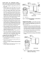
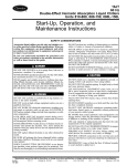
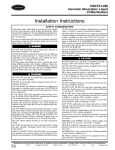
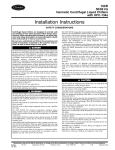
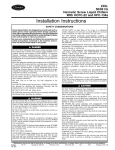
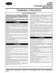
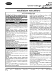
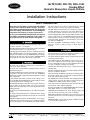
16JT810-880, 080-150, 080L-150L
Double-Effect
Hermetic Absorption Liquid Chillers
Installation Instructions
SAFETY CONSIDERATIONS
Absorption liquid chillers provide safe and reliable
service when operated within design specifications. When operating this equipment, use good judgment and safety precautions to avoid damage to
equipment and property or injury to personnel.
Be sure you understand and follow the procedures
and safety precautions contained in the chiller instructions as well as those listed in this guide.
DO NOT USE OXYGEN or air to purge lines, leak test, or
pressurize a chiller. Use nitrogen.
NEVER EXCEED specified test pressures. For the 16JT chiller,
the maximum pressure is 12 psig (83 kPa).
WEAR goggles and suitable protective clothing when handling lithium bromide, octyl alcohol, inhibitor, lithium hydroxide, and hydrobromic acid. IMMEDIATELY wash any
spills from the skin with soap and water. IMMEDIATELY
FLUSH EYES with water and consult a physician.
DO NOT USE eyebolts or eyebolt holes to rig chiller sections or the entire assembly.
DO NOT work on high-voltage equipment unless you are a
qualified electrician.
DO NOT WORK ON electrical components, including control panels or switches, until you are sure ALL POWER IS
OFF and no residual voltage can leak from capacitors or solidstate components.
LOCK OPEN AND TAG electrical circuits during servicing. IF WORK IS INTERRUPTED, confirm that all circuits
are deenergized before resuming work.
NEVER DISCONNECT safety devices or bypass electric interlocks while operating the chiller. Also, never operate the
chiller when any safety devices are not adjusted and functioning normally.
DO NOT syphon lithium bromide or any other chemical by
mouth.
BE SURE all hydrogen has been exhausted before cutting
into purge chambers. Hydrogen mixed with air can explode
when ignited.
WHEN FLAMECUTTING OR WELDING on an absorption chiller, some noxious fumes may be produced. Ventilate
the area thoroughly to avoid breathing concentrated fumes.
DO NOT perform any welding or flamecutting to a chiller
while it is under a vacuum or pressurized condition.
NEVER APPLY an open flame or live steam to a refrigerant
cylinder. Dangerous overpressure can result. When necessary to heat a cylinder, use only warm (110 F [43 C]) water.
DO NOT REUSE disposable (nonreturnable) cylinders or attempt to refill them. It is DANGEROUS AND ILLEGAL.
When cylinder is emptied, evacuate remaining gas pressure,
loosen the collar, and unscrew and discard the valve stem.
DO NOT INCINERATE.
DO NOT ATTEMPT TO REMOVE fittings, covers, etc.,
while the chiller is under pressure or while chiller is
running.
DO NOT climb over a chiller. Use platform, catwalk, or staging. Follow safe practices when using ladders.
DO NOT STEP ON chiller piping. It might break or bend
and cause personal injury.
USE MECHANICAL EQUIPMENT (crane, hoist, etc.) to
lift or move inspection covers or other heavy components.
Even if components are light, use such equipment when there
is a risk of slipping or losing your balance.
VALVE OFF AND TAG steam, water, or brine lines before
opening them.
DO NOT LOOSEN waterbox cover bolts until the water box
has been completely drained.
DO NOT VENT OR DRAIN waterboxes containing industrial brines, liquid, gases, or semisolids without permission
from your process control group.
BE AWARE that certain automatic start arrangements can
engage starters. Open the disconnects ahead of the starters
in addition to shutting off the chiller or pump.
USE only repaired or replacement parts that meet the code
requirements of the original equipment.
DO NOT ALLOW UNAUTHORIZED PERSONS to tamper
with chiller safeties or to make major repairs.
PERIODICALLY INSPECT all valves, fittings, piping, and
relief devices for corrosion, rust, leaks, or damage.
PROVIDE A DRAIN connection in the vent line near each
pressure relief device to prevent a build-up of condensate or
rain water.
IMMEDIATELY wipe or flush the floor if lithium bromide
or octyl alcohol is spilled on it.
Manufacturer reserves the right to discontinue, or change at any time, specifications or designs without notice and without incurring obligations.
Book 2
PC 211
Catalog No. 531-611
Printed in U.S.A.
Form 16JT-3SI
Pg 1
8-96
Replaces: 16JT-2SI
Tab 5b
If the last five digits of the serial number are 80XXX (where
XXX stands for the last three digits of the serial number),
the model comes with fusible plug drain piping and rupture
disc piping; if the last five digits are 92XXX, the model comes
with rupture disc piping only.
CONTENTS
Page
SAFETY CONSIDERATIONS . . . . . . . . . . . . . . . . . . . 1
INTRODUCTION . . . . . . . . . . . . . . . . . . . . . . . . . . . . . . 2
General . . . . . . . . . . . . . . . . . . . . . . . . . . . . . . . . . . . . . . 2
Job Data . . . . . . . . . . . . . . . . . . . . . . . . . . . . . . . . . . . . 2
RECEIVING THE CHIILLER . . . . . . . . . . . . . . . . . . . 2,3
Identify Chiller . . . . . . . . . . . . . . . . . . . . . . . . . . . . . . . 2
Inspect Shipment . . . . . . . . . . . . . . . . . . . . . . . . . . . . 2
One-Piece Chillers: Check Shipping
Vacuum . . . . . . . . . . . . . . . . . . . . . . . . . . . . . . . . . . . 2
Two-Piece Chillers: Check Shipping
Pressure . . . . . . . . . . . . . . . . . . . . . . . . . . . . . . . . . . 2
Provide Chiller Protection . . . . . . . . . . . . . . . . . . . . 2
RIGGING AND POSITIONING . . . . . . . . . . . . . . . . . 3-8
Rig One-Piece Units . . . . . . . . . . . . . . . . . . . . . . . . . . 3
Rig Two-Piece Units . . . . . . . . . . . . . . . . . . . . . . . . . . 3
• PREPARATION
• RIGGING
Position and Level the Equipment . . . . . . . . . . . . 8
CHIILLER ASSEMBLY . . . . . . . . . . . . . . . . . . . . . . . 8-10
Assemble Two-Piece Units . . . . . . . . . . . . . . . . . . . 8
Purge Exhaust Assembly . . . . . . . . . . . . . . . . . . . . . 8
Chiller Leak Test . . . . . . . . . . . . . . . . . . . . . . . . . . . . . 8
Chiller Evacuation . . . . . . . . . . . . . . . . . . . . . . . . . . . 8
Connect Water Piping . . . . . . . . . . . . . . . . . . . . . . . . 9
Install Steam and Condensate Piping . . . . . . . . 10
Fusible Plug Drain Piping . . . . . . . . . . . . . . . . . . . 10
Rupture Disc Piping . . . . . . . . . . . . . . . . . . . . . . . . . 10
INSULATION AND PAINT . . . . . . . . . . . . . . . . . . . . . 11
Insulation (If Required) . . . . . . . . . . . . . . . . . . . . . . 11
• COLD SURFACES
• HOT SURFACES
Final Paint Coat (If Required) . . . . . . . . . . . . . . . . 11
CONTROLS AND WIRING . . . . . . . . . . . . . . . . . . . . 11
Two-Piece Chiller Connections . . . . . . . . . . . . . . . 11
Chillers With Electro-Mechanical Controls . . . . 11
• CAPACITY CONTROL VALVE(S)
• EXTERNAL WIRING
• SENSOR ELEMENTS
Chillers With PIC Controls . . . . . . . . . . . . . . . . . . . 11
• CAPACITY CONTROL VALVE(S)
• EXTERNAL WIRING
• SENSOR ELEMENTS
INITIAL SOLUTION AND REFRIGERANT
CHARGING . . . . . . . . . . . . . . . . . . . . . . . . . . . . . . . 12
Fig. 1 — Model Number Nomenclature
For 16JT chillers sizes 810 to 880, the evaporator and absorber are located side by side; for sizes 080 to 150 and 080L
to 150L, the evaporator is located above the absorber.
Inspect Shipment (Fig. 2) — One-piece chillers are
at a deep vacuum when shipped. Do not open any valves
until the vacuum has been noted. Refer to One-Piece Chillers: Check Shipping Vacuum below.
NOTE: Chillers shipped in 2 pieces are under nitrogen
pressure.
Inspect for shipping damage while chiller is still on shipping conveyance. If chiller appears to be damaged or has
been torn loose from its anchorage, have it examined by transportation inspectors before removal. Forward claim papers
directly to transportation company. Manufacturer is not responsible for any damage incurred in transit.
Check all items against shipping list. Immediately notify
the nearest Carrier Air Conditioning office if any item is
missing.
To prevent loss or damage, leave all parts in original packages until installation.
One-Piece Chillers: Check Shipping Vacuum —
To check for leaks that have occurred during shipment on
one-piece chillers:
1. Connect an absolute pressure gage to a service valve.
2. Record the absolute pressure of the assembly. If the vessel pressure is greater than 0.28 in. (7 mm) of mercury,
the chiller has acquired a leak in shipping and must be
leak tested. Refer to the Chiller Leak Test section for
instructions.
INTRODUCTION
Two-Piece Chillers: Check Shipping Pressure
— To check for leaks that have occurred during shipment
General — The 16JT chiller is factory assembled, wired,
and leak tested. Installation (not by Carrier) consists primarily of establishing water, steam, and electrical services to
the chiller. Rigging, installation, insulation, field wiring, and
field piping are the responsibility of the contractor and/or
customer. Carrier has no installation responsibilities for the
equipment.
on two-piece chillers:
1. Connect a pressure gage (30 psig [200 kPa]) to a service
valve on each piece. Two-piece chillers are pressurized
with nitrogen to 5 psig (34 kPa).
2. If the vessel has lost its pressure, it has acquired a leak
during shipping and must be leak tested after positioning
and assembly. Refer to the Chiller Leak Test section for
instructions.
Job Data — Necessary information consists of chiller location drawings, piping drawings, field wiring diagrams, and
a rigging guide.
Provide Chiller Protection — If the chiller will not
be installed immediately, it is very important to use a drop
cloth or plastic cover to protect the chiller from construction
dirt and moisture before installation. Also, do not remove protective shipping cover on control panel until ready to use.
RECEIVING THE CHIILLER
Identify Chiller — The chiller model number and serial
number are stamped on the chiller identification plate. Check
this information against shipping papers and job data. For
information on model number nomenclature, see Fig. 1.
The 16JT comes with either electro-mechanical controls
or Product Integrated Controls (PIC), depending on when it
was manufactured.
2
16JT SIZES 810-880
2
3
4
1
1
2
3
4
5
6
7
8
9
5
—
—
—
—
—
—
—
—
—
LEGEND
High-Stage Generator
Low-Stage Generator (Hidden)
Condenser
Purge Storage Chamber
Control Panel
Nameplate (On Support Leg)
Solution Heat Exchangers
Absorber
Evaporator
9
8
6
7
16JT SIZES 080-150, 080L-150L
3
4
5
6
2
7
1
13
8
1 — High-Stage Generator
2 — Hot Vapor Line from the High-Stage
Generator
3 — Low-Stage Generator (Hidden)
4 — Condenser
5 — Control Panel
6 — Purge Storage Chamber
7 — Auxiliary Evacuation Valve
8 — Refrigerant Sump Box
9 — Nameplate
10 — Refrigerant Pump
11 — Solution Heat Exchanger
12 — Absorber
13 — Evaporator
12
9
10
11
Fig. 2 — Chiller Components
PREPARATION — Two-piece units must be prepared for
installation before they can be rigged. Refer to Fig. 7-10.
1. Open the auxiliary evacuation valves to relieve pressure
in the absorber-evaporator shell.
2. Open the shipping valve on the generator-condenser assembly to relieve pressure.
RIGGING AND POSITIONING
Rigging procedures vary depending on whether the chiller
is shipped in one or 2 pieces.
Lifting the chiller from points other than those specified
may result in serious damage and personal injury. Rigging equipment and procedures must be adequate for
chiller weights and sizes. Refer to Tables 1 and 2 for
chiller weights, and Fig. 3 and 4 for overall dimensions.
To keep foreign particles out of the chiller, do not leave
chiller open any longer than necessary.
Rig One-Piece Units (Fig. 5) — Lift the entire assembly with cable slings placed under the lower shell, as
shown in Fig. 5, to distribute and balance the weight.
Do not remove any stock from pipe ends. Do not get
slag inside chiller while flamecutting.
Rig Two-Piece Units (Fig. 6)
3. Remove all piping end plates by flamecutting the end plate,
and weld the flange around each outer diameter as shown
in Fig. 7. Cut these pieces, as shown in Fig. 8, for proper
reconnection.
4. Grind the cut pieces smooth for a close fit when the chiller
pieces are assembled.
If the chiller is assembled before it is rigged, to avoid
damage to the chiller, do not lift under the generator
shell or waterboxes. The chiller should be lifted under
the absorber-evaporator shell.
3
DIMENSIONS (ft-in.)
UNIT 16JT
Overall Length
Overall Width
Overall Height
Height
A
B
C
D*
810
9-10
6- 4
7- 7
7- 2
812
9-10
6- 4
7- 7
7- 2
814
9-10
6- 4
7- 7
7- 2
816
13-7
6-2
7-7
7-2
818
13-7
6-2
7-7
7-2
821
13-7
6-2
7-7
7-2
824
13-8
6-7
8-2
7-6
828
13-8
6-7
8-2
7-6
UNIT 16JT
Overall Length A
Overall Width B
Overall Height C
Height
D*
836
17-6
6-6
8-4
7-1
841
17- 8
6-11
9- 1
7- 5
847
17- 8
6-11
9- 1
7- 5
854
17- 8
7- 4
9- 9
7-10
857
22-11
6-11
9- 8
8- 1
865
22-11
6-11
9- 8
8- 1
873
22-11
7- 4
9- 5
7- 8
880
23- 2
7- 7
9-11
7-11
832
17-6
6-6
8-4
7-1
DIMENSIONS (mm)
UNIT 16JT
Overall Length A
Overall Width B
Overall Height C
Height
D*
810
3000
1930
2310
2185
812
3000
1930
2310
2185
814
3000
1930
2310
2185
816
4140
1880
2310
2185
818
4140
1880
2310
2185
821
4140
1880
2310
2185
824
4165
2005
2490
2285
828
4165
2005
2490
2285
UNIT 16JT
Overall Length A
Overall Width B
Overall Height C
Height
D*
836
5335
1980
2540
2160
841
5385
2110
2770
2260
847
5385
2110
2770
2260
854
5385
2235
2970
2390
857
6985
2110
2950
2460
865
6985
2110
2950
2460
873
6985
2235
2870
2335
880
7060
2310
3020
2415
832
5335
1980
2540
2160
*Standard shipping configuration for sizes 810-880 is one-piece.
Dimension ‘‘D’’ is height of absorber-evaporator section for two-piece shipment. Removal of purge storage tank may reduce height further.
NOTES:
1. All dimensions are approximate and do not take into account absorber-condenser crossover piping if not factory installed as standard.
2. For routine maintenance, allow 3 ft (1 m) clearance on all sides and 6 in. (150 mm) above chiller.
3. For service access, allow clearances as follows:
a. For tube removal, allow space to equal ‘‘A’’ dimension (length) at either end of the chiller.
b. For opening waterbox cover, allow space equal to half of ‘‘B’’ dimension (width) at end of chiller opposite nozzle.
Fig. 3 — Dimensions, 16JT810-880
4
DIMENSIONS (ft-in.)
UNIT 16JT
Overall Length A
Overall Width B
Overall Height C
Height
D*
080
23- 0
8- 5
9-10
7-10
090
23-0
8-3
10-5
8-4
100
23- 0
8-10
11- 0
8- 9
110
23-3
9-2
11-7
9-4
120
23- 3
9- 7
12- 3
9-10
135
23-6
10-1
13-0
10-7
150
23-6
10-8
13-8
11-2
UNIT 16JT
Overall Length A
Overall Width B
Overall Height C
Height
D*
080L
25-11
8- 5
9-10
7-10
090L
25-11
8- 3
10- 5
8- 4
100L
26- 0
8-10
11- 0
8- 9
110L
26-2
9-2
11-7
9-4
120L
26- 2
9- 7
12- 3
9-10
135L
26-6
10-1
13-0
10-7
150L
26-6
10-8
13-8
11-2
DIMENSIONS (mm)
UNIT 16JT
Overall Length A
Overall Width B
Overall Height C
Height
D*
080
7010
2565
3000
2390
090
7010
2515
3175
2540
100
7010
2690
3350
2665
110
7085
2795
3530
2845
120
7085
2920
3735
3000
135
7160
3075
3960
3225
150
7160
3250
4165
3405
UNIT 16JT
Overall Length A
Overall Width B
Overall Height C
Height
D*
080L
7900
2565
3000
2390
090L
7900
2515
3175
2540
100L
7925
2690
3350
2665
110L
7975
2795
3530
2845
120L
7975
2920
3735
3000
135L
8075
3075
3960
3225
150L
8075
3250
4165
3405
*Standard shipping configuration for sizes 080-100 is one-piece, sizes 110-150 and 080L-150L are 2-piece.
Dimension ‘‘D’’ is height of absorber-evaporator section for two-piece shipment. Removal of purge storage tank may reduce height further.
NOTES:
1. All dimensions are approximate and do not take into account absorber-condenser crossover piping if not factory installed as standard.
2. For routine maintenance, allow 3 ft (1 m) clearance on all sides and 6 in. (150 mm) above chiller.
3. For service access, allow clearances as follows:
a. For tube removal, allow space to equal ‘‘A’’ dimension (length) at either end of the chiller.
b. For opening waterbox cover, allow space equal to half of ‘‘B’’ dimension (width) at end of chiller opposite nozzle.
Fig. 4 — Dimensions, 16JT080-150, 080L-150L
5
Table 1 — Rigging Weights, One-Piece Shipment*
UNIT
16JT
810
812
814
816
818
821
824
828
832
836
841
847
854
857
865
873
880
080
090
100
110
120
135
150
080L
090L
100L
110L
120L
135L
150L
Table 2 — Rigging Weights, Two-Piece Shipment*
WEIGHT
WEIGHT
lb
11,680
11,900
12,120
16,090
16,310
16,530
16,970
17,410
20,275
20,935
23,365
24,025
26,450
31,740
32,400
35,265
38,135
44,080
49,590
54,440
59,505
66,120
71,630
77,140
50,695
56,865
60,610
65,020
71,405
83,755
87,060
UNIT
16JT
kg
5 300
5 400
5 500
7 300
7 400
7 500
7 700
7 900
9 200
9 500
10 600
10 900
12 000
14 400
14 700
16 000
17 300
20 000
22 500
24 700
27 000
30 000
32 500
35 000
23 000
25 800
27 500
29 500
32 400
38 000
39 500
810
812
814
816
818
821
824
828
832
836
841
847
854
857
865
873
880
080
090
100
110
120
135
150
080L
090L
100L
110L
120L
135L
150L
*Standard shipping configuration for sizes 810-880 and 080-100 is one piece.
(Two-piece shipment for these sizes is optional.)
Standard shipping configuration for sizes 110-150 and 080L-150L is two pieces.
(One-piece shipment for these sizes is optional.)
Absorber/Evaporator
lb
kg
8,595
3 900
8,815
4 000
9,035
4 100
11,460
5 200
11,680
5 300
11,680
5 300
11,900
5 400
12,120
5 500
13,885
6 300
14,325
6 500
16,090
7 300
16,530
7 500
18,295
8 300
22,040
10 000
22,480
10 200
23,005
10 800
26,010
11 800
29,755
13 500
34,160
15 500
37,470
17 000
41,875
19 000
47,385
21 500
51,795
23 500
55,100
25 000
35,265
16 000
40,335
18 300
42,980
19 500
45,845
20 800
50,690
23 000
59,510
27 000
62,845
28 500
Generator/Condenser
lb
kg
3,085
1 400
3,085
1 400
3,085
1 400
4,630
2 100
4,630
2 100
4,850
2 200
5,070
2 300
5,290
2 400
6,390
2 900
6,610
3 000
7,275
3 300
7,495
3 400
8,155
3 700
9,700
4 400
9,920
4 500
11,460
5 200
12,125
5 500
14,325
6 500
15,430
7 000
16,970
7 700
17,630
8 000
18,735
8 500
19,835
9 000
22,040
10 000
15,430
7 000
16,530
7 500
17,630
8 000
19,175
8 700
20,715
9 400
24,245
11 000
24,245
11 000
*Standard shipping configuration for sizes 810-880 and 080-100 is one piece.
(Two-piece shipment for these sizes is optional.)
Standard shipping configuration for sizes 110-150 and 080L-150L is two pieces.
(One-piece shipment for these sizes is optional.)
Fig. 5 — Rigging One-Piece Units
Fig. 6 — Rigging Two-Piece Units
6
Fig. 8 — Flamecutting and Welding Detail
Fig. 7 — Weld Breaking and Weld Connection
Instructions
1
2
3
4
5
—
—
—
—
—
6
7
8
9
—
—
—
—
1
2
3
4
5
6
7
8
9
10
11
Weak solution to high-stage generator
Strong solution from high-stage generator
Weak solution from level control box
Weak solution to level control box
Strong solution from high-temperature heat exchanger to
low-stage generator
Strong solution overflow from low-stage generator
Strong solution from low-stage generator
Purge line (condenser to absorber)
Refrigerant from condenser
—
—
—
—
—
—
—
—
—
—
—
Weak solution from level control box
Weak solution to high-stage generator
Strong solution from high-stage generator
Weak solution to level control box
Cooling water connection (absorber to condenser)
Refrigerant from condenser
Purge line (condenser to absorber)
Refrigerant from condenser
Strong solution from high-temperature heat exchanger
Strong solution from low-stage generator
Strong solution overflow from low-stage generator
Fig. 10 — Chiller Configuration
16JT080-150, 080L-150L
Fig. 9 — Chiller Configuration
16JT810-880
7
RIGGING — The 2 pieces are the generator-condenser shell
assembly and the absorber-evaporator shell assembly.
1. Lift each assembly with cable slings placed under the shells,
as shown in Fig. 6, to distribute and balance the weight.
2. Position and level the absorber-evaporator assembly first.
See Position and Level the Equipment section.
3. Move the generator-condenser assembly to the top of the
absorber-evaporator assembly. Match connecting piping
for the generator-condenser and absorber-evaporator
assemblies. Make sure stamped serial numbers accompanying the match marks correspond on both assemblies.
Purge Exhaust Assembly — Install the purge exhaust assembly on the purge exhaust valve as shown in
Fig. 12.
Position and Level the Equipment — Isolation pads
are not necessary for most installations. However, for cases
where isolation pads are required, refer to Fig. 11 for typical
installation.
It is not necessary to level the generator-condenser
assembly, because both assemblies are designed to be level
when the absorber-evaporator assembly has been leveled.
The 16JT chiller must be level within 1⁄4 in. per 20 ft
(6.3 mm per 6 m), both lengthwise and diagonally. To level
the absorber-evaporator, proceed as follows:
1. Completely fill a 50-ft (15 m) length of clear flexible tubing with water.
2. Use the water gage and leveling reference points stamped
on the absorber-evaporator shell to level the absorberevaporator.
3. Level the absorber-evaporator with shims until requirements are met. If an isolation assembly is used, shim under the soleplate.
4. Set anchor bolts with concrete to secure absorberevaporator in place.
Fig. 12 — Purge Exhaust Assembly
Chiller Leak Test — All field-welded joints on the chiller
must be leak tested before starting the chiller. Leak test as
follows:
1. Close all external service valves.
2. If the chiller is under vacuum, bring it to atmospheric pressure with dry nitrogen.
3. Pressurize to 6 psig (40 kPa) with tracer gas. Charge through
the auxiliary evacuation valve.
4. Increase the chiller pressure to 12 psig (83 kPa) with dry
nitrogen.
Exceeding 12 psi (83 kPa) can cause severe damage to
the chiller.
5. Leak test all field-welded joints with electronic leak detectors or equivalent. If the chiller has acquired a leak in
shipment or rigging, all joints must be leak tested.
6. After leak testing has been completed and leaks have been
repaired, release the chiller pressure.
Chiller Evacuation — Noncondensables must be removed from the chiller after the chiller has been opened. To
evacuate the chiller, proceed as follows:
1. Connect an auxiliary evacuation device (Fig. 13) to the
auxiliary evacuation valve. Be sure that the line is as short
as possible and that the line size is not smaller than the
connection to the auxiliary device. Use a check valve or
oil trap on the suction lines to keep vacuum pump oil out
of the chiller. Be sure that all connections are vacuum
tight.
2. Close the external service valve(s).
3. Start the auxiliary evacuation device. Open the auxiliary
evacuation valve. Reduce chiller pressure to 1 in. (25 mm)
of mercury absolute or lower. Check pressure with an absolute pressure gage at the refrigerant pump service valve.
NOTES:
1. Be sure only the chiller base is on the isolation pad.
2. Shim under soleplate to level chiller.
Fig. 11 — Typical Isolation Assembly
CHIILLER ASSEMBLY
No assembly is required for one-piece units.
Assemble Two-Piece Units
1. Weld the piping connections as shown in Fig. 7-10. Make
sure the weld connections are vacuum leak tight.
2. Cut shipping braces between upper shell assemblies.
8
Fig. 13 — Auxiliary Evacuation Device
4. Close the auxiliary evacuation valve and shut off the auxiliary evacuation device.
5. Note and record the absolute pressure gage reading.
6. Coat all chiller field-welded joints with weld sealant.
Connect Water Piping — Install piping using job data,
piping drawings, and procedures outlined below. Figure 14
shows a typical piping schematic.
1. Make sure all connections to the waterbox covers allow
the covers to be opened for maintenance.
2. Installation and piping should allow sufficient access for
cleaning or replacing tubes.
3. Install pipe hangers where needed. Make sure no weight
or stress is placed on the waterbox nozzles or flanges.
P
PRIMARY STEAM
SUPPLY
STEAM PRESSURE
REDUCING VALVE
V2
3-WAY
BYPASS
VALVE
T5 P5
ABSORPTION CHILLER
V5
P7
P6
V4
V3
BLEED-OFF-VALVE
4. Water flow direction must be as specified in the job flow
diagrams or water flow markings on waterboxes. Make
connections to the correct entering and leaving waterbox
nozzles.
5. Install waterbox vent and drain piping in accordance with
individual job data. Air vents should be at all high points
in piping to eliminate water hammer.
6. Location of the chilled water and cooling water pumps,
as well as the expansion tank, must allow for the hydrostatic and water heads to ensure that the total pressure
does not exceed the waterbox design working pressure.
7. Install a 3-way cooling tower 3-way bypass valve if the
cooling water temperature might fall below 59 F (15 C)
during chiller operation.
8. Install thermometer wells and thermometers on the entering and leaving chilled water pipes (Fig. 14, Items T1
and T2), absorber entering and leaving cooling water pipes
(Fig. 14, Items T3 and T4), and condenser leaving cooling water pipe (Fig. 14, Item T5). Thermometer wells should
extend into the pipe a minimum of 1⁄3 the pipe diameter.
9. Install pressure gage taps and pressure gages on the entering and leaving chilled water pipes (Fig. 14, Items P1
and P2), on the entering and leaving absorber cooling water pipes (Fig. 14, Items P3 and P4), and the cooling water pipe leaving the condenser (Fig. 14, Item P5).
COOLING TOWER
RUPTURE
DISC
CONDENSER
GENERATOR
EXPANSION TANK
T4
P4
T2 P2
V1
STEAM TRAP
CAPACITY CONTROL
STEAM VALVE
V7
ABSORBER EVAPORATOR
V6
T1 P1
CHILLED
WATER PUMP
DRAIN
TANK
TO BOILER
CONDENSATE
RETURN
DRAIN
V — Valve
T3 P3
CHILLED
WATER PUMP
Steam Strainer
Pressure Gage
3-Way Bypass Valve
Thermometer
Steam Pressure Reducing Valve
Manual Valve
Water Pump
Relief Valve
Optional Piping
Check Valve
Fig. 14 — Typical Piping Schematic
9
BUILDING
LOAD
Install Steam and Condensate Piping —
Figure 14 shows a typical piping schematic. Refer to job data
and certified drawings for data specific to your installation.
1. Make sure connections to the steam box cover (see
Fig. 5 and 6) allow for removal of the cover for
maintenance.
2. Install pipe hangers where needed. Make sure no weight
or stress is placed on the steam chest cover (see Fig. 5
and 6), nozzle, or on the condensate drain connection.
3. Locate the capacity control steam valve at least
3 ft (1 m) from the generator nozzle. For inspection and
maintenance, a bypass line with a manual valve (Fig. 14,
Item V1) should be installed around the capacity control
valve. Also, a manual shut-off valve (V2) should be installed ahead of the capacity control steam valve. Install
isolation valves (Fig. 14, Item V3 and V4) on the inlet
and outlet sides of the capacity control steam valve. Piping must allow for thermal expansion and slope slightly
toward the generator for condensate drainage.
4. Two pressure gages (Fig. 14, Items P6 and P7) with a
pressure range of 0 to 200 psig (0 to 1400 kPa) should be
installed before and after the capacity control steam valve.
5. If the primary steam supply pressure is above 125 psig
(862 kPa), install a steam pressure reducing valve between the primary steam supply and the capacity control
steam valve inlet (Fig. 14). Install a bypass valve around
the steam pressure reducing valve, a steam strainer on the
inlet side of the steam pressure reducing valve, and isolation valves around the pressure reducing valve.
6. If the steam supply pressure to the generator can exceed
114 psig (786 kPa), a safety relief valve (Fig. 14, Item
V5) must be installed between the capacity control steam
valve and the generator to limit the pressure to 114 psig
(786 kPa). The safety relief valve should be vented to the
outside of the building for safety.
7. Install steam condensate drain piping so that the back pressure at the connection to the chiller is less than
7 psig (48 kPa) to prevent condensate back-up into the
generator tubes at low load conditions. Include a check
valve (Fig. 14, Item V6) and manual shut-off valve
(Fig. 14, Item V7) at the condensate drain outlet.
*R.F. — Raised Face.
Fig. 15 — Rupture Disc Location on Chillers With a
Fusible Plug
Rupture Disc Piping — 16JT chillers are factory
equipped with a rupture disc assembly on the condenser shell.
Chillers with fusible drain piping have a 2-in. rupture disc
(Fig. 15); chillers without fusible drain piping have a 3-in.
rupture disc (Fig. 16).
Vent rupture discs to the outside of the building for safety.
1. Add a flexible connection and adequate support to the pipe,
as required, to eliminate any piping stress on the rupture
disc. Provide fittings so vent piping can be disconnected
periodically for inspection of the disc. Provide a pipe plug
on the outlet side of the relief device for leak testing.
2. Cover the outdoor vent with a rain cap to prevent excessive moisture from entering the vent line.
3. Place a condensate drain at the low point in the piping to
prevent water build-up on the atmospheric side of the disc
assembly.
Fusible Plug Drain Piping (Fig. 15) — For 16JT
chillers with fusible plug drain piping:
1. Connect drain piping to discharge the hot refrigerant water to a safe area.
2. Do not loosen or disconnect the fusible plug while connecting the relief pipe to it.
3. Make sure connections to the fusible plug are threaded
and allow easy pipe removal for leak tests and
maintenance.
4. Install pipe hangers where needed to be sure that no weight
or stress is placed on the fusible plug.
*R.F. — Raised Face.
Fig. 16 — Rupture Disk Location on Chillers
Without a Fusible Plug
10
EXTERNAL WIRING — Install external wiring to the chiller
control panel according to job wiring diagrams and data. Check
available power supply and safety interlocks to be sure they
match the chiller equipment requirements, including:
• three-phase power supply for controls and chiller hermetic pumps
• start and run interlocks for chilled water and cooling water pumps and for cooling tower fan(s)
• remote chiller start/stop contacts, if used
• remote operating status and fault indication, if used.
SENSOR ELEMENTS — For all sensor elements not already installed on the chiller, uncoil the capillary tubing for
the thermoswitches and place the sensing element in the adjacent temperature wells. Add heat conductive oil or compound to the wells after checking and calibrating the following controls at start-up:
• absorber solution temperature limit switch
• high-stage generator/high-temperature limit switch
• low chilled water temperature limit switch
• low refrigerant temperature limit switch or other temperature switches when used
• water pressure differential switch (normally installed in the
field). Since there is no bulb, the pressure is tapped to the
water piping.
INSULATION AND PAINT
Insulation (If Required) — Apply insulation as indicated in the job data, after the chiller assembly and field piping have been completed. If the shipping vacuum or pressure test indicate possible leakage, do not apply insulation
until the leak has been corrected. Protect insulation from weld
heat damage and weld splatter during installation. Recommended areas for insulation include:
COLD SURFACES
• entering and leaving chilled water lines
• evaporator waterboxes and covers (be sure to allow for
easy cover removal)
• refrigerant pump casing and its inlet and outlet piping
• evaporator shell and tube sheets, including refrigerant sump
box
HOT SURFACES
• steam and condensate lines
• drain heat exchanger and piping
• generator steam chest. Be sure to allow for easy cover
removal.
• high-stage generator shell, tube sheets, and float chamber
• high-temperature heat exchanger and strong solution piping from high-stage generator
• hot refrigerant vapor inlet and hot refrigerant water outlet
on the low-stage generator and the vapor line from the highstage generator. Large chillers (models 080-150 and 080L150L) have 2 hot refrigerant vapor inlets and 2 hot refrigerant water outlets.
Chillers with PIC Controls
CAPACITY CONTROL VALVE(S) — Refer to the job control diagrams and instructions for specific connections. The
chilled water temperature sensor and its wiring to the control panel are installed in the factory. Install wiring for the
valve positioning control between the valve operator and the
wiring terminals in the control panel. Wire the 4 to 20 mA
signal for the valve operator to terminal strip 1 (TB-1), terminals 415 (+) and 416 (−). The 4 to 20 mA signal is internally powered.
Electronically Controlled Actuator — Also install wiring for
valve operator power between the valve operator and wiring
terminals in the control panel.
Pneumatically Controlled Actuator — Also install 1⁄4-in.
(6 mm) plastic tubing between the valve operator and the
pneumatic supply air.
EXTERNAL WIRING — Install external wiring to chiller
control panel according to job wiring diagrams and data. Check
available power supply and safety interlocks to be sure they
match the chiller equipment requirements, including:
• three-phase power supply for controls and chiller hermetic pumps
• start and run interlocks for chilled water and cooling water pumps and for cooling tower fan(s)
• remote chiller start/stop contacts, if used
• remote operating status and fault indication, if used
• any CCN wiring as indicated on the job wiring diagrams.
SENSOR ELEMENTS — For all sensor elements not already installed on the chiller, uncoil the capillary tubing for
the thermoswitches and place the sensing element in the adjacent temperature wells. Add heat conductive oil or compound to the wells after checking and calibrating the following controls at start-up:
• high-stage generator/high-temperature limit switch
• low chilled water temperature limit switch
• water pressure differential switch (normally installed in the
field). Since there is no bulb, the pressure is tapped to the
water piping.
Final Paint Coat (If Required) — Paint the chiller as
indicated in the job data after installation assembly, leak testing, and insulation have been completed. Use specified paint,
making sure only high-temperature paint is applied to areas
with hot surfaces, as described above.
CONTROLS AND WIRING
The 16JT chiller has either Product Integrated Controls
(PIC) or electro-mechanical controls (electronic or pneumatic). Field wiring and pneumatic connections must be installed in accordance with job wiring diagrams and all applicable codes.
Two-Piece Chiller Connections — Reconnect any
control wiring and conduit that had been disconnected at the
factory for shipping the chiller in 2 pieces.
Chillers With Electro-Mechanical Controls
CAPACITY CONTROL VALVE(S) —The controls can be
either electronic or pneumatic (Fig. 17). Refer to the job control diagrams and instructions for specific connections. The
chilled water temperature sensor and its wiring to the control panel are installed in the factory. Install wiring for the
valve positioning control between the valve operator and the
wiring terminals in the control panel.
Electronically Controlled Actuator — Also install wiring for
valve operator power between the valve operator and wiring
terminals in the control panel.
Pneumatically Controlled Actuator — Also install 1⁄4-in.
(6 mm) plastic tubing between the valve operator and the
pneumatic supply air.
11
INITIAL SOLUTION AND
REFRIGERANT CHARGING
Lithium bromide solution and refrigerant (water) will be
placed in the chiller at initial start-up. Do not charge solution into chiller until the unit is ready for operation.
Do not start any pump motors until the chiller has been
charged with solution and refrigerant. The hermetic pumps
can be seriously damaged by dry operation.
See 16JT Start-Up, Operation, and Maintenance instructions for charging procedures.
Fig. 17 — Capacity Controls
Copyright 1996 Carrier Corporation
Manufacturer reserves the right to discontinue, or change at any time, specifications or designs without notice and without incurring obligations.
Book 2
PC 211
Catalog No. 531-611
Printed in U.S.A.
Form 16JT-3SI
Pg 12
8-96
Replaces: 16JT-2SI
Tab 5b