1
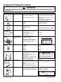
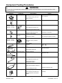
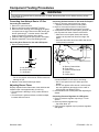
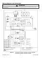
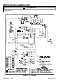
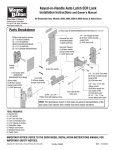
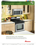
Amana Technical InformationGas Range ARGS7650 P1130752N, P1130755N, P1130756N, P1130757N, P1130758N, P1130759N, P1130760N, P1130761N, P1130762N, P1130764N, P1130765N, P1130766N • Due to possibility of personal injury or property damage, always contact an authorized technician for servicing or repair of this unit. • This technical sheet replace RT2310003 Rev. 9. • Refer to Service Manual RS2310002 for detailed installation, operating, testing, troubleshooting, and disassembly instructions. • Refer to Parts Manual RP2310032, RP2310045 and RP2310054 for part number information. ! CAUTION All safety information must be followed as provided in Service Manual RS2310002. ! WARNING To avoid risk of electrical shock, personal injury, or death, disconnect power to oven before servicing, unless testing requires it. Models Power Source Electrical rating Amperage Frequency Water Column Pressure Natural LP/Propane Surface Burner (BTU Nat./LP) Small Medium Two large Oven Burner (BTU Nat./LP) Bake Insta-Broil Oven Interior Dimensions in. (cm) Height Width Depth Product Exterior Dimensions in. (cm) Height overall Width Depth oven door closed with handle Clearance oven door Weight lbs. (kg) Approximately shipping weight Features High performance die cast sealed burners Exclusive one-piece cast iron burner grates Frameless glass door with window Interior oven light Two oven racks5 positions Exclusive Insta-Broil system Removable full width storage drawer Self-cleaning porcelain oven with autolatch December 2000 ARGS7650 120 VAC 15 Amp maximum 60 Hz 6 in. W.C.P. 10 in. W.C.P. 5,000/4,000 9,100/8,000 12,500/10,000 15,500/15,500 14,000/13,000 16 (41) 23 (58) 17 1/2 (44) 36 (119) 30 1/8 (76) 23 (72) 20 (51) 171 (78) X X X X X X X X 1 RT2310003 Rev. 10 Component Testing Procedures ! WARNING To avoid risk of electrical shock, personal injury, or death, disconnect power to oven before servicing, unless testing requires it. Illustration 31823701 Component Oven light socket Test Procedure Remove one wire from receptacle and test resistance of terminals. Measure voltage at oven light. 0301491 Rocker switch 0305797 Door plunger switch NC C NO 0316767 Door lock switch NC NO COM 31797301 31933401 Autolatch assembly with door plunger switch Results Indicates continuity with bulb screwed in. 120 VAC, see wiring diagram for terminal identification. If no voltage is present at oven light, check wiring or light switches. Measure continuity of switch positions: Closed Open Continuity, if not replace. Infinite, if not replace. Remove switch from unit and measure the following points: C-NC C NO Plunger in infinite, Plunger out continuity. Plunger in continuity, Plunger out infinite. Test for voltage at terminals to chassis when in bake, broil, or clean mode. COM to chassis Only when latch is engaged: NC to chassis 120 VAC 120 VAC Disconnect wires and test for continuity per diagram. L1 L2 Refer to Parts Manual for correct autolatch switch associated with the correct manufacturing number. NC NC COM NO COM NO M 120 VAC Lock/Unlock Switch Motor 31933003 31933004 31715201−LH 31715202−RH Limits Hinge Opening 309145−Broil 31939901-Broil 316223−Bake 31940001-Bake Norton ignitor 0300664 Dual thermal valve Oven limit Closed Open See wiring diagram. 210°F 240°F Fan limit Closed Open Carefully open the hinge fully, and insert a wooden dowel or screwdriver bit into opening. Remove top and bottom screws securing hinge. Slide hinge top towards rear of unit and guide hinge out through frame opening or storage drawer. 155°F 115°F ! Door Switch CAUTION Do not place hands in hinge area when oven door is removed. Hinge can snap closed and pinch hands or fingers. Test for voltage at terminals. 120 VAC Test for the amount of amperage in the circuit. (Ignitor may glow but not have sufficient amperage to open valve). 3.2 − 3.6 Amps If not replace. Disconnect wiring to valve. Measure resistance on bake circuit. Measure resistance on broil circuit. Continuity, If not replace. Continuity, If not replace. ! WARNING Do not attempt to open valve with 120 VAC. RT2310003 Rev. 10 2 December 2000 Component Testing Procedures ! WARNING To avoid risk of electrical shock, personal injury, or death, disconnect power to oven before servicing, unless testing requires it. Illustration 0042303 Component Pressure regulator Test Procedure Verify gas pressure (W.C.P.). Results 6" Natural 10" LP/propane If on LP service verify proper gas supply conversion. 0301361 Shut off valve Check to verify gas supply is turned on. 0315960 5 K btu 0315961 9 K btu 0315962 12 K btu 270° valve Verify gas is supplied. 0316572 Spark 270° switch H R G AA 0316773 Orifice adjusted for Natural or LP. Spark ignition electrode 0315769 5 K btu 0315768 9 K btu 0315767 12 K btu Top surface burner L Spark module 4 + 0 A 120 VAC Disconnect wiring and check for continuity in LITE position. Test for resistance of spark lead. Continuity in LITE position. Test ignitor to chassis. No continuity from ignitor to chassis. Verify gas is supplied. Check for obstructions in burner ports. Continuity Verify burner cap is positioned correctly. Venturi 0315154 Adjust set screw for simmer control. Test for voltage at terminals. Shutter settings Nominal Tol. ± .125" 1/8" .031" 1/32" Test for voltage at terminals L and N. B 120 VAC See wiring diagram Check polarity and ground. N A1 B1 0314907All others 31968201P1130766N Temperature sensor Measure resistances. 31716501 Bake burner Verify gas is supplied. Approximately 1100 Ω at room temperature 75°F. Orifice adjusted for Natural or LP. 0060691 Broil burner Check for obstructions or contamination in ports. Verify gas is supplied. Proper orifice installed for Natural or LP. Replace if punctured or torn. Check for damage to screen. 308607 December 2000 ERC cooling blower Verify supply voltage. 120 VAC Check continuity of terminals, and verify terminals are not shorted to chassis. Continuity 3 RT2310003 Rev. 10 Component Testing Procedures ! WARNING To avoid risk of electrical shock, personal injury, or death, disconnect power to oven before servicing, unless testing requires it. Illustration 0315569 31944801 OVEN CANCEL TIMER ON/OFF DELAY OVEN ON CLEAN STOP TIME CLOCK STOP TIME BAKE BROIL CLEAN LOCK COOK TIME CLEAN BROIL Component ERC3 - Touchmatic electronic range control O N BAKE ERC3 Controlled Quick test ERC3 Controlled Oven temperature adjustment ERC3 Controlled Twelve hour off ERC3 Controlled Child lock out RT2310003 Rev. 10 Test Procedure F1 - Shorted pad button. F2 - Oven cavity over temperature. F3 - Open circuit in oven temperature sensor circuit. F4 - Shorted circuit in oven temperature circuit. F5 - Defective watchdog circuit in control. F7 - Failure of door lock switch sensing with door locked. F9 - Failure of door lock switching sensing with door unlocked. Apply power to oven press and hold COOKTIME pad for approximately 5 seconds within the first 5 minutes of power up. (It must be the first pad touched.) Press and hold individual pads to activate. Activation of the pad will stop when the pad is released. Push BAKE pad. Push SLEW pad until an oven temperature greater than 500°F displays. Immediately push and hold BAKE pad until “00” displays, approximately 5 seconds. To decrease or increase oven temperature. Push SLEW pad until negative or positive numbers appear. Oven can be adjusted from -35° to +35°. To avoid over adjusting oven move temperature -5° each time. Push OVEN CANCEL button. Control will automatically cancel any cooking operation and remove all relay drives 12 hours after the last pad touch. Control input features will be disabled and display will indicate “OFF”, when BAKE and CLOCK are pushed simultaneously and held for 5 seconds. Control will return to normal operation by repeating the procedure. 4 Results Verify actuator operation. Check sensor wiring, sensor, and temperature limiter. Check sensor resistance and wiring. Check sensor resistance and wiring. Replace ERC3. Check latch switch and door motor. Check latch switch, door motor, or door could possibly be propped open. Bake: Energizes bake element Broil: Energizes broil element Stop Time: Beeper ON and micro ID # Timer: No function Clock: All display segments lite Cook Time: Checksum and sensor temp Slew Pads: Sequences through display segments Clean: Door lock codes 3=lock and unlock contacts closed 2=lock closed, unlock open 1=lock open, unlock closed 0=both open Cancel: Exit quick test mode If functions do not perform as specified, replace ERC While increasing or decreasing oven temperature, this does not affect selfcleaning temperature. December 2000 Component Testing Procedures ! WARNING To avoid risk of electrical shock, personal injury, or death, disconnect power to oven before servicing, unless testing requires it. Converting Surface Burners for Use with LP/Propane 1. Remove 4 burner control knobs from range. • Exposes 2 screws on burner control panel. 2. Remove 2 screws from burner control panel. • Panel drops slightly after screws are removed. 3. Grasp bottom of burner control panel, gently lift and pull out panel until clear of burner valve stems. • After burner control panel clears valve stems, continue to roll panel until free from range. Set aside. • Gas valve and orifice hood are visible after burner control panel is removed. Converting from Natural Gas to LP Gas Converting the Insta-Broil 1. Remove or open oven door. 2. Remove screws securing Insta-Broil bracket. 3. Remove burner carefully, avoid damaging the ignitor to expose burner spud. Remove the #52 natural gas 5 burner spud using a /16 socket wrench. Save #52 spud to reconvert if necessary in the future. 4. Install the #58 LP/propane spud (wired to inlet pipe). 5. Replace Insta-Broil burner and holding screws. Converting Oven Burner for Use with LP/Propane 1. Remove storage drawer. A B A C D B E C A—Burner Control Knob B—Pivot Point C—Burner Control Panel D—Screw E—Orifice Hood A—Air Shutter Screw B—Orifice Hood C—Air Shutter 2. Turn orifice hood clockwise until snug. • Do not over tighten orifice hoods. Orifice hoods can damage LP pin. 3. Replace cover plate and storage drawer. 4. While facing range front, turn orifice hoods counterclockwise 1½ to 2 turns or until snug. • Use ½ inch open end or 90° offset open end wrench. • Do not over tighten orifice hoods. If orifice hoods are over tightened, gas supply can be cutoff or orifice hoods can damage LP pin. 5. Reassemble burner control panel after adjusting air shutter. Adjusting Burner Flame Properly adjusted burner flames are clean and blue with a distinct inner cone approximately ½ inch long. • If burner flame is blowing or noisy, reduce airflow to burner. • If burner flame is yellow and does not hold its shape, increase airflow to burner. December 2000 Converting Pressure Regulator for LP/Propane 7 1. Remove pressure regulator cap using a /8 inch wrench. 2. Reverse pressure regulator cap. • Cap must show “LP”. 3. Place pressure regulator cap on pressure regulator and tighten. 5 RT2310003 Rev. 10 Wiring Diagram and Schematic ! WARNING To avoid risk of electrical shock, personal injury, or death, disconnect power to oven before servicing, unless testing requires it. 4 MANIFOLD SWITCHES VT VT VT L VT SPARK WH N MODULE HIGH VOLTAGE 22GA. 250°C (4X) B1 A1 B A or 1 2 3 4 SURFACE ELECTRODES COOLING FAN WH RR LR LF BK BK RF BK BK * OVEN LIGHT SWITCH M BK 2 SKT CONN 2 PIN CONN FAN LIMIT YL 2 2 1 1 OR BU SENSOR NO WH/RD BU OVEN LIMIT BK BK/WH VT GY OR 5 TERM CONN ELECTRONIC RANGE CONTROL (ERC) 1 J2 2 4 3 5 VT GY NC J5 4 TERM CONN 10 TERM CONN J4 2 1 1 4 NC 8 6 4 NO OR 10 COM BR VT BK/WH GN BU GY BK DOOR LATCH SW WH (SMALL) NO CHASSIS GND OR BK BK NC (LONG) COM * OVEN LIGHT * SPLICE OR WH SF2 (N) SF2 WH WH DOOR LOCK MOTOR * SPLICE * BU WH * BK BR SF2 BROIL IGNITOR 3 PIN PLUG MAIN INPUT GN 3 SKT CAP 1 1 BK 2 2 GN NOTES: BR SF2 POWER CORD COLOR RED ORANGE COLOR SYMBOL RD OR 2 SOCKET CAP YL JAUNE GN VERT BLUE BU VT VIOLET BLACK BK NOIR BROWN BR MARRON GRAY GY WHITE WH * VT WH 2. SEE SERIAL PLATE FOR INPUT RATINGS. BAKE VT 2 3. ALL REPLACEMENT WIRES MUST HAVE SAME RATINGS AS ORIGINAL WIRES. 2 GAS VALVE BLEU VIOLET 1. ALL INTERNAL WIRES ARE 18GA, 150°C XL UNLESS OTHERWISE NOTED. SF2 IS SEW-2/SF2 200.C RATED. WH 2 PIN PLUG ORANGE GREEN 3 * COULEUR ROUGE YELLOW 3 VT 1 BROIL 1 BAKE IGNITOR BR WH * 4. DENOTES OPTIONAL EQUIPMENT AND RELATED WIRING NOT SUPPLIED ON SOME MODELS. DIAGRAM GRIS BLANC WARNING -RISQUE DE CHOC ELECTRIQUE - ELECTRICAL SHOCK HAZARD DANGER - DISCONNECT POWER AT MAIN -DEBRANCHER L'ALIMENTATION ELECTRIQUE. AVANT D'ENTRETENIR CETTE UNITE. FUSE OR CIRCUIT BREAKER BEFORE SERVICING. FAILURE TO DO SO COULD RESULT IN SERIOUS LE MANQUE DE RESPECT DE CETTE CONSIGNE POURRAIT INJURY OR DEATH. AVOIR COMME RESULTAT UNE BLESSURE GRAVE OU MORTELLE. ARGS7650 RT2310003 Rev. 10 P1130752N, P1130755N, P1130756N, P1130757N, P1130758N, P1130759N, P1130760N, P1130761N, P1130762N 6 December 2000 Wiring Diagram and Schematic ! WARNING To avoid risk of electrical shock, personal injury, or death, disconnect power to oven before servicing, unless testing requires it. LINE (BLACK) NEUTRAL (WHITE) GREEN VT MANIFOLD SWITCHES L N SPARK MODULE A or B 1 A1 B1 3 4 2 SURFACE ELECTRODES FAN LIMIT COOLING FAN YL M NO * OVEN LIGHT SWITCH (N) OR * NC C * OVEN DOOR LIGHT SWITCH NO OVEN LAMP (4OW) BU GY M J4-4 J4-1 DOOR LOCK J2-1 MOTOR WH/RD J4-6 GND K1 BU TEMPERATURE SENSOR J2-2 J4-10 120 J2-3 VAC J4-8 VT DOOR LATCH SWITCH J5-4 NC UNLOCK BK/WH OVEN NO K3 LIMIT J5-1 COM J2-4 GY NC LOCK K2 J5-2 CIRCUIT OR BOARD BAKE IGNITOR VT J2-5 GAS VALVE VT BROIL IGNITOR GAS VALVE BR BR SCHEMATIC OVEN CONDITIONS: OVEN BURNERS OFF, DOOR CLOSED AND UNLATCHED ARGS7650 December 2000 35-316093-05-0 P1130752N, P1130755N, P1130756N, P1130757N, P1130758N, P1130759N, P1130760N, P1130761N, P1130762N 7 RT2310003 Rev. 10 Wiring Diagram and Schematic ! WARNING To avoid risk of electrical shock, personal injury, or death, disconnect power to oven before servicing, unless testing requires it. ARGS7650 RT2310003 Rev. 10 P1130764N 8 December 2000 Wiring Diagram and Schematic ! WARNING To avoid risk of electrical shock, personal injury, or death, disconnect power to oven before servicing, unless testing requires it. ARGS7650 December 2000 P1130764N 9 RT2310003 Rev. 10 Wiring Diagram and Schematic ! WARNING To avoid risk of electrical shock, personal injury, or death, disconnect power to oven before servicing, unless testing requires it. ARGS7650 RT2310003 Rev. 10 P1130765N, P1130766N 10 December 2000