1
OPERATION AND PARTS MANUAL
SERIES
MODEL MTX80
MODEL MTX90
TAMPING RAMMER
(ROBIN EH122D46530 GASOLINE ENGINE)
Revision #9 (1/14/11)
To find the latest revision of this
publication, visit our website at:
www.multiquip.com
THIS MANUAL MUST ACCOMPANY THE EQUIPMENT AT ALL TIMES.
PROPOSITION 65 WARNING
PAGE 2 — MTX80/90 RAMMER — OPERATION AND PARTS MANUAL — REV. #9 (1/14/11)
NOTES
NOTES
MTX80/90 RAMMER — OPERATION AND PARTS MANUAL — REV. #9 (1/14/11) — PAGE 3
TABLE OF CONTENTS
MTX80/MTX90
Tamping Rammer
ROBIN EH122D46530
ENGINE
Proposition 65 Warning ........................................... 2
Table Of Contents ................................................... 4
Parts Ordering Procedures ..................................... 5
Safety Information ................................................ 6-9
General Information .............................................. 10
Specifications ........................................................ 11
Components.......................................................... 12
Basic Engine ......................................................... 13
Operation ......................................................... 14-16
Maintenance ......................................................... 17
Troubleshooting ............................................... 18-19
Explanation Of Codes In Remarks Column .......... 20
Suggested Spare Parts ......................................... 21
Name Plate and Decals ................................... 22-23
Crankcase and Engine Assembly .................... 24-27
Guide Cylinder and Spring Assembly .............. 28-29
Foot Assembly ................................................. 30-31
Tank and Handle Assembly ............................. 32-35
Combination Lever Assembly .......................... 36-37
Tools ................................................................. 38-39
Crankcase Assembly ......................................... 40-41
Cylinder Head Assembly .................................... 42-43
Crankshaft, Piston Assembly ............................. 44-45
Camshaft Assembly ........................................... 46-47
Recoil Starter Assembly..................................... 48-49
Carburetor Assembly (MTX80: S/N T-4419 and Below;
MTX90: S/N T-1341 and Below) ......................... 50-51
Carburetor Assembly (MTX80: S/N T-4420 and Above;
MTX90: S/N T-1342 and Above) ........................ 52-53
Air Cleaner Assembly......................................... 54-55
Muffler Assembly ............................................... 56-57
Governor Assembly ........................................... 58-59
Flywheel Ignition Assembly ................................ 60-61
Labels and Accessories ..................................... 62-63
Terms and Condition Of Sale — Parts .................... 64
NOTICE
Specification and part number are subject to
change without notice.
PAGE 4 — MTX80/90 RAMMER — OPERATION AND PARTS MANUAL — REV. #9 (1/14/11)
www.multiquip.com
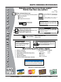
PARTS ORDERING PROCEDURES
Ordering parts has never been easier!
Choose from three easy options:
Order via Internet (Dealers Only):
Best Deal!
Effective:
January 1st, 2006
If you have an MQ Account, to obtain a Username
and Password, E-mail us at: parts@multiquip.
com.
Order parts on-line using Multiquip’s SmartEquip website!
■ View Parts Diagrams
■ Order Parts
■ Print Specification Information
To obtain an MQ Account, contact your
District Sales Manager for more information.
Use the internet and qualify for a 5% Discount
on Standard orders for all orders which include
complete part numbers.*
Goto www.multiquip.com and click on
Order Parts to log in and save!
Note: Discounts Are Subject To Change
Order via Fax (Dealers Only):
All customers are welcome to order parts via Fax.
Domestic (US) Customers dial:
1-800-6-PARTS-7 (800-672-7877)
Fax your order in and qualify for a 2% Discount
on Standard orders for all orders which include
complete part numbers.*
Note: Discounts Are Subject To Change
Order via Phone: Domestic (US) Dealers Call:
1-800-427-1244
Non-Dealer Customers:
Contact your local Multiquip Dealer for
parts or call 800-427-1244 for help in
locating a dealer near you.
International Customers should contact
their local Multiquip Representatives for
Parts Ordering information.
When ordering parts, please supply:
❒
❒
❒
❒
❒
❒
Dealer Account Number
Dealer Name and Address
Shipping Address (if different than billing address)
Return Fax Number
Applicable Model Number
Quantity, Part Number and Description of Each Part
❒
Specify Preferred Method of Shipment:
✓ UPS/Fed Ex
✓ DHL
■ Priority One
✓ Truck
■ Ground
■ Next Day
■ Second/Third Day
NOTICE
All orders are treated as Standard Orders and will
ship the same day if received prior to 3PM PST.
WE ACCEPT ALL MAJOR CREDIT CARDS!
MTX80/90 RAMMER — OPERATION AND PARTS MANUAL — REV. #9 (1/14/11) — PAGE 5
SAFETY INFORMATION
Do not operate or service the equipment before reading
the entire manual. Safety precautions should be followed
at all times when operating this equipment.
Failure to read and understand the safety
messages and operating instructions could
result in injury to yourself and others.
Potential hazards associated with the operation of this
equipment will be referenced with hazard symbols which
may appear throughout this manual in conjunction with
safety messages.
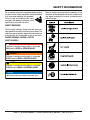
SAFETY MESSAGES
The four safety messages shown below will inform you
about potential hazards that could injure you or others. The
safety messages specifically address the level of exposure
to the operator and are preceded by one of four words:
DANGER, WARNING, CAUTION or NOTICE.
SAFETY SYMBOLS
DANGER
Indicates a hazardous situation which, if not avoided,
WILL result in DEATH or SERIOUS INJURY.
WARNING
Indicates a hazardous situation which, if not avoided,
COULD result in DEATH or SERIOUS INJURY.
CAUTION
Indicates a hazardous situation which, if not avoided,
COULD result in MINOR or MODERATE INJURY.
NOTICE
Addresses practices not related to personal injury.
PAGE 6 — MTX80/90 RAMMER — OPERATION AND PARTS MANUAL — REV. #9 (1/14/11)
SAFETY INFORMATION
GENERAL SAFETY
CAUTION
NEVER operate this equipment without proper protective
clothing, shatterproof glasses, respiratory protection,
hearing protection, steel-toed boots and other protective
devices required by the job or city and state regulations.
ALWAYS know the location of the nearest phone or keep a
phone on the job site. Also, know the phone numbers of
the nearest ambulance, doctor and fire department. This
information will be invaluable in the case of an emergency.
RAMMER SAFETY
DANGER
NEVER operate this equipment when not
feeling well due to fatigue, illness or when
under medication.
NEVER operate this equipment under the influence of
drugs or alcohol.
ALWAYS check the equipment for loosened threads or
bolts before starting.
DO NOT use the equipment for any purpose other than
its intended purposes or applications.
NOTICE
This equipment should only be operated by trained and
qualified personnel 18 years of age and older.
Whenever necessary, replace nameplate, operation and
safety decals when they become difficult read.
Manufacturer does not assume responsibility for any
accident due to equipment modifications. Unauthorized
equipment modification will void all warranties.
NEVER use accessories or attachments that are not
recommended by Multiquip for this equipment. Damage
to the equipment and/or injury to user may result.
ALWAYS know the location of the nearest
fire extinguisher.
ALWAYS know the location of the nearest
first aid kit.
NEVER operate the equipment in an explosive
atmosphere or near combustible materials. An
explosion or fire could result causing severe
bodily harm or even death.
WARNING
NEVER disconnect any emergency or safety devices.
These devices are intended for operator safety.
Disconnection of these devices can cause severe injury,
bodily harm or even death. Disconnection of any of these
devices will void all warranties.
DO NOT use this machine on ground that is harder than
the machine can handle, or for driving pilings or tamping
rock beds. Furthermore, use of the machine on sloping
ground, such as the side of an embankment, may make
the machine unstable and can cause an accident. It can
also result in premature machine wear due to uneven
loads on the machine.
Use the machine with confidence for tamping earth and
sand, soil, gravel, and asphalt. DO NOT use the machine
for other types of jobs.
CAUTION
NEVER lubricate components or attempt service on a
running machine.
NOTICE
ALWAYS keep the machine in proper running condition.
Fix damage to machine and replace any broken parts
immediately.
ALWAYS store equipment properly when it is not being
used. Equipment should be stored in a clean, dry location
out of the reach of children and unauthorized personnel.
MTX80/90 RAMMER — OPERATION AND PARTS MANUAL — REV. #9 (1/14/11) — PAGE 7
SAFETY INFORMATION
ENGINE SAFETY
DANGER
The engine fuel exhaust gases contain poisonous carbon
monoxide. This gas is colorless and odorless, and can
cause death if inhaled.
FUEL SAFETY
DANGER
DO NOT add fuel to equipment if it is placed inside truck
bed with plastic liner. Possibility exists of explosion or
fire due to static electricity.
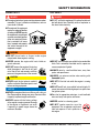
The engine of this equipment
requires an adequate free flow
of cooling air. NEVER operate
this equipment in any enclosed
or narrow area where free flow
of the air is restricted. If the air
flow is restricted it will cause
injury to people and property
and serious damage to the
equipment or engine.
WARNING
DO NOT place hands or fingers inside engine
compartment when engine is running.
NEVER operate the engine with heat shields or
guards removed.
DO NOT remove the engine oil drain plug
while the engine is hot. Hot oil will gush
out of the oil tank and severely scald any
persons in the general area of the rammer.
CAUTION
NEVER touch the hot exhaust manifold,
muffler or cylinder. Allow these parts to cool
before servicing equipment.
NOTICE
NEVER run engine without an air filter or with a dirty air
filter. Severe engine damage may occur. Service air filter
frequently to prevent engine malfunction.
NEVER tamper with the factory settings
of the engine or engine governor. Damage
to the engine or equipment can result
if operating in speed ranges above the
maximum allowable.
DO NOT start the engine near spilled fuel or combustible
fluids. Fuel is extremely flammable and its vapors can
cause an explosion if ignited.
ALWAYS refuel in a well-ventilated area, away from
sparks and open flames.
ALWAYS use extreme caution when working with
flammable liquids.
DO NOT fill the fuel tank while the engine is running
or hot.
DO NOT overfill tank, since spilled fuel could ignite if it
comes into contact with hot engine parts or sparks from
the ignition system.
Store fuel in appropriate containers, in well-ventilated
areas and away from sparks and flames.
NEVER use fuel as a cleaning agent.
DO NOT smoke around or near the
equipment. Fire or explosion could result
from fuel vapors or if fuel is spilled on a
hot engine.
PAGE 8 — MTX80/90 RAMMER — OPERATION AND PARTS MANUAL — REV. #9 (1/14/11)
SAFETY INFORMATION
TRANSPORTING SAFETY
CAUTION
NEVER allow any person or animal to stand underneath
the equipment while lifting.
NOTICE
Before lifting, make sure that the equipment parts (hook
and vibration insulator) are not damaged and screws are
not loose or missing.
Always make sure crane or lifting device has been
properly secured to the lifting bail (hook) of the
equipment.
ALWAYS shutdown engine before transporting.
NEVER lift the equipment while the engine is running.
Tighten fuel tank cap securely and close fuel cock to
prevent fuel from spilling.
Use adequate lifting cable (wire or rope) of sufficient
strength.
Use one point suspension hook and lift straight
upwards.
DO NOT lift machine to unnecessary heights.
ALWAYS tie down equipment during transport by
securing the equipment with rope.
Never allow any person or animal to stand underneath the
equipment while lifting.
ENVIRONMENTAL SAFETY
NOTICE
Dispose of hazardous waste properly.
Examples of potentially hazardous waste
are used motor oil, fuel and fuel filters.
DO NOT use food or plastic containers to dispose of
hazardous waste.
DO NOT pour waste, oil or fuel directly onto the ground,
down a drain or into any water source.
MTX80/90 RAMMER — OPERATION AND PARTS MANUAL — REV. #9 (1/14/11) — PAGE 9
GENERAL INFORMATION
Definition of Tamping Rammer
The Mikasa MTX80/MTX90 tamping rammer is a powerful
compacting tool capable of applying a tremendous force in
consecutive impacts to a soil surface. Its applications include
soil compacting for road, embankments and reservoirs as
well as backfilling for gas pipelines, water pipelines and cable
installation work.
The impact force of the MTX80/MTX90 levels and uniformly
compacts voids between soil particles to increase dry density.
Circular motion is converted to create impact force. The
MTX80/MTX90 tamping rammer develops a powerful
compacting force at the foot of the rammer. To maintain
optimum performance, proper operation and service are
essential.
Construction of Tamping Rammer
The Mikasa MTX80/MTX90 is equipped with an air cooled,
four- cycle gasoline engine. Transmission of the power takes
place by increasing the engine speed to engage the
centrifugal clutch.
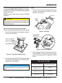
Rammer Gearbox and Spring Cylinder
The Mikasa MTX80/MTX90 uses an oil bath lubrication
system. Always check the oil level through the oil level sight
glass at the rear of the tamper foot.
Handle Operation
CAUTION
Before starting operation check the lifting
handle to:
1. Make sure that there is no damage on the bolts.
2. Make sure that there is no crack or breakage on handle.
3. Make sure that there is no fissure on the surface. If there
is any abnormality or damage, replace with new one.
For operation:
This handle is to be used to lift up the shoe part of the machine
with the body laid down on the ground or truck bed.
1. Use proper lifting techniques to avoid back injury. This
handle is for manual lifting only.
2. Do not use this handle as a rammer lift point. Use the
lifting point on the top of the machine.
3. Do not move the rammer with the lifting handle and the
front rollers more than 16 feet (5 meters).
Controls
Before starting the MTX80/MTX90 Tamping Rammer identify
and understand the function of the controls.
PAGE 10 — MTX80/90 RAMMER — OPERATION AND PARTS MANUAL — REV. #9 (1/14/11)
SPECIFICATIONS
Table 1. MTX80/MTX90 Rammer Specifications
Model
MTX-80
MTX-90
Overall Height
39.37 in. (1000 mm)
39.37 in. (1000 mm)
Overall Width
14.37 in (365 mm)
14.37 in (365 mm)
Over Length
31.02 in (788 mm)
31.02 in (788 mm)
Shoe Size
13.4 x 11.2 in (340 x 285 mm)
13.4 x 11.2 in (340 x 285 mm)
Fuel Tank Capacity
3.2 qt. (3 liters)
3.2 qt. (3 liters)
Lubrication Oil Capacity
0.8 quart (0.75 liter)
0.8 quart (0.75 liter)
No. of Impacts Per Second
10.6 - 11.3
11.0 - 11.6
Impact Force
3,080 lb (13.7 kN)
3,530 lb (15.7 kN)
Impact Plate Stroke
2 - 3.15 in (50 - 80 mm)
2 - 3.15 in (50 - 80 mm)
Operating Weight
183 lbs. (83 kg)
196 lbs. (89 kg)
Speed Setting
3400-3600 rpm
3500-3700 rpm
Measured Sound Power Level
105 dB
105 dB
Guaranteed Sound Power
Level
107 dB
107 dB
Max. Sound Pressure Level
95 dB
97 dB
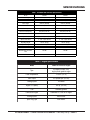
Table 2. Engine Specifications
Model
Robin EH122D46530 Engine
Type
Air-Cooled 4 Stroke, OHV,
single cylinder gasoline engine
Piston Displacement
7.4 cu.in. (121 cc)
Max. Output
3.5 hp/3,600 rpm (2.6 KW)
Cooling System
Air-Cooled
Engine Oil Capacity
0.42 qt. (0.4 liter)
Fu e l
Unleaded gasoline
Lubricant for Engine
Automobile Oil; Class SE or higher
Starting System
Recoil Starter
Spark Plug Type
NGK BR6ES
MTX80/90 RAMMER — OPERATION AND PARTS MANUAL — REV. #9 (1/14/11) — PAGE 11
COMPONENTS
3
10
2
4
1
5
9
6
11
7
12
13
8
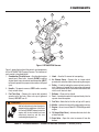
Figure 1. MTX80/MTX90 Rammer
Figure 1 shows the location of the controls and components
for the MTX80/MTX90 Tamping Rammer. The functions of
each control is described below:
1. Combination (Throttle) Lever – Used to adjust engine
speed (rpm). Move lever forward (SLOW) to reduce
engine speed, move lever back toward operator (FAST)
to increase speed. Always operate the rammer at full speed
(rpm).
2. Handle – To operate rammer, GRIP handle assembly
firmly on both sides.
3. Fuel Tank Cap – Remove this cap to add unleaded
gasoline to the fuel tank. Make sure cap is tightened
securely. DO NOT over fill.
WARNING
Add fuel to the tank only when the engine is
stopped and has cooled down. In the event
of a fuel spill, DO NOT attempt to start the
engine until the fuel residue has been
completely wiped up and the area
surrounding the engine is dry.
4. Hook – Used to lift rammer for transporting.
5. Air Cleaner Cover – Protects the air cleaner which
prevents dirt and other debris from entering the engine.
6. Roller – Used for loading the rammer in back end of a
truck. Rammer is brought to tail gate roller side toward
the truck bed and driver lifts roller with handle at base and
rolls the unit into truck bed.
7. Bellows – Reservoir for oil bath.
8. Foot – Laminated wood with tempered steel plate for
superior shock absorption.
9. Fuel Tank – Holds the fuel for the unit (up to 3.2 quarts)
10. Muffler – reduces the noise of the engine when running.
11. Engine – this unit uses a Robin EH122D46530 gasoline
engine.
12. Oil Gauge (Sight Glass) – Indicates the level of oil in the
oil bath reservoir.
13. Drain Valve – Open this valve to remove oil from the
bellows.
PAGE 12 — MTX80/90 RAMMER — OPERATION AND PARTS MANUAL — REV. #9 (1/14/11)
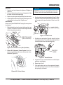
BASIC ENGINE
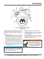
Figure 2. Engine Controls and Components
(Robin EH-12-2D)
The engine (Figure 2) must be checked for proper lubrication
and filled with fuel prior to operation. Refer to the manufacturer's
Engine manual for instructions & details of operation and
servicing.
1. Secondary Air Cleaner – Prevents dirt and other debris
from entering the fuel system. Remove wing-nut on top
of air filter cannister to gain access to filter element.
2. Choke Lever – Used when starting the engine. Normally
used in cold weather conditions. In cold weather turn
the choke lever to the fully closed position, in warm
weather set choke lever half way or completely open.
3. Spark Plug – Provides spark to the ignition system.
Set spark plug gap to 0.024 - 0.028 inch (0.6 - 0.7 mm).
Clean spark plug once a week.
4.
5.
6.
Muffler – Used to reduce noise and emissions.
Recoil Starter (pull rope) – Manual-starting method.
Pull the starter grip until resistance is felt, then pull
briskly and smoothly.
Engine ON/OFF Switch – Controls the starting and
stopping of the engine. Switch must be in the "ON"
position when starting the engine.
WARNING
Engine components can generate extreme
heat.To prevent burns, DO NOT touch these
areas while the engine is running or
immediately after operating. NEVER operate
the engine with the muffler removed.
NOTICE
Operating the engine without an air filter, with a damaged air
filter, or a filter in need of replacement will allow dirt to enter
the engine, causing rapid engine wear.
MTX80/90 RAMMER — OPERATION AND PARTS MANUAL — REV. #9 (1/14/11) — PAGE 13
OPERATION
This section is intended to assist the operator with the initial
start-up of the MTX80/MTX90 Tamping Rammer. It extremely
important that this section be read carefully before attempting
to operate the rammer.
DO NOT use your rammer until this section is thoroughly
understood.
CAUTION
Failure to understand the operation of the MTX80/MTX90
Tamping Rammer could result in severe damage to the
unit or personal injury.
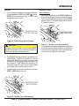
Engine
1. Fill the fuel tank (Figure 4) with unleaded gasoline. At the
same time, check the engine oil and make it a habit to
replenish it often (Figure 5).
FUEL
TANK
Rammer Crankcase and Spring Cylinder Oil Bath
This unit uses an oil bath lubrication system. Perform the following:
Figure 4. Fuel Tank
1. Check the oil level through the oil level sight glass (Figure 3)
at the rear of the tamper foot.
OIL LEVEL
DIPSTICK
OIL FILL PLUG
SIGHT GLASS
OIL DRAIN PLUG
Figure 5. Engine Oil Dipstick
Figure 3. Foot Housing Sight Glass
2. If oil is not visible, add 10W-30 SE, SF or higher grade motor
oil into the oil fill plug opening (Figure 3). The bath contains
approximately 1.7 pints (800 cc.)
NOTICE
The oil level should be kept at the half way point of the sight
glass.
2. Check the engine oil level and if the engine oil level is low,
it should be refilled. Low levels of oil may result in engine
seizure. Use the proper motor oil as suggested in the Table
3 below.
Table 3 Motor Oil Grade
Season or Temperature
Grade of motor oil
(higher than MS class)
Spring, Summer or Autumn
+120° F to +15° F
SAE 30
Winter
+40° F to +15° F
SAE 30
Below +15° F
SAE 10W-30
PAGE 14 — MTX80/90 RAMMER — OPERATION AND PARTS MANUAL — REV. #9 (1/14/11)
OPERATION
Inspection
NOTICE
1 . Check all nuts, bolts fasteners for tightness. Retighten as
necessary.
DO NOT press the primer pump bulb more than four
(4) times, as this will cause fuel to flood the carburetor.
2. Clean any dirt from the recoil starter and foot pedestal. Wipe
the entire unit clean before operating.
3. Replace any missing or damaged Safety Operation decals.
4. Adjust height of handle. Adjust handle by loosening nuts and
moving handle to suit operation. Retighten nuts.
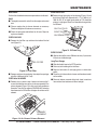
Initial Start-up
3.
Place the choke lever to the closed position (Figure 7).When
the weather is cold, close the choke all the way.When it is hot,
or if the engine is hot, open the choke a little or leave it fully
open.
When starting the MTX80/MTX90 Tamping Rammer perform
the following:
1.
CHOKE LEVER
(CLOSED POSITION)
Slide the throttle lever from the stop to the idle position ( )
(Figure 6).This opens the fuel cock and the engine electrical
circuit is turned on automatically.
THROTTLE LEVER
(IDLE POSITION)
Figure 7. Choke Lever
4. Grip the starter rope handle (Figure 8) and pull it until you
feel a slight resistance.Then pull sharply and quickly. Return
the handle to the starter case before releasing.
Figure 6-A. Throttle Lever (Idle {Position)
STARTER
ROPE
2. Units with Carburetor Primer System: Push the
primer pump bulb four (4) times to deliver fuel to the
carburetor (Figure 5-B).
Figure 8. Recoil Starter
5. If engine fails to start, move the choke lever to the half open
position to avoid flooding.
6. Repeat steps 1 thru 5.
7. If the engine does not start after repeated attempts,
check the spark plug for excess fuel. Clean and replace
the spark plug as needed.
Figure 6-B. Primer Pump
MTX80/90 RAMMER — OPERATION AND PARTS MANUAL — REV. #9 (1/14/11) — PAGE 15
OPERATION
Operation
Stopping The Engine
1. To start the rammer tamping action, move the throttle lever
(Figure 9) quickly from IDLE to the START ( ) position.
DO NOT move the throttle lever slowly as this may cause
damage to the clutch or spring.
Normal Shutdown
1. Move throttle lever quickly from the START to IDLE position
(Figure 10) and run the engine for three minutes at low speed.
After the engine cools, move the throttle lever to the STOP
position (Figure 11). The engine will stop and the fuel cock
is automatically closed.
THROTTLE LEVER
(START POSITION)
THROTTLE LEVER
(STOP POSITION)
Figure 9. Throttle Lever (Start Position)
Figure 11. Throttle Lever (Stop Position)
CAUTION
Make sure that the throttle lever is moved to the FULL START
position. Operating the rammer at less than full speeds can
result in damage to the clutch springs or foot.
2. If the engine does not stop due to a problem with the switch
or the like, move the machine to a safe location and hold the
throttle lever in the stop position. Let the machine run on idle
and the machine will stop after a few minutes.
2. The MTX80/MTX90 tamping rammer is designed to run at
3,600/3700 rpm. At optimum rpm the foot hits at the rate
between 590 ~ 695 impacts per minute. Increasing throttle
speed past factory set rpm does not increase impacts and
may damage unit. The MTX80/MTX90 is designed to advance while tamping. For faster advance, pull back slightly
on the handle so that rear of foot contacts soil first.
3. To stop the tamping action, move throttle lever quickly from
START to IDLE position (Figure 10).
THROTTLE LEVER
(IDLE POSITION)
Figure 10. Throttle Lever (Idle Position)
PAGE 16 — MTX80/90 RAMMER — OPERATION AND PARTS MANUAL — REV. #9 (1/14/11)
MAINTENANCE
Maintenance
Perform the scheduled maintenance procedures as indicated:
DAILY
■ Thoroughly remove dirt and oil from the engine and control
area.
■ Clean or replace the air cleaner elements as necessary.
Check and retighten all fasteners as necessary.
■ Check the spring box and bellows for oil leaks. Repair or
replace as needed.
EVERY 200 HOURS
■ Remove the oil drain plug on foot housing (Figure 14) and
drain the oil. Refill with approximately 1.7 pt. (800 cc.) of
10W-30 SE, SF or higher grade motor oil. Oil should be
midway in sight glass. Break in oil should be changed after
first 50 hours.
OIL FILL PLUG
SIGHT GLASS
OIL DRAIN PLUG
EVERY 50 HOURS
■ Remove the fuel filter cap and clean the inside of the fuel
tank (Figure 12).
Figure 14. Oil Drain Plug
EVERY 2YEARS
■ Replace the fuel line every 250 hours or every 2 years even
if there is no visible damage.
FUEL FILTER
Long Term Storage
■ Slide the throttle lever to the STOP position.
■ Drain any fuel including in the fuel hose.
■ Replace lubrication oil and apply grease to lubrication
points.
Figure 12. Fuel Filter
■ Remove and clean the spark plug, then adjust the spark gap
to 0.024~0.028 inch (0.6~0.7 mm).
■ Cover the air intake on the air cleaner and the exhaust outlet
on the muffler.
EVERY 80 to 100 HOURS
■ Remove the air cleaner cover. Loosen and remove the 2
screws that hold the cover to the air cleaner assembly. If the
primary element (Figure 13) is dirty, wash it with gasoline or
kerosene. Then dip it in engine oil (SAE10W-30) and wring
the element so that 25 to 30 cc of engine oil remains on the
element.
■ Store unit indoors covered with plastic sheet in moisture
free and dust free location out of direct sunlight.
PRIMARY
ELEMENT
Figure 13. Air Cleaner Primary Element
MTX80/90 RAMMER — OPERATION AND PARTS MANUAL — REV. #9 (1/14/11) — PAGE 17
TROUBLESHOOTING
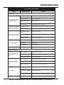
TABLE 4. ENGINE TROUBLESHOOTING
SYMPTOM
POSSIBLE PROBLEM
SOLUTION
Difficult to start
Fuel is available but spark plug
will not ignite. (Power available
at high tension cable).
Fuel is available but spark plug
will not ignite. (Power NOT
available at high tension cable).
Fuel is available and spark plug
ignites (compression normal).
Fuel is available and spark plug
ignites (compressionlow).
Low compression.
Ignition plug being bridge?
Check ignition system.
Carbon deposit at ignition?
Clean or replace ignition.
Short circuit due to defective
insulators?
Replace insulators.
Improper spark gap?
Set spark plug gap to the correct gap.
Short circuit at stop switch?
Check stop switch circuit. Replace stop switch if defective.
Ignition coil defective?
Replace ignition coil.
Muffler clogged with carbon
deposits?
Clean or replace muffler.
Fuel in use inadequate (water,
dust)?
Flush fuel sytem and replace with fresh fuel.
Air Cleaner clogged?
Clean or replace air cleaner.
Defective cylinder head gasket?
Tighten cylinder head bolts or replace head gasket.
Cylinder worn?
Replace cylinder.
Spark plug loose?
Tighen spark plug.
Incorrect valve adjustment?
Check and adjust valves.
Air cleaner clogged?
Clean or replace air cleaner.
Air in fuel line?
Bleed (remove air) from fuel line.
Carbon deposits in cylinder?
Clean or replace cylinder
Ignition coil defective?
Flush fuel sytem and replace with fresh fuel.
Ignition plug often shorts?
Replace ignition wires, clean ignition.
Fuel in use inadequate (water,
dust)?
Flush fuel sytem and replace with fresh fuel.
Excessive carbon depostion in
combustion chamber?
Clean or replace crankcase.
Exhaust or muffler clogged with
carbon.
Clean or replace muffler.
Operation not satisfactory
Not enough power available
(compression normal, no missfiring).
Not enough power available
(compression normal, missfiring).
Engine overheats.
Spark plug heat value incorrect? Replace spark plug with correct type spark plug.
Engine high speed incorrect.
Incorrect engine RPM?
Check and adjust engine RPM to 3400-3600 RPM.
PAGE 18 — MTX80/90 RAMMER — OPERATION AND PARTS MANUAL — REV. #9 (1/14/11)
TROUBLESHOOTING
ENGINE
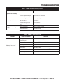
TABLE 4. ENGINE TROUBLESHOOTING (continued)
SYMPTOM
POSSIBLE PROBLEM
SOLUTION
Operation not satisfactory
Rotational speed fluctuates.
Recoil star ter not working
properly.
Governor adjustment improper?
Adjust governor to correct lever.
Governor spring defective?
Clean or replace ignition.
Fuel flow erratic?
Check fuel line.
Air taken in through suction
line?
Check suction line.
Dust in rotating par t?
Clean recoil star ter assembly.
Spring spring failure?
Replace sprial spring.
TABLE 5. RAMMER TROUBLESHOOTING
SYMPTOM
Engine runs but rammer jumps
erratically or not at all..
POSSIBLE PROBLEM
SOLUTION
Operating speed of throttle lever
is incorrectly set?
Set throttle lever to correct position.
Oil in excess?
Drain excess oil. Bring to correct level.
Clutch slips?
Replace or adjust clutch.
Spring Failure?
Replace sprial spring.
Speed of engine improper?
Adjust engine speed to correct operating RPM setting.
Soil over-compacted?
Shut-down machine and test soil.
MTX80/90 RAMMER — OPERATION AND PARTS MANUAL — REV. #9 (1/14/11) — PAGE 19
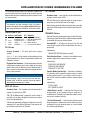
EXPLANATION OF CODES IN REMARKS COLUMN
The following section explains the different symbols and
remarks used in the Parts section of this manual. Use the
help numbers found on the back page of the manual if there
are any questions.
NOTICE
The contents and part numbers listed in the parts
section are subject to change without notice. Multiquip
does not guarantee the availability of the parts listed.
SAMPLE PARTS LIST
NO.
1
2%
2%
3
4
PART NO. PART NAME
QTY. REMARKS
12345
BOLT......................1 .....INCLUDES ITEMS W/%
WASHER, 1/4 IN............NOT SOLD SEPARATELY
12347
WASHER, 3/8 IN....1 .....MQ-45T ONLY
12348
HOSE ..................A/R ...MAKE LOCALLY
12349
BEARING ..............1 .....S/N 2345B AND ABOVE
NO. Column
QTY. Column
Numbers Used — Item quantity can be indicated by a
number, a blank entry, or A/R.
A/R (As Required) is generally used for hoses or other
parts that are sold in bulk and cut to length.
A blank entry generally indicates that the item is not sold
separately. Other entries will be clarified in the “Remarks”
Column.
REMARKS Column
Some of the most common notes found in the “Remarks”
Column are listed below. Other additional notes needed
to describe the item can also be shown.
Assembly/Kit — All items on the parts list with the
same unique symbol will be included when this item is
purchased.
Unique Symbols — All items with same unique
symbol
Indicated by:
“INCLUDES ITEMS W/(unique symbol)”
(@, #, +, %, or >) in the number column belong to the
same assembly or kit, which is indicated by a note in the
“Remarks” column.
Serial Number Break — Used to list an effective serial
number range where a particular part is used.
Duplicate Item Numbers — Duplicate numbers indicate
multiple part numbers, which are in effect for the same
general item, such as different size saw blade guards in
use or a part that has been updated on newer versions
of the same machine.
NOTICE
When ordering a part that has more than one item
number listed, check the remarks column for help in
determining the proper part to order.
PART NO. Column
Numbers Used — Part numbers can be indicated by a
number, a blank entry, or TBD.
TBD (To Be Determined) is generally used to show a
part that has not been assigned a formal part number
at the time of publication.
A blank entry generally indicates that the item is not sold
separately or is not sold by Multiquip. Other entries will
be clarified in the “Remarks” Column.
Indicated by:
“S/N XXXXX AND BELOW”
“S/N XXXX AND ABOVE”
“S/N XXXX TO S/N XXX”
Specific Model Number Use — Indicates that the part
is used only with the specific model number or model
number variant listed. It can also be used to show a
part is NOT used on a specific model or model number
variant.
Indicated by:
“XXXXX ONLY”
“NOT USED ON XXXX”
“Make/Obtain Locally” — Indicates that the part can
be purchased at any hardware shop or made out of
available items. Examples include battery cables, shims,
and certain washers and nuts.
“Not Sold Separately” — Indicates that an item cannot
be purchased as a separate item and is either part of an
assembly/kit that can be purchased, or is not available
for sale through Multiquip.
PAGE 20 — MTX80/90 RAMMER — OPERATION AND PARTS MANUAL — REV. #9 (1/14/11)
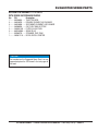
SUGGESTED SPARE PARTS
MTX80/MTX90 RAMMER 1 TO 3 UNITS
WITH ROBIN EH122D46530 ENGINE
Qty.
P/N
Description
1 ......... 956100063 ....... THROTTLE WIRE
3 ......... 366010070 ....... PRIMARY ELEMENT, AIR CLEANER
3 ......... 366010080 ....... SECONDARY ELEMENT, AIR CLEANER
1 ......... 366900020 ....... CAP, FUEL TANK W/ STRAP
2 ......... 26365012A3 .... FILTER, IN-LINE FUEL
3 ......... 0650140580 ..... SPARK PLUG
1 ......... 959300770 ....... STRAINER, FUEL TANK
1 ......... 2825011118 ..... ROPE, RECOIL STARTER
NOTICE
Part numbers on this Suggested Spare Parts List may
supersede/replace the P/N shown in the text pages of
this book.
MTX80/90 RAMMER — OPERATION AND PARTS MANUAL — REV. #9 (1/14/11) — PAGE 21
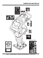
NAMEPLATE AND DECALS
1
4
7
NPA-0000
?
?
?
?
?
?
?
NPA-1245
2
3
5
STOP
NPA-0000
NPA-0000
6
11
MODEL
SERIAL NO.
A (DECAL SET)
8
MTX
series
RAMMER
quick manual
Engine Oil
Use SAE 10W/30,SE or higher grade motor oil
RAMMING CYLINDER OIL
Use SAE 10W/30,SF or higher grade moter oil
Fuel
Use normal quality gasoline
PAGE 22 — MTX80/90 RAMMER — OPERATION AND PARTS MANUAL — REV. #9 (1/14/11)
NAMEPLATE AND DECALS
NO
A
1#
2#
3#
4#
5#
6#
7#
8
11
PART NO
920900040
920212540
PART NAME
QTY.
REMARKS
DECAL SET ..................................... 1 .......... INCLUDES ITEMS W/ #
DECAL: OPERATION
1
DECAL: AIR CLEANER
1
DECAL: LEVER OPERATION
1
DECAL: MAX SPEED
1
DECAL: MACHINE STOP
1
DECAL: EC NOISE REQ
1
DECAL: ANTI-VIB HANDLE
1
QUICK MANUAL
1
DECAL: NAMEPLATE ...................... 1 .......... CONTACT MQ PARTS DEPT W/ SERIAL NO.
MTX80/90 RAMMER — OPERATION AND PARTS MANUAL — REV. #9 (1/14/11) — PAGE 23
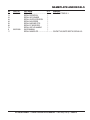
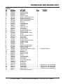
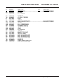
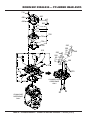
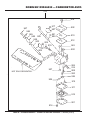
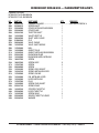
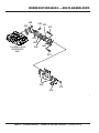
CRANKCASE AND ENGINE ASSY.
46
43
47
44
44 47
35-4
35-3
35-2
75-1
75-2
75-3
35-1
35
35-7
70
74
73
35-9
35-8
39
40-1
40-2
40-3
35-5
55-1
55-2
31-1
31-2
48
52
53
38
41-2
NEW
STYLE
CLUTCH
41-1
49
54
34
33
77
49
55-2
55-1
32
30
48
24-1
27
45
22
22
23
24-2
68
67
25
4
51
28-2
28-1
11
9
10
14
12
19
20
59
53
54
A
101
6
106
1
16
815
7
3
65
63
65 64
63
64
61
58
26
57
60
56
A
13
82
79
37
37 36
59
111
80
78
56
62
66
55-2
55-1
5
18
81
PAGE 24 — MTX80/90 RAMMER — OPERATION AND PARTS MANUAL — REV. #9 (1/14/11)
OLD
STYLE
CLUTCH
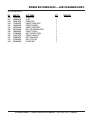
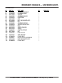
CRANKCASE AND ENGINE ASSY.
NO.
1
3
4
5
6
7
8
9
10
11
12
13
14
15
16
18
19
20
22
PART NO.
366118940
041006007
367345180
060404010
080200350
080100620
040006207
040006305
080100720
080200350
080200250
366345230
040006304
080100520
080200200
047940060
050710080
001520825
366346210
22
366348550
23
24-1
24-2
25
26
27
28-1
28-2
30
31-1
31-2
32
33
34
35
35-1#
35-2#
35-3#
35-4#
35-5#
35-7#
35-8#
35-9#
36
37
38
39
952401450
001220825
030208200
367217260
001710830
022611010
001221054
030210250
366346280
001211030
030210250
939010270
030208200
020308060
366900010
366010010
366010020
366010030
366010040
366010050
366010070
366010080
362030040
367217460
954407682
366460160
366460150
PART NAME
QTY.
REMARKS
CRANK CASE
1
BEARING 6007Z
1
PINION, DRUM
1
OIL SEAL TC-40528
1
STOP RING S-35
1
STOP RING R-62
1
BEARING 6207
1
BEARING 6305
1
STOP RING R-72
1
STOP RING S-35
1
STOP RING S-25
1
CONNECTING ROD
1
BEARING 6304
1
STOP RING R-52
1
STOP RING S-20
1
NEEDLE BEARING FJ-1816
1
O-RING AS568-267
1
SOCKET HEAD BOLT 8X25 T
8
CLUTCH ASSY ....................................... 1 ......... MTX80: S/N S-3939 AND BELOW
............................................................................. MTX90: S/N S-1298 AND BELOW
CLUTCH ASSY ....................................... 1 ......... MTX80: S/N S-3940 AND ABOVE
............................................................................. MTX90: S/N S-1299 AND ABOVE
WASHER 8.5X22X3
1
BOLT 8X25 T
1
WASHER, LOCK M8
1
FLANGE, ENGINE
1
FLANGE BOLT 8X30
4
FLANGE NUT M10 H
2
BOLT 10X70 T
2
WASHER, LOCK M10
2
BRACKET, SHOCK ABSORBER
1
BOLT 10X30 H
4
WASHER, LOCK M10
4
STOPPER RUBBER ( 70 )
1
WASHER, LOCK M8
1
NUT M8
1
AIR CLEANER ASSY ............................... 1 ......... INCLUDES ITEMS W/ #
AIR CLEANER COVER
1
WASHER, FLAT M6
2
WASHER, LOCK M6
2
COIN BOLT M6
2
BASE CP, AIR CLEANER
1
PRIMARY ELEMENT CP
1
SECONDARY ELEMENT
1
GRIP BOLT CP, AIR CLEANER
1
PIPE, INTAKE
1
CYCLONE CLAMP (CY-1) 38
2
SEALING FORM, UNDER
1
SEALING FORM, SIDE
1
MTX80/90 RAMMER — OPERATION AND PARTS MANUAL — REV. #9 (1/14/11) — PAGE 25
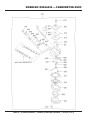
CRANKCASE AND ENGINE ASSY.
46
43
47
44
44 47
35-4
35-3
35-2
75-1
75-2
75-3
35-1
35
35-7
70
74
73
35-9
35-8
39
40-1
40-2
40-3
35-5
55-1
55-2
31-1
31-2
48
52
53
38
41-2
NEW
STYLE
CLUTCH
41-1
49
54
34
33
77
49
55-2
55-1
32
30
48
22
22
23
24-2
24-1
68
67
27
45
25
4
51
28-2
28-1
11
9
10
14
12
19
20
59
53
54
A
101
6
106
1
16
815
7
3
65
63
65 64
63
64
61
58
26
57
60
56
A
13
82
79
37
37 36
59
111
80
78
56
62
66
55-2
55-1
5
18
81
PAGE 26 — MTX80/90 RAMMER — OPERATION AND PARTS MANUAL — REV. #9 (1/14/11)
OLD
STYLE
CLUTCH
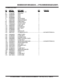
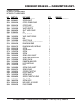
CRANKCASE AND ENGINE ASSY.
CONTINUED
NO.
PART NO.
40-1
001220851
40-2
030208200
40-3
031108160
41-1
001210815
41-2
030208200
43
366217340
44
366460140
45
366217350
46
366345980
47
050200060
48
009110040
49
959407670
51
367118990
52
367119000
53
022910260
54
366460170
55-1
001520820
55-2
031108160
56
009110038
57
367217490
58
009110039
59
022910250
60
367119010
61
367346290
62
009110042
63
030208200
64
031108160
65
020308060
66
009110043
67
001520820
68
030208200
70
366900042
74@
956100063
75-1
001220620
75-2
030206150
75-3
031106100
76
020306050
77
959006120
78
367460120
79
2067550101
80
959021810
81
454010020
82
954010280
101
367345200
106
366010120
106
366010121
106
366010130
106
366010131
111
911211217
PART NAME
QTY.
REMARKS
BOLT 8X55 T
2
WASHER, LOCK M8
2
WASHER, FLAT M8
2
BOLT 8X15 H
2
WASHER, LOCK M8
2
COVER, CLEANER ASSY (UPPER)
1
RUBBER BUSH (10X16X17)
2
COVER, CLEANER ASSY (UNDER)
1
KNOB, CLEANER COVER
2
O-RING P6
2
FLANGE BOLT 8X20
4
SQUARE NUT M8
4
GUARD, LINK
1
GUARD, MUFFLER
1
WELL NUT M8
2
FLANGE COLLAR 8
2
SOCKET HEAD BOLT 8X20 T
4
WASHER, FLAT M8
4
SOCKET HEAD BOLT 8X30 ZN
2
EX BAR
1
SOCKET HEAD BOLT 6X25 ZN
4
WELL NUT M6
4
GUARD, ENGINE
1
SUPPORT, ENGINE
1
S.H.BOLT8X45 WHOLE THREAD
2
WASHER, LOCK M8
4
WASHER, FLAT M8
4
NUT M8
4
SOCKET HEAD BOLT 8X40 ZN
2
SOCKET HEAD BOLT 8X20 T
2
WASHER, LOCK M8
2
COMBINATION LEVER ASSY W/ WIRE ........ 1 ......... INCLUDES ITEMS W/@
THROTTLE WIRE
1
BOLT 6X20 T
2
WASHER, LOCK M6
2
WASHER, FLAT M6
2
NUT M6
2
CLIP (TCP2-10509B)
1
WIRE HARNESS
1
CLAMP COMPL
1
SPIRAL TUBE KEP6/L=500
1
CLAMP TC-100
5
CLIP AB-4N
1
CRANK GEAR
1
FRONT COVER ............................................. 1 ......... FOR MTX80, S/N S-3939 AND BELOW
FRONT COVER ............................................. 1 ......... FOR MTX80, S/N S-3940 AND ABOVE
FRONT COVER ............................................. 1 ......... FOR MTX90, S/N S-1298 AND BELOW
FRONT COVER ............................................. 1 ......... FOR MTX90, S/N S-1299 AND ABOVE
ENGINE ASSY, EH122D46530
1
MTX80/90 RAMMER — OPERATION AND PARTS MANUAL — REV. #9 (1/14/11) — PAGE 27
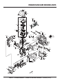
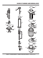
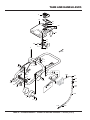
GUIDE CYLINDER AND SPRING ASSY.
2
32
1
20
3
9
22
21
24
12
8
14
27
18 17
28
25
29
26
13
15
16
23
29
9
27
28
25
26
7
4
6
5-2
5-1
24
31
51
30
52
53
PAGE 28 — MTX80/90 RAMMER — OPERATION AND PARTS MANUAL — REV. #9 (1/14/11)
GUIDE CYLINDER AND SPRING ASSY.
NO.
1
2
3
4
5-1
5-2
6
7
8
9
12
13
14
15
16
17
18
20
20
21
22
22
23
24
25
26
27
28
29
30
31
32
51
52
53
PART NO.
366460100
366459910
366346000
371459690
001221230
030212300
952404790
355447260
366459900
366459730
366345990
366217210
050100900
001521020
001521040
953405270
953405260
366217440
367217450
050710070
002211035
002211045
354010010
050931500
354336352
354442340
001220840
020308060
354446170
953405270
953405260
050200950
366118590
366460300
953404670
PART NAME
QTY.
REMARKS
PISTON PIN
1
PLUG, PISTON PIN
2
PISTON ROD
1
PISTON END
1
BOLT 12X30 T
1
WASHER, LOCK M12
1
WASHER 13306
1
STOPPER, LOWER
1
STOPPER, BOTTOM
1
MAIN SPRING
2
SPRING CYLINDER
1
FOOT PLATE 12
1
O-RING G-90
1
SOCKET HEAD BOLT 10X20 T
4
SOCKET HEAD BOLT 10X40 T
4
PLUG 1/4X14 13L
1
PACKING 1/4 (CU)
1
GUIDE CYLINDER ...................................... 1 .......... FOR MTX80
GUIDE CYLINDER ...................................... 1 .......... FOR MTX90
O-RING AS568-344
1
BOLT 10X35 H, SW .................................... 4 .......... FOR MTX80
BOLT 10X45 H, SW .................................... 4 .......... FOR MTX90
BELLOWS, ORANGE
1
O-RING JASO3150
2
BELLOWS CLAMP( 1.6T)171D
2
BAND GUIDE, BELLOWS
2
BOLT 8X40 T
2
NUT M8
2
PIN 6D-8.5L
2
PLUG 1/4X14 13L
1
PACKING 1/4 (CU)
1
O-RING P-95
1
PROTECTION SLEEVE
1
OIL GAUGE ASSY
1
COPPER PACKING 17X25.5X1
1
MTX80/90 RAMMER — OPERATION AND PARTS MANUAL — REV. #9 (1/14/11) — PAGE 29
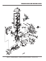
FOOT ASSY.
2
3
6
2
3
8
7
1
9
4
5
PAGE 30 — MTX80/90 RAMMER — OPERATION AND PARTS MANUAL — REV. #9 (1/14/11)
FOOT ASSY.
NO.
1
2
3
4
5
6
7
8
9
PART NO.
366910020
022711214
030212300
009110034
009110035
363343390
015110055
030210250
021110120
PART NAME
FOOT ASSY 285
NYLON NUT M12
WASHER, LOCK M12
BOLT, SQUARE NECK 12X65
BOLT, SQUARE NECK 12X95
GRIP HANDLEBAR
SUNK HEAD BOLT 10X55 H
WASHER SW M10
NYLON NUT M10
QTY.
1
4
4
2
2
1
7
7
7
REMARKS
MTX80/90 RAMMER — OPERATION AND PARTS MANUAL — REV. #9 (1/14/11) — PAGE 31
TANK AND HANDLE ASSY.
9
10
54
51
53
56
22
14
15
110
16
B
A
18
17
3
55
12
11-2
11-1
4-1
4-2
6
43
5
41
42
12
11-2
11-1
7
13
11-2
11-1
43
B
112
111
20 19
A
4-2
4-1
102
101
102
103
20
41
102
104
113
42
112
106
1
2-2
2-1
102
105
PAGE 32 — MTX80/90 RAMMER — OPERATION AND PARTS MANUAL — REV. #9 (1/14/11)
TANK AND HANDLE ASSY.
NO.
PART NO.
PART NAME
1
2-1
2-2
3
4-1
4-2
5
6
7
9
10
11-1
11-2
12
13
14
15
16
366346270
001521020
033121009
367119050
001211020
030210250
939010270
030208200
020308060
366900020
366118700
001210815
030208200
952401450
031108160
959300770
366459790
366345280
16%
366345280
17
18
19
020305040
030205130
959026122
19
0851041780
20
954406420
20
0561080020
22
41
42
43
009110037
366217170
091005020
022610505
SHOCK ABSORBER W/PIN
2
SOCKET HEAD BOLT 10X20 T
4
TOOTHED LOCK WASHER B M10
4
HANDLE
1
BOLT 10X20 H
4
WASHER, LOCK M10
4
STOPPER RUBBER (70)
1
WASHER, LOCK M8
1
NUT M8
1
CAP ASSY, FUEL TANK
1
FUEL TANK
1
BOLT 8X15 H
3
WASHER, LOCK M8
3
WASHER 8.5X22X3
2
WASHER, FLAT M8
1
STRAINER #508
1
PACKING, FUEL TANK
1
HOLDER, FILTER ................................... 1 ......... MTX80 S/N T-4419 AND BELOW
............................................................................. MTX90 S/N T-1341 AND BELOW
HOLDER, FILTER ................................... 1 ......... MTX80 S/N T-4420 AND ABOVE
............................................................................. MTX90 S/N T-1342 AND ABOVE
NUT M5
3
WASHER, LOCK M5
3
FUEL HOSE L=70 ................................... 1 ......... MTX80 S/N T-4164 AND BELOW
............................................................................. MTX90 S/N T-1331 AND BELOW
FUEL HOSE FOR EVP L=70 .................. 1 ......... MTX80 S/N T-4165 AND ABOVE
............................................................................. MTX90 S/N T-1332 AND ABOVE
HOSE BAND 10.5 ................................... 2 ......... MTX80 S/N T-4164 AND BELOW
............................................................................. MTX90 S/N T-1331 AND BELOW
HOSE CLAMP ........................................ 2 ......... MTX80 S/N T-4165 AND ABOVE
............................................................................. MTX90 S/N T-1332 AND ABOVE
TAPPING SCREW 5X20
2
ROLLER
2
SCREW 5X20
4
FLANGE NUT M5 H
4
QTY.
REMARKS
MTX80/90 RAMMER — OPERATION AND PARTS MANUAL — REV. #9 (1/14/11) — PAGE 33
TANK AND HANDLE ASSY.
9
10
54
51
53
56
22
14
15
110
16
B
A
18
17
3
55
12
11-2
11-1
4-1
4-2
6
43
5
41
42
12
11-2
11-1
7
13
11-2
11-1
43
B
112
111
20 19
A
4-2
4-1
102
101
102
103
20
41
102
104
113
42
112
106
1
2-2
2-1
102
105
PAGE 34 — MTX80/90 RAMMER — OPERATION AND PARTS MANUAL — REV. #9 (1/14/11)
TANK AND HANDLE ASSY.
CONTINUED
NO.
PART NO.
PART NAME
51
53
54
55
56
101
955010311
955010305
366345620
454010020
954010270
959026121
101
0851041800
102
954406420
102
0561080020
103
104
26365012A3
959021722
104
0851041760
105
959021824
106
110
959407720
366900060
111%
959028301
112%
954408170
113%
959021814
TP22 TACHO/HOUR METER
1
CURL CORD TP22
1
FINISHER, METER
1
CLAMP, TC100
5
CLIP AB-3N
1
FUEL HOSE L=170 ................................. 1 ......... MTX80 S/N T-4164 AND BELOW
............................................................................. MTX90 S/N T-1331 AND BELOW
FUEL HOSE FOR EVP L=170 ................ 1 ......... MTX80 S/N T-4165 AND ABOVE
............................................................................. MTX90 S/N T-1332 AND ABOVE
HOSE BAND 10.5 ................................... 4 ......... MTX80 S/N T-4164 AND BELOW
............................................................................. MTX90 S/N T-1331 AND BELOW
HOSE CLAMP ........................................ 4 ......... MTX80 S/N T-4165 AND ABOVE
............................................................................. MTX90 S/N T-1332 AND ABOVE
FILTER, FUEL CP
1
FUEL HOSE L=250
1
MTX80 S/N T-4164 AND BELOW
............................................................................. MTX90 S/N T-1331 AND BELOW
FUEL HOSE FOR EVP L=260 ................ 1 ......... MTX80 S/N T-4165 AND ABOVE
............................................................................. MTX90 S/N T-1332 AND ABOVE
SPIRAL TUBE D=6, L=110 ..................... 1 ......... MTX80 S/N T-4165 AND ABOVE
............................................................................. MTX90 S/N T-1332 AND ABOVE
TUBE, V 11X13X180
1
PRIMER PUMP KIT/NO CARB .............. 1 ......... INCLUDES ITEMS W/ %
............................................................................. MTX80 S/N T-4420 AND ABOVE
............................................................................. MTX90 S/N T-1342 AND ABOVE
RETURN HOSE 3X6X600....................... 1 ......... MTX80 S/N T-4420 AND ABOVE
............................................................................. MTX90 S/N T-1342 AND ABOVE
HOSE CLIP 5 .......................................... 2 ......... MTX80 S/N T-4420 AND ABOVE
............................................................................. MTX90 S/N T-1342 AND ABOVE
SPIRAL TUBE 6D-200L .......................... 1 ......... MTX80 S/N T-4420 AND ABOVE
............................................................................. MTX90 S/N T-1342 AND ABOVE
QTY.
REMARKS
MTX80/90 RAMMER — OPERATION AND PARTS MANUAL — REV. #9 (1/14/11) — PAGE 35
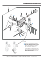
COMBINATION LEVER ASSY.
A
4
7
8
3
7
11
1
13
10
2
BODY
5
14
11
6
12
9
NOTES
OLD
STYLE
LEVER
NEW
STYLE
LEVER
OLD STYLE LEVER BODY NO LONGER
AVAILABLE. NEW STYLE ITEMS 1, 2, AND 9
ARE NOT COMPATIBLE WITH OLD STYLE
BODY. IF REPLACEMENT OF ITEMS 1, 2
OR 9 IS REQUIRED, ORDER KIT “A”.
TO DETERMINE IF COMBINATION LEVER
ASSY IS OLD STYLE OR NEW STYLE, SEE
ITEM 2, LEVER. NEW STYLE LEVER HAS
MOLDED TAB AT BOTTOM.
MOLDED
TAB
PAGE 36 — MTX80/90 RAMMER — OPERATION AND PARTS MANUAL — REV. #9 (1/14/11)
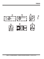
COMBINATION LEVER ASSY.
NO.
A
PART NO.
366900042
A
1
1#@
2
2#@
3#@
4#@
5#@
6#@
7#@
8#@
9
9#@
10#
11#@
12#@
13#@
14#@
956200110
366346260
366349430
366010180
366010310
366010190
366010200
366010210
366010220
020408050
959407650
366010260
366010320
956100063
094010051
094010052
050200150
050200110
PART NAME
QTY.
REMARKS
COMB. LEVER ASSY W/ THROTTLE WIRE ..... 1 ......... INCLUDES ITEMS W/ #
....................................................................................... REPLACES 366900041
COMB. LEVER ASSY ....................................... 1 ......... INCLUDES ITEMS W/@
FUEL COCK ...................................................... 1 ......... SEE NOTE ON DRAWING
FUEL COCK ...................................................... 1 ......... NEW STYLE, SEE NOTE ON DRAWING
LEVER ............................................................... 1 ......... SEE NOTE ON DRAWING
LEVER ............................................................... 1 ......... NEW STYLE, SEE NOTE ON DRAWING
SLIDER
1
END CAP
1
WIRE CAP
1
BOLT AND WASHER SET
1
NUT M8, H=5
2
SOCKET HEAD SCREW/TH.WIRE
1
STOP SWITCH .................................................. 1 ......... SEE NOTE ON DRAWING
STOP SWITCH .................................................. 1 ......... NEW STYLE, SEE NOTE ON DRAWING
THROTTLE WIRE
1
TAPPING SCREW B1 4X12
4
TAPPING SCREW B1 4X30
1
O-RING, P15
1
O-RING, P11
1
MTX80/90 RAMMER — OPERATION AND PARTS MANUAL — REV. #9 (1/14/11) — PAGE 37
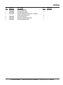
TOOLS
PAGE 38 — MTX80/90 RAMMER — OPERATION AND PARTS MANUAL — REV. #9 (1/14/11)
TOOLS
NO.
1
2
3
4
5
6
7
PART NO.
981010400
983010060
983910090
009110044
983910020
983010040
983910010
PART NAME
CLUTCH PULLER A
CLUTCH MOUNTER
PISTON ROD HOLDER
SOCKET HEAD BOLT 8X50 (FULL THREAD)
CRANK GEAR REMOVER
CLUTCH PULLER B
SPRING CYLINDER REMOVER
PISTON END REMOVER
QTY.
1
1
1
REMARKS
2
1
1
1
MTX80/90 RAMMER — OPERATION AND PARTS MANUAL — REV. #9 (1/14/11) — PAGE 39
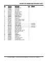
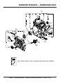
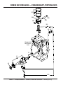
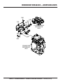
ROBIN EH122D46530 — CRANKCASE ASSY.
10
40
50
30
700
830
294
210
298
295
230
860
297
265
75
270
280
90
260
250
80
220
300
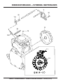
NOTE
USE LIQUID GASKET FOR CYLINDER AND INSULATOR GASKET.
PAGE 40 — MTX80/90 RAMMER — OPERATION AND PARTS MANUAL — REV. #9 (1/14/11)
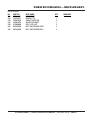
ROBIN EH122D46530 — CRANKCASE ASSY.
CRANKCASE ASSY.
NO.
10
30#
40#
50#
75#
80
90
210
220$
230$
250
260
265$
270
280
294
295
297
298
300
700
830
860
PART NO.
2521030141
0440250150
0600250100
0310060020
0440080010
0401140030
0211140020
2521110301
0440250160
0600250010
2274500301
2054190103
0108100030
2686360301
X213160020
2521700201
2521700101
0011308160
0011308160
0130060200
0310060020
2681620103
0011306160
PART NAME
QTY.
REMARKS
CRANKCASE CP...............................................1................INCLUDES ITEMS W/ #
OIL SEAL
1
BALL BEARING
1
DOWEL PIN
2
OIL SEAL VC 8X14X4
1
PLUG
2
GASKET
2
MAIN BEARING COVER CP .............................1................INCLUDES ITEMS W/ $
OIL SEAL
1
BALL BEARING 6205C3
1
GOVERNOR GEAR CP
1
GOVERNOR SLEEVE
1
STUD
2
OIL GAUGE CP
1
GASKET
1
BRACKET CP (M.B.C)
1
SUPPORT (M.B.C)
1
BOLT AND WASHER ASSY
1
BOLT AND WASHER ASSY
2
BOLT AND WASHER ASSY
8
DOWEL PIN
2
GASKET, BREATHER COVER
1
BOLT AND WASHER ASSY
2
MTX80/90 RAMMER — OPERATION AND PARTS MANUAL — REV. #9 (1/14/11) — PAGE 41
ROBIN EH122D46530 — CYLINDER HEAD ASSY.
710
850
680
MTX80/MTX90 — EH12-2D ROBIN ENGINE— CRANKSHAFT AND PISTON
690
910
726
723
722
721
720
724
690
725
230
610
20
26
20
220
95
73
72
230
70
220
95
73
72
630
71
260
240
60
210
900
901
60
240
620
CYLINDER HEAD
REFERENCE
ONLY
90
80
CRANKCASE
REFERENCE
ONLY
PAGE 42 — MTX80/90 RAMMER — OPERATION AND PARTS MANUAL — REV. #9 (1/14/11)
ROBIN EH122D46530 — CYLINDER HEAD ASSY.
CYLINDER HEAD ASSY.
NO.
20#
26
60#
70#
71#
72
73
80
90
95
210
220
230
240
260
610
620
630
680
690
710
720
721$
722$
723$
724$
725$
726$
850
900
901
910
PART NO.
2371420203
2771601001
0105080480
0105060131
0013906600
2533360103
2693370103
2683340103
2683350103
13210KA031
2683530103
2693600103
2693580103
0170060090
2693650103
2681310121
2531500133
0110080100
2521550203
2691600403
0110060170
2521560120
2521560113
2521600103
2521610103
2521440123
0110060150
0043506120
2681800503
0566000250
0110060020
0561120040
PART NAME
QTY.
REMARKS
VALVE GUIDE O/S
2
— E— CRANKSHAFT
AND PISTON
STEM SEAL
1
STUD
2
STUD
1
STUD
1
VALVE SPRING
2
SPRING RETAINER
2
INTAKE VALVE
1
EXHAUST VALVE
1
COLLET VALVE
4
PUSH ROD
2
ROCKER ARM
2
BOLT, PIVOT
2
NUT
2
GUIDE PLATE
1
CYLINDER HEAD CP ........................................1................INCLUDES ITEMS W/ #
GASKET, HEAD
1
FLANGE BOLT
4
ROCKER COVER
1
GASKET, ROCKER, COVER
2
FLANGE BOLT
4
SPACER ASSY, BREATHER ..............................1................INCLUDES ITEMS W/ $
SPACER, BREATHER
1
LEAF VALVE
1
RETAINER PLATE
1
PLATE
1
FLANGE BOLT
2
SCREW AND WASHER
1
RUBBER PIPE
1
CLAMP
1
FLANGE BOLT
1
HOSE CLAMP
1
MTX80/90 RAMMER — OPERATION AND PARTS MANUAL — REV. #9 (1/14/11) — PAGE 43
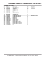
ROBIN EH122D46530 — CRANKSHAFT, PISTON ASSY.
370
360
380
380
350
310
60
50
CRANKCASE
REFERENCE
ONLY
70
10
40
320
PAGE 44 — MTX80/90 RAMMER — OPERATION AND PARTS MANUAL — REV. #9 (1/14/11)
ROBIN EH122D46530 — CRANKSHAFT, PISTON ASSY.
CRANKSHAFT, PISTON ASSY.
NO.
10
40
40
40
50
60
70
310
320#
350
360
360
360
370
370
370
380
PART NO.
2682190501
0230250110
0230250120
0230250130
0021814000
0032014000
0323030010
2522250120
2362300103
2682330103
26823401H3
26823402H3
26823403H3
2522350117
2522350217
2522350317
2152500403
PART NAME
QTY.
REMARKS
CRANK SHAFT CP
1
SPACER T=0.6
1
SPACER T=0.8
1
SPACER T=1.0
1
NUT
1
SPRING WASHER
1
WOODRUFF KEY
1
CONNECTING ROD ASSY ...............................1................INCLUDES ITEM W/ #
CONNECTING ROD BOLT
2
PISTON PIN
1
PISTON STD
1
PISTON O.S. 0.25
1
PISTON O.S. 0.5
1
PISTON RING SET, STD
1
PISTON RING SET 0.25 O.S.
1
PISTON RING SET 0.50 O.S.
1
CLIP
2
MTX80/90 RAMMER — OPERATION AND PARTS MANUAL — REV. #9 (1/14/11) — PAGE 45
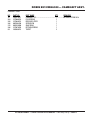
ROBIN EH122D46530 — CAMSHAFT ASSY.
CRANKCASE
REFERENCE
ONLY
10
36 34 38
50
PAGE 46 — MTX80/90 RAMMER — OPERATION AND PARTS MANUAL — REV. #9 (1/14/11)
ROBIN EH122D46530 — CAMSHAFT ASSY.
CAMSHAFT ASSY.
NO.
10
34#
35#
36#
37#
38#
50
PART NO.
2533170111
2273860123
2273640113
0051904100
0031522000
2273870103
2393330113
PART NAME
QTY.
REMARKS
CAMSHAFT CP .................................................1................INCLUDES ITEMS W/ #
PIN (SPRING)
1
RELEASE LEVER
1
SPRING PIN
1
SNAP RING
1
RETURN SPRING
1
TAPPET
2
MTX80/90 RAMMER — OPERATION AND PARTS MANUAL — REV. #9 (1/14/11) — PAGE 47
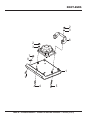
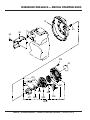
ROBIN EH122D46530 — RECOIL STARTER ASSY.
10
40
95
90
220
20
249
207
205
206
201
205
211
208
203
202
204
200
PAGE 48 — MTX80/90 RAMMER — OPERATION AND PARTS MANUAL — REV. #9 (1/14/11)
ROBIN EH122D46530 — RECOIL STARTER ASSY.
RECOIL STARTER ASSY.
NO.
10
20
40
90
95
200
201#
202#
203#
204#
205#
206#
207#
208#
211#
220
249#
PART NO.
2525165221
920100240
0011406550
2685270303
0110060140
2685020130
2705011508
2695012008
2825011118
2615010008
2705012508
2275013108
2275013508
2705026108
2685014518
0110060010
2275015208
PART NAME
QTY.
REMARKS
BLOWER HOUSING CP
1
DECAL, (M-MARK)
1
BOLT AND WASHER ASSY 6X55
4
HEAD COVER
1
FLANGE BOLT
2
RECOIL STARTER ASSY ..................................1................INCLUDES ITEMS W/ #
SPIRAL SPRING
1
REEL
1
STARTER ROPE
1
STARTER KNOB
1
RATCHET
2
FRICTION SPRING
1
RETURN SPRING
2
RATCHET GUIDE
1
STARTER PULLEY
1
FLANGE BOLT
4
SET SCREW
1
MTX80/90 RAMMER — OPERATION AND PARTS MANUAL — REV. #9 (1/14/11) — PAGE 49
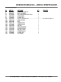
ROBIN EH122D46530 — CARBURETOR ASSY.
210
918
947
946
945
948 905
949
903
929
917
907
902
921
909
910
912
919
917
904
NOT SOLD SEPARATELY
943
900
927
925
906
916
908
920
926
915
911
914
901
916
PAGE 50 — MTX80/90 RAMMER — OPERATION AND PARTS MANUAL — REV. #9 (1/14/11)
ROBIN EH122D46530 — CARBURETOR ASSY.
CARBURETOR ASSY.
MTX80: S/N T-4419 AND BELOW
MTX90: S/N T-1341 AND BELOW
NO.
210
900#
901#
902#
903#
904#
905#
906#
907#
908#
909#
910#
911#
912#
914#
915#
916#
917#
918#
919#
920#
921#
925#
926#
927#
929#
943#
945#
946#
947#
948#
949#
PART NO.
2526257100
5016004010
2526260508
2526260408
2526261208
1616233508
2846260308
5106045040
2846260408
1616255208
1476258408
1616238008
1616238108
2526261008
1616238308
1066257508
1066257608
1476257308
2846260008
1616245408
1616245108
1476258308
1616236808
1616236908
1476257508
1616238508
2526261108
1616255108
2526260308
1616255308
2526260208
2526260108
PART NAME
QTY.
REMARKS
CARBURETOR ASSY ...................................... 1 ............... INCLUDES ITEMS W/ #
SCREEN INLET
1
COVER, METALING DIAPHRAGM
1
COVER PUMP
1
THROTTLE SHAFT
1
VALVE THROTTLE
1
SHAFT ASSY CHOKE
1
CLIP
1
VALVE, CHOKE
1
VALVE, INLET NEEDLE
1
BALL
1
GASKET PLUG
1
GASKET, METALING DIAPHRAGM
1
DIAPHRAGM PUMP
1
DIAPHRAGM ASSY, METALING
1
SCREW
1
SCREW ASSY
5
SCREW
2
SCREW
1
SPRING, IDLE ADJUST
1
SPRING, METALING LEVER
1
SPRING, CHOKE
1
PIN, METALING LEVER
1
LEVER, METALING
1
PLUG
1
SCREW, IDLE ADJUST
1
SPRING PUMP
1
STOPPER, THROTTLE
1
LEVER, THROTTLE
1
SCREW VALVE
2
SPACER, THROTTLE LEVER
1
WASHER
1
MTX80/90 RAMMER — OPERATION AND PARTS MANUAL — REV. #9 (1/14/11) — PAGE 51
ROBIN EH122D46530 — CARBURETOR ASSY.
PAGE 52 — MTX80/90 RAMMER — OPERATION AND PARTS MANUAL — REV. #9 (1/14/11)
ROBIN EH122D46530 — CARBURETOR ASSY.
CARBURETOR ASSY.
MTX80: S/N T-4420 AND ABOVE
MTX90: S/N T-1342 AND ABOVE
NO.
210
900#
901#
902#
903#
904#
905#
906#
907#
908#
909#
910#
911#
912#
914#
915#
916#
917#
918#
919#
920#
921#
925#
926#
927#
929#
943#
945#
946#
947#
948#
949#
950#
961#
962#
PART NO.
2526257300
5016004010
2526261608
2526261308
2526261208
1616233508
2846260308
5106045040
2846260408
1616255208
1476258408
1616238008
2526261808
2526261008
2526261708
2526261908
2526262008
1476257308
2846260008
1616245408
1616245108
1476258308
1616236808
1616236908
1476257508
1616238508
2526261108
1616255108
2526260308
1616255308
2526260208
1476258600
1066257608
2526261408
2526261508
PART NAME
CARBURETOR ASSY
SCREEN INLET
COVER, PRIMER PUMP
COVER PUMP
THROTTLE SHAFT
VALVE THROTTLE
SHAFT ASSY CHOKE
CLIP
VALVE, CHOKE
VALVE, INLET NEEDLE
BALL
GASKET PLUG
GASKET, METALING DIAPHRAGM
DIAPHRAGM PUMP
DIAPHRAGM ASSY, METALING
SCREW
SCREW ASSY
SCREW
SCREW
SPRING, IDLE ADJUST
SPRING, METALING LEVER
SPRING, CHOKE
PIN, METALING LEVER
LEVER, METALING
PLUG
SCREW, IDLE ADJUST
SPRING PUMP
STOPPER, THROTTLE
LEVER, THROTTLE
SCREW VALVE
SPACER, THROTTLE LEVER
SEAL, DUST
SCREW ASSY
BODY ASSY, AIR PURGE
PUMP, PRIMER
QTY.
1
1
1
1
1
1
1
1
1
1
1
1
1
1
1
1
5
2
1
1
1
1
1
1
1
1
1
1
1
2
1
2
1
1
1
REMARKS
INCLUDES ITEMS W/ #
MTX80/90 RAMMER — OPERATION AND PARTS MANUAL — REV. #9 (1/14/11) — PAGE 53
ROBIN EH122D46530 — AIR CLEANER ASSY.
555
590
556 552
567
500
550
CYLINDER HEAD
REFERENCE
ONLY
528
565
563
560
570
530
PAGE 54 — MTX80/90 RAMMER — OPERATION AND PARTS MANUAL — REV. #9 (1/14/11)
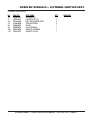
ROBIN EH122D46530 — AIR CLEANER ASSY.
AIR CLEANER ASSY.
NO.
500
528
530
550
552
555
556
560
563
565
567
570
590
PART NO.
2683300413
2683660103
2843810103
1573500103
2843650103
2823590103
0011406400
1066500203
0119060090
2843310103
0100050110
0176050010
0023806000
PART NAME
INTAKE PIPE
PLATE
INTAKE PIPE
GASKET, INSULATOR
GASKET (INTAKE)
GASKET, INSULATOR
BOLT AND WASHER ASSY
GASKET (CARB.)
BOLT (SOCKET HEAD)
INTAKE FLANGE CP
BOLT M5X0.8X70L
SELF LOCK NUT
FLANGE NUT
QTY.
1
1
1
1
1
1
1
2
2
1
2
2
2
REMARKS
MTX80/90 RAMMER — OPERATION AND PARTS MANUAL — REV. #9 (1/14/11) — PAGE 55
ROBIN EH122D46530 — MUFFLER ASSY.
366
310
340
345
340
CYLINDER HEAD
REFERENCE
ONLY
350
330
365
CRANKCASE
REFERENCE
ONLY
PAGE 56 — MTX80/90 RAMMER — OPERATION AND PARTS MANUAL — REV. #9 (1/14/11)
ROBIN EH122D46530 — MUFFLER ASSY.
MUFFLER ASSY.
NO.
310
330
340
345
350
365
366
PART NO.
2523040111
2523700111
2533520103
2523650123
0176080020
0011308160
0011408160
PART NAME
MUFFLER CP
BRACKET CP
GASKET, MUFFLER
SPACER, EXHAUST
SELF LOCK NUT
BOLT AND WASHER ASSY
BOLT AND WASHER 8X16
QTY.
1
1
2
1
2
2
2
REMARKS
MTX80/90 RAMMER — OPERATION AND PARTS MANUAL — REV. #9 (1/14/11) — PAGE 57
ROBIN EH122D46530 — GOVERNOR ASSY.
40
30
20
80
280
26
50
200
70
210 230
240
60
710
10
235
290
231
715
293
PAGE 58 — MTX80/90 RAMMER — OPERATION AND PARTS MANUAL — REV. #9 (1/14/11)
716
ROBIN EH122D46530 — GOVERNOR ASSY.
GOVERNOR ASSY.
NO.
10
20
26
30
40
50
60
70
80
200
210
230
231
235
240
280
290
293
710
715
716
PART NO.
2524230303
2274220103
0031108000
2544270101
2544280103
0031306000
0011406300
0186060020
2524250323
2524340230
0116040030
0043105250
0043104250
2684500113
0021705000
2264310101
2684420201
0110060030
2524280111
0011308160
0110060030
PART NAME
GOVERNOR LEVER CP
GOVERNOR SHAFT
WASHER
GOVERNOR ROD CP
ROD SPRING
CLIP
BOLT AND WASHER ASSY
NUT
GOVERNOR SPRING
SPEED CONTROL ASSY
BOLT
SCREW, PANHEAD
SCREW
CONTROL SPRING
NUT
LINK PIVOT CP
WIRE BRACKET
FLANGE BOLT
PROTECTOR CP, GOVERNOR
BOLT AND WASHER ASSY
FLANGE BOLT
QTY.
1
1
1
1
1
2
1
1
1
1
1
1
1
1
1
1
1
1
1
1
1
REMARKS
MTX80/90 RAMMER — OPERATION AND PARTS MANUAL — REV. #9 (1/14/11) — PAGE 59
ROBIN EH122D46530 — FLYWHEEL IGNITION ASSY.
11
30
95
110
10
90
70
100
11
10
PAGE 60 — MTX80/90 RAMMER — OPERATION AND PARTS MANUAL — REV. #9 (1/14/11)
ROBIN EH122D46530 — FLYWHEEL IGNITION ASSY.
FLYWHEEL IGNITION ASSY.
NO.
10
11
30
70
90
95
100
110
PART NO.
2687933201
2697943011
0011406250
0150040090
0566000250
0659000010
0650140580
2307510113
PART NAME
FLYWHEEL CP
IGNITION COIL CP
BOLT AND WASHER ASSY
TAPPING SCREW
CLAMP
PLUG TERMINAL
SPARK PLUG BR6ES
SPARK PLUG CAP
QTY.
1
1
2
2
1
1
1
1
REMARKS
MTX80/90 RAMMER — OPERATION AND PARTS MANUAL — REV. #9 (1/14/11) — PAGE 61
ROBIN EH122D46530 — LABELS AND ACCESSORIES
LABELS
100
101
102
103
ACCESSORIES
201
202
PAGE 62 — MTX80/90 RAMMER — OPERATION AND PARTS MANUAL — REV. #9 (1/14/11)
ROBIN EH122D46530 — LABELS AND ACCESSORIES
LABELS AND ACCESSORIES
NO.
100
101
102
103
201
202
PART NO.
0732004450
0732004520
0732003900
0732005020
0830000010
2267510103
PART NAME
LABEL, CAUTION
LABEL, OIL CAUTION
LABEL, WARNING
LABEL CHOKE
COIL SPRING
CLAMP
QTY.
1
1
1
1
1
1
REMARKS
MTX80/90 RAMMER — OPERATION AND PARTS MANUAL — REV. #9 (1/14/11) — PAGE 63
TERMS AND CONDITIONS OF SALE — PARTS
PAYMENT TERMS
5.
Parts must be in new and resalable
condition, in the original Multiquip
package (if any), and with Multiquip part
numbers clearly marked.
6.
The following items are not returnable:
Multiquip reserves the right to quote and
sell direct to Government agencies, and to
Original Equipment Manufacturer accounts
who use our products as integral parts of their
own products.
a.
SPECIAL EXPEDITING SERVICE
Terms of payment for parts are net 30 days.
FREIGHT POLICY
All parts orders will be shipped collect or
prepaid with the charges added to the invoice.
All shipments are F.O.B. point of origin.
Multiquip’s responsibility ceases when a
signed manifest has been obtained from the
carrier, and any claim for shortage or damage
must be settled between the consignee and
the carrier.
b.
MINIMUM ORDER
The minimum charge for orders from Multiquip
is $15.00 net. Customers will be asked for
instructions regarding handling of orders not
meeting this requirement.
RETURNED GOODS POLICY
Return shipments will be accepted and
credit will be allowed, subject to the following
provisions:
1.
2.
A Returned Material Authorization
must be approved by Multiquip prior to
shipment.
Obsolete parts. (If an item is in the
price book and shows as being
replaced by another item, it is
obsolete.)
Any parts with a limited shelf life
(such as gaskets, seals, “O” rings,
and other rubber parts) that were
purchased more than six months
prior to the return date.
c.
Any line item with an extended
dealer net price of less than
$5.00.
d.
Special order items.
e.
Electrical components.
f.
Paint, chemicals, and lubricants.
g.
Decals and paper products.
h.
Items purchased in kits.
7.
The sender will be notified of any material
received that is not acceptable.
To obtain a Return Material Authorization,
a list must be provided to Multiquip
Parts Sales that defines item numbers,
quantities, and descriptions of the items
to be returned.
8.
Such material will be held for five
working days from notification, pending
instructions. If a reply is not received
within five days, the material will be
returned to the sender at his expense.
a.
The parts numbers and descriptions
must match the current parts price
list.
9.
b.
The list must be typed or computer
generated.
Credit on returned parts will be issued
at dealer net price at time of the original
purchase, less a 15% restocking
charge.
c.
The list must state the reason(s)
for the return.
d.
The list must reference the sales
order(s) or invoice (s) under
which the items were originally
purchased.
e.
The list must include the name
and phone number of the person
requesting the RMA.
3.
A copy of the Return Material Authorization
must accompany the return shipment.
4.
Freight is at the sender’s expense. All
parts must be returned freight prepaid to
Multiquip’s designated receiving point.
10. In cases where an item is accepted, for
which the original purchase document
can not be determined, the price will be
based on the list price that was effective
twelve months prior to the RMA date.
A $35.00 surcharge will be added to the
invoice for special handling including bus
shipments, insured parcel post or in cases
where Multiquip must personally deliver the
parts to the carrier.
LIMITATIONS OF SELLER’S LIABILITY
Multiquip shall not be liable hereunder for
damages in excess of the purchase price of
the item with respect to which damages are
claimed, and in no event shall Multiquip be
liable for loss of profit or good will or for any
other special, consequential or incidental
damages.
LIMITATION OF WARRANTIES
No warranties, express or implied, are
made in connection with the sale of parts or
trade accessories nor as to any engine not
manufactured by Multiquip. Such warranties
made in connection with the sale of new,
complete units are made exclusively by a
statement of warranty packaged with such
units, and Multiquip neither assumes nor
authorizes any person to assume for it
any other obligation or liability whatever in
connection with the sale of its products. Apart
from such written statement of warranty,
there are no warranties, express, implied or
statutory, which extend beyond the description
of the products on the face hereof.
Effective: February 22, 2006
11. Credit issued will be applied to future
purchases only.
PRICING AND REBATES
Prices are subject to change without prior
notice. Price changes are effective on a
specific date and all orders received on or
after that date will be billed at the revised price.
Rebates for price declines and added charges
for price increases will not be made for stock
on hand at the time of any price change.
PAGE 64 — MTX80/90 RAMMER — OPERATION AND PARTS MANUAL — REV. #9 (1/14/11)
NOTES
NOTES
MTX80/90 RAMMER — OPERATION AND PARTS MANUAL — REV. #9 (1/14/11) — PAGE 65
OPERATION AND PARTS MANUAL
HERE’S HOW TO GET HELP
PLEASE HAVE THE MODEL AND SERIAL
NUMBER ON-HAND WHEN CALLING
UNITED STATES
Multiquip Corporate Office
18910 Wilmington Ave.
Carson, CA 90746
Contact: [email protected]
MQ Parts Department
Tel. (800) 421-1244
Fax (800) 537-3927
Service Department
800-421-1244
310-537-3700
800-427-1244
310-537-3700
Fax: 800-672-7877
Fax: 310-637-3284
Warranty Department
Fax: 310-537-4259
800-421-1244
310-537-3700
Fax: 310-943-2249
Technical Assistance
800-478-1244
Fax: 310-943-2238
MEXICO
UNITED KINGDOM
MQ Cipsa
Multiquip (UK) Limited Head Office
Carr. Fed. Mexico-Puebla KM 126.5
Momoxpan, Cholula, Puebla 72760 Mexico
Contact: [email protected]
Tel: (52) 222-225-9900
Fax: (52) 222-285-0420
Unit 2, Northpoint Industrial Estate,
Globe Lane,
Dukinfield, Cheshire SK16 4UJ
Contact: [email protected]
Tel: 0161 339 2223
Fax: 0161 339 3226
CANADA
Multiquip
4110 Industriel Boul.
Laval, Quebec, Canada H7L 6V3
Contact: [email protected]
Tel: (450) 625-2244
Tel: (877) 963-4411
Fax: (450) 625-8664
© COPYRIGHT 2011, MULTIQUIP INC.
Multiquip Inc, the MQ logo and the Mikasa logo are registered trademarks of Multiquip Inc. and may not be used, reproduced, or altered without written permission. All other trademarks
are the property of their respective owners and used with permission.
This manual MUST accompany the equipment at all times. This manual is considered a permanent part of the equipment and should remain with the unit if resold.
The information and specifications included in this publication were in effect at the time of approval for printing. Illustrations, descriptions, references and technical data contained in
this manual are for guidance only and may not be considered as binding. Multiquip Inc. reserves the right to discontinue or change specifications, design or the information published
in this publication at any time without notice and without incurring any obligations.
Your Local Dealer is: