1
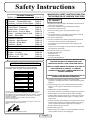
TM
Manufacturers of Britain’s Best Selling Range of Garden Tractors and Rider Mowers
D
Version 1.1
-DIESEL-
D18/50
Garden Tractor
OPERATORS MANUAL
Engine
Collector
Cutter Decks
Controls
Safety Instructions
Contents Summary:
Safety Instructions
Controls and Indicators
Controls - Forward/Reverse
Controls - Levers & Dash lights
Cutting Decks
Cutter Deck - Removal
Cutter Deck - Check List
Deck levels - Front to Back
Cutter - Levelling Side to Side
Cutter - Drive Belt
Powered Collector
Collector - Adjustments
Collector - Drive Belts
Collector - Brush
Tyres and Wheels
Electrical
Engine - Oil and Oil Filter
Engine - Cooling
Engine - Fuel & Air Filter
Transmission - Oil
Notes
Page
Page
Page
Page
Page
Page
Page
Page
Page
Page
Page
Page
Page
Page
Page
Page
Page
Page
Page
Page
Page
2,3
4
5
6
7
8
9
10
11
12
13
14
15
16
17
18
19
20
21
22
23
CERTIFICATE OF CONFORMITY
EC Declaration of Conformity
I, the undersigned R. Kilminster of Countax Limited,
Gt Haseley, Oxon. England, certify that lawnmowers:
MODEL
Power (K/w)
D18/50
11.93
Max Rotation of blades (rpm)
Engine Manufacturer
Engine Type
3100rpm
Yanmar
Diesel
Mass (Kg)
Max drawbar pull (Kg)
at coupling hook
on level ground
Max vertical load (Kg)
25
105 Db(A)
@ 3000rpm
Vibration (m/s/s) hands:
2.05
0.53
Rotary
127cm
Conforms to the specifications of Directive 84/583/EEC (as adapted to the
technical progress by Directive 87/252/EEC and amended by Directive
88/180/EEC and Directive 89/392/EEC (amended by 91/368/EEC, 93/44/EEC
and 93/68/EEC) and Directive 89/336/EEC and amended by 91/263/EEC
92/31/EEC, 98/37/EEC
Standards used BS5107, EN292, ISO3767, ISO3789, ISO3864
Tested at Oxford, England.
I declare that on behalf of Countax Limited these machines conform to EC
Essential Health and Safety Requirements
Signed:
R.Kilminster (Technical Director) 1/4/99
TRAINING
1. Read the instructions carefully. Be familiar with the controls
and the use of equipment.
2. Never allow children or people unfamiliar with these
instructions to use the mower.
3. Never mow while people, especially children or pets
are nearby.
4. The operator or user is responsible for accidents or hazards
occurring to other people or their property.
5. Do not carry passengers.
6. All drivers should seek to obtain professional and practical
instruction. Such instruction should emphasise:
• The need for care and concentration when working with
this machine.
• Control of a tractor sliding on a slope will not be regained by
the application of the brake.
The main reasons for loss of control are:
• Insufficient wheel grip.
• Driving too fast.
• Inadequate braking.
• Incorrect load distribution.
READ THE INSTRUCTION MANUAL BEFORE USING
THE GARDEN TRACTOR AND ENSURE THAT
OPERATORS STUDY IT FOR THEIR OWN SAFETY.
THE FOLLOWING PRECAUTIONS ARE OUTLINED TO
HELP PREVENT ACCIDENTS. A CAREFUL
OPERATOR WHO USES COMMON SENSE IS THE
SAFEST OPERATOR.
THESE SAFETY PRECAUTIONS ARE IN ADDITION TO
THOSE IN THE INSTRUCTION MANUAL.
290
650
Max sound power level
Vibration (m/s/s) seat:
Type of cutting device
Width of cutting device
MANDATORY SAFETY INSTRUCTIONS FOR
THE OPERATION OF GARDEN TRACTORS
1. Check that the machine complies with all applicable
regulations, including those in force when used on the public
highway.
2. When mowing always wear substantial footwear and long
trousers. Do not operate when barefoot or with open toe
sandals.
3. WARNING – Diesel is flammable:
• Store fuel in containers specifically designed for this purpose.
• Refuel outdoors only and do not smoke when refuelling.
• Add fuel before starting engine. Never remove the cap from
the fuel tank or add diesel while engine is running or when
engine is hot.
• If diesel is spilled, do not attempt to start engine but move the
machine away from the area of spillage and avoid creating a
source of ignition until diesel vapours have dissipated.
• Replace the fuel tank cap securely.
4. Replace faulty silencers.
5. Before using, always inspect to see that the blades, bolts and
cutter assembly are not worn or damaged.
Page 2
Safety Instructions
6. Check the condition of the tyres and ensure that they are
inflated to the correct pressure (refer to the specifications on
the back page of this manual). This is particularly important if
the machine is to be taken on the public highway.
7. Check the mower is in good working order, paying particular
attention to brakes and steering.
8. Check that all linkages, connections, and pivot nuts are secure
and that the wheel nuts are torqued correctly.
OPERATION
1. Do not operate the engine in a confined space where
dangerous fumes can collect.
2. Mow only in daylight or in good artificial light.
3. Before starting the engine, disengage blade and attachment
drives and ensure your feet are off all pedals.
4. Take care on slopes of more than 10º incline or decline
(maximum safe operation is at 15º).
5. Remember that there is no such thing as a ‘safe’ slope. Travel
on grass slopes requires particular care to guard against
overturning:
• Do not stop or start suddenly when going up or downhill.
• Machine speed should be kept low on slopes and in tight turns.
• Stay alert for humps and hollows and other hidden hazards.
• Avoid mowing across the face of the slope.
6. Watch for traffic when crossing or near roadways.
7. Stop the blades rotating before crossing surfaces other
than grass.
8. When using the machine, never direct discharge of material
towards bystanders or allow anyone near the machine while
in operation.
9. Never operate the mower with defective guards, shields or
without safety protective devices in place and in good
working order.
10. Do not change governor settings to increase the revs of the
engine. Operating the engine at excessive speed increases the
hazard of injury.
11. Before leaving the operators position:
• Disengage the drive to the cutter blades and attachments and
lower the attachments.
• Remove your foot from drive pedals and set the handbrake.
• Stop the engine and remove the key.
12. Disengage drive attachments, stop the engine and remove
ignition key before:
• Clearing blockages.
• Checking, cleaning or working on the mower.
• Refuelling.
• Removing the grass catcher.
• After striking a foreign object (inspect the mower for damage
and make repairs before restarting the tractor).
• If the machine starts to vibrate abnormally check immediately
and call dealer if necessary.
13. Disengage drive to attachments when transporting or
not in use.
14. Reduce the throttle setting during engine run-out.
15. Never work on the mower when the engine is running.
MAINTENANCE AND STORAGE
1. Check that all nuts, bolts and screws are tight to be sure the
equipment is in a safe working condition.
2. Allow the engine to cool before storing in any enclosure.
3. To reduce the risk of fire keep the engine, silencer and battery
compartment free of grass, leaves, petrol or excessive grease.
4. Check the grass catcher frequently for wear and tear or
deterioration.
5. Replace worn or damaged parts for safety.
6. If the fuel tank has to be drained, this should be done outdoors.
7. Be careful during adjustment of the machine to prevent
entrapment of fingers between moving blades and fixed
parts of the machine.
8. Do not use steam cleaners or high-pressure washers directly
towards the bearings or electrical components (Countax do not
recommend the use of these power cleaners). Incorrect use
could void warranty.
SUPPLEMENTARY INSTRUCTIONS FOR THE
USE OF COUNTAX D18/50 TRACTOR
1. Use good sense at all times and to ensure this tractor is safe
and serviceable, fit only original manufacturers
supplied spares.
2. When inspecting the area to be cut, note also the position of
any stumps, manhole covers, bumps and depressions and
avoid them to prevent damaging the blades.
3. We recommend the use of standard diesel and that you ensure
the fuel tank is full before you start the machine.
4. Always disconnect both battery terminals before attempting
any work in the engine compartment.
5. Do not leave the tractor unattended and running.
6. Do not put hands near moving belts or the Power Take-Off
pulley while it is rotating.
SAFETY SWITCHES
SEAT SAFETY SWITCH
Your Countax tractor is fitted with a switch that will turn OFF the
engine and the cutter deck should you dismount.
This is a safety back-up and should not be used voluntarily. If
you want to dismount from the tractor and want the engine to
continue running, first switch OFF the cutter deck, then apply
the parking brake. You can now dismount. DO NOT LEAVE
THE ENGINE IDLING FOR ANY LENGTH OF TIME. Should
you try and dismount with the parking brake ON, the cutter deck
will cut out after a short delay of a couple of seconds. Do not
rely on this back up cutout. Ensure safety by switching the
cutter deck off.
PARK BRAKE SAFETY SWITCH
Your Countax tractor is fitted with a safety switch activated by
the Park Brake lever. This switch earths the ignition unless the
brake is on. The engine will only start while the brake is
engaged. Two red lights on the dash (Ignition, and Brake)
indicate that the engine is ready to start.
N.B Both safety switches work on the fuel cut-out solenoid.
Should safety switches be activated, to re-start the tractor the ignition switch should be turned compleately off.
Page 3
Controls & Indicators - Dashboard
O
O
Light
Switch
Cutter
Engage Switch
Auxiliary
Lift Switch
Deck
Height Switch
Ignition
Switch
Engine
Speed
PGC Net
Empty Switch
fig 1
IGNITION
WARNING LIGHTS (fig 2)
The ‘Key Start’ controls both the ignition and the starter. Insert
the key and turn to the first position, the dash lights will come on
(check that all is ready to start). For starting from cold, turn the
key to the second ‘heat’ position and hold for 10 seconds. Turn
the key further to the third position to crank the engine, release
the key as soon as the engine is running and it will return back to
the first position. If the tractor is to be started from a hot engine,
pre-heating is not required.
CUTTER ON/OFF SWITCH
The cutter switch controls the Electromagnetic Blade Clutch. It
works like a light switch (but in reverse) – UP for ON and
DOWN for OFF. Although it always returns to the central
position and the cutter deck will automatically be turned off
when the engine is switched off, it is not good practice to rely on
this. The cutter deck should always be switched OFF as soon as
you have finished cutting and certainly BEFORE stopping the
engine or getting off the tractor.
1). Situated above the PGC net emptying switch are three
warning lights. The first (red) light is a charge light. This light
will illuminate when the key is turned to the first position, when
the engine is started the light will go out. If the light comes on
whilst the engine is running consult your dealer.
red
yellow
green
2). The second (yellow) light is a ‘high water temperature’
warning light. This light will only come on if the water
temperature becomes too high. Should this occur, stop the engine
straight away and allow to cool. When the engine has cooled,
check the water level in the radiator (see page 20) and top up
coolant as required. If the light stays illuminated – call your
dealer immediately.
3). The third (green) light is an ‘oil pressure’ warning light. This
light will come on when the key switch is turned to the first
position, and then go out when the engine is running. If the light
illuminates whilst the tractor is in use – stop the engine
immediately and contact your dealer before attempting to restart
your machine.
O
ENGINE SPEED CONTROL
The lever is pushed forward and up for high revs, back and down
for low. Please note, when in use the engine speed should be set
to maximum revs.
fig 2
Warning
Lights
2
HEADLIGHT SWITCH
1
Switching the rocker switch turns ON the headlights. The
headlights will not operate when the ignition is OFF. Turn the
headlights OFF before starting or stopping.
Page 4
3
Controls - Forward/Reverse
FOOTPEDAL CONTROLS / MOVING OFF (fig 1,2)
To move off, ensure your foot is off the pedals ‘A’ and ‘B’ then
disengage the parking brake by moving lever ‘C’ (fig 2) forward.
Now gently depress either pedal ‘A’ or ‘B’ (fig 1) to move off
forward or backward. The function of either pedal has the same
effect as the accelerator on a car except that it controls the
hydrostatic transmission and does not effect the speed of the
engine. N.B. The engine speed must be set to maximum
whenever the tractor is used. Never attempt to depress pedal ‘A’
and ‘B’ together as damage to the linkage may occur which will
not be covered by warranty.
REVERSING (fig 1)
To engage and control reversing simply take your foot off pedal
‘A’ – to avoid a rapid stop remove your foot gently. The tractor
will come to a standstill. When the tractor is stationary, depress
pedal ‘B’ to move backwards.
PARKING (fig 2)
fig 1
A
On no account
attempt to operate
either forward or
reverse pedals whilst
Parking brake is
engaged. This will
result in damage that
will not be covered by
warranty
B
fig 2
Remove your foot from pedal ‘A’ and ‘B’ and the tractor will
come to a standstill. Now engage the park brake by simply
moving lever ‘C’ (fig 2) rearward to an upright position- you will
feel the lever lock into this position.
C
EMERGENCY BRAKING (fig 1,2)
In case of an emergency remove your foot from the drive pedal
simultaneously engaging park brake lever ‘C’. The tractor will
stop abruptly.
Park Brake
‘On’
Park Brake
Released
DIFFERENTIAL LOCK (fig 3)
The D18/50 is fitted with a differential lock for maximum
traction on slopes and slippery ground. The differential lock
should only be used in situations where one wheel is slipping and
the other is not. In a situation when one wheel starts to slip and
extra traction is required simply depress pedal ‘D’ (fig 3) and the
differential will lock both wheels to drive at the same speed. As
soon as the differential lock is not required release the engage
pedal ‘D’ and as soon as the wheels are rotating at the same speed
and not under load (i.e. on a slope) the lock will automatically
release.
WARNING: Do not attempt to steer the tractor
when the differential lock is engaged. Always
ensure the differential lock is released before
manoeuvring in a closed area.
fig 3
D
Engaged
Position
fig 4
E
HYDROSTATIC BYPASS VALVE (fig 4)
To push or freewheel the D18/50, release the park brake then
disengage the hydrostatic transmission by releasing the bypass
valve. Simply pull the bypass valve lever ‘E’ (fig 4) outward.
You will now be able to push the tractor. Reset the bypass valve
by pushing the lever in BEFORE starting the tractor.
Hydrostatic
Bypass
Lever
Page 5
Controls - Levers & Dashlights
POWER TAKE-OFF (PTO) fig 1
Dashlights
E
D
Lift the lever to the LEFT and DOWN, letting it find its own
height to engage the PTO and UP and to the RIGHT to
disengage (fig 1). This is an ON/OFF lever for the PTO. Always
have this lever in the DISENGAGED POSITION when it is not
in use. Do not put hands near moving pulleys and belts.
A
ELECTRIC LIFTS
The cutting height is adjusted by pressing a rocker switch (A) on
the left of the dash panel (fig 4) UP for higher or DOWN for
lower. An illuminated indicator on the dash will show the
position and 10 indicated heights are shown for guidance
purposes only – the cutting height is in fact infinitely adjustable!
To get the best from this refinement use it to continuously adjust
cutting height to suit ground and grass conditions. Do not make
downward adjustments on the move until you are familiar with
this height control to avoid scalping.
B
(A)
(B)
(C)
(D)
(E)
PGC NET EMPTY SWITCH (fig 3)
A third switch is fitted to those tractors with a Powered Grass
Collector. This switch empties the collector net via an electric
actuator mechanism that lifts the grass box and pushes out the
bottom pan, fully emptying the collector contents. Press the
switch UP to open and DOWN to close the net (fig 3).
C
‘Cutter On’ indicator flashes continuously when cutter is
running.
The ‘Ignition On’ indicator goes out when the cutter
is running.
The ‘Brake On’ indicator.
The ‘Deck Height’ indicator.
The ‘Hour Meter’.
fig 3
O
SEAT ADJUSTMENT
The seat on the D18/50 is adjustable forwards and rearwards to
suit the operator. Simply lift the seat latch at the front of the seat
(fig 2) and slide the seat forwards or backwards to suit. Always
ensure the seat is latched back into position before driving off.
PGC Net
Empty Switch
fig 1
-D1850IMPORTANT - READ SAFETY INSTRUCTIONS BEFORE OPERATING THIS MACHINE
MULCHING
For Best results;
- Do not reduce the height of the grass by more than 1/3 in a single pass
- Mow often - short clippings of 25mm (1") or less decompose more quickly
- If possible, avoid cutting in the wet
- Always cut with the engine at full running speed
- If an unsightly residue is present - increase cutting height
- Vary mowing pattern from cut to cut
- Always keep the underside of the deck clean to permit good grass flow
- Always ensure that blades are sharp and in good condition
15 MAX
O
15 MAX
EXERCISE CAUTION WHEN CUTTING
ON SLOPES
VIBRATION TESTED TO THE FOLLOWING STANDARDS
BS 6842:1987, DD ENV 25349:1993, SI 1992:3073, BS6841:1987
fig 2
Power
Take-off Lever
fig 4
O
PTO
Seat
Adjustment Latch
O
Deck Height
Switch
Page 6
Cutting Decks
MULCH MOWING
Mulching can save time, avoids gathering piles of rotting
cuttings and feeds your lawn. It is however necessary to observe
certain rules to mulch mow successfully:
• Reduce the height in each pass. If the grass has grown long
make several passes to achieve the cut height you require.
• Always cut with the throttle set to FAST – mulching needs the
full running speed of the engine.
• Mow often, particularly in spring and early summer. Short
clippings of 25mm (1") or less decompose more quickly.
• If possible avoid cutting in the wet.
• If an unsightly residue of cuttings is being left – increase the
cutting height.
• Vary the mowing pattern from cut to cut.
• Always keep the underside of the cutting deck clean to ensure
good grass flow.
• Always check that the blades are sharp and in good condition
– but do not attempt to sharpen or replace them yourself. New
Countax blades are not expensive and it is good practice to ask
your dealer to change them regularly.
fig 1
Mulch Deck
Pulley
Arrangement
fig 2
Mulch Deck
Blade
Arrangement
fig 3
Mulching
Process
fig 4
IBS Deck
Pulley
Arrangement
REAR DISCHARGE DECK
The Countax IBS Rear Discharge deck in contrast to the Mulch
Deck, finely cuts the grass and then ejects it rearwards where it is
collected by the Powered Grass Collector. This system offers the
benefit of the ‘striped lawn’ finish to your garden and tidies loose
leaves and garden debris from your lawn.
Specified Belts and Blades
Part:
Part No.
Engine/Deck Belt Dayco Super II B56 (Mulcher)
22871200
Engine/Deck Belt Dayco Super II B57 (IBS)
22940100
Deck Internal Drive (Mulcher)
BB112
228000900
Deck Internal Drive (IBS)
BB155
22950200
Mulcher Blades x3
16938100
IBS RH Blade
169381300
IBS LH Blade
169381400
PGC Drive Belt A47
22898000
PTO Drive Belt - Dayco II A98
22950100
Transmission Drive Belts A98
Dayco Super II
2295000
Remember - only use specified Belts
and Blades. Never accept a substitute!
Page 7
Cutter Deck - Removal
Either the Mulch Deck or the Rear Discharge Deck can be fitted
to the D18/50 using the following instructions:
fig 1
D
C
F
REMOVAL OF CUTTER DECK
The cutter deck can be quickly removed for servicing or cleaning
or to give greater clearance when driving or towing over uneven
ground.
Follow this sequence:
1. Put the cutter to the lowest position (see page 6).
2. De-tension the cutter drive belt with the lever situated under
the left (nearside) running board (fig 6).
3. Remove the 3 securing pins from the front of the deck
(fig 3 – A, B and C) by pulling out the spring clips.
4. Remove the 2 securing pins from the back of the deck
(fig 2 – D and E).
5. Slip the cutter drive belt off the engine pulley.
6. Slide the deck out.
7. If you are going to use the tractor without the deck, remove the
securing bar (F).
B
A
E
fig 2
C
D
When replacing the cutter deck, re-tension the belt with the lever
under the running board. Then check the belt tension (page 12).
F
TO CLEAN CUTTER DECK
Remove the deck as instructed, stand it on its side and hose off
accumulated cuttings. This may be necessary routinely to prevent
build-up of cuttings particularly at the beginning of the season
when the grass is lush and wet. Thoroughly wash the underside
of the cutter deck as regularly as possible.
B
E
A
ENGINE TO CUTTER DRIVE BELT
REPLACEMENT
fig 3
Follow this sequence:
1. Pull the belt tension lever (fig 6) forward.
2. Lower the cutter deck to the lowest position.
3. Remove the cutter deck as described above.
4. Remove belt guard, loosen the two M8 set screws using
using a 13mm spanner and socket.
5. Remove the belt from the pulley and fit replacement.
6. Refit the belt guard ensuring that it is clear of the belt
and pulley.
7. Refit the cutter deck to the tractor and re-tension the deck
drive belt as described on page 12.
fig 4
fig 5
Unsecured
The belts fitted to your tractor are of a special
construction and belt tensions have been precisely
set in the factory. If you undertake to replace a belt
yourself you must be VERY careful that the
correct Countax supplied belt is used and that the
tension is set accurately.
Secured
fig 6
i
-Use only genuine Countax parts-
Actuator
Page 8
De-tensioned
Position
Tensioned
Position
Cutter Deck - Check List
CUTTER FAILS TO START OR CUTS OUT
WHEN SWITCHED ON
fig 1
fig 2
Check:
• Are you on the tractor? – Unless you sit on the seat the safety
switch cuts out the cutter deck.
• Is the battery low? - The clutch engage switch will only
operate if the battery is well charged.
• Does the 10Amp barrel fuse on the printed circuit board need
replacing?
• That either the cutter switch or the safety switch on the seat is
not faulty – if so, call your dealer.
Cutter is not level side to side
UNEVEN CUT (CUTS SHORTER ONE SIDE
THAN THE OTHER)
Cutter is not level side to side
fig 3
Check:
• That the tyres are all inflated to the correct pressures
(see back page).
• That the front axle is pivoting freely.
• That the deck suspension brackets are moving freely and
hitching up.
• That the side to side deck level adjustment is correct
(see page 11).
CUT IS UNEVEN OR UNTIDY IN ONE OR
MORE SECTORS
Cutter is not level front to back (tipped forward)
Check:
• That the cutter deck is levelled correctly front to back
(see page 10).
• That one or more of the blades are not worn or damaged – if
so, call your dealer.
fig 4
THE CUTTER SEEMS TO LOSE POWER AND
THE BELT SLIPS AND OVERHEATS
Check:
• That the tensioner is correctly applied.
• That the cutter belt tension is correct (page 12).
• That the cutter deck is not clogged with wet cuttings.
• That the cutter drive belt is not worn.
Cutter is not level front to back (tipped back)
fig 5
Remember:
Correct levelling of your deck is vital to ensure the
best cutting performance from your D18/50.
If you are in doubt as to whether your cutter deck
requires levelling, consult your local
Countax dealer.
i
Individual cutter blades damaged or bent
Page 9
Deck Levels - Front to Back
The cutter deck should be set so that it is parallel to the surface it
is cutting with a maximum variation from side to side, or front to
back of 3mm. Check this by placing the tractor on a hard level
surface and measuring the clearance heights front to back and
side to side with a steel ruler or tape with the cutter set one
adjustment from its lowest position (see page 6).
If the cutter deck seems to require levelling first check these
other possible causes:
1. Are the tyres inflated to the correct pressure all round – if not,
inflate to the correct pressures as specified on the back page.
2. Are the cutter deck hanger brackets (fig 2) moving freely. To
check this lift the cutter deck to its highest position and lift and
rock it, watching to ensure that the brackets move freely – if
not clean and grease.
3. Is the front axle pivoting freely? – If not, clean and grease.
4. Is there any impact damage that has bent or distorted the deck
suspension brackets (a matter for your dealer).
5. Is the cutter deck drive belt tensioned correctly?
fig 1
Front to Back
Adjustment Rod
fig 2
If the deck is still uneven: -
LEVELLING FRONT TO BACK
(You need two people for this operation – one to lift the deck
while the other removes or relocated the Trunnion)
1. Ensure that all the anti-scalp wheels are all adjusted in the
same hole – if not, rectify (fig 3).
2. Lower the cutter deck to a position one above the lowest
setting – check levels with a ruler or tape.
3. Now locate the front to back adjustment rod to the right offside
of the cutter. At the rear end of this rod you will find the
Trunnion (fig 2) that links the rod to the deck hanger bracket.
Both the Trunnion and the rod are threaded and adjustment is
achieved by rotating the Trunnion to shorten or lengthen
the rod.
4. To free the Trunnion use a 9/16" spanner or socket to remove
the 3/8" Nyloc nut and washer and push it free.
5. Rotate the Trunnion to advance it up the rod to lift the back of
the deck. Rotate it the other way to lift the front. Adjustment is
rapid so try one or two turns and relocate the Trunnion bracket
and secure – then check the effect. Repeat and re-check if
necessary.
Deck Hanger
Bracket
Trunnion
fig 3
Tools Required
Steel Rule or Tape
9/16” AF Socket
1/2” Spanner
1/2” Socket
13mm Spanner
13mm Socket
Reversible Ratchet
12” Extension Bar
Anti-Scalp
Wheels
Page 10
Adjustment
Holes
Cutter - Levelling Side to Side
LEVELLING SIDE TO SIDE
fig 1
Adjustment is best done with the deck in a position one up from
its lowest cut – check the level both sides and levelling is then
achieved by adjusting the left (nearside) of the deck at two
points:
REAR ADJUSTMENT
1. Find the deck level disk (fig 1) near the back nearside wheel.
underneath the actuator lifting arm. This disk has a concentric
slot in which the deck-levelling rod is located.
2. Using a 1/2" spanner, loosen the 5/16" Nyloc nut A securing
this stud just enough to permit some movement.
3. Now lift or lower the deck depending on the adjustment you
wish to achieve. This will move the stud up or down the disk B
– the higher up and nearer the centre of the disk the higher
the deck.
4. Check with your ruler or tape and having levelled the deck at
the rear, re-tighten the Nyloc nut.
Deck Level Disk
located underneath actuator
fig 2
A
FRONT ADJUSTMENT
1. Having levelled the rear of the deck, check if the front is level.
If not, you will need to find the deck adjustment plate (fig 3)
which is forward of the cutter deck near the front
(nearside) wheel.
2. Before making adjustments loosen the two sets of nuts and
bolts (A and B) securing the deck levelling bracket (C) using a
13mm spanner and 13mm socket.
3. Then using a 13mm spanner, loosen (upper) locknut (D).
4. Now adjust the height by using a ratchet or spanner to turn the
Nyloc nut (E) clockwise (up) to raise the deck or anticlockwise (down) to lower it.
5. When level is achieved tighten up all nuts and bolts except E.
B
Deck
Level Disk
Please note:
Unless caused by our negligence, Countax
cannot accept any liability for any damage to
persons or property attributable to failure to
comply with the instructions in this manual. To
be absolutely sure that your warranty terms are
not breached, service work should only be
carried out by a Countax dealer.
i
For the closest cut, set the anti-scalp wheels in the middle
adjustment holes. If you are experiencing scalping this can be
minimised by setting the wheels in the lowest adjustment holes.
Tools Required
Deck
Levelling
Bracket
fig 3
Steel Rule or Tape
9/16” AF Socket
1/2” Spanner
1/2” Socket
13mm Spanner
13mm Socket
Reversible Ratchet
12” Extension Bar
D
A
E
B
Page 11
C
Cutter - Drive Belt
Before carrying out tests or adjustments (the problem may be
simpler) – first CHECK the following points:
1. Is the engine to cutter drive belt slipping? Check that the drive
belt tension lever (fig 1) under the left running board is in the
rear (tensioned) position. If not, rectify – this is the most likely
cause.
2. Has debris collected in the cutter deck pulley housing
(page 9)? If so remove the cover and remove the obstruction.
fig 1
Deck
Tension Lever
De-tensioned
Position
Actuator
Tensioned
Position
ENGINE TO CUTTER DRIVE BELT TENSION
Deck
Tension Cradle
fig 2
The correct tension of the cutter drive belt (engine to deck) is
critical. If incorrectly set it can lead to engine damage.
To check the tension, follow this procedure:
1. Put the deck in a middle cutting height (position 5 on the HE
illuminated indicator).
2. Select a midway position on the belt between the front
(electric clutch) pulley and the rear (cutter deck) pulley and
using a spring balance; apply a 2Kg (4 to 5lbs) pull (fig 3).
3. Using a ruler or tape, measure the deflection achieved which
must be 13mm (1/2"). If more, the belt tension must be
increased, if less – decreased.
To correct the tension, follow this procedure:
Spring Clip
1. Release the tension on the belt by pulling the belt tension lever
forward (see fig 1).
2. Taking care not to burn yourself on the hot exhaust, locate the
Trunnion at the end of the belt tension rod – lift the bonnet and
look at the front (nearside) close to the exhaust.
3. Remove the spring clip and washer holding the Trunnion in
place on the deck tension cradle (fig 2) and release the
Trunnion so it can be turned.
4. Both the Trunnion and the belt tension rod are threaded. You
increase belt tension by winding the Trunnion towards the end
of the rod and reduce tension by winding in the reverse
direction.
5. Having made the adjustment re-locate and secure the
Trunnion, re-tension the belt with the belt tension lever – then
re-check the belt tension.
Part:
Specified Belts and Blades
Part No.
Engine/Deck Belt Dayco Super II B56 (Mulcher)
22871200
Engine/Deck Belt Dayco Super II B57 (IBS)
22940100
Deck Internal Drive (Mulcher)
BB112
228000900
Deck Internal Drive (IBS)
BB155
22950200
Mulcher Blades x3
16938100
IBS RH Blade
169381300
IBS LH Blade
169381400
PGC Drive Belt A47
22898000
PTO Drive Belt - Dayco II A98
22950100
Transmission Drive Belts A98
Dayco Super II
2295000
Deck Tension
Rod
Washer
Trunnion
Deck Tension
Cradle
fig 3
-WARNINGOn no account must
the tractor be run with
the engine to cutter
drive belt overtensioned as it will
damage the engine.
As any such damage
will not be covered by
your warranty you
may prefer that your
dealer sets the
tension.
Page 12
Kg
cm
Powered Collector
CONNECTION
REMOVE THE NET
To connect the Powered Grass Collector (PGC) to the D18/50
tractor, ensure both are on an even surface with the locking
levers (fig 3) on the collector facing the lift arms of the tractor.
Move the collector manually to the tractor. Lower the lift arms
using the auxiliary lift switch button (page 4) on the dash
console.
At the end of each lift arm you will find a locating lug. Slide the
channels on either side of the PGC over the lugs but do not
engage the locating lever yet. Ensure that the rubber flap at the
opening of the PGC located on top of the transmission grass
deflector.
When removing the net, we suggest you employ the assistance of
another person.
1. Partially open the Sweeper net (100mm(4")). Disconnect
opening rod by pulling back on sprung locking tube and
uncoupling from pin (fig 2).
2. Repeat either side.
3. Undo net locking clip (both sides), unhook levers from
locating pins (see fig 2).
4. With either person standing each side of the collector net, slide
the net off the locating arms.
5. Reverse operation for fitting.
fig 1
INSTALLING THE DRIVE BELT
Place the drive belt over the PTO pulley (beneath the tractor
seat). Standing adjacent to the tractor, extend the belt with both
hands parallel to the ground. Now twist the belt to form a figure
‘8’ – the right hand up and the left hand down. In this position
place the other end of the belt over the Powered Collector pulley.
Be sure that this is installed the right way round otherwise the
brush will work in reverse and collection will be poor! Lock
locating lever (fig 3) over the lift arm lugs. Rotate the locking
clips over lift arm lugs. Connect net empty plug to socket as
shown in fig 1. To disconnect, reverse this procedure.
PTO DRIVE BELT TENSION
Net Empty
Socket
fig 2
Engaging the locating lever tensions the belt which should not be
run too tight – to check the tension there should be a 19mm
deflection with light finger pressure (2Kgs) at a midway point
between PTO pulley and sweeper pulley. It is important after
attaching the sweeper to the tractor to check the belt tension and
adjust this if necessary this must be done before the sweeper is
put into operation and with the sweeper on the ground. With light
finger pressure, 2Kgs (4lbs) there should be a total deflection of
19mm (3/4") at midway point between PTO pulley and the
sweeper pulley. If a spring balance is available a pressure of 45lbs (1.81-2.26Kgs) is required for a deflection of 3/4" (19mm).
If the belt tension is incorrect, it can be adjusted by movement of
sweeper locking levers on the threaded rod. Ensure the lock nuts
are suitably tightened after adjustment. N.B. Do not over-tighten
lock nuts as lever needs to pivot.
Net Locking
Clips
Locating
Arms
Locating
Pins
Pin
Opening
Rod
Locking
Tube
fig 3
TO USE: raise sweeper to transport position. A button on the left
hand side of the console (page 4) raises the Powered Collector to
the transport position. We recommend that you drive to and from
the area to be swept with the Powered Collector in this transport
position and with the PTO disengaged. When you reach the area
to be swept, lower the collector and then engage the brushes by
pushing the sprung PTO lever to the left to release and engage.
LOWER THE COLLECTOR
Using the Auxiliary lift switch on the dash, lower the collector.
Page 13
Locking
Clips
Locating
Lug
Lifting
Arm
Locating
Lever
Collector - Adjustments
ADJUST THE SWEEPING HEIGHT
Using the Sweeping height lever (fig 2) select the position
appropriate to the conditions and the height of the cut. TO GET
THE BEST SWEEPING PERFORMANCE AND TO
PRESERVE THE BRUSHES SELECT THE HIGHEST
SETTING THAT WORKS – start high and adjust down until the
brushes stop to collect. DO NOT SET THE BRUSHES TOO
LOW – this will lead to scarifying and a very untidy finish as
well as shortening brush life.
CHECK LIST
Not picking up satisfactorily – check:
1. That the PTO lever is engaged.
2. That PTO pulley beneath the seat is turning – if not call
your dealer.
3. That the Collector Belt is not reversed (if it is correct the brush
will revolve against the forward direction of the tractor see below).
4. That the brush height adjustment is not too high or too low –
start at the highest setting and lower until it begins to collect.
5. That there is not a build up of congealed grass on the leading
edge on the brush guard.
6. That the brush is not clogged.
7. That the collector brush is not slipping – if so:
• Adjust tension (see page 15)
• Or replace worn or damaged belt (see page 15)
8. That the collector net is not clogged. If so, wash or brush with
a stiff hand brush.
9. That the bristles are not damaged (if so you can replace
individual comb bristles or fit a complete new brush
(see page 17).
10. That the ventilation slots on the top of the collector box are
not clogged.
11. That the venturi air vent is not blocked.
TO TIP CUTTINGS
You can check the contents of the grass box through the clear
cover. When it is full raise the collector to the transport position.
Drive to your tipping area; reverse to the pile, select neutral then
depress the PGC net empty switch (see page 4 fig 1).
fig 2
Sweeping
Height Lever
fig 1
Ventilation
Slots
Correct
Rotation
Page 14
Collector - Drive Belts
REPLACING AND TENSIONING PTO DRIVE
BELT CONNECTION
fig 1
It is important that the belt from PTO to collector (Part No.
22950100) is crossed over in the correct direction (fig 1) before
being fitted over the collector pulley. The easiest way to do this is
to place the belt on the PTO pulley and then stand behind the
tractor holding the belt with two hands. Turn the right hand
above the left and fit the belt on to the collector pulley.
19mm deflection 2kgs push or pull
Locking
Arm
To check that you have this right - start your tractor and engage
the PTO lever and check that the brush is revolving against the
forward direction of the tractor (see page 14 fig 1).
CORRECT BELT TENSION
To Tighten
To Slacken
To check tension:
1. Lower the collector to the operating position and check the
tension using a spring balance.
2. Select a place on the belt midway between the PTO pulley and
the collector pulley.
3. Pull and measure the deflection using a ruler (fig 2). It should
be 19mm at 2Kgs (4-5lbs).
If the tension needs to be adjusted – first:
1. Relocate the Collector from the tractor.
2. Locate the adjustment holes on the Locking Arms. These holes
take the nuts and bolts on which the locking arm hinges.
3. To increase tension on the belt undo each nut and bolt and
relocate them one or more holes forward (towards the tractor).
To slacken move the bolts back, ideally the bolts should be in
the same hole on each locking arm, however fine adjustment
to get the right tension may only permit you to move one bolt
– this is OK but there should not be more than one hole
difference from side to side.
4. Replace the collector on the tractor and re-check the belt
tension.
fig 2
Kg
Check tension using
a spring balance and
ruler or tape
cm
19mm
fig 3
B
CHECKING, TENSIONING AND REPLACING
SIDE DRIVE BELT (fig 3)
1. First remove collector from the tractor (page 13).
2. To remove the plastic cover, remove the two nuts and bolts (A)
using a 1/2" spanner and socket.
3. Using a 1/2" spanner and socket slacken the nut and bolt (B)
holding the tension pulley and slide the pulley out of the way.
4. Remove the belt and fit the Countax replacement (Dayco
Super II A38 Part No. 229503000).
5. Tension the belt by sliding back and securing the belt
tensioner. The tension is not critical but the belt must not be
too tight. The ideal is 13mm (1/2") deflection at 2Kgs (4/5lbs)
pull – use a spring balance and ruler or tape to check.
6. Make sure that the rectangular cover plate fits over the
adjustment slot – failure to do this will allow cuttings and grit
to accumulate and damage the pulleys and belt assembly.
7. Replace the plastic cover.
A
Side
Drive Belt
Page 15
Please note:
Unless caused by our negligence, Countax
cannot accept any liability for any damage to
persons or property attributable to failure to
comply with the instructions in this manual. To
be absolutely sure that your warranty terms are
not breached, service work should only be
carried out by a Countax dealer.
i
Collector - Brush
If the brush has become worn or damaged it is simple to replace
the whole brush assembly or individual bristles.
4. Now remove the cover mouldings and free the brush stock.
5. You can now slide off the brush bosses which each hold three
brushes. Note their position on the brush stock (fig 1) which
must alternate when you return them.
TO REMOVE THE BRUSH STOCK
1. Remove the grass bag assembly by lifting it off the pivot
brackets.
6. Slide out and replace individual brushes where necessary and
then re-assemble.
2. Detach the collector from the tractor.
3. Locate the 1/4" nut and bolt at each end of the brush and undo
and remove using a 1/6" spanner and socket. Keep safely
taking care not to lose the washers.
7. When you replace the cover mouldings note that the holes to
take the spindles are off centre and are located at the furthest
end of the brush stock.
Note: This edge should be regularly wiped
and kept clean to ensure that grass cuttings
do not build up and solidify imparing the
grass discharge and causing damage
to the brushes.
Brush Boss
Nyloc Nut
Washer
Brush Drive
Moulding Top
Brush
Sweeper
Slinger
Brush Stock
Washer
Brush Drive
Moulding Bottom
Bolt
Page 16
Tyres and Wheels
Countax tractors are fitted with grassland tyres that are designed
to present a large area to the ground for grip; and are soft profile
to prevent marking your turf. They are of thicker section and
tougher than most 4 ply tyres.
Persistent punctures and tyre deflation are nevertheless a
problem experienced by about 5% of Countax customers. This is
not a problem just for Countax owners - it is shared by the users
of all types of off-road machinery fitted with pneumatic tyres. In
practically every case there is one common cause – THORNS!
Blackthorn, Hawthorn, and Rose are usually at the bottom of it
and will puncture any tyre not fitted with very expensive guards.
There are less expensive ways to overcome this problem.
4. Undo the four 19mm (3/4”) nuts using socket and wrench.
5. Pull off the wheel carefully TAKING CARE NOT TO
DISLODGE THE TRACTOR FROM THE JACK.
6. Reverse instructions to complete the job making sure to
tighten wheel nuts (to torque – 68NM/50ftlbs).
fig 1
Front
Jacking Point
fig 2
Rear Jacking
Point
Check and avoid these possible causes:
1. The rim of the wheel has become damaged – breaking the seal
on the tubeless tyre. There are two possible solutions:
• If the damage is not severe, treat with Countax tyre sealant
(Pt No. 52903501)
• If the damage is significant – order a new wheel
Front wheel – (Pt No.198000500)
Rear wheel – (Pt No. 198000700)
2. You have Hawthorn, Blackthorn or Wild Rose in your hedges
– these will puncture any tyre. It makes sense to check the area
you intend to cut or drive over and to remove any branches.
The long-term solution is to treat all four tyres with Countax
tyre sealant – follow the instructions on the bottle.
If your tyres spin or lose grip check:
1. Are the tyres inflated to the correct pressures, check
back page?
2. Are you driving too fast for the conditions? If so, select a
slower speed.
REMOVAL OF FRONT WHEEL
1. Apply the parking brake.
2. Place chocks under all wheels that are to remain on the
ground.
3. Remove the hubcap.
4. Use a 3/4" (19mm) socket spanner and ratchet to slacken off
the wheel nut – do not remove.
5. Place jack under the front axle (fig 1) and jack up until the
wheel to be removed is well clear of the ground.
6. Remove the nut and washer and keep it safe,
7. Pull off the wheel carefully TAKING CARE NOT TO
DISLODGE THE TRACTOR FROM THE JACK.
When the tyre is repaired replace the wheel preferably using a
new 12mm Nyloc nut, Part No. 049381100.
REMOVAL OF REAR WHEEL
1. Apply the parking brake.
2. Place chocks under wheels that are to remain on the ground.
3. Place the jack under the Transaxle (see fig 2) and raise until
the wheel is well off the ground.
fig 3
fig 4
Front
Wheel
Rear
Wheel
-WarningNever jack the tractor up by jacking under the running
board. We do not advice owners repair punctures.
It is best to take the wheel to your local tyre
specialist or use Countax tyre sealant.
i
Page 17
Electrical
FUSES AND SHORTS
Fuse
location
fig 1
There are 5 fuses on the D18/50 tractor. The 20Amp (yellow)
charging circuit, the mid positioned 20Amp (yellow) lights,
ignition and safety switches. The 20Amp (yellow) electric lift for
cutter deck and auxiliary lift. The forth 20Amp fuse is connected
in line for the net emptying system.
Main fuse
30 amp
To check – remove fuse and check small window, there should be
an unbroken metal strip bridging the gap (fig 2).
Note – If the 20Amp (centre) fuse blows when the ignition key is
turned this means there is a short between the red and blue
coloured wire and the body of the tractor. The usual places to
investigate are:
• The electrical PTO and socket.
• Seat switch wires.
• The brake micro switch.
10
If fuses blow after these areas have been checked call
your dealer.
10
PCB located
under the
dashboard
PRINTED CIRCUIT BOARD
There are 2x10Amp Barrel fuses on the circuit board (fig 3)
which can be reached by removing the cover (fig 1). These two
fuses control lights and the Electromagnetic Blade Clutch. If the
problem is not a fuse and you cannot see any loose connections –
call your dealer.
ELECTROMAGNETIC BLADE CLUTCH
If the blade clutch disengages without being switched off these
are the possible causes:
• You have got off the seat – the safety switch will disengage
the cutter.
• The battery has lost charge and will not longer hold the clutch
in operation.
• Fuse blown on printed circuit board – see fig 3.
• Faulty safety switch or break in wire – see your dealer.
fig 2
fig 3
PRINTED CIRCUIT BOARD
Hour Meter (located
on the other side of
the PCB)
-Please NoteCountax recommends that any electrical problems you
may have with your tractor be dealt with by your
supplying dealer. If owners choose to undertake
service work themselves they do so at their own risk.
Countax accepts NO responsibility for any damage
thus caused whether or not the instructions have
been misunderstood
i
Page 18
10Amp Cartridge
Fuse for LIghts
Deck Height
Indicator (located on
the other side of PCB)
10Amp
Cartridge Fuse for
Electric Clutch
Engine - Oil and Oil Filter
LUBRICATION OIL INSPECTION AND REFILL
fig 1
Always check the engine oil before starting the tractor.
Ensure the tractor is on an even level surface when inspecting or
refilling oil. To check oil levels, follow this procedure:
• Clean around dipstick to prevent debris from falling into the
crankcase and damaging your engine.
• Remove dipstick and wipe off any oil with a clean lint
free cloth.
• Install the dipstick back into the tube, but DO NOT tighten.
Let the dipstick threads rest on top of the tube.
• Remove the dipstick and examine the marked area for the
highest point of oil. The oil level should be between the upper
and lower limit lines on the dipstick.
If the oil level is low then top up to the required level using a
good grade 15w30 Diesel engine oil. Remember, overfilling
beyond the upper limit level can be just as damaging to your
engine as running the tractor without any oil. Fill with small
amounts of oil at a time and then recheck and top up if necessary.
Check that oil
level is within
these two marks
MAX
MIN
Oil
Dipstick
fig 2
CAUTION – After refilling, wipe off any spilled oil and tighten
the oil filler cap securely.
OIL CHANGE (fig 2)
Change the oil in your D18/50 after the first 50 hours of use, then
every 200 hours thereafter. Drain the oil while it is still warm
after running (having allowed the engine to cool enough as to not
scold). Warm oil drains quicker and more cleanly than cold.
To change the oil, follow this procedure:
• Remove the drain plug and drain oil.
• After draining oil, tighten the drain plug securely.
• Fill with fresh oil to the specified level.
• Run the engine at no-load for about 5 minutes and check the
oil level again about 5 minutes later and top up if low.
Tighten
Loosen
Engine
Oil Drain
ENGINE OIL FILTER REPLACEMENT(fig 3)
Change the oil filter after the first 50 hours of use, then after
every 200 hours of use. Always ensure oil and filter have
sufficiently cooled before attempting to replace the filter. To
replace the oil filter in your D18/50, follow this procedure:
• When removing the engine oil filter, hold the bottom of the
filter mount with a piece of rag to prevent the oil
from dripping.
• Use a filter wrench to loosen and remove oil filter.
• Clean the oil filter mount surface on the cylinder block.
• Apply clean engine oil to the new O-ring for the oil filter.
• Fully tighten the oil filter to the mount surface, then tighten it
about three quarters of a turn using the filter wrench.
fig 3
OIL FILTER PART No. 11930535150
Oil Filter
replacement
Page 19
Engine - Cooling
COOLANT LEVEL
Radiator
Cap
fig 1
The coolant level should be checked daily as a matter of routine.
ONLY EVER INSPECT COOLANT WHEN THE ENGINE IS
COMPLETELY COLD. To check level, follow this procedure:
TEN
W LY
IGH
EM
R
Check the difference of the cooling water level before and after
operation once a week. Before operation when the engine is cold
there should be a low level of coolant. Immediately after
operation (when the engine is hot) there should be a high level of
coolant. If there is no difference in coolant level before and after
the engine operation open the radiator cap and check the coolant
volume. Also check the hose linking the radiator and the sub tank
to make sure that it is not disconnected, loosened or torn. Check
that the hose is inserted to the lower level of the sub-tank (when
engine is cold).
T
• Check the coolant level in the sub-tank. If the level is close to
the lower limit, remove the sub-tank cap and fill with coolant
to the upper limit.
• Remove the radiator cap and check the amount of coolant in
the radiator. Fill with coolant to the overflow if the level
is low.
OVE SL
O
fig 2
COOLING WATER REPLACEMENT
- CAUTION Change the cooling water when the engine is fully cold to
prevent scalding. Never open the radiator cap whilst the
engine is hot, this may result in scalding steam and a
hot water blow-out.
i
To change coolant, follow this procedure:
• Position a can to collect the waste fluid.
• Turn the radiator cap anti-clockwise for 90º without pressing it
downward.
• Press the cap downward and continue to turn it anti-clockwise
to remove. If forcibly turned the cap may become damaged.
Radiator
Filling
fig 3
• Disconnect the hose between the coolant pump and the
radiator out of the cooling pump side. When the coolant is
fully drained, reconnect the coolant rubber hose.
• Add coolant whilst bleeding air by pinching or tapping the
coolant rubber hose.
FULL
• Fill coolant to the upper limit of the sub tank.
LOW
• Operate the engine at no-load for about 5 minutes and check
for any fluid leakage.
• Check the sub-tank coolant level about 5 minutes after
stopping engine and replenish as required.
Page 20
Sub-Tank
Check coolant
level by examining
the sub-tank. The
Liquid should be
visible through the
white plastic tank.
Engine - Fuel & Air Filter
FUEL FILTER
fig 1
Replace the fuel filter after 400 hours of use or annually
(Part No. 1182005510). Follow this procedure:
• Loosen the inlet and outlet port clip of filter and remove pipe.
• Remove the fuel filter by pulling it towards you.
• Install a new fuel filter to the support.
• Attach the inlet/outlet pipe to the fuel filter.
AIR BLEEDING FROM FUEL SYSTEM
Fuel
Filter
By starting your D18/50 the solenoid pump is actuated to bleed
air automatically from the fuel system.
AIR CLEANER ELEMENT CLEANING AND
REPLACEMENT
Clean the air cleaner element once every 50 hours and replace it
every 200 hours.
1. Remove the air cleaner cover and element.
2. Blow the element with compressed air (7kg/cm or below) to
remove dust.
3. Clean inside the case any dust and dirt and install the element.
4. Always ensure that seal is in place.
fig 2
Always replace excessively used or damaged filter elements
Part No. 11840012520.
Air cleaner
cover
Prefilter
BONNET AIR VENTS
Filter
element
It is very important to regularly check and clean the side air vents
located on either side of the bonnet of your D18/50 tractor.
RADIATOR GRILL
Seal
Check and clean on every refuelling, see fig 4.
fig 4
Remove the
guard on radiator by
loosening the 3
screws using a
10mm spanner
Removal of
Air filter
fig 3
Clean the radiator
grill using a soft
brush, taking care
not to damage the
radiator
Page 21
Keep
clear of dirt
Transmission - Oil
TUFF TORQ K71 AXLE
fig 1
Change transmission oil first time after 50 hours, then every 200
hours thereafter. Transmission oil should be a good quality 10W40 engine oil CE or CD rated. To change oil follow this
procedure:
• Remove the drain plug and drain oil (fig 4).
• After draining oil, thoroughly clean the drain plug then secure
and tighten the drain plug.
• Remove oil filter cap using a 3/8" drive extension socket.
K71 Transmission
• Remove oil filter and dispose.
fig 2
• Fit new filter.
Oil Filter
• Check condition of O-ring, replace if required.
• Lightly lubricate O-ring and replace on cap.
• Fit oil filter cap.
• Fill with fresh oil to specified level.
• Run the tractor with the transmission engaged for about 5
minutes and check the oil level again about 5 minutes later and
top up if low.
TRANSMISSION OIL LEVEL
‘O’ - Ring
fig 3
The transmission oil reservoir is located behind drawbar plate at
rear of tractor. To inspect, remove drawbar plate and check.
Maximum oil level for transmission when cold 15mm in
reservoir (fig 3).
fig 4
Transmission oil
reservoir
Drain plug
Page 22
Notes:
Page 23
SPECIFICATION SUMMARY
D18/50 Garden Tractor
MODEL
ENGINE
DISP
D18/50
Yanmar 2V78
Diesel
749cc
Engine Lubricant:
TORQUE
BORE
STROKE
38NM
@2800rpm
78mm
78.4mm
POWER
13.8kw 18.5hp
@3600 rpm
Recommended
Tyre Pressure:
2.27 litres
Recommended
Transmission:
Front Wheels:
0.8kgf - 1.1kgf
(12lb PSI* - 16lb PSI)
Tuff Torq Heavy Duty
Hydrostatic K71, infinitely
variable speed control.
Sealed for life lubrication.
Rear Wheels:
0.43kgf - 0.7kgf
(6lb PSI* - 16lb PSI)
@3600rpm
Where load and engine
output allow
0-12 mph
PGC Capacity:
380 litres
* Pressure recommended for
maximum grip
Weight:
D18/50:
Sweeper:
Forward Speeds:
325kg
62kg
130cm (51”)
Turning Radius:
114cm (44.8”)
387cm (152”)
215cm (84”)
120cm (47.1/4”)
Countax Limited, Countax House, Great Haseley, Oxford OX44 7PF
Tel: (01844) 278800 Fax: (01844) 278792
Email: [email protected] Website:www.countax.com
TM
All figures are approximate. We reserve the right to change specification and price without notice E&OE
© copyright 2000 Countax Limited