1
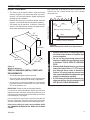
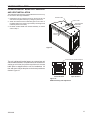
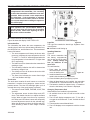
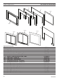
ICFDV Series Direct Vent
Gas Fireplace Insert
Models:
ICFDV30LNTSC, ICFDV30CNTSC
WARNING
IF The INFORMATION IN TheSe INSTRuCTIONS IS NOT
FOLLOWeD exACTLy, A FIRe OR expLOSION MAy
ReSuLT CAuSING pROpeRTy DAMAGe, peRSONAL
INjuRy OR LOSS OF LIFe.
–
–
Do not store or use gasoline or other flammable
vapors and liquids in the vicinity of this or any other
appliance.
WhAT TO DO IF yOu SMeLL GAS
• Do not try to light any appliance.
• Do not touch any electrical switch; do not use any
phone in your building.
• Immediately call your gas supplier from a neighbor's
phone. Follow the gas supplier's instructions.
• If you cannot reach your gas supplier, call the fire
department.
–
Installation and service must be performed
by a qualified installer, service agency or the
gas supplier.
WARNING: Improper installation, adjustment, alteration,
services or maintenance can cause injury or property
damage. Refer to this manual. For assistance or additional
information consult a qualified installer, service agency
or the gas supplier.
This appliance may be installed in an aftermarket*,
permanently located, manufactured home (uSA only) or
mobile home, where not prohibited by local codes.
This appliance is only for use with the type of gas
indicated on the rating plate. This appliance is not
convertible for use with other gases, unless a certified
kit is used.
* Aftermarket: Completion of sale, not for purpose of resale, from the
manufacturer.
Installation and
Operating Instructions
4164
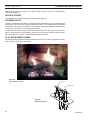
ICFDV insert cover
Due TO hIGh TeMpeRATuReS, The AppLIANCe
ShOuLD Be LOCATeD OuT OF TRAFFIC AND
AWAy FROM FuRNITuRe AND DRApeRIeS.
ChILDReN AND ADuLTS ShOuLD Be ALeRTeD
TO T h e h A Z A R D S O F h I G h S u R FA C e
TeMpeRATuRe AND ShOuLD STAy AWAy TO
AVOID BuRNS OR CLOThING IGNITION.
yOuNG ChILDReN ShOuLD Be SupeRVISeD
WheN They ARe IN The SAMe ROOM AS The
AppLIANCe.
CLOThING OR OTheR FLAMMABLe MATeRIAL
ShOuLD NOT Be pLACeD ON OR NeAR The
AppLIANCe.
Keep The ROOM AReA CLeAR AND FRee FROM
COMBuSTIBLe MATeRIALS, GASOLINe, AND
OTheR FLAMMABLe VApORS AND LIquIDS.
INSTALLeR: Leave this manual with the appliance.
CONSuMeR: Retain this manual for future reference.
20304164 10/11 Rev. 1
CONTeNTS
ICFDV Fireplace Insert
Thank you and congratulations on your purchase of a
Monessen Fireplace Insert
pLeASe ReAD The INSTALLATION AND OpeRATION INSTRuCTIONS BeFORe uSING The AppLIANCe!
IMpORTANT: Read all instructions and warnings carefully before starting installation.
Failure to follow these instructions may result in a possible fire hazard and will void the warranty.
Important Safety Information ......................................3
Code Approval ..............................................................4
product Features
High Elevations ........................................................5
Gas Pressures .........................................................5
Gas Specifications ...................................................5
Insert Dimensions ........................................................6
Installation Information ................................................7
Before You Start .......................................................7
Insert Applications ....................................................7
Clearances ...............................................................7
Clearances ....................................................................8
Insert Clearances .....................................................8
Mantel Clearances ...................................................8
Hearth Requirements ...............................................8
Operating Instructions ...............................................24
For Your Safety Read Before Lighting ...................24
Operating Instructions ............................................25
To Turn Off Gas ......................................................25
Signature Command System Operation...................26
Touch Screen Remote Control Operation ..............29
Air Shutter Adjustment ..............................................35
Glass Frame Removal ................................................36
Blower Removal and Assembly ................................37
Cleaning and Maintenance ........................................38
Venting System ......................................................38
Cleaning Glass .......................................................38
Pilot and Burner Flames ........................................38
Firebox Cleaning ....................................................39
Yearly Service Procedure.......................................40
Installation.....................................................................9
Insert Placement ......................................................9
Zero-Clearance Fireplace Requirements .................9
Troubleshooting .........................................................41
Venting Installation.....................................................10
Installation Precautions ..........................................10
Venting Requirements ............................................10
Altitude Considerations ..........................................11
Venting Configurations ...........................................12
Intake/Exhaust Manifold Removal & Vent ..................
Installation ..............................................................13
For Massachusetts Residents ONLy ........................46
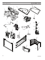
Replacement parts .....................................................42
Optional Accessories .............................................44
Warranty ......................................................................47
efficiencies..................................................................48
Insert Installation ........................................................14
Check Gas Type.....................................................14
Install Gas to Insert Location .................................14
Installation Items Needed ......................................14
Check Gas pressure...................................................16
electrical Installation..................................................17
Electrical Wiring .....................................................17
Log placement ............................................................18
Surround Installation .................................................22
2
20304164
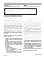
IMpORTANT SAFeTy INFORMATION
INSTALLeR
WARNING
Please leave these instructions with the appliance.
ICFDV Fireplace Insert
OWNeR
Please retain these instructions for future reference.
• Read this owner’s manual carefully and completely before trying to assemble, operate,
or service this fireplace.
• Any change to this fireplace or its controls can be dangerous.
• Improper installation or use of this fireplace can cause serious injury or death from
fire, burns, explosions, electrical shock and carbon monoxide poisoning.
This fireplace is a vented product. This fireplace must be
properly installed by a qualified service person. The glass
door must be properly seated and sealed. If this unit is not
properly installed by a qualified service person with glass
door properly seated and sealed, combustion leakage can
occur.
CARBON MONOxIDe pOISONING: Early signs of carbon
monoxide poisoning are similar to the flu with headaches,
dizziness and/or nausea. If you have these signs, the fireplace may not have been installed properly. Get fresh air
at once! Have the fireplace inspected and serviced by a
qualified service person. Some people are more affected
by carbon monoxide than others. These include pregnant
women, people with heart or lung disease or anemia,
those under the influence of alcohol, and those at high
altitudes.
Propane/LP gas and natural gas are both odorless. An
odor-making agent is added to each of these gases. The
odor helps you detect a gas leak. However, the odor added
to these gases can fade. Gas may be present even though
no odor exists.
Make certain you read and understand all warnings. Keep
this manual for reference. It is your guide to safe and proper
operation of this fireplace.
1. This appliance is only for use with the type of gas
indicated on the rating plate. This appliance is not
convertible for use with other gases unless a certified
kit is used.
2. For propane/LP fireplace, do not place propane/LP
supply tank(s) inside any structure. Locate propane/LP
supply tank(s) outdoors. To prevent performance problems, do not use propane/LP fuel tank of less than 100
lbs. capacity.
3. If you smell gas
• shut off gas supply.
• do not try to light any appliance.
• do not touch any electrical switch; do not use any
phone in your building .
• immediately call your gas supplier from a neighbor’s
phone. Follow the gas supplier’s instructions.
20304164
4.
5.
6.
7.
8.
9.
10.
11.
12.
13.
Never install the fireplace
• in a recreational vehicle
• where curtains, furniture, clothing, or other flammable objects are less than 36" from the front, top,
or sides of the fireplace
• in high traffic areas
• in windy or drafty areas
This fireplace reaches high temperatures. Keep children
and adults away from hot surfaces to avoid burns or
clothing ignition. Fireplace will remain hot for a time after
shutdown. Allow surfaces to cool before touching.
Carefully supervise young children when they are in
the room with fireplace.
Do not modify fireplace under any circumstances. Any
parts removed for servicing must be replaced prior to
operating fireplace.
Turn fireplace off and let cool before servicing, installing, or repairing. Only a qualified service person should
install, service, or repair the fireplace. Have burner
system inspected annually by a qualified service
person.
You must keep control compartments, burners, and
circulating air passages clean. More frequent cleaning
may be needed due to excessive lint and dust. Turn off
the gas valve and pilot light before cleaning fireplace.
Have venting system inspected annually by a qualified
service person. If needed, have venting system cleaned
or repaired. Refer to Cleaning and Maintenance, Page
38.
Keep the area around your fireplace clear of combustible materials, gasoline, and other flammable vapor and
liquids. Do not run fireplace where these are used or
stored. Do not place items such as clothing or decorations on or around fireplace.
Do not use this fireplace to cook food or burn paper or
other objects.
Never place anything on top of fireplace.
Continued on page 4
3
IMpORTANT SAFeTy INFORMATION & CODe AppROVAL
Continued from page 3
14. Do not use any solid fuels (wood, coal, paper, cardboard, etc.) in this fireplace. Use only the gas type
indicated on rating plate.
15. This appliance, when installed, must be electrically
grounded in accordance with local codes or in the
absence of local codes, with the National Electrical
Code, ANSI/NFPA 70, or the Canadian Electrical Code,
CSA C22.1.
16. Do not obstruct the flow of combustion and ventilation
air in any way. Provide adequate clearances around
air openings into the combustion chamber along with
adequate accessibility clearance for servicing and
proper operation.
17. Do not use fireplace if any part has been exposed to
or has been under water. Immediately call a qualified
service technician to inspect the appliance and replace
any part of the control system and any gas control
which as been submerged in water.
18. Do not operate fireplace if any log is broken.
19. Do not use a blower insert, heat exchanger insert, or
any other accessory not approved for use with this
fireplace.
20. Do not operate the fireplace with glass door removed,
cracked, or broken.
CODe AppROVAL
Direct Vent type appliances draw all combustion air from
outside of the dwelling through the vent pipe.
IMpORTANT:
pLeASe ReAD The FOLLOWING
CAReFuLLy
It is normal for fireplaces fabricated of steel
to give off some expansion and/or contraction
noises during the start up or cool down cycle.
Similar noises are found with your furnace heat
exchanger or car engine.
IMpORTANT:
pLeASe ReAD The FOLLOWING
CAReFuLLy
It is not unusual for gas fireplaces to give off some
odor the first time it is burned. This is due to the
manufacturing process.
please ensure that your room is well ventilated
during burn off — open all windows.
It is recommended that you burn your fireplace
for at least ten (10) hours the first time you use it.
Place the fan switch in the “OFF” position during
this time.
WARNING
ICFDV Fireplace Insert
Never connect unit to private (non-utility)
gas wells. This gas is commonly known as
wellhead gas.
These appliances have been tested by CSA and found to
comply with the established standards for DIRECT VENT
GAS FIREPLACE HEATERS in the USA and Canada as
follows:
LISTeD VeNTeD GAS FIRepLACe heATeR
TESTED TO:
ANSI Z21.88-2009/CSA 2.33-2009 STANDARDS
A manufactured home (USA only) or mobile home OEM
installation must conform with the Manufactured Home
Construction and Safety Standard, Title 24 CFR, part
3280, or when such a standard is not applicable, the
Standard for Manufactured home Installations, ANSI/
NCSBCS A225.1, or Standard for Gas equipped Recreational Vehicles and Mobile housing, CSA Z240.4.
!
WARNING
HOT GLASS WILL
CAUSE BURNS.
DO NOT TOUCH GLASS
UNTIL COOLED.
NEVER ALLOW CHILDREN
TO TOUCH GLASS.
4
20304164
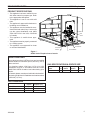
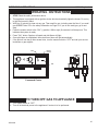
pRODuCT FeATuReS
ICFDV Fireplace Insert
pRODuCT SpeCIFICATIONS
• This appliance has been certified for use
•
•
•
•
•
•
with either natural or propane gas. Refer
to the appropriate data plates.
This appliance is not for use with solid
fuels.
The appliance is approved for bedroom or
bedsitting room installations.
The appliance must be installed in accordance with local codes if any. If none exist
use the current installation code. ANSI
Z223.1/NFPA 54 in the USA, CSA B149
in Canada.
This appliance is mobile home approved.
The appliance must be properly connected
to a venting system.
The appliance is not approved for closet
or recessed installations.
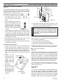
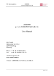
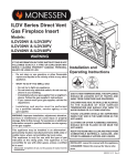
Gas
Valve
FP2946
Command
Center
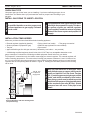
Figure 1 ICFDV Series Fireplace Insert Controls
hIGh eLeVATIONS
Input ratings are shown in BTU per hour and are certified
without deration for elevations up to 4,500 feet (1,370 m)
above sea level.
For elevations above 4,500 feet (1,370 m) in USA,
installation must be in accordance with the current
ANSI Z223.1/NFPA 54 and/or local codes having jurisdiction.
AC Module
Control Board
FP2946
ICFDV insert controls
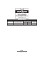
GAS SpeCIFICATIONS & ORIFICe SIZe
Model
Fuel
ICFDV30LNTSC Nat.
Max.Input Min. Input
BTu/h
BTu/h
31,000
22,500
Orifice
Size
#36
In Canada, please consult provincial and/or local authorities having jurisdiction for installation at elevations above
4,500 feet (1,370 m).
GAS pReSSuReS
Inlet Minimum
Inlet Maximum
Manifold Pressure
20304164
Natural
4.5” w.c.
10.5” w.c.
3.5” w.c.
Propane (LP)
11.0” w.c.
13.0” w.c.
10.0” w.c.
5
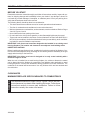
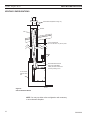
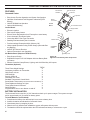
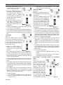
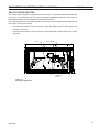
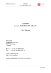
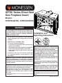
INSeRT DIMeNSIONS
ICFDV Fireplace Insert
26QE”
( 56 m m )
2256QE” ( 560 m m )
1156QE”
( 303 m m )
1056”
( 257 m m )
556QE”
( 144 m m )
2156QE"
( 535 m m )
1656"
( 410 m m )
246QE” ( 621 m m )
2756” ( 689 m m )
256M”
( 57 m m )
Figure 2
ICFDV Fireplace Insert Dimensions
4164
ICFDV in sert d im s
6
20304164
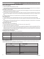
GeNeRAL INSTALLATION INFORMATION
ICFDV Fireplace Insert
BeFORe yOu START
Read this homeowner manual thoroughly and follow all instructions carefully. Inspect all contents for shipping damage and immediately inform your dealer if any damage is found. Do
not install any unit with damaged, incomplete, or substitute parts. Check your packing list to
verify that all listed parts have been received.
The following factors should be taken into consideration:
• This insert should have sufficient access for its safe operation and maintenance.
• The flow of combustion and ventilation air must not be obstructed.
• Minimum clearances to combustibles, such as mantels, must be maintained. Refer to Pages
8 and 9, Figures 3 and 4.
• Never obstruct the front opening of the insert.
• Do not install in the vicinity where gasoline or other flammable liquids may be stored.
• These units can be installed in a bedroom. Refer to National Fuel Gas Code ANSI Z233.1/
NFPA 54 (current edition), the Uniform Mechanical Code (current edition), and Local Building Codes for specific installation requirements.
IMpORTANT: your direct vent insert was designed to be installed in an existing wood
burning fireplace. The location and clearances are subject to local building codes.
INSeRT AppLICATIONS
Before installing the gas fireplace insert, consider the functioning needs of the fireplace. Confirm the size of the fireplace cavity, the design of the chimney, and the availability of the gas
supply and electricity for the insert fan.
IMpORTANT: your direct vent insert is designed to be only vented vertically with a
minimum height of 10 feet.
When the unit is installed into a wood burning fireplace, the minimum distance the mantel
can be placed above the fireplace is governed by local building codes applicable to wood
burning fireplaces. Consult local authorities having jurisdiction for these clearances. The
underside of the mantel will become warm. Use only finishes which are heat resistant and
do not discolor.
WARNING
CLeARANCeS
MINIMuM FIRepLACe SIZe/CLeARANCeS TO COMBuSTIBLeS
The dimensions shown on Pages 8 and 9, Figures 3 and 4, are minimum clearances to maintain when installing this heater. Follow these
instructions carefully to ensure safe installation. Failure to follow
instructions exactly can create a fire hazard.
20304164
7
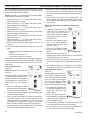
CLeARANCeS
ICFDV Fireplace Insert
INSeRT CLeARANCeS
No combustibles (ie: drapes, doors) may be within, or swing within 36" of the front of the insert.
Co
To
p
mb
us
Fa
tib
le
cin
Ma
nte
l
12” (305 mm)
Maximum Depth
Side Facing
g
Side Wall
12”
(305 mm)
9”
(228 mm)
3/4” (19 mm)
Maximum Depth
Combustible Facing
NOTe: Side clearance
to combustibles is 10"
(254 mm) from opening
whether it is side wall or
mantel legs.
10” (254 mm)
Minimum
12” (305 mm)
Minimum
Figure 3
Mantel Clearances
42” (1067 mm)
Minimum
FP2959
MANTeL CLeARANCeS
NOTe: The combustible area above the facing must not protrude more than 3/4" from the
facing. If it does, it is considered a mantel and must meet the mantel requirements listed
in this manual.
FP1947
insert clearances
9/08
The insert must be installed on a noncombustible
hearth extending a minimum of 12" from the
heARTh RequIReMeNTS
fireplace opening (local codes may require a larger hearth). The hearth must also extend to both
sides of the face.
8
20304164
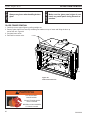
INSTALLATION
ICFDV Fireplace Insert
INSeRT pLACeMeNT
• The insert must be placed within a code-conforming
masonry fireplace or a tested and listed zero-clearance (UL-127, solid fuel) fireplace. Repair any fireplace
damage prior to installation.
Burn your insert for at least six (6) hours on "HIGH" the
first time you use it. Place the fan in the "OFF" position
during this time.
Insulation
• Because the insert uses a circulation blower, clean the
fireplace, smoke shelf and chimney before installing.
Sm
oke
Screen
23”
( 584 m m )
Masonry Lining or Refractory
r
pe
m
Da
al
rn
te es
In affl
B
aware of the large amount of heat this appliance produces when determining a location.
Metal or Glass Doors
• This heater may be placed in a bedroom. Please be
Shelf
Grate
Masonry Lining or Refractory
Figure 5 Metal Fireplace Zero-Clearance Requirements
21”
( 533 m m )
17”
( 432 m m )
Figure 4 Minimum Openings
f p 2945(MeTAL) FIRepLACe
ZeRO-CLeARANCe
FIR E B O X DIM S
RequIReMeNTS
• The damper and grate must be removed.
• The smoke shelf, internal baffles, screen, refractory and
metal or glass doors may be removed (if applicable).
• Do not remove or alter the insulation or any structured
rigid frame members (metal sides, floor, door frames,
face of the fireplace, etc.).
WARNING
30”
( 762 m m )
&P
ZEROCLEARANCEREQUIREMENTS
• Installer must
attach red warning plate to
the inside of the firebox of fireplace with
screws supplied.
• Do not cut any sheet metal parts of the
fireplace in which this gas fireplace insert
is installed. ThIS IS STRICTLy pROhIBITeD!
• If factory-built fireplace has no gas access
hole(s) provided, drill a 1.5" (37.5 mm) or
less through lower sides or bottom of
firebox. you must plug the access hole
with noncombustible insulation after gas
supply line has been installed.
• If your factory-built fireplace has air passages on the face for zero clearance, DO
NOT BLOCK TheSe pASSAGeS!
IMpORTANT: Please review the following carefully.
It is normal for inserts fabricated of steel to give off some
expansion and/or contraction noises during the start up or
cool down cycle. Similar noises are found with your furnace
heat exchanger or car engine.
It is not unusual for your insert to give off some odor the
first time it is burned. This is due to the curing of the paint
and any undetected oil from the manufacturing process.
please ensure that your room is well ventilated. OpeN
ALL WINDOWS DuRING INITIAL BuRN OFF/CuRING
phASe.
20304164
9
VeNTING INSTALLATION
NOTICe
Read all instructions completely and
thoroughly before attempting installation.
Failure to do so could result in serious injury,
property damage or loss of life. Operation of
improperly installed and maintained venting
system could result in serious injury,
property damage or loss of life.
Failure to follow these instructions will void
the warranty.
INSTALLATION pReCAuTIONS
Consult local building codes before beginning the installation. The installer must make sure to select the proper vent
system for installation. Before installing vent kit, the installer
must read this insert manual and vent kit instructions.
Only a qualified installer/service person should install venting system. The installer must follow these safety rules:
VeNTING RequIReMeNTS
WARNING
WARNING
ICFDV Fireplace Insert
• Make sure the exhaust pipe on heater
connects to exhaust portion of cap. Attach flex liners. Figure 6
• Do not crimp or rupture liner when bending it into chimney offsets.
• The exhaust vent must reline the entire length of chim•
•
ney and terminate above chimney top.
Vent must meet all vent manufacturer's requirements
when installed.
Make sure you have the following before installing
unit:
• 3" and 3" UL 1777 Listed gas liner for air inlet and
exhaust.
• Vertical Terminations kits:
H E D V 3 2 T 8 1 2 , H E D V 3 2 T 1 2 1 2 , H E D V R T,
A131AK33A
• Wear gloves and safety glasses for protection.
• Use extreme caution when using ladders or when
•
on rooftops.
Be aware of electrical wiring locations in walls and
ceiling.
The following actions will void the warranty on your venting system:
Inlet
Exhaust
• Installation of any damaged venting component.
• Unauthorized modification of the venting system.
• Installation of any component part not manufactured
or approved by MHSC.
• Installation other than permitted by these instruc-
WARNING
tions.
Maximum Height 40'
(12.9 m)
Minimum Height 10'
(3 m)
This insert must be vented to the outside.
The venting system must NeVeR be
attached to a chimney serving a separate
solid fuel burning appliance. each gas
appliance must use a separate vent system.
Do not use common vent systems.
Figure 6 Venting Unit
10
FP2947
FP2947
vent requirements
20304164
VeNTING INSTALLATION
ICFDV Fireplace Insert
ALTITuDe CONSIDeRATIONS
WARNING
This heater has been tested at altitudes ranging from sea level to 4,500 feet (1,370 m). In this
testing, heater with standard orifice burns correctly with just an air shutter adjustment. If you need
to resize orifice for use at high altitude, contact your dealer.
Failure to adjust air shutter properly may lead to improper combustion which can create a safety hazard. Consult your dealer or
installer if you suspect an improperly adjusted air shutter.
Termination Kit
(Refer to Page 10)
H ig h T em p
S il icon e
FP2948
Apply high-temperature silicone to
lines on both ends and secure with
two (2) screws
3" and 3" UL 1777 Gas
Liner
Figure 7 Connecting Vent Pipe to Heater
FP 2948
ex h au st p ip e
20304164
11
VeNTING INSTALLATION
ICFDV Fireplace Insert
VeNTING CONFIGuRATIONS
Termination Kits (Refer to Page 12)
Exhaust
Inlet
3" (75 mm) Exhaust
UL 1777 Gas Liner 3" (75 mm) Inlet
Recommended block-off
plate (noncombustible
metal). Prevents odors from
chimney entering room.
UL 127 Solid
Fuel Z.C Firebox
FP1924
Figure 8 Inlet and Exhaust Reline
FP2949
NOTe: You may use either reline configuration with a masonry
inlet exhaust reline
or zero-clearance fireplace.
12
20304164
VeNTING INSTALLATION
ICFDV Fireplace Insert
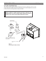
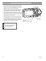
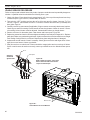
INTAKe/exhAuST MANIFOLD ReMOVAL
AND VeNT INSTALLATION
The intake/exhaust manifold is shipped attached to insert. It may
be removed to allow tight installation.
Exhaust Collar
1. Unfasten the two (2) machine screws on the face of the unit
and release the plate assembly by sliding the plate back.
2. Attach the exhaust and the intake flex pipes to the collar on
the plates with a hose clamp (not provided) or other approved
methods (check local codes).
3. Re-attach exhaust baffle and manifold assembly in reverse
order of Step 1.
Intake Collar
Exhaust/Intake
Slide Plate
Assembly
Machine
Screws
Figure 9
FP2979
intake exhaust
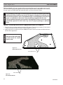
Loosen Four (4) Screws to Adjust
FP1961
The unit is shipped from the factory as a natural gas unit
with the baffle installed. The baffle should be sufficient for
venting up to 20 feet (6 m) off the top of the unit. An extra
baffle plate is shipped with the unit for installations 20
feet and above. Adjust the plate to the closed position as
desired. Figure 10
FP2979
Bottom View
Closed position
Bottom View
Open position
Figure 10 FP1961
Baffle Assembly and Adjustment
baffle adjustment
9/08
20304164
13
INSeRT INSTALLATION
ICFDV Fireplace Insert
CheCK GAS Type
Use proper gas type for the insert you are installing. If you have conflicting gas type, do not
install insert. See dealer where you purchased the insert for proper insert according to your
gas type.
A qualified installer or service person must
connect appliance to gas supply. Follow all
local codes.
CAuTION
WARNING
INSTALL GAS pIpING TO INSeRT LOCATION
For propane/Lp units, never connect insert
directly to the propane/Lp supply. This burner system requires an external regulator
(not supplied). Install the external regulator
between the burner system and propane/Lp
supply.
INSTALLATION ITeMS NeeDeD
Make sure you have the items listed below before installing appliance.
•
•
•
•
External regulator (supplied by installer)
• Piping (check local codes)
• Test gauge connection*
Sealant (resistant to propane/LP gas)
• Sediment trap (optional but recommended)
Tee joint
• Pipe wrench
approved flexible gas line with gas connector (if allowed by local codes — not provided)
* A CSA design-certified equipment shutoff valve with 1/8" NPT tap is an acceptable alternative to test
gauge connection. Purchase the CSA design-certified equipment shutoff valve from your dealer.
100 gal. (min.
Propane/LP
Supply Tank
External
Regulator
Vent
Pointing
Down
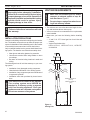
CAuTION
For propane/LP connections only, the installer must supply an external regulator. The external regulator will
reduce incoming gas pressure. You must reduce incoming gas pressure to between 11 and 13 inches of water. If you do not reduce incoming gas pressure, burner system regulator damage could occur. Install external
regulator with the vent pointing down as shown in Figure 11. Pointing the vent down protects it from freezing
rain or sleet.
use only new black iron or steel pipe. Internally tinned copper or copper tubing can be
used per National Fuel Gas Code, Section
2.6.3, providing gas meets hydrogen sulfide
limits, and where permitted by local codes.
Gas piping system must be sized to provide
minimum inlet pressure (listed on data plate)
at the maximum flow rate (BTu/hr). undue
pressure loss will occur if the pipe is too
small.
FP1930
Figure 11 External Regulator with Vent Pointing Down
(Propane/LP Only)
&0
EXTERNALREGULATOR
14
20304164
ICFDV Fireplace Insert
Only persons licensed to work with gas
piping may make the necessary gas connections to this appliance.
CAuTION
WARNING
INSeRT INSTALLATION
A manual shut-off valve is factory installed
upstream of the appliance. union tee and
plugged 1/8" NpT pressure tapping point
should be installed upstream of the appliance. Figure 12
NOTE : The gas line connection may be made using 1/2" rigid tubing or an approved
flex connector. Since some municipalities have additional local codes it is always best
to consult your local authorities and the current edition of the National Fuel Gas Code
ANSI.Z223.1, NFPA54. In Canada CSA-B149 (1 or 2) Installation Code.
A listed manual shutoff is factory installed upstream of appliance. Union tee and plugged 1/8"
NPT pressure tapping point should be installed upstream of the appliance. Figure 12
Check your building codes for any special requirements for
locating equipment shutoff valve to inserts.
Apply pipe joint sealant lightly to threads. This will prevent
excess sealant from going into pipe. Excess sealant in pipe
could result in clogged burner system valves.
CAuTION
IMpORTANT: The main gas valve is for turning on or shutting off the gas to the insert.
use pipe joint sealant that is resistant to
liquid petroleum (Lp) gas.
We recommend that you install a sediment trap/drip leg in
supply line as shown in Figure 12. Locate sediment trap/drip
leg where it is within reach for cleaning. Install in piping system between fuel supply and burner
system. Locate sediment trap/drip leg where trapped matter is not likely to freeze. A sediment
trap traps moisture and contaminants. This keeps them from going into the burner system
gas controls. If sediment trap/drip leg is not installed or is installed wrong, burner system may
not run properly.
Approved Flexible
Gas Line Supplied
with Appliance
Natural Gas
From Gas Meter
(4.5" w.c. to 10.5" w.c. Pressure)
propane/Lp
From External Regulator
(11" w.c. to 13" w.c. Pressure)
Tee Joint
Pipe Nipple
Figure 12 Gas Connection
20304164
Cap
3"
Mi
nim
um
FP1931
gas connection
9/08
15
CheCK GAS pReSSuRe
ICFDV Fireplace Insert
WARNING
1. Check gas type. The gas supply must be the same as
stated on the appliance’s rating decal. If the gas supply
is different from the fireplace, STOp! Do not install the
appliance. Contact your dealer immediately.
2. To ease installation, a 24" (610 mm) flex line with manual
shut-off valve has been provided with on this appliance.
Install and attach 1/2" gas line onto shut-off valve.
3. After completing gas line connection, purge air from
gas line and test all gas joints from the gas meter to
the fireplace for leaks. Use a solution of 50/50 water
and soap solution or a gas sniffer.
4. To check gas pressures at valve, turn captured screw
counter clockwise 2 or 3 turns and then place tubing
to pressure gauge over test point. Turn unit to high.
Figure 13. After taking pressure reading, be sure and
turn captured screw clockwise firmly to reseal. Do not
over torque. Check test points for gas leaks.
16
Do not use open flame to
check for gas leaks.
Pressure Inlet
Pressure Outlet
Pilot Adjustment Screw
Figure 13 Signature Command Valve
FP1909a
signature command valve
alternate view
8/08
20304164
eLeCTRICAL INSTALLATION
ICFDV Fireplace Insert
eLeCTRICAL WIRING
M ax
300 W at t s
This insert will work without any electrical supply.
Electricity is only needed to operate blower.
A / C M od u l e
T o O u t l et
Verify proper operation after servicing.
P il ot
M ax
300 W at t s
O p t ion al A u x .
300 W at t s
R F R eceiv er
O N / O FF B u t t on
A / C M od u l e
Con t rol B oard
B l ack / T h erm op il e
R ed / T h erm op il e
S en sor
Con v ersion
N G /L P
Ig n it or / S p ark er
Figure 14 Signature Command Wiring Diagram
P l u g - in Con n ect or
Con t rol B oard t o Com m an d Cen t er
CAuTION
NOTe: Wall switch
wires must be connected together.
Label all wires before
disconnecting when
servicing controls. Wiring errors can cause
improper and dangerous operation.
G rou n d
O FF/ L O
P l u g - in Con n ect or
S t ep p er M ot or t o
Con t rol B oard
L E D
O N /H I
M ast er S w it ch
Com m an d Cen t er
DC P ow er/ G reen
P l u g - in Con n ect or
Con t rol B oard t o
S ol en oid
G as O u t
G as In
P il ot G as T u bin g
WARNING
Val v e
electrical connections should only be performed by a qualified, licensed
electrician. Main power mustFP be
off when connecting to main electrical
2962
S
CS
w
irin g d iag
power supply or performing service.
Allramwiring shall be in compliance
with all local, city and state codes. The appliance, when installed, must be
electrically grounded in accordance with local codes, or in the absence
of local codes, with the National Electrical Code ANSI/NFPA 70 (latest
edition) and Canadian Electrical Code, CSA C22.1.
20304164
17
LOG pLACeMeNT
ICFDV Fireplace Insert
WARNING
Before you begin - This unit is supplied with six (6) ceramic fiber logs. Do not handle these logs with
your bare hands. Always wear gloves to prevent skin irritation from ceramic fibers. After handling
the logs, wash your hands gently with soap and water to remove any traces of fibers.
The positioning of the logs is critical to the safe and clean operation of this heater.
Sooting and other problems may result if the logs are not properly and firmly positioned in the appliance. Never add additional logs or embellishments such as pine
cones or vermiculite to the heater. Only use the logs supplied with the unit.
Failure to position the parts in accordance with diagrams below or to use only parts
specifically approved for this heater may result in property damage or personal
injury.
INSTALL LOGS AND ROCK WOOL (eMBeR MATeRIAL) IN FIReBOx
WARNING
1. Break up rock wool (ember material) into small fluffy pieces. Place evenly as shown. Do not exceed
1" layer covering all round burner ports. Refer to Figures 15 and 16.
2. Apply a light layer of embers to the ports. NOTe: Excessive amount of embers will affect the flame
and the flame appearance.
Do not use the entire bag
of rock wool to cover
burner area.
Figure 15 Ember Material Area
FP2961
Ember Material Area
Fp2961
ember material area
LG1116
Ember Material
Figure 16 Place Ember Material
18
LG1116
ICFDV ember material
20304164
LOG pLACeMeNT
ICFDV Fireplace Insert
Log #2
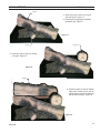
3. Align the two pin holes on Log #1
onto the burner. Figure 17
4. Place log #2 by aligning the holes to
the burner pin. Figure 17
Figure 17
LG1117
Log #3
Log #1
5. Position log #3 so that it is resting
on log #2. Figure 18
LG1117
ICFDV logs 1 2
Figure 18
Log #4
LG1118
6. Position log #4 so that the bottom
right end is resting on the pad on
log #3 and the left end is resting on
the flat spot on log #2. Figure 19
LG1118
ICFDV log 3
Figure 19
LG1119
19
20304164
LG1119
LOG pLACeMeNT
ICFDV Fireplace Insert
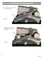
7. Align log #5 hole to the burner pin and
rest on log #2. Figure 20
Log #5
Figure 20
LG1120
8. Align the cutout on the bottom
of log #6 and fit it into log #5.
Figure 21
LG1120
ICFDV log 5
Log #6
Figure 21
LG1121
LG1121
ICFDV log 6
20
20304164
OpTIONAL GLASS & STONe INSTALLATION
ICFDV Fireplace Insert
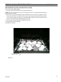
DeCORATIVe GLASS & STONe INSTALLATION
Use caution when handling glass.
1. Remove glass frame using the cam tool supplied with unit.
NOTe: The unit is designed to use 2/3 of the glass provided. The remaining decorative glass
is intended for future use.
2. Mix the two (2) bags of decorative glass provided in the kit as desired. Lay glass on top of
burner and cover burner area with one (1) layer. Glass may be used around the perimeter
next to the wall. Make sure glass is not blocking gaps between perimeter bracket and the
burner. Keep glass behind retaining flange. Figure 22
3. Place stones on glass randomly as desired. Figure 22
4. Replace glass frame assembly.
Installation is complete.
FP2960
Do not cover gap with
decorative glass
Figure 22
FP2960
stone glass
20304164
21
SuRROuND INSTALLATION
ICFDV Fireplace Insert
Insert
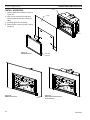
INSTALL SuRROuND
1. Remove glass door assembly. Page 36,
Figure 44
2. Align cast or beveled surround holes
with insert and attach with screws provided.
3. Re-attach glass door assembly.
4. Attach filigree to face by gently pushing
into place.
Facing
FP2950
Figure 23 Install Surround
Glass Door
Assembly
FP2950
install surround
Figure 24 Medium Surround
FP2951
Med surround 3 side
22
FP2951
Figure 25 Small Surround with Front
Control Access
FP2952
FP2952
Sm surround 3 side
20304164
SuRROuND INSTALLATION
Figure 26 Small Surround with Side
Control Access
FP2953
sm surr 3 side ctrl
20304164
ICFDV Fireplace Insert
FP2953
Figure 27 Trimmable Surround
FP2954
FP2954
contemporary surround
23
OpeRATING INSTRuCTIONS
ICFDV Fireplace Insert
WARNING
FOR yOuR SAFeTy ReAD BeFORe LIGhTING
If you do not follow these instructions
exactly, a fire or explosion may result
causing property damage, personal
injury or loss of lie.
A. This appliance is equipped with an ignition device which automatically lights the pilot. Refer
to the instructions.
B. BEFORE OPERATING smell all around the appliance area for gas. Be sure to smell next to
the floor because some gas is heavier than air and will settle on the floor.
WhAT TO DO IF yOu SMeLL GAS:
• Do not attempt to light any appliance.
• Do not touch any electric switch; do not use any phone in your building.
• Immediately call your gas supplier from a neighbor's phone. Follow the gas supplier's
instructions.
• If you cannot reach your gas supplier, call the fire department.
C. Use only your finger to push in the master switch. Never use tools. If the switch will not function by hand, do not try to repair it. Call a qualified service technician. Force or attempted
repair may result in a fire or explosion.
D. Do not use this appliance if any part of it has been under water. Immediately call a qualified
service technician to inspect the appliance and to replace any part of the control system and
any gas control that has been under water.
24
20304164
OpeRATING INSTRuCTIONS
ICFDV Fireplace Insert
OpeRATING INSTRuCTIONS
1. STOp! Read the safety information above.
2. This appliance is equipped with an ignition device which automatically lights the burner. Do not try
to light the burner by hand.
3. With five (5) minutes to clear out any gas. Then smell for gas, including near the floor. If you smell
gas, STOp! Follow "B" in the safety information on Page 24. If you do not smell gas, go to next
step.
4. Press the master switch to the "ON" (-) position. Within eight (8) seconds it will beep once. This
indicates the system is ready.
5. Press "ON " button. Sparker will spark and pilot flame will light.
6. Once pilot flame is established, the main burner flame will light automatically.
7. If the pilot will not stay lit after several tries, turn the master switch to "OFF" and call your service
technician or gas supplier.
OFF
OFF
ON
Master
Switch
ON
Command Center
FP1913
Switch box
8/08
&0
0ILOTWSPARKER
TO TuRN OFF GAS TO AppLIANCe
1. Turn master switch to "OFF".
2. Turn off all electrical power to the appliance if service is to be performed.
20304164
25
ICFDV Fireplace Insert
SIGNATuRe COMMAND SySTeM OpeRATION INSTRuCTIONS
FeATuReS
RF Receiver
ON/OFF
Command Center
• Easy Access Function Operation and System Configuration
• Operation Confirmation/Fault Diagnostic Indications (LED/
Buzzer)
• ON/OFF/HI/Med/Low Operation
• Optional Wall Mounting
Control Board
•
•
•
•
•
•
•
•
•
•
Electronic Ignition
Pilot Lockout safety feature
Electric Power Regeneration from Thermopile to save battery
6-hour Automatic Shut Down Option
Convenient NG/LP Gas Type Conversion
Standing Pilot/Intermittent pilot Conversion
Previous settings Restoration Ability (Memory Off)
Uninterrupted Operation During Power Outage (Automatic Battery Backup)
ON/OFF RF Remote Receiver
Optional Transmitter Learn Capability
To Sensor
To Sparker
NG/LP
Conversion
Control
Board
To Command Center
To Stepper Motor
To Valve
OFF
LED
ON
Master Switch
Command
Center
Battery Door
AC Module Board (Requires TSFSC Remote)
• Easy Snap-on Design
• Embedded Compact 120 VAC Adapter with Auto Battery Back
To Thermopile
Figure 28 Signature Command System Components
up Feature
• Remote Controlled 3-step Blower, Lighting, and On/Off Auxiliary AC Outputs
Transmitter (Optional)
TSFSC
Three Flame Height Settings
X
Low battery Indication for Transmitter
X
Child Proof Lock-out
X
LCD Backlight
X
Security Codes 16
X
Countdown 6 hr Timer
X
Standard Thermostatic Control Mode
X
Smart Mode® Thermostat (Auto Flame & Blower Modulation) X
Three Brightness Settings for Lights
X
Three Speed Control for Blower
X
On/Off Auxiliary
X
Programmable Timer to turn blower on and off
X
FP1917
Signature components
8/08
BATTeRy INSTALLATION
The Command Center uses four (4) "AA" batteries as back up for power outages. The system can operate for approximately six (6) months on battery power.
To Install Batteries (not included):
1. Press down the battery door tabs and pull out to remove battery door.
2. Install the batteries as indicated on Command Center.
3. Close battery door by snapping in place.
4. When the four (4) batteries are installed the system will operate without power.
5. The batteries should be replaced when the LED indicates low battery or at least once a year.
26
20304164
SIGNATuRe COMMAND SySTeM OpeRATION INSTRuCTIONS
ICFDV Fireplace Insert
SySTeM CONFIGuRATION/SeTup
All System configuration/setup is done on the Command Center.
NOTe: When using On/Off wall switch, the switch must be in the ON position to perform all configuration set
ups at the command center.
Intermittent/Standing pilot Setup (Default intermittent)
1. Holding the ON button on the Command Center while turning on the master switch will toggle between standing pilot and intermittent pilot.
2. After the above operation, one beep (for standing pilot) or two beeps (for intermittent pilot) will be given as
confirmation.
Six-hour Safety Shutdown Option (Default ON)
1. The system comes preset from the factory with a six (6) hour shutdown from its last command of operation.
This is done to prevent the fireplace from continuing to operate if unattended. You may disable this feature
if you wish.
NOTe: By disabling this feature, your fireplace may continue to operate unattended.
2. When the master switch is in the ON position (“-”), pressing the ON button and the OFF button on the Command Center simultaneously will toggle between enabling and disabling the six-hour shutdown option.
3. After the above operation, one beep (for enabling the six-hour shutdown option) or two beeps (for disabling
the six-hour shutdown option) will be given as confirmation.
Remote Transmitter Learn Function (Default OFF)
1. The RF receiver button located on the Control Board must be in the on position before the learn function can
begin. Use paper clip to depress button. One beep for RF receiver ON or two beeps for RF receiver OFF will
be given as confirmation.
2. After the RF receiver is on, holding the OFF button on the Command Center while turning on the master
switch will activate the learn function for the transmitter.
3. After the above operation, two beeps will be given and the green LED on the Command Center will flash for
10 seconds.
4. During the 10 seconds, press the OFF button on a transmitter to learn. Another two beeps will be given to
confirm a successful learning. Refer to transmitter instructions for remote operations.
Shutting Off the Standing pilot (Temporary Shut Off)
To shut off the standing pilot for service or summer shut down, press and hold the ON button on the Command
Center for 3 seconds when the master switch is in the ON position (“-”) and the main burner is off.
Note: Pilot will resume the next time system is turned on.
Key Combinations for System Settings
NOTe: When On/Off wall switch is used, it must be in the On position to perform all system setups.
Function
Intermittent/Standing
Pilot Setup
Standing Pilot Temp.
Shutoff
RF Remote Receiver
On/Off
Learn Remote
Transmitter
6-hour safety
shutdown setup
20304164
Operation
Hold the ON ▲ button while turning on the master switch
(Beep once for standing pilot, twice for intermittent pilot)
Hold the ON ▲ button 3 seconds (when the master switch
on the main burner is off)
Push the RF receiver On/Off button on the control board
Beep once for ON and beep twice for OFF
Hold the OFF ▼ button while turning on the master switch
(Beep twice then press any handheld remote button)
Press the ON ▲ button and OFF ▼ button simultaneously
(Beep once for ON, twice for OFF)
Default Setting
Intermittent
Pilot
RF OFF
ON
27
SIGNATuRe COMMAND SySTeM OpeRATION INSTRuCTIONS
ICFDV Fireplace Insert
FuNCTIONS/OpeRATION (with Command Center)
Turning on the fireplace
1. Turn on the master switch and wait for a beep.
2. Press the ON button on the Command Center or turn on wall switch. Pilot will light and burner will come on High setting or last memory setting (See Turning Off Fireplace below). For memory feature.
pilot Safety Lockout Function
1. If the pilot doesn’t light after sparking for 30 seconds, pilot trial lockout happens. The LED on the Command Center
flashes Green once every 2 seconds, until reset.
2. If the pilot flame is lost during normal operation, the system will try three (3) times to relight after three (3) failures,
flame loss lockout happens. The LED on the Command Center flashes Red-Green once every 2 seconds, until reset.
3. Turning the master switch on the Command Center to the off position, then ON again will reset the system.
Flame height Control
1. Press the ON button (on the Command Center) once to turn on the main burner with maximum flame height.
2. Press the OFF button to decrease flame height. The first two presses will decrease the flame height to medium and
low.
3. The third press on OFF will turn off the main burner. In standing pilot configuration, the pilot will stay; in intermittent
pilot configuration, the pilot will be shut off.
Turning the Fireplace Off
There are three ways to turn the fireplace off.
1. Flip the master switch to the off (“O”) position. (This will turn the entire system OFF.)
2. Press the OFF button to Medium, Low, then Off.
3. Hold the OFF button anytime for three seconds or by turning off the wall switch. These two commands of OFF are
(Memory Off) the system will remember all last settings before turning off. The next time the fireplace is turned on, all
settings will resume. To reset, change to the desired settings and shut off by using the Memory Off commands and
the system will be reset to those new settings.
Command Center Operations:
The following functions are available on the Command Center.
Function
Power Up
Fireplace ON
Fireplace OFF
Flame Height Up
Flame Height Down
Operation
Flip the master switch to the ON ("_") position to power up the system
Press the ON ▲ button on the Command Center or turn on wall switch to turn the fireplace on
Flip the master switch to the OFF ("o") position OR press the OFF ▼ button 3
times OR for Memory Off, hold the OFF ▼ button 3 seconds, or turn off wall switch
Press the ON ▲ button once to turn on the fireplace with maximum flame height
Press the OFF ▼ button to lower the flame height to Medium and Low
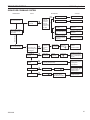
Self Diagnostics Chart:
The Command Center has a self-diagnostic LED enabling you to troubleshoot problems and potentially avoid a service call. Please refer to the charts below for indicator reference.
Fault
Conversion Cover Missing
Spark Fail
No Sensor Signal
Pilot Lockout - trial
Pilot Lockout - flame loss
Low Battery
No or Low Thermopile Power
Learning
AC Power On
Pressure Switch Failed (Power Vent only)
28
LeD Indication
One RED (1 time)
Two RED (1 time)
Three RED (1 time)
One GREEN, every 2 sec. (until manual reset)
One RED-GREEN, every 2 sec. (until manual reset)
One RED, every 10s (continuously)
Two RED, every 10s (continuously)
GREEN Flashes, every 1 sec. (for 10 sec.)
GREEN solid
One RED every 2 sec. (until manual reset)
20304164
WARNING
Information Bar
The information bar shows the room temperature, the
“sending signal” radio icon, the low battery indication icon,
the child-proof icon, and the flame icon. This area doesn’t
have touch buttons.
• The room temperature will always be shown after
•
•
•
•
power-up. It displays the room temperature from 40
°F to 99 °F. “Lo” and “HI” will be displayed when the
room temperature is lower than 40°F or higher than
99°F, respectively.
The radio icon will be shown when the transmitter is
sending a signal.
The low battery indication icon will be shown when
the battery voltage is low.
The child-proof icon will be shown when the childproof mode is activated.
The flame icon indicates the current flame height
- Off, Low, Medium and High
Touch Area
The touch area contains all touch buttons to control the
transmitter. It consists of two categories: menus and adjustment arrows. The blue LED backlight lights up for 8
seconds when any of the touch buttons is pressed.
Adjustment
Controls
Figure 29 shows the display of the TSFSC LCD.
Logo
Bar
n Function Areas of the LCD Display
Menus
Turn appliance OFF (at the Master Switch) if
you are away from your house for an extended
period of time. Never leave anything on top of
the surface of the transmitter.
Touch Area
Due to the sensitive temperature monitoring
components in the transmitter, it is necessary
to allow the transmitter to stabilize to room temperature before accurate room temperatures
are displayed. If the transmitter is activated
from a severe cold condition, allow 15 minutes
for accurate temperature readings to appear on
the LCD display.
ICFDV Fireplace Insert
Information
Bar
NOTe
TOuCh SCReeN ReMOTe CONTROL OpeRATION
Logo Bar
Function Areas of the LCD Display
Figure 29
The Logo Bar contains the brand logo: Signature Command System.
n Initialization and Setting up
FP2646
Installing Batteries:
TSFSC display
Figure 30
The remote transmitter has
two battery compartments,
one on each end of the transmitter. Always change all
four (4) batteries at the
same time.
Battery Door
Tabs
To install batteries,
1. Press down the battery
door tab and pull out to reFigure 30
move the battery door.
2. Install the batteries as indicated inside the battery compartments.
3. Close the battery door by snapping
in place.
FP2607
4. When all four batteries are installed,
the transmitter
install battery
will initialize for 5 seconds and then is ready for use.
5. The batteries should be replaced every 12 months or
when the low battery icon indicator is displayed.
• The menus include TIMER, THERMO, LIGHT, FAN
Changing Temperature unit
•
1. All available icons on the LCD will be turned on then
be cleared.
2. The LCD will display temperature unit: °F. Use ON ∆
to toggle the units between °F and °C within the first 5
seconds.
3. The transmitter enters Manual Mode
4. The LCD displays room temperature with the chosen
unit.
and AUX.
The adjustment arrows include ON/up and OFF/
down. Their default function is to adjust the flame
height. When a button from the menu is pressed,
the ON/up and OFF/down buttons will temporarily
become adjustment controls for the selected item.
When the adjustment is done, the ON/up and OFF/
down buttons go back to flame height controller
again.
20304164
When batteries are installed in the transmitter,
29
ICFDV Fireplace Insert
TOuCh SCReeN ReMOTe CONTROL OpeRATION
Battery Door
Setting privacy Code on Transmitter:
Figure 31
The remote transmitter privacy code is preset in factory.
In the event of activation or interference from other nearby transmissions, change the code using the following
procedures (learn function must be
performed after changing the code):
FP2650
WARNING
1. Press the ON/arrow button and
Master Switch
the TIMER button at the same
ON
time to enter privacy code setup
LED
mode.
Figure 33
OFF
Command Center
2. The setup display is shown in the
figure. The four digits on the top
4. During the 10 seconds, press the OFF button on the
stand for the privacy code (as the
transmitter to learn. Another two beeps will be given to
actual DIP switches on Ambient’s
FP2650
confirm a successful learning. Figure 33
previous remotes). The default
command ctr ctrl brd
values of the four digits will be all
Do not use two (2) or more remote control sysFigure 31
“1” (ON).
tems in the same area with the same privacy
3. The first digit will be flashing upon entering the setup
code setting, as they will communicate with
FP2649
mode. Push the ON button to toggle its
value between
each other. This may cause the appliances to
“0” (OFF) and “1”(ON), and push the
button
set“OFF”
privace
code
malfunction.
to jump to the next digit. The next digit will then start
flashing and the first one stops flashing. Set up the
Resetting the transmitter:
four digits to your choice.
If the transmitter is not working properly, reinstall the bat4. After setting up all the four digits, push “OFF” to finish
teries to reset the transmitter.
the process and return to the previous mode.
1. Pull out at least one of the batteries.
5. The Signature Command control board then needs to
2. Press any key on the screen to discharge.
re-learn the new setting.
3. Wait for 10 seconds and reinstall the batteries.
performing Learn Function
1. The RF receiver button on the control board in the
fireplace must be in the on position before the learn
function can begin. Figure 32 With the Command Center master switch in the ON position, use paper clip to
depress the recessed button on Control Board, one
beep for RF receiver ON or two beeps for RF receiver
OFF.
2. Holding the OFF
RF Receiver
button on the ComON/OFF
mand Center while
turning
on
the
master switch will
activate the learn
function for the
transmitter.
3. After the above operation, two beeps
will be given and
the green LED on
the Command CenControl Board
ter will flash for 10
seconds.
Figure 32
30
Pushing and holding any key for more than 10 seconds
until the display refreshes will also reset the transmitter.
n Functions and Operations
General:
The TSFSC Remote Control has four (4) operating modes:
Manual, Timer, Thermostatic and Smart Mode® thermostat. The control system can be set to temperature range
between 45° F and 90° F. The blower speed and flame
height can be adjusted in the manual, timer and thermostatic mode. The Smart Mode® thermostat will automatically adjust flame height and blower speed according to
the difference between Set and Room temperatures.
The transmitter will operate the remote receiver from 1
foot to a maximum of 30 feet. The distance is reduced
when batteries are low.
Manual Mode
Figure 34
In this mode, the TIMER button and the THERMO button will only display “TIMER” and “THERMO”, respectively without showing the time and the SET temperature.
Pressing the ON/up and OFF/down buttons will change
FP2650
the flame height if none of the menu buttons (TIMER,
THERMO,
FAN, AUX) are pressed and flashing.
command
ctrLIGHT,
ctrl brd
20304164
TOuCh SCReeN ReMOTe CONTROL OpeRATION
1. Press the ON/up button to turn
on the fireplace. The flame icon
on the LCD displays High.
2. Press the OFF/down button to
decrease the flame height and
turn off the fireplace. When the
OFF/down button is pressed
for three times, the flame icon
changes form High to Medium,
to Low, then to Off.
3. If the OFF button is held for
more than 3 seconds at any
flame height, the fireplace will
be turned off and the flame icon
disappears.
Figure 34
4. Sliding up and down on the arrowFP2651
buttons can also
turn on or turn off the fireplace.
Manual mode
5. If the fireplace is shut off using the above methods in 3
and 4, all the settings will be remembered and will be
resumed next time the fireplace is turned on (Memory
Off).
Timer Mode
Figure 35
Press the TIMER button to enter
timer mode. The fireplace will stay
on for a period of time as specified
by the timer and then be shut off
by the transmitter when the timer
counts down to zero.
1. When the TIMER button is
pressed, the Set Time appears
in the frame of the button and
flashes.
2. Use ON/up and OFF/down to
Figure 35
increase or decrease the Set Time in 15 min. increFP2652
ments, between 0:00 to 6:00. Sliding up and down on
mode
the arrow buttons will increase or Timer
decrease
the Set
Time in 1 hour increments.
3. Push the TIMER button again to confirm the Set Time,
the transmitter sends an ON signal to turn on the fireplace.
4. The flashing stops and the ON/up and OFF/down buttons become flame height controller again. The flame
height will then stay as set up by the ON/up and OFF/
down buttons.
5. The TIMER button can be used when the transmitter is in Manual Mode or in Thermostat Mode. In both
modes, the fireplace will be shut down completely
when the timer counts down to zero.
6. To exit Timer Mode,
a. Push and hold the TIMER button for 3 seconds Or
b. Use the OFF/down buttons to decrease the Set
Time to zero Or
20304164
ICFDV Fireplace Insert
c. Slide down on the arrow buttons to exit TIMER
mode and shut off the fireplace.
Thermostat Mode
Figure 36
NOTe: The Command Center buttons will disable when thermostat is
being used.
Press the THERMO button to set
the transmitter in thermostat mode.
The transmitter will automatically
turn on the fireplace when the
room temperature is below the set
temperature and turn off the appliance when the room temperature
is above the set temperature within
one degree.
Figure 36
1. When the THERMO button is pressed,FP2653
the Set temperature appears in the frame of the button and flashes.
thermo mode
2. Use ON/up and OFF/down to increase or decrease
the Set temperature in 1 degree increments, between
45 degrees and 90 degrees. Slide up and down on the
arrow buttons will increase or decrease the Set Temperature in 10 degrees increments.
3. Press the THERMO button again to confirm the Set
Temperature. The transmitter will send out an On
signal or an Off signal depending on the relationship
between the Set temperature and the Room temperature.
4. The flashing stops and the ON/up and OFF/down buttons become flame height controller again. The flame
height will then stay as set up by the ON/up and OFF/
down buttons.
5. To exit Thermostat Mode:
a. push and hold the THERMO buttons for 3 seconds or
b. slide down on the arrow buttons to exit Thermostat mode and shut off the fireplace.
Smart Mode® Thermostat Option for Thermostat
Mode
Figure 37
Press and hold the THERMO button and the ON/UP
button at the same time
for 3 seconds to toggle
between Smart Mode®
thermostat and the regular Thermostat Mode. The
icon “Smart Mode” will appear under the Set Temperature. The transmitter
will automatically adjust
the flame height according
to the difference between
Smart
Mode
Icon
FP2654
smart mode
Figure 37
31
ICFDV Fireplace Insert
TOuCh SCReeN ReMOTe CONTROL OpeRATION
the Set temperature and the Room temperature. There
is no manual flame height adjustment. The fan speed will
also automatically adjust if turned on.
NOTe: there will a 10 second delay for the flame adjustment when the fireplace is turned on.
1. When Set Temp. is 3° F or higher than Room Temp.,
flame height will be on High.
2. When Set Temp. is 2° F higher than Room Temp.,
flame height will be on Medium.
3. When Set Temp. is 1° F higher than Room Temp.,
flame height will be on Low.
4. When Set Temp. is equal to Room Temp., flame height
does not change (stays on low).
5. When Set Temp. is lower than Room Temp., the fireplace will be shut off.
6. When Set Temp. is 1° F higher than Room Temp.,
again the flame height will be on Low.
7. the fan speed follows the flame height, if the fan is
turned on.
To exit Smart Mode® thermostat and shut off the fireplace;
a. push and hold the THERMO buttons for 3 seconds, Or
b. press the OFF button, Or
c. slide down on the arrow buttons.
To shut off the Smart Mode® thermostat option and return
to regular thermostat mode, press and hold the THERMO
button and the ON/UP button at the same time for 3 seconds again.
Blower Speed Control
Figure 38
NOTe: Blower will only work with
flame on.
The blower speed control function
is used to adjust the speed of the
blower connected to the Signature
Command System. There are four
speed levels, Off, Low, Medium,
High.
1. Press the FAN button to enter
the blower speed control mode.
Figure 38
The fan icon will start flashing.
2. Press the ON/up and OFF/down button
to increase/deFP2655
crease the blower speed.
blower speed control
3. Press the fan button again to confirm the speed setting. If the fireplace is on, the blower speed will take
effect right away; if the fireplace is off, the receiver will
remember this setting and the blower is still off (see
blower On Delay and Off Delay in the next section).
4. After the signal is sent, the ON/up and OFF/down buttons become flame height controller again.
32
5. When the fan button is flashing, slide up and down on
the arrow buttons will turn the blower speed to High
or Off directly without pressing the fan button again to
confirm.
6. If the blower is turned on using the FAN button, the
blower speed will adjust automatically when using
Smart Mode® thermostat (See Smart Mode® thermostat section).
Blower On Delay Time and Off Delay Time Setup
Figure 39
1. Hold the FAN button for 3 seconds until two numbers appear on the LCD screen. The
left number is blower On Delay
and the right number is blower
Off Delay Time.
2. When the first number is flashing, use the ON/up button to
set the desired On Delay Time
from 0 to 15 min.
3. Press the OFF/down button
to jump to the Off Delay Time
setup.
Figure 39
4. When the second number is
FP2656
flashing, use the ON/up button again to set the desired
Off Delay Time from 0 to 15 min. blower delay setup
5. Press the OFF/down button again to finish the setup
and the new settings will be transmitted to the receiver.
6. The default settings are 5 minutes for the On Delay
Time and 8 minutes for the Off Delay Time, as shown.
Light Brightness Control
Figure 40
The light brightness control function is used to adjust the brightness of the light bulbs connected
to the AC module on the Signature Command System. There
are four light brightness levels
defined: Off, Low, Medium, High
1. Press the LIGHT button to enter the light brightness control
mode. The LIGHT icon will
start flashing.
2. Press the On/up and OFF/
down buttons to increase/deFigure 40
crease the light brightness
FP2657
(Off-Low-Medium-High).
Light
control
3. Press the light button again to confirm
thebright
setting.
The
new setting will be transmitted to the receiver.
4. After the signal is sent, the On/up and Off/down buttons become flame height controller again.
20304164
TOuCh SCReeN ReMOTe CONTROL OpeRATION
5. When the light button is flashing, slide up and down on
the arrow buttons will turn the light brightness to HIGH
or Off directly without pressing the light button again to
confirm
Aux Control (Optional)
The AUX control function is used to turn on or
turn off the auxiliary component connected to the
AC module of the Signature Command System.
Press the AUX button to turn on or turn off the
auxiliary.
1. When the auxiliary is turned on, the icon will become
solid text and the “ON” icon will appear below
the
FP2658
“AUX” icon.
AUX
2. When the auxiliary is turned off, the icon will become
hollow text and the “ON” icon will disappear.
NOTe: Some fireplaces use the AUX function to control
options within the fireplace. Refer to fireplace manual for
operation.
Setting up Blank Screen or Constant Display in Idle
Figure 41
There is an option to
set up how the LCD
displays and functions when the transmitter is in idle. There
are two choices:
1. A) Mode. When
the transmitter is
in idle, the icons
in the “touch area”
Figure 41
(timer, thermostat,
blower, light and AUX) will disappear, as shown in the
FP2659
figure on the left. When any
of the touch buttons is
pressed, those icons will appear
are ready to opblankand
screen
erate (default).
2. B) Mode. The transmitter always displays all available
icons showing current status of timer, thermostat,
blower, light and AUX as shown in the figure on the
right.
Press TIMER and THERMO buttons at the same time for
3 seconds to toggle between A) and B).
1. When the current setting is A), touch any place in the
touch area to bring up the icons then press TIMER button and THERMO button at the same time for 3 seconds. The backlight will flash once to indicate that the
setting has changed to B).
2. When the current setting is B), pressing TIMER button
and THERMO button at the same time for 3 seconds
will switch to A) Mode. The touch area icons will disappear.
20304164
ICFDV Fireplace Insert
n Safety Features
1. Low Battery Detection
When low battery condition occurs, the transmitter will
turn off the fireplace.
A) Battery voltage is checked every one minute. When the battery voltage is low, the
LCD displays a low battery icon which will
exist in all modes.
B) The transmitter will not operate with low
battery voltage. Change the batteries before
the
FP2612
batteries become too weak for normal operations.
low batter
2. Power On Initialization
After the power-on initialization, the transmitter sends
a signal to turn off the fireplace.
3. Thermal Shutdown
When the ambient temperature is more than 99°F, the
transmitter will turn off the fireplace.
A) The LCD will display “HI”.
B) The Transmitter will not function until the room temperature has dropped below 99 degree
Fahrenheit.
4. Low Temperature Condition
When the ambient temperature is less
than 40 degrees Fahrenheit, the LCD will
display “LO”, and NO SIGNAL will FP2613
be
sent to turn on the appliance.
HI
All functions still remain the same for
both Manual Mode and Thermostat
Mode
5. Child-proof Protection
The child-proof icon will be shown when
the child-proof mode is activated by
pressing the ON button and the OFF
button at the same time for three seconds.
A) Enter childproof mode by pressing and holding both
the ON button and the OFF buttonFP2614
simultaneously for 3 seconds. The Childproof indicator
will be
lo no child
shown on the LCD.
B) Deactivate childproof mode by pressing and holding the ON button and the OFF button simultaneously for 3 seconds again. The Childproof indicator
disappears on the LCD.
C) The transmitter cannot be operated in childproof
mode.
33
TOuCh SCReeN ReMOTe CONTROL OpeRATION
ICFDV Fireplace Insert
n using the Mounting Base
The transmitter comes with a mounting base which allows
you to hang the transmitter on the wall.
1. Secure the mounting base
on the wall with supplied
screws. For best viewing
angle, make it the same
height as your eyes.
2. Hang the transmitter on the
hook of the mounting base,
then push down so the
transmitter is flush to the
mounting base.
Figure 42
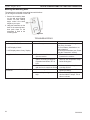
FP2674 TROUBLESHOOTING
mounting base
Symptom
1. Battery icon on LCD on transmitter
2. LCD display is blank
3. LCD display shows “funny” display
4. Appliance does not come on
5. Blower is not on after the fireplace is
turned on
34
Causes
1. Low Battery
Action
1. Replace batteries. Change batteries every 6 months.
2. Check battery installation or replace batteries.
3. Reset the transmitter (see “Reset
ting the Transmitter” section).
1. Make sure the transmitter has
learned to the receiver.
1. Move transmitter to a cooler place
and wait until temperature drops
below 99 degrees.
2. The transmitter did not match
with the receiver
3. Transmitter measures temperature exceeding 99 degrees
Fahrenheit and shows “HI” on
LCD
4. Distance between the transmitter 1. Make sure the opening distance is
and receiver is more than 30 feet
less than 30 feet.
5. Blower setting is off
1. Press FAN key to select Fan
speed you desire.
6. Blower delay setting is set too
1. Press and hold FAN key to set
high
desired ON/OFF delays. This is
done in minutes.
20304164
AIR ShuTTeR ADjuSTMeNT (NATuRAL GAS ONLy)
ICFDV Fireplace Insert
ADjuST The AIR ShuTTeR
The venturi under the burner is equipped with an air shutter. The opening of the venturi has been
set at 3/16" for Natural Gas and fully open for Propane installation at sea level. The burner on
Natural Gas models may be adjusted for high altitude as follows:
To access the air shutter, remove three (3) screws securing burner to engine base and slide burner
to the left or remove from firebox.
• To increase air mixture, loosen the screw to open the shutter more. This will reduce soot
formation. Figure 43
• To decrease air mixture, loosen the screw to close the shutter. Flames will be more yellow.
Figure 43
Burner
Pilot Assembly
Venturi
Air Shutter
Adjustment
Screw
FP2963
Figure 43 Air Shutter Adjustment
FP2963
venturi
20304164
35
GLASS FRAMe ReMOVAL
Always use gloves when handling broken
glass.
WARNING
CAuTION
ICFDV Fireplace Insert
Make sure the glass panel edges do not
touch any metal parts during thermal expansion.
GLASS FRAMe ReMOVAL
1. Carefully remove upper filigree by pulling straight out.
2. Remove glass frame from insert by releasing two latches on top of insert and lifting the door up
and off the unit. Figure 44
3. Set glass frame aside.
Latches
4. Re-install in reverse order.
FP2955
Figure 44 Glass Frame Removal
FP2955
install glass frame
!
WARNING
HOT GLASS WILL
CAUSE BURNS.
DO NOT TOUCH GLASS
UNTIL COOLED.
NEVER ALLOW CHILDREN
TO TOUCH GLASS.
36
20304164
BLOWeR ReMOVAL and ASSeMBLy
ICFDV Fireplace Insert
Turn off the unit and allow to cool completely. Turn off
gas at shut-off and disconnect all electricity to unit.
1. Remove the exhaust/intake plate assembly. Refer to
Page 13. Pull unit out of fireplace.
2. Unfasten two (2) plates on the rear of the unit.
3. Attach blowers to the plates.
4. Wire blower according to the wiring diagram.
5. Reinstall the plate onto the back of the unit.
6. Slide unit into fireplace. Reinstall exhaust/intake assembly.
CAuTION
BLOWeR RepLACeMeNT
Label all wires prior to disconnection when
servicing controls. Wiring errors can cause
improper and dangerous operation. Verify
proper operation after servicing.
FP2956
Figure 45 Blower Removal and Assembly
FP2956
install blowers
20304164
37
CLeANING and MAINTeNANCe
ICFDV Fireplace Insert
Make sure the gas valve knob is in the “OFF” position. Wait at least five (5) minutes before
start-ing maintenance.
VeNTING SySTeM
A qualified agency should examine the venting system annually.
CLeANING GLASS
Clean the ceramic glass periodically. Condensation will sometimes form on the glass during a
cold startup. This is normal for all gas fireplaces and inserts. This condensation often attracts
dust and lint to the surface of the glass. The initial paint curing of the appliance can also leave
a slight film on the glass. This is a temporary problem.
You should clean the glass after the first two weeks of use. After that, you should clean the
glass no more than two or three times a season. Use a mild glass cleaner to clean the door.
Do not use abrasive cleaners. They will damage the glass surface.
pILOT AND BuRNeR FLAMeS
Visually check pilot and burner flames periodically. Refer to Figure 46 for typical burner flame.
Refer to Figure 47 for typical pilot flame.
LG1122
Figure 46 Typical Burner Flame
Sensor
LG1122
ICFDV log flame
Thermopile
Figure 47 Typical Pilot Flame
FP2453
38
20304164
CLeANING and MAINTeNANCe
ICFDV Fireplace Insert
WARNING
FIReBOx CLeANING
• Allow logs to cool completely before cleaning. Logs reach high temperatures.
• Make sure clearances to combustibles leave enough room for maintenance and service.
• Carefully reassemble and reseal insert properly after any cleaning
or servicing.
1.
2.
3.
4.
5.
Carefully remove log set, and embers from combustion chamber.
Vacuum burner compartment thoroughly.
Vacuum any dust off logs.
Remove any lint from main burner and pilot.
Carefully replace log set, and embers in their correct positions. Refer to Pages 18 through
21.
6. Replace door.
7. Relight pilot. Refer to Page 25.
8. Turn on main burners.
20304164
39
MAINTeNANCe
ICFDV Fireplace Insert
yeARLy SeRVICe pROCeDuRe
Failure to inspect and maintain heater may lead to improper combustion and a potentially dangerous
situation. A qualified technician should do the following once a year.
1. Check pilot flame. Flame should touch approximately 3/8" of the top of thermopile and touch top
of thermocouple. Figure 38 If not, contact dealer for service.
2. Turn switch to “OFF” position and gas shut off to off to turn gas off to heater. See step “To Turn
Off Gas”, Page 25. Allow heater to cool for 15 minutes. Remove decorative face (if installed) and
door glass. Page 36
3. Carefully remove log setor stones (if applicable). If logs or stones are severely deteriorated, replace.
Check logs or stones for sooting. A small amount of soot along bottom of either is normal. If excessive sooting is found, heater must be adjusted. Contact dealer where you bought heater.
4. Remove rock wool or decorative glass. Clean burner and burner ports. Figure 48
5. Replace log set and rock wool or stones and glass according to instructions on Pages 18-21. Replace
glass door. Make sure gasket along perimeter of glass contacts face of firebox and forms an airtight
seal. Realign if airtight seal is not formed. Replace door glass and glass frame if damaged.
6. Inspect area around controls. Clean if necessary. Check gas control valve and all gas lines. If damaged, do not use heater. Contact your dealer.
7. Start pilot and turn on main burner. Flames should be orange/yellow and not touch top of firebox.
If pilot or main burners do not burn correctly, contact your dealer for service. Monitor blower operation.
Sensor
Signature
Command
System pilot
Thermopile
Figure 38 Before taking unit apart, check pilot
flame. Flame should touch thermocouple and thermopile.
FP2453
FP2453
hooded pilot flames
Burner Ports
FP2957
Figure 48 Check Burner Ports and Burners
40
Fp2956
burner ports
20304164
TROuBLeShOOTING
ICFDV Fireplace Insert
SIGNATuRe COMMAND SySTeM
OPERATION
Install batteries and/or
plug in the AC board
FAULT
No beep in about
8 seconds
A
Using
battery?
Make sure
Command
Center and
the control
board are
connected by
a 2 feet or 15
feet cable
After the beep
Flip the master switch
(rocker switch) to the
ON position
Press the ON button on
the Command Center
No beep
or
no sound from the
valve indicating pilot
solenoid open
B
No sparking on
the pilot
C
Sparking doesn’t
continue
D
Pilot doesn’t light
Main burner doesn’t
light
ACTION
DIAGNOSIS
E
F
Check NG/LP
conversion cap
and control
board
connections
Check pilot
connections
Battery polarity wrong?
Re-install batteries
Battery voltage low?
Change batteries
AC plug is plugged to
AC mains?
Plug the AC plug to
AC mains
The 5-pin connector on
the AC board broken or
bent?
Repair or replace the
AC Board
LED on the Command
Center does not show
solid green?
Replace the AC Board
Check valve
connections
Check
grounding
Check power
supply (go
through A )
Replace the Control
Board or
Command Center
Go through
B
Sparking is happening
elsewhere (under the
pilot), re-install/replace
the pilot
The Control Board is having interference from the
surrounding metal (Ground)
Check gas supply
Go through E
Go through C
The sensor on the pilot
is not in the flame
(pilot flame too small)?
Re-install the Control
Board, move it around
or change the
Control Board
Sparking is not in the
path of gas flow, adjust
sparker position or
replace the pilot
Adjust sensor position
or replace the pilot
FP1911
troubleshoot sc
8/08
20304164
41
RepLACeMeNT pARTS
ICFDV Fireplace Insert
16
3
15
5
18
17
4
2
6
1
20
19
21
25
22
26
24
29
17
27
26
23
28
36
33
34
37
32
38
31
35
42
20304164
4164
ICDV p art s
RepLACeMeNT pARTS
Description
qty.
Log #1
1
Log #2
1
Log #3
1
Log #4
1
Log #5
1
Log #6
1
Stone xx White
3
Stone xx Black
1
Stone xx Sand
2
Stone xx Dark Gray
2
Stone Dark Gray
3
Stone Sand
1
Stone White
2
Stone Brown
2
Burner
1
Support Brick
1
Valve
1
Injector
1
Flex Line w/ Mounting Plate
1
Pilot Assy
1
Shutoff Valve
1
Venturi
1
Gasket Venturi
1
Union
1
Elbow
1
Fitting
2
Control Board NG SCS
1
Command Center SCS
1
AC Module SCS
1
Remote Control
1
Wire, Valve/Control Board SCS 1
Wire, CC/CB 24" SCS
1
Wire, AC Module SCS
1
Left Brick Liner
1
Right Brick Liner
1
Rear Brick Liner
1
Glass Door Assy
1
Blower
2
Blower Wire Assy (not shown) 2
Wire Assy 16" (not shown)
2
Flex Line (not shown)
1
Left Panel Plated
1
Right Panel Plated
1
Rear Panel Plated
1
WARNING
Ref.
1.
2.
3.
4.
5.
6.
7.
8.
9.
10.
11.
12.
13.
14.
15.
16.
17.
18.
19.
20.
21.
22.
23.
24.
25.
26.
27.
28.
29.
30.
31.
32.
33.
34.
35.
36.
37.
38.
39.
40.
41.
42.
43.
44.
ICFDV Fireplace Insert
20304164
ICFDV30LNTSC
83D1047
83D1049
83D1045
83D1048
83D1050
83D1046
--------20303789
20303799
83D0001
20304046
20303795
80D0006
27D0303
20304031
45D0032
26D4500
27D7307
27D7026
80D0018
80D0005
80D0004
TSFSC
80D0010
80D0008
80D0009
20304174
20304173
20304172
20303891
56D2196
83D0521
83D0522
20303981
----
ICFDV30CNTSC
------20303043
20303041
20303042
20303044
78D0138
78D0140
78D0136
78D0139
20304005
20304048
83D0001
20304046
20303795
80D0006
27D0303
20304031
45D0032
26D4500
27D7307
27D7026
80D0018
80D0005
80D0004
TSFSC
80D0010
80D0008
80D0009
20304174
20304173
20304172
20303891
56D2196
83D0521
83D0522
20303981
20304055
20304056
20304054
Failure to position the parts in accordance
with these diagrams or failure to use only
parts specifically approved with this appliance may result in property damage or
personal injury.
43
OpTIONAL ACCeSSORIeS
ICFDV Fireplace Insert
4
5
6 a,b
3
2 a,b
10
8 a,b,c
7 a,b,c
Optional Accessories
Ref.
Description
1.
Light Kit (not shown)
2a.
Square Face - Textured Black
2b.
Square Face - Iron Age
3.
Small, 3-sided Surround 5/8" Deep - Black
4.
Small, 3-sided Surround 2" Deep - Black
5.
Medium, 3-sided Surround 5/8" Deep - Black
4164
6a.
Glass Frame - Vintage Iron
ICFDV accessories
6b.
Glass Frame - Textured Mocha
7a.
Rectangular Double Door - Satin Black
7b.
Rectangular Double Door - Vintage Iron
7c.
Rectangular Double Door - Textured Mocha
8a.
Arched Double Door - Satin Black
8b.
Arched Double Door - Vintage Iron
8c.
Arched Double Door - Textured Mocha
9a.
Floating Trim - Satin Black
9b.
Floating Trim - Vintage Iron
9c.
Floating Trim - Textured Mocha
10.
Trimmable 3-sided Surround - Black
44
9 a,b,c
ICFDV30
ICF30LK
ICF30SFTB
ICF30SFIA
ICF30S3FB
ICF30S3B
ICF30M3FB
ICF30GTVI
ICF30GTTM
ICF30R2DSB
ICF30R2DVI
ICF30R2DTM
ICF30A2DSB
ICF30A2DVI
ICF30A2DTM
ICF30FTSB
ICF30FTVI
ICF30FTTM
ICF30C3B
20304164
ICFDV Fireplace Insert
20304164
45
ICFDV Fireplace InsertResidents Only — please read and follow these special requirements
Massachusetts
NOTe ReGARDING VeNTeD pRODuCTS
This product must be installed by a licensed plumber or gas fitter
when installed within the Commonwealth of Massachusetts.
Any residence with a direct vent product must have a CO
detector installed in the residence.
Installation of the fireplace or vented gas log in the State of
Massachusetts requires the damper to be permanently removed
or welded in the fully open position.
In addition, a naturally vented gas log may not be installed in a
bedroom or bathroom in the State of Massachusetts.
Flex line installation must not exceed 36 inches and must have
a T shutoff valve.
NOTe ReGARDING VeNT FRee pRODuCTS
This product must be installed by a licensed plumber or gas fitter
when installed within the Commonwealth of Massachusetts.
In addition, vent free products may not be installed in a
bedroom or bathroom regardless of size or type in the State of
Massachusetts.
Flex line installation must not exceed 36 inches and must have
a T shutoff valve.
CARBON MONOxIDe DeTeCTOR RequIReMeNTS
(2) Revise 10.8.3 by adding the following additional
requirements:
(a) For all side wall horizontally vented gas fueled equipment
installed in every dwelling, building or structure used in whole
or in part for residential purposes, including those owned or
operated by the Commonwealth and where the side wall exhaust
vent termination is less than seven (7) feet above finished grade
in the area of the venting, including but not limited to decks and
porches, the following requirements shall be satisfied:
1. Installation of carbon monoxide detectors. At the time
of installation of the side wall horizontal vented gas fueled
equipment, the installing plumber or gas fitter shall observe
that a hard wired carbon monoxide detector with an alarm and
battery back-up is installed on the floor level where the gas
equipment is to be installed. In addition, the installing plumber
or gas fitter shall observe that a battery operated or hard wired
carbon monoxide detector with an alarm is installed on each
additional level of the dwelling, building or structure served by
the side wall horizontal vented gas fueled equipment. It shall be
the responsibility of the property owner to secure the services of
qualified licensed professionals for the installation of hard wired
carbon monoxide detectors
a. In the event that the side wall horizontally vented gas
fueled equipment is installed in a crawl space or an attic, the
hard wired carbon monoxide detector with alarm and battery
back-up may be installed on the next adjacent floor level.
b. In the event that the requirements of this subdivision
can not be met at the time of completion of installation, the
owner shall have a period of thirty (30) days to comply with the
above requirements; provided, however, that during said thirty
(30) day period, a battery operated carbon monoxide detector
with an alarm shall be installed.
46
2. Approved Carbon Monoxide Detectors. Each carbon
monoxide detector as required in accordance with the above
provisions shall comply with NFPA 720 and be ANSI/UL 2034
listed and IAS certified.
3. Signage. A metal or plastic identification plate shall be
permanently mounted to the exterior of the building at a
minimum height of eight (8) feet above grade directly in line with
the exhaust vent terminal for the horizontally vented gas fueled
heating appliance or equipment. The sign shall read, in print size
no less than one-half (1/2) inch in size, “GAS VENT DIRECTLY
BELOW. KEEP CLEAR OF ALL OBSTRUCTIONS.”
4. Inspection. The state or local gas inspector of the side wall
horizontally vented gas fueled equipment shall not approve the
installation unless, upon inspection, the inspector observes
carbon monoxide detectors and signage installed in accordance
with the provisions of 248 CMR 5.08(2)(a)1 through 4.
(b) exemptions: The following equipment is exempt from 248
CMR 5.08(2)(a)1 through 4:
1. The equipment listed in Chapter 10 entitled "Equipment Not
Required To Be Vented" in the most current edition of NFPA 54
as adopted by the Board; and
2. Product Approved side wall horizontally vented gas fueled
equipment installed in a room or structure separate from the
dwelling, building or structure used in whole or in part for
residential purposes.
(c) Manufacturer requirements — Gas equipment Venting
System provided. When the manufacturer of Product
Approved side wall horizontally vented gas equipment provides
a venting system design or venting system components with
the equipment, the instructions provided by the manufacturer
for installation of the equipment and the venting system shall
include:
1. Detailed instructions for the installation of the venting system
design or the venting system components; and
2. A complete parts list for the venting system design or venting
system.
(d) Manufacturer requirements — Gas equipment Venting
System Not provided. When the manufacturer of a Product
Approved side wall horizontally vented gas fueled equipment
does not provide the parts for venting the flue gases, but
identifies “special venting systems,” the following requirements
shall be satisfied by the manufacturer:
1. The referenced "special venting system" instructions shall
be included with the appliance or equipment installation
instructions; and
2. The “special venting systems” shall be Product Approved by
the Board, and the instructions for that system shall include a
parts list and detailed installation instructions.
(e) A copy of all installation instructions for all Product Approved
side wall horizontally vented gas fueled equipment, all venting
instructions, all parts lists for venting instructions, and/or all
venting design
20304164
LIMITeD 10 yeAR WARRANTy
ICFDV Fireplace Insert
Limited 10 year warranty
The following components are warranted for 10 years from the date of purchase of the product: Firebox,
Combustion Chamber, Heat Exchanger, Grate, Stainless Steel Burners, Glass (thermal breakage only),
Ceramic Fiber Logs and Refractory Brick. Coverage is provided only to the original purchaser and is
nontransferable. MHSC will also pay for reasonable labor costs associated with repairing or replacing the
component described above for up to three (3) years. Labor rates will be determined by MHSC’s published
labor rates in effect at the time labor is performed.
Basic warranty
MHSC warrants the components and materials in your gas appliance to be free from manufacturing and
material defects for a period of two (2) years from date of installation. After installation, if any of the components manufactured by MHSC in the appliance are found to be defective in materials or workmanship, MHSC
will, at its option, replace or repair the defective components at no charge to the original owner. MHSC will
also pay for reasonable labor costs incurred in replacing or repairing such components for a period of two
(2) years from date of installation. Any products presented for warranty repair must be accompanied by a
dated proof of purchase.
This limited 10 year warranty will be void if the appliance is not installed by a qualified installer in accordance with the installation instructions. The limited 10 year warranty will also be void if the appliance is not
operated and maintained according to the operating instructions supplied with the appliance, and does not
extend to (1) firebox/burner assembly damage by accident, neglect, misuse, abuse, alterations, negligence
of others, including the installation thereof by unqualified installers, (2) the costs of removal, reinstallation
or transportation of defective parts on the appliance, or (3) incidental or consequential damage. All service
work must be performed by a Monessen authorized dealer.
This warranty is expressly in lieu of other warranties, expressed or implied, including the warranty of merchantability of fitness for purpose and of all other obligations or liabilities. MHSC does not assume for it
any other obligations or liabilities in connection with sale or use of the appliance. In states that do not allow
limitations on how long an implied warranty lasts, or do not allow exclusion of indirect damage, those limitations or exclusions may not apply to you. You may also have additional rights not covered in the limited 10
year warranty.
MHSC reserves the right to investigate any and all the claims against the limited 10 year warranty and decide
upon method of settlement.
If warranty service is needed...
1. Contact your supplier. Make sure you have your warranty, your sales receipt and the model/serial
number of your MHSC product.
2. Do not attempt to do any service work yourself.
20304164
47
ICFDV Fireplace Insert
efficiency Ratings
Model
ICFDV30LN
ICFDV30CN
enerGuide Ratings
Fireplace efficiency (%)
71.9
71.9
Steady State (%)
Fan-OFF
Fan-ON
76.5
77.5
76.5
77.5
D.O.e.
(AFue%)
67.2
67.2
MhSC
149 Cleveland Drive • Paris, Kentucky 40361
www.mhsc.com
48
20304164