1
Operator's
Manuam
4-Cycle
CULTIVATOR
/ EDGER
Model No. 316.29270.1
CAUTION:
Before using
this product,
read this
manuam and fom_ow am_
safety rumes and operating
instructions.
Sears, Roebuck
and Co., Hoffman
Visit our website:
Estates,
www.sears.com/craftsman
P/N 769-00871A
(10/04)
PRINTED IN USA
IL 60179, U.S.A.
TABLE
OF CONTENTS
Operating Instructions
......................
11
2
Maintenance and Repair Instructions ...........
12
2
Cleaning and Storage .......................
18
3
Troubleshooting
19
Know Your Unit ............................
6
Specifications
Assembly Instructions
7
CARB / EPA Warranty Information
.............
8
Parts List ....................
Inside Back Cover
Warranty
.................................
Service Information
.........................
Rules for Safe Operation
Oil and Fuel Information
Starting/Stopping
.....................
.......................
......................
Instructions
................
Chart ......................
.............................
20
22
10
Limited
Warranty
on Craftsman
Cultivator
/ Edger
For two (2) years from the date of purchase, if this Craftsman Equipment is maintained, lubricated, and tuned up
according to the instructions to the operator's manual, Sears will repair or replace free of charge any parts found to be
defective in material or workmanship. Warranty service is available free of charge by returning Craftsman equipment to
your nearest Sears Service Center. In-home warranty service is available but a trip charge will apply. This Warranty
applies only while this product is in the United States.
This Warranty
does not cover:
Expendable items which become worn during normal use, such as spark plugs, air cleaners, belts, and oil filters.
• Tire replacement or repair caused by punctures from outside objects, such as nails, thorns, stumps, or glass.
• Repairs necessary because of operator abuse, including but not limited to, damage caused by objects, such as stones
or metal debris, oversized stock, impacting objects that bend the frame or crankshaft, or over-speeding the engine.
Repairs necessary because of operator negligence, including but not limited to, electrical and mechanical damage
caused by improper storage, failure to use the proper grade and amount of engine oil, or failure to maintain the
equipment according to the instructions contained in the operator's manual.
Engine (fuel system) cleaning or repairs caused by fuel determine to be contaminated
fuel should be used within 30 days of its purchase date.
or oxidized (stale), In general,
Equipment used for commercial or rental purposes.
TO LOCATE THE NEAREST SEARS SERVICE CENTER OR TO SCHEDULE SERVICE, SIMPLY CONTACT SEARS AT
1-800-4-MY-HOML
,
This warranty gives you specific legal rights and you may also have other rights, which vary from state to state.
CALiFORNiA
PROPOSiTiON
65 WARNING
THE ENGINE EXHAUST FROM THIS
PRODUCT CONTAINS CHEMICALS
KNOWN TO THE STATE OF CALiFORNiA
TO CAUSE CANCER, BIRTH
OR OTHER
REPRODUCTIVE
DEFECTS
HARM.
SPARK
ARRESTOR
NOTE
NOTE: For users on U.S. Forest Land and in the
states of California, Maine, Oregon and Washington,
All U,S. Forest Land and the state of California (Public
Resources
Codes 4442 and 4443), Oregon and
Washington
require,
by law that certain
internal
combustion engines operated on forest brush and/or
grass-covered areas be equipped with a spark arrestor,
maintained in effective working order, or the engine be
constructed, equipped and maintained for the prevention
of fire. Check with your state or local authorities for
regulations pertaining to these requirements, Failure to
follow these requirements could subject you to liability or
a fine. This unit is factory
equipped
with a spark
arrestor,
If it requires replacement,
ask your LOCAL
SERVICE DEALER to install the Accessory
Part
#180890 Spark Arrestor Kit.
Thepurposeof safetysymbolsis toattractyour
attentionto possibledangers,Thesafetysymbols,
andtheirexplanations,
deserveyourcarefulattention
andunderstanding.
Thesafetywarningsdo notby
themselves
eliminate
anydanger,Theinstructions
or
warningstheygivearenot substitutes
for proper
accidentprevention
measures,
SYMBOL
i SYMBOL
DANGER:
Failure to obey a
safety warning will
result in serious injury to yourself or to
others. Always follow the safety precautions
to reduce the risk of fire, electric shock and
personal injury,
MEANING
SAFETY ALERT: Indicates
danger,
WARNING:
Fa,ure
CAUTION"
Failure
to obey a
safetywarning can
resultininjury
to yourselfand others,
Always followthe safetyprecautionsto
reduce the riskof fire,
electric
shock and
personal injury,
warning or caution. Attention is required in
order to avoid serious personal injury. May
be used in conjunction with other symbols
or pbtographs.
NOTE: Advises you of information or instructions vital to
the operation or maintenance of the equipment.
to obey a
• safety warning may
result in property damage or personal injury
to yourself or to others. Always follow the
safety precautions to reduce the risk of fire,
electric shock and personal injury.
Read the Operator's Manual(s} and follow all
warnings and safety instructions.
Failure to do so can result in serious injury to the
operator and/or bystanders.
FOR QUESTIONS,
MEANING
CALL 1-8OO-4-MY-HOME
, IMPORTANT SAFETY INSTRUCTIONS,
READ ALL INSTRUCTIONS
BEFORE
OPERATmNG
WARNING:
When using the unit,
you must follow the
safety rules. Please read these instructions
Please keep these instructions for later use,
Read the instructions carefully, Be familiar with the
controls and proper use of the unit.
• Do not operate this unit when tired, iii, or under the
influence of alcohol, drugs, or medication,
Children and teens under the age of 15 must not use
the unit, except for teens guided by an adult.
• All guards and safety attachments must be installed
properly before operating the unit,
Inspect the unit before use. Replace damaged parts,
Check for fuel leaks. Make sure all fasteners are in
place and secure, Replace parts that are cracked,
chipped, or damaged in any way, Do not operate the
unit with loose or damaged parts,
Carefully inspect the area before starting the unit,
Remove all debris and hard or sharp objects such as
glass, wire, etc,
Be aware of the risk of injury to the head, hands and
feet,
Clear the area of children, bystanders, and pets. At a
minimum, keep all children, bystanders, and pets
outside a 50 feet (15 m,) radius; there still may be a
risk to bystanders from thrown objects, Bystanders
should be encouraged to wear eye protection, If you
are approached, stop the unit immediately,
Squeeze the throttle control and check that it returns
automatically to the idle position, Make all adjustments
or repairs before using unit.
SAFETY
WARNmNGS
FOR GAS UNITS
WARNmNG: flammable,
Oaso,ne
highlys
and its
vapors can explode if ignited, Take the
following precautions:
• Store fuel only in containers specifically designed and
approved for the storage of such materials.
• Avoid creating a source of ignition for spilled fuel. Do
not start the engine until fuel vapors dissipate.
• Alwaysstoptheengineandallowittocoolbeforefilling
thefueltank.Neverremove
thecapofthefueltank,or
addfuel,whentheengineishot.Neveroperatetheunit
withoutthefuelcapsecurely
in place.Loosenthefuel
tankcapslowlytorelieveanypressure
inthetank.
• Addfuelina clean,well-ventilated
outdoorareawhere
therearenosparksorflames.Slowlyremove
thefuel
caponlyafterstoppingengine.Donotsmokewhile
fuelingor mixingfuel.Wipeupanyspilledfuelfromthe
unitimmediately.
Alwayswipeunitdrybeforeusing.
Movetheunitatleast30feet(9.1m)fromthefueling
sourceandsitebeforestartingtheengine.Donot
smokeorallowsparksandopenflamesnearthearea
whileaddingfuelor operatingtheunit.
WHmLE OPERATmNG
Never start or run the unit inside a closed room or
building. Breathing exhaust fumes can kill. Operate
this unit only in a well ventilated outdoor area.
• Wear safety glasses or goggles that are marked as
meeting ANSI Z87.1-1989 standards. Also wear
ear/hearing protection when operating this unit. Wear
a face or dust mask if the operation is dusty. Long
sleeve shirts are recommended.
, Wear heavy, long pants, boots and gloves. Do not
wear loose clothing, jewelry, short pants, sandals or
go barefoot. Secure hair above shoulder level.
• This unit has a clutch. The tines remains stationary
when the engine is idling. If it does not, have the unit
adjusted by an authorized service technician.
• Be sure the tines are not in contact with anything
before starting the unit.
• Use the unit only in daylight or good artificial light,
Avoid accidental starting. The operator and unit must
be in a stable position while starting. See
Starting/Stopping Instructions.
• Use the right tool. Only use this tool for the purpose
intended.
• Use extreme caution when reversing or pulling the unit
towards you.
• Do not overreach. Always keep proper footing and
balance. Take extra care when working on steep
slopes or inclines.
, Always hold the unit with both hands when operating.
Keep a firm grip on the grips.
Keep hands, face, and feet at a distance from all
moving parts. Do not touch or try to stop the tines
when they are rotating.
Do not touch the engine or muffler. These parts get
extremely hot from operation. They remain hot for a
short time after you turn off the unit.
Do not operate the engine faster than the speed
needed to cultivate. Do not run the engine at high
speed when you are not cultivating.
Always stop the engine when cultivating is delayed or
when walking from one cultivating location to another.
If you strike or become entangled with a foreign
object, stop the engine immediately and check for
damage. Do not operate before repairing damage. Do
not operate the unit with loose or damaged parts.
Stop and switch the engine to off for maintenance,
repair, or to install or remove the tines.
Use only original equipment manufacturer
replacement parts and accessories for this unit. These
are available from your authorized service dealer. Use
of any unauthorized parts or accessories could lead to
serious injury to the user, or damage to the unit, and
void your warranty.
Keep unit clean of vegetation and other materials.
They may become lodged between the tines and
guard.
To reduce fire hazard, replace faulty muffler and spark
arrestor, keep the engine and muffler free from grass,
leaves, excessive grease or carbon build up.
OTHER SAFETY
WAR[ImN(:;S
• Never store the unit, with fuel in the tank, inside a
building where fumes may reach an open flame or
spark,
Allow the engine to cool before storing or transporting.
Be sure to secure the unit while transporting.
, Store the unit in a dry area, locked up or up high
to prevent unauthorized use or damage, out of the
reach of children.
Never douse or squirt the unit with water or any other
liquid. Keep handles dry, clean and free from debris.
Clean after each use. See the Cleaning and Storage
instructions.
Keep these instructions. Refer to them often and use
them to instruct other users. If you loan someone this
unit, also loan them these instructions.
SAVE THESE
INSTRUCTIONS
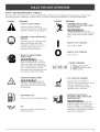
SAFETY
AND
_NTERNAT_ONAL
SYMBOLS
This operator's manual describes safety and international symbols and pictographs that may appear on this product.
Read the operator's manual for complete safety, assembly, operating and maintenance and repair information.
SYMBOL
MEANING
SYMBOL
Indicates danger, warning, or
_ SAFETY
ALERT
SYMBOL
caution. May
be used
in conjunction
with other symbols or pictographs.
,' WARNING
MANUAL
THROWN OBJECTS AND
ROTATING CUTTER CAN CAUSE
SEVERE iNJURY
•
WEAR EYE AND HEARING
PROTECTION
WARNmNG:
Donot
operate without the proper guards in
place. Keep away from the rotating
tines.
- READ OPERATOR'S
Read the Operator's Manual(s) and
follow all warnings and safety
instructions. Failure to do so can
result in serious injury to the
operator and/or bystanders.
MEANING
I
O
', ON/OFF STOP CONTROL
ON / START / RUN
ON/OFF STOP CONTROL
OFF or STOP
WARNmNG: Thrown
objects and loud noise can cause
severe eye injury and hearing loss.
Wear eye protection meeting ANSI
Z87.1-1989 standards and ear
protection when operating this unit.
Use a full face shield when needed.
', KEEP BYSTANDERS AWAY
WARNING:
Keepa,
bystanders,
especially
children
and
pets,atleast
50 feet(I5 m.)fromthe
operating
area.
UNLEADED
FUEL
Always use clean, fresh unleaded fuel.
', CHOKE
CONTROL
2 _ PARTIAL choke position.
3 _ RUN position.
HOT SURFACE WARNING
Do not touch a hot muffler or
cylinder. You may get burned. These
parts get extremely hot from
operation. When turned off they
remain hot for a short time.
GARDEN CULTIVATORS ROTATING TINES CAN CAUSE
SEVERE iNJURY
WARNING:
', OIL
Refer to operator's
proper type of oil.
manual for the
Stop the
engine and allow the tines to stop
before installing or removing tines,
or before cleaning or performing any
maintenance. Keep hands and feet
away from rotating tines.
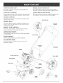
STARTER
ROPE
WHEEL
GRIP
ADJUST
BRACKET
The starter
rope gripisattachedtoan eyebo[tinthe
The wheel adjustbracketisattachedto thetailpiece
bracket,[tisused toadjustthewheels higheror tower.
THROTTLE
EDGER
CONTROL
Squeezing the throttle control speeds up the engine and
engages the tines. Release the handle to stop the tines.
CHOKE
WHEEL
CONTROL
STOP/OFF (0)
BULB
The primerbulbisused (inconjunctionwiththechoke
[ever)
to enrichthefuelmixtureinthecarburetor
when
starting
a coldengine,
ON/OFF
BLADE
The edger wheel and Made areshipped unnattachedto
thecultivator.
They areused forvertical
edging,
The choke [ever is used to enrich the fuel mixture when
starting
a coldengine.
PRIMER
AND
Throttle
Controm
STOP CONTROL
The switch must be in the On ([) position to start the
engine, and in the Off (O) position to stop it,
HANDLEBAR
KNOBS
The handlebarknobs areused to locktheupper handle
in a set position.
FRONT
//
START/ON
([}
HANDLE
Use the front handle to transport the cultivator.
The cultivator tines cultivate, furrow and prepare a
garden for seeding.
Handmebar
Knob
Handlebar
Muffler
\
Starter Rope Grip
Primer Bumb
Choke
Controm
Wheel Support
Bracket
Cultivator
Wheem
Edger
Blade
NOTE: This unit is shipped without gasoline or oil [n
order to avoid damage to the unit, refer to 0i/
and Fuel Information to put oH and gas in the
crankcase before attempting to start it.
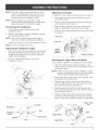
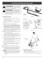
Adjusting
Tine
Depth
To adjust the wheel support bracket proceed as follows:
1. Stop engine and disconnect spark plug to avoid
accidental starting.
NOTE: Before setting up your cuHtivator / edger,
disconnect the spark pHugwire from the spark
pHugand ground to a stud on the engine.
2.
Positioning
3. Slide the wheel support bracket up or down in the
tailpiece, aligning the holes to the desire height.
the Handlebars
1. Loosen the two knobs on the inside of the
handHebars (Fig. 1).
2.
4.
With the unit upright, swing the handHebars up into
the operating position (Fig. 1).
Cotter Pin
i_
/.
_
/
Tighten the knobs to secure the handHebars in pHace.
NOTE: Do not over-tighten
Adjusting
the
the knobs.
Handmebar
Height
Wheel
1. Remove the knobs and mounting boHts and reinstall
them through either the top or bottom holes in the
handlebar assembly (Fig. 2) in order to adjust the
height of the handlebars.
2.
Place the clevis pin through the hole and secure with
a cotter pin.
Clevis Pin.
NOTE: Take care not to pinch the throttHe came or
switch wires when )ositioning the handHebar.
3.
Remove cotter pin from the clevis pin and slide pin
out of tailpiece bracket (Fig. 3).
Be sure to tighten the knobs to secure the
handlebars in place.
Support
Bracket
Tailpiece
Bracket
F_g.3
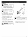
Attaching
the
Edger
Wheel
And
Blade
To convert the cultivator to an edger proceed as follows:
1.
Push the On/Off switch to Off (O) position to stop
engine and tines and disconnect spark plug to avoid
accidental starting.
NOTE: [t may be necessary to lay the cultivator / edger
back in a horizontal position on a flat level surface
with the upper handle touching the ground.
2.
Remove the click pin from each end of the tine shaft
and slide the tines off the shaft.
3. Slide the edger wheel, with the hub facing inward,
onto the right side of the tine shaft and secure with
the click pin in the inside hole (Fig. 4).
4.
Slide the edger blade with the hub facing out onto
the left side of tine shaft and secure with the click pin
in the inside hole (Fig. 4).
5. Guide the edger blade along a flowerbed, sidewalk,
or driveway with the edger wheel along the outside
edge. Use the edger guide line to line up edger blade.
F_g. 1
Edger Guide
Top HoJe
Line
Hand,ebars
Hand
ebar
-----_
Washer z
_/iC
(:_:
I::"
.,._t
Hub
f'_
/
Edger Wheel
Click Pin
Bottom HoJe
i
F_g.2
Edger Blade
F_g. 4
WARNING:
OVERFULUNG OUL
CRANKCASE MAY
CAUSE SERUOUS PERSONAL (NJURY.
Check and maintain the proper oU (eve( in
the crank case; it is important and cannot
be overemphasized. Check the oU before
each use and change it as needed. See
Changing the 0#.
4-Cyde
Recommeded
OiJ Type
the crankcase
Using
the proper
is extremeHy
type and weight
important.
of oU in
Check the oU before each use and change
the oU reguHaHy. Using incorrect or dirty oU can cause
premature engine wear and faUure.
Use a high-quality SAE 30 weight oU of APJ (American
PetroHeum Institute) service class SF, SG, SH.
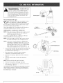
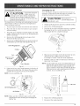
Adding
Mof.or Oil
OiJ to Crankcase:
F_g.5
OHFHI
_
_,\
JnitiaJ Use
NOTE: This unit is shipped without oil. In order to avoid
damage to the unit, put oil in the crankcase
before attempting to start unit.
Your unit is supplied with one 3.4 fluid oz. (100 ml.)
bottle of SAE 30 SF, SG, SH oil (Fig. 5).
NOTE: Save the bottle to measure the correct amount
for future oil changes. See Changing the Off.
F_g.6
NOTE: Your new 4-Cycle cultivator is shipped for
operation in conditions above 40°F (4°C). For
cold weather operation, where temperatures
plummet below 40°F (4°C), use a high-quality
SAE 10W30 weight oil of API (American
Petroleum Institute) service class SF, SG, SH.
F(()
Pmug/Dipstick
1. Unscrew the oil bottle top and remove the paper seal
covering the opening. Replace the top and cut the
tip off the funnel spout (Fig. 5).
2. Place the unit on a flat level surface with the
cultivator in a horizontal position (Fig. 6).
3. Remove the oil plug / dipstick from the crankcase
(Fig, 7).
4. Pour the entire bottle of oil into the oil fill hole
(Fig. 8).
Ho(e
F_g.7
NOTE: Never add oil to the fuel or fuel tank.
5. Remove the tag from oil fill plug / dipstick.
6.
Wipe up any oil that may have spilled and reinstall
the oil fill plug / dipstick.
The importance of checking and maintaining the proper
oil level in the crankcase cannot be overemphasized.
Check oil before each use and change as specified in
the Maintenance Schedule.
F_g.8
Recommended FuemType
OMfueHis the primaryreasonfor improper
unit performance.Besureto usefresh,
cHean,
unHeaded
gasoHine.
Fueling
NOTE:Thisisa fourcycleengine, In order
2.
to avoid
damage to the unit, do not mix oil with gasoline.
Definition
of Blended Fuels
Today's fueHsare often a Mend of gasoHine and
oxygenates such as ethanoH, methanoH or MTBE (ether).
AHcohoH-Mended fueHabsorbs water. As HittHeas 1%
water in the fueHcan make fueHform acids when stored.
When using aHcohoH-Mended fueH, use fresh fueHthat is
Hessthan 60 days oM.
Using Blended Fuels
Jfyou choose to use a Mended fueH,or if its use is
unavoidaMe, follow recommended precautions:
•
AHways use fresh unHeaded gasoHine
•
Use the fueHadditive STA-BIL ® or an equivalent
•
Drain tank and run the engine dry before storing unit
Using Fuel Additives
The use of fuel additives, such as STA-BJL <_Gas
Stabilizer or an equivalent, will inhibit corrosion and
minimize the formation of gum deposits. Using a fuel
additive can keep fuel from forming harmful deposits in
the carburetor for up to six (6) months. Add 0.8 oz.
(23 mH.)of fuel additive per gallon of fuel according to the
instructions on the container. NEVER add fuel additives
directly to the unit's gas tank.
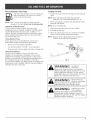
1.
the Unit
Remove fuel cap. Remove the tag from the fuel tank
neck.
NOTE: Fill or add fuel to the tank only when the
cultivator is in a horizontal position (Fig. 9).
Place spout of gas container into the fill hole on the
fuel tank and fill tank.
NOTE: Do not overfill tank.
3. Wipe up any gasoline that may have spilled.
4.
Reinstall the fuel cap.
5.
Move the unit at Heast 3O ft. (9.1 m) from the fueHing
source and site before starting the engine.
NOTE: Dispose of the old gasoline in accordance to
Federal, State and Local regulations.
FWg.9
WARNmNG: G
,so,ne
extremely,
flammable. Ignited Vapors may explode.
stop the engine and allow it to cool
g the fuel tank. Do not smoke
while filling the tank. Keep sparks and open
flames at a distance from the area.
WARNING:
Remove
fuen
cap
slowly to avoid injury
from fuel spray,. Never operate the unit
without the fuel cap securely' in place.
raNG:Awelldd ventilated
fuel in a clean,
outdoor area. Wipe up any spilled fuel
immediately. Avoid creating a source of
nition for spilt fuel. Do not start the engine
fuel vapors dissipate.
WARNING:
ON (J)\_
Operatethisunitonly
ina well-ventilated
outdoorarea,Carbon monoxide exhaustfumes
can be lethal
ina confinedarea.
WARNING:
\
OFF (0)
Avoid
acddental
starting. Make sure
you are in the starting position when pulling
the starter rope (Fig. 12). To avoid serious
injury, the operator and unit must be in a stable
gosition while starting.
Starting
instructions
1. Check the oil level in the crankcase.
Checking the Off Level
2.
Fig. 10
Refer to
Choke Lever
Fill the fuel tank with fresh, clean unleaded gasoline.
Refer to Fueling the Unit.
Position
3.
Put the On/Off Stop Control in the ON [1] position
(Fig. 10).
Position
4.
Place the choke lever in Position 1 (Fig. 11).
J
5.
Fully press and release the primer bulb 10 times,
slowly. Some amount of fuel should be visible in
the primer bulb and fuel lines (Fig. 11). If you can't
see fuel in the bulb, press and release the bulb as
many times as it takes before you can see fuel in it.
6.
Hold the throttle and handlebar with one hand and
grab the starter rope with your other hand. Use your
foot to hold down the cultivator (Fig. 12).
3
2
Position 1
Primer Bulb
Fig. 11
NOTE: Tilt the unit back slightly to bring the tines off the
ground when starting.
7. While squeezing the throttle control, pull the starter
rope out a short distance, until you feel some
resistance. This is usually around 2-4 inches. Then pull
the rope smoothly and briskly. Repeat this 5 times.
8.
Move the choke lever to Position 2.
9. While squeezing the throttle control, pull the starter
rope in the same manner as explained in Step 7. Pull
1 to 3 times to start the engine.
Starter Rope
\
10. Keep the throttle squeezed and allow the engine to
warm up for 15 to 30 seconds.
\
\
11. Place the choke lever in Position 3. Release the
throttle control to the idle position and begin
operation.
mr... The engine does not start, go back to step 3.
mr... The engine fails to start after a few attempts, place
the choke lever in Position 3 and squeeze the
throttle control. Pull the starter rope briskly 3 to 8
times. The engine should start. If not, repeat.
JF WARM°°°
If the engine is already warm, make sure
the On/Off Stop control is in the ON position and
start the unit with the choke lever in Position 2.
After the unit starts, move the choke lever to
Position 3.
10
Fig. 12
Stopping
Instructions
1.
Release your hand from the throttle control. Allow the
engine to cool down by idling.
2.
Put the On/Off Stop Control in the OFF (O) position.
Operating
Tips
WARNmNG:
Dress propedy to
reduce the riskof
unjury when operating this unit. Do not
wear loose clothing orjeweky. Wear eye
and ear/hearing protection. Wear heavy
long pants, boots and gloves. Do not wear
short pants, sandals or operate barefoot.
1.
Move the cultivator to the work area prior to starting
the engine. Transport the cultivator by pushing it on
wheels or carrying it by the handle center tube.
WARNmNG: To
prevent serious
personal injury,
never pick-up or carry the unit while the
engine is running,
2.
Start the unit by foiiowing the Starting instructions
3.
With the engine running and the tines off the ground,
depress the throttle control to increase the engine
speed.
4.
While holding the upper handle with both hands,
slowly lower the cultivator until the tines make
contact with the ground (Fig. 13).
5.
Fig. 13
Transporting
As cultivating action begins, tilt the cultivator up
slightly using the handle so that the tines can
penetrate the ground.
6.
Once the ground has been broken, continue at a
moderate pace until you are familiar with the controls
and the handling of the cultivator.
7.
[f the tines are digging too deep or not deep enough,
adjust the wheel bracket as described in Adjusting
Tine Depth.
WARNmNG: To
prevent serious
personal injury, use
the Unit
[ N G:
To prevent serious
personal injury,
always stop the engine when operation is
delayed or when transporting the unit from
one location to another
1. Stop the engine.
2. Tilt the unit back until the tines clear the ground.
3.
Push or pull the unit to the next location to be
cultivated.
extreme caution when reversing
or pulling the unit towards you.
11
MAINTENANCE
SCHEDULE
Perform these required maintenance procedures at the
frequency stated in the tame. These procedures shouid
aBo be a part of any seasonai tune-up.
NOTE: Maintenance, repiacemenb or repair of the
emission controi devices and system may be
performed by any non-road engine repair
estaMishment, individuai or authorized service
deabr.
NOTE: Some maintenance procedures may require
speciai toois or skills. If you are unsure about
these procedures take your unit to any non-road
engine repair estaMishment, individual or
authorized service deabr.
MAINTENANCE
JN G: To
prevent serious
injury, never perform
maintenance or repairs with unit running.
AJways service and repair a cool unit.
Disconnect the spark plug wire to ensure that
the unit cannot start.
REQUIRED
REFER TO
Before starting engine
Fill fuel tank with fresh fuel
Check oil
Page 9
Page 13
Every 10 hours
Clean and re-oil air filter
Page 14
First change at 10 hours
Every 25 hours thereafter
Every 25 hours
Change oil
Change oil
Clean spark arrestor
Page 13
Page 13
Page 17
10 hours on new engine
Every 25 hours
Every 25 hours
Check rocker arm to valve clearance and adjust
Check rocker arm to valve clearance and adjust
Check spark plug condition and gap
Page 15
Page 15
Page 17
Tine
Removam
and
Mace one "A" tine and one "B" tine onto the shaft,
Repmacement
All 4 tines should be replaced at the same time because
they will wear evenly through normal use. Work on one
side at a time.
WARNING:
6.
Secure the new tines to the shaft with click pins. It
may be necessary to wash the dirt off the tines and
shaft for ease of removal.
To
prevent serious
personal injury,
always wear heavy gloves when handling
the tines.
1. Put the On/Off Stop Control in the STOP (O) position
and disconnect the spark plug wire.
NOTE: It may be necessary to lay the cultivator back in a
horizontal position on a flat level surface with the
upper handle touching the ground.
2.
3.
4.
12
Remove the click pin from each end of the tine shaft.
Slide the tines off of the shaft (Fig. 14).
Clean and oil the shaft.
Slide on the new tines with the hubs facing out. The
four tines are market with the letters "A" and "B."
Click Pin
Fig. 14
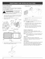
Checking
the OimLevem
Changing
, To prevent extensive
• engine wear and
damage to the unit, always maintain the
proper oil level in the crankcase. Never
operate the unit with the oil level below the
bottom of the dipstick.
The importance of checking and maintaining the proper
oil level in the crankcase cannot be overemphasized.
Check oil before each use:
1. Stop the engine and ailow oil to drain into the crankcase.
2.
Place the unit on a fiat, level surface to get a proper
oil level reading.
3.
Keep dirt, grass clippings and other debris out of the
engine. Clean the area around the oil fill plug/dipstick
before removing it.
4.
Remove the oil fill plug/dipstick
Reinsert it all the way back in.
the
Oim
For a new engine, change the oil after the first 10 hours of
operation. Change the oil while the engine is still warm. The
oil wiI! flow freely and carry away more impurities.
1
|
• Wear gHoves to
" prevent injury when
handling the unit.
1.
UnpHug spark pHugboot to prevent acddentaH starting.
2.
3.
Remove the oiHfirthpHugidipstick.
Pour the oiHout of the oiHfirthhoHeand into a container
by tipping the unit to a verticaH position (Fig. 17).
AHHowampHe time for compHete drainage.
and wipe off oil.
5. Remove the oil fill plug/dipstick and check the oil level.
Oil should be up to the top of the dipstick (Fig. 15).
Fig. 17
4. Wipe up any oil residue on the unit and dean up any
oiHthat may have spiHHed.Dispose of the oiH
according to Federal State and HocaHreguHations.
Add 1.4_1.5 Oz.
(41_44 ram)
5.
Top of Dipstick
6.
Fig. 15
If the level is low, add a small amount of oil to the oil
firthhoHeand recheck (Fig. 16). Repeat this procedure
untiHthe oiHHeveH
reaches the top of the dipstick.
RefiHH
the crankcase with 3.4 fluid ounce (100 mH)of
SAE 30 SF, SG, SH oil
NOTE: Use the bottle and spout saved from initial use to
measure the correct amount of oil The top of the
HabeHon the bottHemeasures approximateHy 3.4
ounces (100 ml). Check the level with the dipstick.
If the HeveH
is How,add a smaHHamount of oiHand
recheck. Do not overfiHH(Fig. 18).
NOTE: Do not overfiHHthe unit.
-_
Fig.
16
NOTE: Make sure the O-ring is in pHace on the oiHfirth
pHug/dipstick when checking and changing the
oiH(Fig. 16).
Fill Level
Fig. 18
6_
RepHacethe oiHfirthpHugidipstick.
7.
Reconnect the spark pHugboot.
13
Air Filter Maintenance
4, Apply enough clean SAE 30 motor oil to lightly coat
the filter (Fig. 21).
Clean and re-oil the air filter every 10 hours of operation.
it is an important item to maintain. Faiiure to maintain the
air fiiter will[ VOmD the warranty.
WARNING:
To
serious
personal injury,
always turn the unit off and allow it to cool
before you clean or service it.
/
1. Open the air filter cover. Push the tab on the left side
of the cover in, swing the air filter cover out and off
the air filter housing (Fig. 19).
2.
Remove the air filter and the screen that sits
behind it (Fig. 19).
Screen
Air Filter
/
Fig. 21
5.
Squeeze the filter to spread and remove excess oil
(Fig. 21).
6.
Replace the filter and screen (Fig. 19).
NOTE: If the unit is operated without the air filter, you
will VOID the warranty.
7.
Reinstall the air filter cover. Position the hooks on
the right side of the air filter cover into the slots at
the right side of the air filter housing.
8.
Swing the cover to the left until the tab on the air
filter cover snaps into place in the slot on the left
side of the air filter housing (Fig. 18).
Carburetor
Choke Lever
b_
Adjustment
The idle speed of the engine is adjustable. An idle
adjustment screw is reached though a hob in the top of
the engine cover (Fig. 22).
1
NOTE: Careless adjustments can seriously damage your
unit. An authorized service dealer should make
carburetor adjustments.
Check Fuel
Slot
\\
Air Filter
Tab
Fig. 19
3.
Wash the filter in detergent and water (Fig. 20). Rinse
the filter thoroughly and allow it to dry.
Fig. 20
14
Old fuel is usually the reason for improper unit
performance. Drain and refill the tank with fresh fuel prior
to making any adjustments, Refer to Oil and Fuel
Information.
Clean Air Filter
The condition of the air filter is important to the operation
of the unit. A dirty air filter wiii restrict air flow. This is
often mistaken for an out of adjustment carburetor.
Check the condition of the air filter before adjusting the
idle speed screw, Refer to Air Filter Maintenance,
Adjustldme
SpeedScrew
Rocker
WARNmNG:
Thisunitneeds to
run duringidHe
speed adjustment, Wear protective cHotMng
and observe aHH
safety instructions to
prevent serious personaH injury,
Arm
Cmearance
This requires disassembly of the engine. If you feel
unsure or unquaHified to perform this, take the unit to an
authorized service center.
NOTE: Inspect the valve to rocker arm clearance with a
feeler gauge after the first 10 hours of operation
and then every 25 hours of operation thereafter.
If, after checking the fueHand cHeaning the air fiHter, the
engine stiHH
wiHHnot idHe,adjust the idHespeed screw as
follows:
• The engine must be coHd when checking or adjusting
the vaHvecHearance.
1.
, This task shouHd be performed inside, in a dean,
dust free area.
Start the engine and Jetit run at a high idle for a minute
to warm up. Refer to Starting/Stopping Instructions.
NOTE: Ensure the tines are not in contact with the
ground when adjusting the idHe.
2.
To adjust the rocker arm cHearance:
1.
Release the throttle trigger and let the engine idle. If the
engine stops, insert a small phillips or fiat blade
screwdriver into the hole in the air filter/muffler cover
(Fig. 22), Turn the idle speed screw in, clockwise, 1/8
of a turn at a time (as needed} until the engine idles
smoothly.
Remove the two (2) screws on top of the engine cover
with a Hat-head or T-25 Torx screwdriver (Fig. 23),
Top View Of The Engine
Remove
Screws
Eng
NOTE: The tines shouHdnot rotate when the engine idHes.
3.
If the tines rotate when the engine idles, turn the idle
speed screw counterclockwise
1/8 of a turn at a time
(as needed}, to reduce idle speed.
/lJ
J
Checking the fuel cHeaning the air fiHter, and adjusting
the idHespeed shouHd soHvemost engine probHems. If not
and aHH
of the following are true:
%
• the engine wiHHnot idHe
• the engine hesitates or staHHs
on acceHeration
Muffler
• there is a Hossof engine power
Have the carburetor adjusted by an authorized service dealer.
/
Fig. 23
Idle Adjustment Screw
2.
Remove the screw behind the engine cover (Fig. 24),
Screw
Fig. 22
Fig. 24
15
3. Disconnect the spark pHugwire.
4.
Adjusting
Rocker Arms
CHean dirt from around the spark pHug. Remove the
spark pHugfrom the cyHinder head by turning a 5/8 in.
socket counterclockwise.
Nuts
iNTAKE
5. Remove the engine cover.
NOTE: To ease engine cover removal pull the starter
rope out a [ittHeto give some shack.
6.
EXHAUST
CHean dirt from around the rocker arm cover.
Remove the screw hoHding the rocker arm cover with
a [arge flat Made screwdriver or Torx T-25 bit
(Fig. 25). Remove the rocker arm cover and gasket.
Feeler Gauge
f
Rocker Arm Cover
Fig. 26
Adjusting
Rocker Arm
Fig. 25
7.
.003-.006
(.076=.152
in.
Pull the starter rope showilyto bring the piston to the top
of its travel, (known as top dead center). Check that:
Sauge
• The piston is at the top of its trave[ whiHe Hooking in
the spark pHughole (Fig. 25)
•
Both rocker arms move freely, and both valves are
closed
Valve Stem
If these statements are not true, repeat this step.
8_
Slide the
the valve
between
Measure
feeler gauge between the rocker arm and
return spring. Measure the clearance
the valve stem and rocker arm (Fig. 27).
both the intake and exhaust valves.
The recommended clearance for both intake and
exhaust is .003 - .006 in. (.076 - 0.152 mm). Use a
standard automotive .005 in. (0.127 mm) feeler gauge.
The feeler gauge should slide between the rocker arm
and valve stem with a slight amount of resistance,
without binding. See Figure 26 and 27.
Fig. 27
9.
If the clearance is not within specification:
a. Turn the adjusting nut using a 5/16 inch (8 mm)
wrench or nut driver (Fig. 27).
• To increase clearance, turn the adjusting nut
counterclockwise.
• To decrease clearance, turn the adjusting nut
clockwise.
b. Recheck both clearances, and adjust as necessary.
10. Reinstall the rocker arm cover using a new gasket.
Torque the screw to 20-30 indb (2.2-3.4 Nom).
11. Reinstall the engine cover. Check alignment of the
cover before tightening the screws. Tighten screws.
12. Check the spark plug and reinstall. See Replacing
the Spark Plug.
13. Replace the spark plug wire.
16
Repmacing the Spark
Plug
Use a replacement part number 180852 spark plug. The
correct air gap is 0.025 in. (0.655 mm.). Remove the plug
after every 25 hours of operation and check its
condition.
Spark Arrestor
Maintenance
1. Remove the muffler cover. See Rocker Arm Clearance.
2. With a flat blade screwdriver or Torx T-20 bit,
remove the screw attaching the spark arrestor cover
to the muffler (Fig. 29).
1. Stop the engine and allow it to cool. Grasp the plug
wire firmly and pull the cap from the spark plug.
2.
3.
Clean dirt from around the spark plug. Remove the
spark plug from the cylinder head by turning a 5/8 in.
socket counterclockwise.
Muffler
Screen
Replace cracked, fouled or dirty spark plug. Set the air
gap at 0.025 in. (0.655 mm.) using a feeler gauge (Fig. 28).
0.025 in.
{0.655 ram.)
Fig. 28
the cylinder.
4.
Spark Arrestor
Fig. 29
3.
Pull the tab on the spark arrestor cover out of the
muffler. Remove the spark arrestor cover.
4.
Remove the spark arrestor screen from the spark
arrestor cover.
5.
Clean the spark arrestor screen with a wire brush or
replace it.
6.
Reinstall the spark arrestor screen, spark arrestor
cover and screw.
Install a correctly-gapped
spark plug in the cylinder
head. Turn the 5/8 in. socket clockwise until snug.
If using a torque wrench torque to:
110-120 in.qb. (12.3-13.5 N,m)
Do not over tighten.
17
Cleaning
the Unit
WARNmNG: To
avoid
eriou
personal injury,
always turn the unit off and allow it to cool
before you clean or perform any
maintenance on it.
Use a small brush to clean off the outside of the unit
and to keep the air vents free of obstructions.
Do not use strong detergents or petroleum based
cleaners, such as kerosene. Some household
cleaners contain aromatic oils such as pine and
lemon that can damage the plastic housings or
handles. Wipe off any moisture with a soft cloth.
Storage
• Never store the unit with fuel in the tank where
fumes may reach an open flame or spark.
•
Allow the engine to cool before storing.
Store the unit in a locked up area to prevent
unauthorized use or damage.
Store the unit in a dry, well-ventilated area. Do not
store next to corrosive material like fertilizer.
Store the unit out of the reach of children.
Long Term Storage
If the unit will be stored for an extended time:
Drain all gasoline from the gas tank into a container.
Do not use gas that has been stored for more than
60 days. Dispose of the old gasoline in accordance
with Federal, State and Local regulations.
18
2. Start the engine and allow it to run until it stalls. This
ensures that all gasoline has been drained from the
carburetor.
3. Allow the engine to cool. Remove the spark plug and
put 1 oz. (30 mi) of high quality motor oil into the
cylinder. Puii the starter rope slowly to distribute the
oii. Reinstaii the spark plug.
NOTE:: Remove the spark plug and drain aii of the oil
from the cylinder before attempting to start the
unit after storage.
4. Change the oil, referring to the Changing the 0//
section. Dispose of the old oil in accordance with
Federal, State and Local regulations.
5. Thoroughly clean the unit and inspect for any loose
or damaged parts. Repair or replace damaged parts
and tighten loose screws, nuts or bolts.
6. To take up less storage area, loosen the handlebar
knobs and fold the handlebar down. The unit is
ready for storage.
Allow the engine to cool before transporting.
•
Secure the unit while transporting.
•
Drain the fuel tank before transporting.
Tighten fuel cap before transporting.
CAUSE
ACTION
Empty fueHtank
Fill fueHtank with new fueH
Primer buHbwasn't pressed enough
Press primer buHbfully and sHowly 10 times
is flooded
Use starting position with the starting lever in Position 3
OHdfueH
Drain gas tank and add fresh fuel
FouHed spark pHug
Replace or clean the spark plug
Mugged spark arrestor
Clean or replace spark arrestor
CAUSE
ACTION
Air fiHteris pHugged
Replace or cleantheairfilter
OHdfueH
Drain gas tank and add fresh fuel
Improper carburetor adjustment
Adjust according to the Carburetor Adjustments
CAUSE
section
ACTION
OM fueH
Drain gas tank and add fresh fuel
Improper carburetor adjustment
Take to an authorized service dealer for an adjustment
Dirty air fiHter
Clean or replace the air filter
Mugged spark arrestor
Clean or replace spark arrestor
CAUSE
ACTION
OHdfueH
Drain gas tank and add fresh fuel
Improper carburetor adjustment
Take to an authorized service dealer for an adjustment
FouHed spark pHug
Replace or clean the spark plug
Mugged spark arrestor
Clean or replace spark arrestor
CuHtivator tines bound with dirt or grass
Stop the unit, switch the On/Off Stop Control to
STOP, clean and remove any debris binding the tines
CAUSE
OiHfiH pHugidipstick Hooseor missing o-ring
CAUSE
Spark plug gap is too small/close
ACTION
Tighten oil fill plug/dipstick,
replace o-ring
ACTION
Adjust gap to 0.025"
NOTE:For
repairs beyond the minor sdjustments
listed above, contact
your
center or other qualified
service center, or call 1 800 4 MY HOME
nearest
Sears
service
19
Engine Type .................................................................
Displacement
.................................................................
Idle Speed RPM .................................................................
Operating RPM .................................................................
Clutch Type .........................................................................
ignition Type .........................................................................
On/Off Stop Control ................................................................
VaUve cUearance (intake and exhaust)
......................................
Spark Plug Gap ............................................................
Lubrication
..........................................................................
Crankcase Oil Capacity
............................................................
Fuel ................................................................................
Carburetor ................................................................
Starter ............................................................................
Muffler .......................................................................
ThrottUe ..........................................................................
FueUTank Capacity .................................................................
CuNvating Path Width (Maximum) ................................................
CuUtivating Depth (Maximum)
....................................................
Approximate Weight (no fuel) ........................................................
Air-Cooled, 4°Cycle
1.6 cu. in. (262 cc)
3,000-3,600 rpm
7,200-8,800 rpm
Centrifugal
Electronic
Rocker Switch
003-.006 in. (.076-.0152 mm)
0.025 inch (0.655 mm)
SAE 30 Oil
3.4 oz (100 ml)
Unleaded
Diaphragm,
All-Position
Auto Rewind
Baffled with Guard
Spring Return
15 oz (444 mU)
9 inches (22.86 cm)
6 inches (1524 cm)
25 Ib. (11.5 kg)
*All specifications are based on the latest product information available at the time of printing. We reserve the right to
make changes at any time without notice.
2O
21
ENGmNE PARTS
- MODEL
4-CYCLE
SEARS
CULTIVATOR
GAS CULTIVATOR
Part Numbers On FollowingPage
@
@
®
E23
ENGINE
PARTS
4-CYCLE
- MODEL
PaR No.
753-04028
7!)1-182339
7!)1-182651
7!)1-182652
791-181025
791-182098
791-182099
791-182340
791-182101
791-182100
791-182341
791-182103
791-181038
791-182102
791-181033
791-182745
Description
Engine Cover
Engine Cover Screws
Starter Rope Eyelet
Eyelet Nut
Valve Cover Screw
Valve Cover
Valve Cover Gasket
17
18
19
20
21
22
23
24A
791-182344
753-1226
791-182749
791-181034
753-04029
791-182348
791-182732
791-182654
Cylinder Screw
Intake Baffle
Carburetor Mount Gasket
Nut
24B
753-1225
753-04030
791-182655
27
28
2!)
30
31
32
33
34
35
36
37
38
39
40
41
42
43
44
45
46
47
791-182097
791-181000
791-182409
753-04031
791-182657
791-182658
791-18265!)
753-04033
791-182352
791-182353
791-181080
753-04035
753-04034
791-182356
753-1232
791-181048
791-181047
791-180890
791-181045
791-181046
791-182361
E24
CULTIVATOR
GAS CULTIVATOR
item
1
2
3
4
5
6
7
8
9
10
11
12
13
14
15
16
25
26
SEARS
Rocker
Rocker
Rocker
Rocker
Valve
Valve
Push
Push
Adjustment
Arm Pivot
Arm
Arm Stud
Nut
Spring Retainer
Spring
Rod Guide
Rod
Cylinder Assembl
(includes 11-14)
Carburetor
Carburetor
Carburetor
Mount (includes 20)
Mount Screw
Gasket
Carburetor w/Primer (See Lower Cultivator
Page For Carburetor Identification)
Carburetor w/Primer (See Lower Cultivator
Page For Carburetor Identification)
Air Filter Gasket
Air Filter
(includes
Breather
Grommet
Washer
Air
Air
Air
Air
Cover Assembly
27, 28, 31-33)
Tube Assembly
Washer
Filter Mounting
Filter Plate
Filter
Filter Cover
Screw
Fuel Cap
Fuel Return Line
Fuel Pick-Up Line with Filter
Screw
Washer
Fuel Tank Assembly (includes 34-36)
Fuel Tank Shield
Muffler Baffle
Muffler Gasket
Muffler (includes 42, 44-46)
Spark Arrestor Screen
Screen Cover
Screw
Muffler Mounting
Screw
Parts
Parts
item
48
49
50
51
52
Part No.
753-04288
791-182748
753-04286
7!)1-182366
791-181079
Description
Pulley Retainer Assembly
Recoil Pulley
Recoil Spring Canister
Nut Clip
Pull Handle
53
54
55
56
57
58
59
60
61
62
63
791-611061
791-182661
791-181020
753-04038
7!)1-182537
791-182368
753-1238
791-153592
753-1239
791-181345
753-04039
Rope Guide
Rope
Starter Housing Screw
Starter Housing Assembly
Wire Grommet
Clutch Washer
Clutch with Washer
Clutch Drum
Clutch Cover
Clutch Cover Screw
Lead Wire
64
65
66
67
753-04040
7!)1-181065
7!)1-182736
7!)1-181861
Ignition Module with Screws
Spacer
Flywheel
Screw
68
89
70
71
72
73
74
75
791-182743
791-182376
7!)1-182375
7!)1-182379
7!)1-181015
753-1242
791-181013
791-181012
Shroud Assembly with Screws (includes 67)
Crankcase Assembly (includes 70 & 71)
90 ° Elbow
Breather Hose
Cam Gear
Cam Follower
Cam Bracket
Cam Bracket Screw
76
77
78
791-181040
7!)1-182374
7!)1-181018
Valves, Intake and Exhaust
Cylinder Gasket
Oil Pan Gasket
7!)
80
7!)1-182377
791-181020
Oil Pan (includes 78 & 80)
Oil Pan Screw
81
82
83
84
85
86
753-04041
791-182290
791-181009
791-181008
753-1243
7!)1-181006
Dipstick Assembly (includes 82)
O-Ring
Connecting Rod
Wrist Pin Button
Piston
Wrist Pin
87
88
89
90
7!)1-181005
7!)1-145569
753-1240
753-1241
Piston Ring Set
Anit-Rotation Screw
Screw
Nut
791-180852
753-04087
791-180142
753-04014
753-1248
Spark Plug
Short Block Assembly (includes 5-17, 69-87)
Starter Pawl Repair Kit
Carburetor Repair Kit
Gasket/Diaphragm
Repair Kit
Parts riot shown
(includes 48-55)
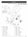
LOWER
CULTIVATOR
PARTS
- MODEL SEARS CULTIVATOR
4-CYCLE
GAS CULTIVATOR
If you have 24A Carburetor from
the Engine Parts pages, of this
parts list, then your replacement
Throttle Cable will be 5A. If you
have 24B Carburetor from the
Engine Parts pages then your
replacement Throttle Cable will
be 5B,
Item
1
2
3
4
5A
5B
6
7
8
9
10
11
12
13
14
15
16
17
18
Part
No.
753-04042
753-04043
791-182673
753-04044
753-04045
753-04147
753-04498
791-182899
753-04049
753-04499
791-182677
753-04052
753-04053
753-04054
753-04055
753-04056
753-04057
753-04058
753-04059
Description
Trotde Control
Torsion Spring
On/Off Switch
Foam Grip
Throttle Cable
Throttle Cable
Upper Handle
Bolt
Cable Tie
Flex Shaft
Knob
Shoulder Washer
Lower Handle
Screw
Front Handle
Lock Nut
Cotter Pin
Tailpiece Bracket Assembl
Clevis Pin
/
Item
19
20
21
22
23
24
25
26
27
28
29
30
31
32
33
34
35
36
Part No.
753-04060
753-04061
753-04062
753-04063
753-04064
753-04065
791-182678
753-04067
753-04075
753-04074
753-04073
753-04072
753-04071
753-04070
753-04069
753-04068
753-04500
753-04077
Description
Cap Screw
Lock Nut
Cap Push
Wheel Support Bracket Assembly
Wheel
Cap Screw
Washer
Tine Shield
Gear
Inner
Outer
Inner
Outer
Click
Box Assembly
Tine (right side)
Tine (right side)
Tine (left side)
Tine (leR side)
Pin
Edger Tine
Edger Wheel
Drive Shaft Housing
Anti Rotation Screw
E25
California
/ EPA Emission
Control
Warranty
Your Warranty Rights and Obligations
Statement
The California Ak Resources Board, EPA (Envkonmentd
Protection Agency), and Sears are pleased to explain the
emission Control System Warranty on your 2000 and later small off-road engine. In California and the 49 states, new
small off-road engines must be designed, built and equipped to meet the state's stringent anti-smog standards. Sears
must warrant the emission control system on your small off-road engine for the periods of time listed below provided
there has been no abuse, neglect or improper maintenance of your small off-road engine.
Your Emission control system may include parts such as the carburetor or fueNnjection system, the ignition system, and
catalytic converter. Also included may be hoses, belts, connectors and other emission-related assemblies.
Where a warrantable condition exists, Sears will repair your small off-road engine at no cost to you including diagnosis,
parts and labor.
The 2000 and later small off-road engines are warranted for two years. If any emission-related
defective, the part will be repaired or replaced by Sears.
part on your engine is
Owner's Warranty
Responsibilities
° As the small off-road engine owner, you are responsible for the performance of the required maintenance listed in your
operator's manual. Sears recommends that you retain all receipts covering maintenance on your small off-road engine,
but Sears cannot deny warranty solely for the lack of receipts or for your failure to ensure the performance of all
scheduled maintenance.
, As the small off-road engine owner, you should however be aware that Sears may deny you warranty coverage if your
small off-road engine or a part has failed due to abuse, neglect, improper maintenance or unapproved modifications.
You are responsible for presenting your small off-road engine to a Sears authorized service center as soon as problem
exists. The warranty repairs should be completed in a reasonable amount of time, not to exceed 30 days.
If you have any questions regarding your warranty rights and responsibilities,
you should call 1-800-4-MY-HOME.
Manufacturer's
Warranty
Coverage
, The warranty period begins on the date the engine or equipment is delivered to the retail purchaser.
• The manufacturer warrants to the initial owner and each subsequent purchaser, that the engine is free from defects in
material and workmanship which cause the failure of a warranted part for a period of two years.
Repair and replacement of warranted part will be performed at no charge to the owner at an authorized Sears service
center. For the nearest location please contact Sears at: 1-800-4-MY-HOME.
, Any warranted part which is not scheduled for replacement, as required maintenance or which is scheduled only for
regular inspection to the effect of "Repair or Replace as Necessary" is warranted for the period. Any warranted part
which is scheduled for replacement as required maintenance will be warranted for the period of time up to the first
scheduled replacement point for that part.
, The owner will not be charged for diagnostic labor which leads to the determination
If the diagnostic work is performed at an authorized Sears Service Center.
• The manufacturer
under warranty.
is liable for damages to other engine components
that a warranted part is defective.
caused by the failure of a warranted part still
° Failures caused by abuse, neglect or improper maintenance are not covered under warranty.
• The use of add-on or modified parts can be grounds for disallowing a warranty claim. The manufacturer
cover failures of warranted parts caused by the use of add-on or modified parts.
is not liable to
, In order to file a claim, go to your nearest authorized Sears Service Center. Warranty service or repairs will be provided
at all authorized Sears Service Centers.
• Any manufacturer approved replacement p[art may be used in the performance of any warranty maintenance or repair
of emission related parts and will be provided without charge to the owner. Any replacement part that is equivalent in
performance or durability may be used in non-warranty
maintenance or repair and will not reduce the warranty
obligations of the manufacturer.
• The following components are included in the emission related warranty of the engine, air filter, carburetor,
lines, fuel pick up/fuel filter, ignition module, spark plug and muffler.
primer, fuel