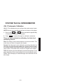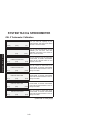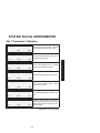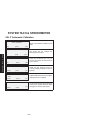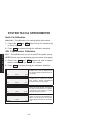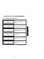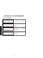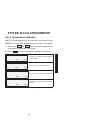
1
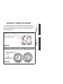
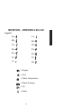
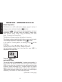
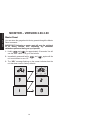
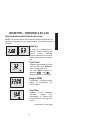
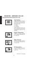
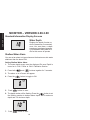
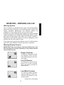
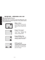
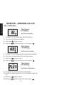
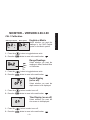
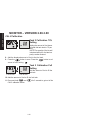
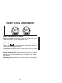
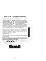
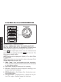
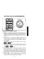
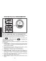
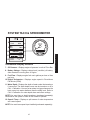
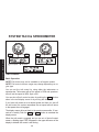
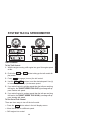
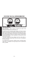
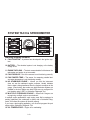
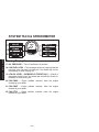
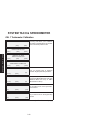
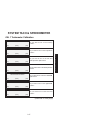
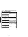
Operation Manual THIS MANUAL DESCRIBES THE SMARTCRAFT GAUGE SYSTEMS AVAILABLE FOR YOUR BOAT 2003, Mercury Marine 90-10229023 203 0 Part 2 NOTE: Software version will flash on screen at start up Part 1 System Tachometer and Speedometer Note: Look for RESET and Brightness arrows Part 2 1 MONITOR 2.00-3.00 Monitor Software Versions 2.00 & 3.00 SYSTEM TACH & SPEED For boats equipped with SmartCraft gauge systems, look to the descriptions below to identify the system in the boat. Please read about the SmartCraft system to get the best performance from them. Part 1 PRODUCT IDENTIFICATION 2 MONITOR 2.00-3.00 Part1 Monitor with Software Version 2.00 and 3.00 Legend . . . . . . . . . . . . . . . . . . . . . . . . . . . . . . . . . . . . 1-1 Basic Operation . . . . . . . . . . . . . . . . . . . . . . . . . . . . 1-2 Initial Power Up . . . . . . . . . . . . . . . . . . . . . . . . . . . . 1-2 Master Reset . . . . . . . . . . . . . . . . . . . . . . . . . . . . . . 1-4 Standard Information Display Screens . . . . . . . . . 1-5 Shallow Water Alarm . . . . . . . . . . . . . . . . . . . . . . . . 1-8 Warning System . . . . . . . . . . . . . . . . . . . . . . . . . . . . 1-9 Warning Display Screens . . . . . . . . . . . . . . . . . . . . 1-9 CAL 1 Calibration . . . . . . . . . . . . . . . . . . . . . . . . . . 1-11 CAL 2 Calibration . . . . . . . . . . . . . . . . . . . . . . . . . . 1-18 NOTE:This manual shows all the Monitor display screens that are available. Depending on your type of engine, not all these screens will apply. Monitor with Software Version 2.00 and 3.00 is compatible with: 2002 model year and newer Mercury Outboard Models that are designed for use with SmartCraft. All Mercury MerCruiser models designed for use with Smartcraft. MONITOR 2.00-3.00 1-0 Legend A= L= B= N= C= O= D= P= E= S= F= T= I= U= = Engine = Fuel = Water Temperature = Water Pressure = Oil = Alarm 1-1 MONITOR 2.00-3.00 MONITOR – VERSION 2.00-3.00 MONITOR 2.00-3.00 MONITOR – VERSION 2.00-3.00 Basic Operation The Monitor is an LCD multi-function display gauge. A variety of displays can be activated using the button. button scrolls the following displays: fuel used, Pressing the tachometer (RPM), fuel flow, power trim position, engine temp, water pressure, battery voltage, range (if calibrated), and water depth (if equipped with transducer). The Monitor will power up when the ignition is turned on. The display includes a backlight which allows you to read it at night. button. The backlight brightness is adjustable using In the event of a warning alarm, the warning icon(s) displayed. will be Initial Power Up (Or After Master Reset) Unit will display software level then flash the word “SEt” in conjunction with engine icon. Press the button. AUTO-DETECTION The unit will begin it’s “Auto-detection” of engine type procedure. In this procedure the Monitor checks with the engine control module (ECM) to see what type of engine you have and presets the data monitoring screens accordingly, (e.g., If Monitor detects an inboard engine connected to the data network it will turn off all engine/drive TRIM functions as these functions are not used in an inboard engine installation). The intention is to make initial setup easier. (continued on next page) 1-2 Initial Power Up (Or After Master Reset) Initial Auto-Detection Error Messages: Flashing “Stbd” – More than one of the engine computers (ECMs) are configured as a starboard engine. The engines must be programmed for proper engine location using a DDT or Quicksilver Diagnostic Tool. Flashing “nonE” – The gauge does not see any engine computers (ECMs). Please check wiring for bad connections and for proper amount of terminator resistors. Flashing “noSt” – None of the engine computers (ECMs) are configured as a starboard engine. Engines may not be compatible or must be programmed for proper engine location by using a DDT or Quicksilver Diagnostic Tool. Flashing “2001” – You will need to manually select your engine type. Use the button to scroll through the choices. Stnd = Stern Drive, Inbd = Inboard, JEtd = Jet Drive, Out2 = Outboard 2 Stroke, Out4 = Outboard 4 Stroke. Press to continue. 1-3 MONITOR 2.00-3.00 MONITOR – VERSION 2.00-3.00 MONITOR 2.00-3.00 MONITOR – VERSION 2.00-3.00 Master Reset You can return the gauge back to factory presets through the Master Reset command. IMPORTANT: Performing a master reset will reset the unit back to all factory defaults, thus eliminating any installation calibrations performed during set up of product. and for approximately 12 seconds. You will 1. Hold in see the word “dFLt”. Let go of the buttons. 2. Immediately press and hold in unit counts down to zero “0”. and again until the 3. The “SEt” message flashing on the screen indicates that the unit has been reset to factory defaults. 1-4 Standard Information Display Screens NOTE:This manual shows all the Monitor display screens that are available. Depending on your type of engine, not all these screens will apply. Start Up At start up, a momentary (1 second) screen displays the current monitor software version, followed by a 4 second display showing hours of engine use. Fuel Used Displays approximate fuel used since the last reset. Reset will return display back to 0. You can Reset anytime by pressing and buttons together momentarily. Engine RPM Tachometer – Displays engine speed in Revolutions Per Minute (RPM). Fuel Flow Displays current estimated individual engine fuel consumption in Gallons per hour (Gal/hr) or Liters per hour (Ltr/hr). (continued on next page) 1-5 MONITOR 2.00-3.00 MONITOR – VERSION 2.00-3.00 MONITOR 2.00-3.00 MONITOR – VERSION 2.00-3.00 Standard Information Display Screens Trim Position Displays trim position of the propulsion unit up to the maximum trim position, and then displays the trailer position. 0 = down, 10 = full trim 25 = full trailer. NOTE: This screen can be set to pop up whenever the trim switch is used. Refer to the CAL 1 Calibrations. Engine Temperature Displays the engine temperature in degrees Fahrenheit (°F) or Celsius (°C). Water Pressure Displays the engine temperature in degrees Fahrenheit (°F) or Celsius (°C). Oil Temperature Displays the engine oil temperature in degrees Fahrenheit (°F) or Celsius (°C). (continued on next page) 1-6 Standard Information Display Screens Oil Pressure Displays engine oil pressure in Psi or Bar. Battery Voltage Displays voltage level (condition) of battery. Range Displays estimated range based on current fuel consumption and fuel remaining in the tank that is connected to the system. The number displayed is an estimate of the distance you can travel on the remaining fuel at current boat speed. NOTE: Two requirements to activate this screen, 1.You must perform the fuel tank calibration in CAL 2. Refer to the CAL 2 Calibrations Section. 2.You must have a speed input device connected to the system (paddle wheel or pitot pressure transducer). (continued on next page) 1-7 MONITOR 2.00-3.00 MONITOR – VERSION 2.00-3.00 MONITOR 2.00-3.00 MONITOR – VERSION 2.00-3.00 Standard Information Display Screens Water Depth Displays the depth of water under the transducer if connected. NOTE: You must have a depth transducer (purchased separately) connected to the system in order for this screen to operate. Shallow Water Alarm You can set an alarm to trigger whenever the boat moves into water shallower than the alarm level. Setting Shallow Water Alarm. 1. The water depth screen must be displayed. Be sure Depth is turned on in CAL 2. Refer to CAL 2 Calibration Section. 2. Press both and buttons together for 3 seconds. 3. The alarm on or off menu will appear. 4. Press the button to toggle to ON. 5. Push button to save. 6. The depth number will be flashing. Press the button to set the flashing number to desired alarm depth. 100 ft maximum depth and 2 ft minimum depth. 7. Push button to save. 1-8 Warning System When a problem is detected with the engine, the warning display screens will alert the operator to the potential problem. Refer to the Engine Operation, Maintenance and Warranty Manual for explanation of the problem and the correct action to take. If problem can cause immediate engine damage, the Engine Guardian System will respond to the problem by limiting engine power. Immediately reduce throttle speed to idle. Refer to the Engine Operation, Maintenance and Warranty Manual for further explanation of the problem and the correct action to take. If the mode button is pressed to a different screen, the flashing alarm signal will remain flashing to indicate there still is a problem. Warning Display Screens IMPORTANT: Refer to the Engine Operation, Maintenance and Warranty Manual for further explanation of the problem and the correct action to take. Engine Overheat The Bell and Temperature icons are displayed. There is insufficient water pressure in the cooling system. Low Oil Reserve The bell and oil icons are displayed. The oil level is critically low in the engine mounted oil reservoir tank. Low Water Pressure The Bell and Water Pressure icons are displayed. There is insufficient water pressure in the cooling system. (continued on next page) 1-9 MONITOR 2.00-3.00 MONITOR – VERSION 2.00-3.00 MONITOR 2.00-3.00 MONITOR – VERSION 2.00-3.00 Warning Display Screens IMPORTANT: Refer to the Engine Operation, Maintenance and Warranty Manual for further explanation of the problem and the correct action to take. Water in Fuel The Bell and Fuel Icon are displayed. Water in the water-separating fuel filter reached the full level. Engine Overspeed The Bell icon is displayed. The engine speed exceeded the maximum allowable RPM. Engine Malfunction The Bell and Engine Icon will appear to inform the driver that an engine problem occurred. Oil Pump Fault The Bell, Engine and oil icons are displayed. The oil pump has stopped functioning electrically. No lubricating oil is being supplied to the engine. 1-10 CAL 1 Calibration Cal1 Display Calibrations: •(On or Off) Trim Pop up Screen •Trim Calibration •English or Metric Units Selection •Range Units Selection •(On or Off) Depth, Trim, Engine Temperature, Oil Pressure, Oil Temperature, Water Pressure, Volts, Engine Hours, and Data Simulator pages. 1. Turn ignition key to the on position. and 2. Press and hold CAL 1 calibration screen. for 3 seconds to bring up the NOTE:Press and hold and the CAL 1 calibration screen. for 3 seconds to get out of Cal 1 Start Screen Press the button to move to the next calibration screen. Trim Pop-up Screen (Turn on or off) Select whether you want the power trim display screen to pop up whenever the trim switch is activated . 1. Have the number “flashing” on display screen. 2. Press the 1 = on 0 = off button to select. 3. Press the button to move to the next function. 1-11 MONITOR 2.00-3.00 MONITOR – VERSION 2.00-3.00 MONITOR 2.00-3.00 MONITOR – VERSION 2.00-3.00 CAL 1 Calibration Trim Sensor 0.0 Setting (Full Trim in Position) 1. The word “Trim” and down arrow should be blinking. 2. Trim unit to the full Down/In position. 3. Press the button to save. 4. Press the button to advance to 10.0 setting. Trim Sensor 10.0 Setting (Full Trim Out Position) 5. The word “Trim” and down and up arrows should be blinking. 6. Trim unit out to the maximum trim (not trailer) position. 7. Press the button to save. 8. Press the button to advance to 25.0 setting. Trim Sensor 25.0 Setting (Full Trailer Out Position) 9. The word “Trim” and up arrow should be blinking. 10. Use the trim switch and trim unit out to the maximum trailer position. 11. Press the button to save. 12. Press the button to move to the next function. 1-12 CAL 1 Calibration SAE English System Metric System English or Metric Select whether you want the readings in the SAE English system or the Metric system. 1. Press the button to toggle between units. 2. Press the button to move to the next function. Range Readings Select whether you want the readings in Miles, Nautical Miles or Kilometers. 1. Press the button to toggle between units. 2. Press the button to move to the next function. Depth Display (on or off) Select whether you want the depth screen to be displayed. 1. Press the button to select on or off. 2. Press the button to move to the next function. Trim Display (on or off) Select whether you want the trim screen to be displayed. 1. Press the button to select on or off. 2. Press the button to move to the next function. 1-13 MONITOR 2.00-3.00 MONITOR – VERSION 2.00-3.00 MONITOR 2.00-3.00 MONITOR – VERSION 2.00-3.00 CAL 1 Calibration Coolant Temperature Display (on or off) Select whether you want the coolant temperature screen to be displayed. 1. Press the button to select on or off. 2. Press the button to move to the next function. Oil Pressure Display (on or off) Select whether you want the oil pressure screen to be displayed. 1. Press the button to select on or off. 2. Press the button to move to the next function. Oil Temperature Display (on or off) Select whether you want the oil temperature screen to be displayed. 1. Press the button to select on or off. 2. Press the button to move to the next function. 1-14 CAL 1 Calibration Water Pressure Display (on or off) Select whether you want the water pressure screen to be displayed. 1. Press the button to select on or off. 2. Press the button to move to the next function. Battery Voltage Display (on or off) Select whether you want the battery voltage screen to be displayed. 1. Press the button to select on or off. 2. Press the button to move to the next function. Engine Hours Display (on or off) 1. Press the Select whether you want the engine hours screen to be displayed. button to select on or off. 2. Press and hold and for 3 seconds to get out of the CAL 1 calibration screen or press the to go to CAL 2 calibration screen 1-15 MONITOR 2.00-3.00 MONITOR – VERSION 2.00-3.00 MONITOR 2.00-3.00 MONITOR – VERSION 2.00-3.00 CAL 2 Calibration CAL2 Display Calibrations: •Paddle Wheel Speed Sensor Frequency Setting •Pitot Water Pressure Speed Sensor Input Setting •Pitot Water Pressure Speed Sensor Multiplier •Fuel Tank Calibration 1. Turn ignition key to the on position. and for 3 seconds to bring up the 2. Press and hold CAL 1 calibration screen. Press and hold and again for 3 seconds to bring up the CAL 2 calibration screen. NOTE:Press and hold and the CAL 2 calibration screen. for 3 seconds to get out of Cal 2 Start Screen Press the button to move to the next calibration screen. Pitot Water Pressure Sensor Input Select the pressure input of the Pitot water pressure sensor on the engine. NOTE:The standard speed input on production Mercury Outboards is 100 PSI. Certain High Performance applications may require a 200 PSI input. 1. Press the button to select. 0 =No Pitot pressure sensor 1 = 100 PSI 2 = 200 PSI 2. Press the button to move to the next function. 1-16 CAL 2 Calibration Paddle Wheel Speed Sensor Frequency Press the Frequency can be changed to match requirements of different sensors. 4.9 is the frequency of the paddle wheel speed sensor provided by Mercury Marine. button to save and move to the next function. Seawater Temperature Display (on or off) Select whether you want the seawater temperature screen to be displayed. NOTE: You must have a Mercury paddlewheel or depth/temp transducer (purchased separately) connected to the system in order for this screen to operate . Press the button to save and move to the next function. Pitot Multiplier Screen Allows you to adjust the speedometer value to match another speedometer, such as a GPS. NOTE: The multiplier ranges from 0.5 to 1.5. Press the button to save and move to the next function. 1-17 MONITOR 2.00-3.00 MONITOR – VERSION 2.00-3.00 MONITOR 2.00-3.00 MONITOR – VERSION 2.00-3.00 CAL 2 Calibration Fuel Tank Calibration THERE ARE THREE METHODS TO SET UP THE FUEL TANK LEVEL MONITORING FEATURE: First: Do nothing. Linear readout based on raw sensor values. This mode does not factor in irregular tank shapes. Second: By following the tank calibration default procedure, which is done without actually adding fuel to the tank. The Monitor will supply an estimated range value based on default sensor values. This mode does not factor in irregular tank shapes. Third: By following the tank calibration procedure completely, which includes adding fuel at certain calibration points. Monitor will display an estimated range value that factors in the tank shape. 1-18 CAL 2 Calibration Tank 1 (fuel) Capacity Setting “t1” = tank 1 1. Press the 2. Press displayed. button until “t1” is displayed. “t1” = tank 1. once more. The word “no” and the fuel icon will be NOTE:The word “no” will not go away unless the gauge sees a tank connected to the system. With no tank connected, you will not be able to enter a capacity. 3. Enter the capacity of tank 1 in gallons using the 4. Press the tion. key. button to save and move to the next func- Tank 2 Capacity Setting NOTE:Tank 2 does not have to be a fuel tank. It could represent an oil tank for example. “t2” = tank 2 1. Press the 2. Press displayed. button until “t2” is displayed. “t2” = tank 2. once more. The word “no” and the fuel icon will be NOTE:The word “no” will not go away unless the gauge sees a tank connected to the system. With no tank connected, you will not be able to enter a capacity. 3. Enter the capacity of tank 2 in gallons using the 4. Press the tion. key. button to save and move to the next func1-19 MONITOR 2.00-3.00 MONITOR – VERSION 2.00-3.00 MONITOR 2.00-3.00 MONITOR – VERSION 2.00-3.00 CAL 2 Calibration Tank 1 Calibration Once the capacities have been entered, you need to select whether you want to calibrate fuel tank 1 ” ’t1”. NOTE: The gauge will not let you calibrate the fuel tank until the capacity had been entered). 1. Press the then press button to select 1= on, 0 = off. Selecting “1” and to continue fuel tank calibration. Tank 1 Calibration 0% Setting Have the fuel tank level at empty. button to save. Press the 2. Press the vance to 25% setting. button to ad- Tank 1 Calibration 25% Setting 25 Percent Fuel to Add Adding the amount of fuel shown will raise fuel tank level to 25 percent. NOTE:The quantity of “Fuel to Add” is determined by the fuel tank capacity number entered. 3. Add the displayed amount of fuel to the fuel tank. button to save. Press the 4. Press the vance to 50% setting. 1-20 button to ad- CAL 2 Calibration Tank 1 Calibration 50% Setting 50 Percent Fuel to Add Adding the amount of fuel shown will raise fuel tank level to 50 percent. NOTE:The quantity of “Fuel to Add” is determined by the fuel tank capacity number entered. 5. Add the displayed amount of fuel to the fuel tank. 6. Press the button to save. Press the vance to 75% setting. button to ad- Tank 1 Calibration 75% Setting 75 Percent Fuel to Add Adding the amount of fuel shown will raise fuel tank level to 75 percent. NOTE:The quantity of “Fuel to Add” is determined by the fuel tank capacity number entered. 7. Add the displayed amount of fuel to the fuel tank. 8. Press the button to save. Press the vance to full% setting. button to ad- Tank 1 Calibration Full Setting Full Percent Add the amount of fuel to fill the fuel tank. Fuel to Add 9. Add the amount of fuel to fill the fuel tank. button to save. Press the 10. Press the vance to next function. 1-21 button to ad- MONITOR 2.00-3.00 MONITOR – VERSION 2.00-3.00 MONITOR 2.00-3.00 MONITOR – VERSION 2.00-3.00 CAL 2 Calibration Tank 2 Calibration Select whether you want to calibrate tank 2. NOTE: Tank 2 does not have to be a fuel tank. It could represent an oil tank for example. NOTE: The gauge will not let you calibrate the tank until the capacity had been entered). 1. Press the button until “t2” is displayed. “t2” = tank 2. 2. Press the button to select 1= on, 0 = off. Selecting “1” will continue tank 2 calibration. 3. Press the button to continue. Tank 2 Calibration Icon Selection Select one of three icons for tank 2 display screen. (oil, water/waste, fuel). 1. Press the button, you will see a blinking icon. Using the button, select which icon you want tank 2 to be, (oil, fuel, or water/waste). NOTE:If you choose oil or water/waste icon, no further tank 2 calibration will be needed. If tank 2 will be for fuel, continue tank 2 procedure. 2. Press the button to continue. Tank 2 Calibration 0% Setting Have the fuel tank level at empty. button to save. Press the 3. Press the vance to 25% setting. 1-22 button to ad- CAL 2 Calibration Tank 2 Calibration 25% Setting 25 Percent Fuel to Add Adding the amount of fuel shown will raise fuel tank level to 25 percent. NOTE :The quantity of fuel to add is determined by the fuel tank capacity number entered. 4. Add the displayed amount of fuel to the fuel tank. button to save. Press the 5. Press the vance to 50% setting. button to ad- Tank 2 Calibration 50% Setting 50 Percent Fuel to Add Adding the amount of fuel shown will raise fuel tank level to 50 percent. NOTE:The quantity of fuel to add is determined by the fuel tank capacity number entered. 6. Add the displayed amount of fuel to the fuel tank. button to save. Press the 7. Press the vance to 75% setting. 1-23 button to ad- MONITOR 2.00-3.00 MONITOR – VERSION 2.00-3.00 MONITOR 2.00-3.00 MONITOR – VERSION 2.00-3.00 CAL 2 Calibration Tank 2 Calibration 75% Setting 75 Percent Fuel to Add Adding the amount of fuel shown will raise fuel tank level to 75 percent. NOTE:The quantity of fuel to add is determined by the fuel tank capacity number entered. 8. Add the displayed amount of fuel to the fuel tank. button to save. Press the 9. Press the vance to full% setting. button to ad- Tank 2 Calibration Full Setting Full Percent Add the amount of fuel to fill the fuel tank. Fuel to Add 10. Add the amount of fuel to fill the fuel tank. and 11. Press and hold CAL 2 calibration screen. for 3 seconds to get out of the 1-24 System Tach and Speedometer Basic Operation and Features . . . . . . . . . . . . . . . . 2-1 Auto Detection Engine Function . . . . . . . . . . . . . . 2-3 Master Reset . . . . . . . . . . . . . . . . . . . . . . . . . . . . . . 2-3 Speedometer Display Screens . . . . . . . . . . . . . . . 2-4 Tachometer Display Screens . . . . . . . . . . . . . . . . . 2-6 Troll Control . . . . . . . . . . . . . . . . . . . . . . . . . . . . . . . 2-8 Warning System . . . . . . . . . . . . . . . . . . . . . . . . . . . 2-10 Warning Display Screens . . . . . . . . . . . . . . . . . . . 2-11 Cal 1 Tachometer Calibration . . . . . . . . . . . . . . . . 2-15 Cal 2 Tachometer Calibration . . . . . . . . . . . . . . . . 2-18 Cal 1 Speedometer Calibration . . . . . . . . . . . . . . 2-22 Cal 2 Speedometer Calibration . . . . . . . . . . . . . . 2-24 NOTE:This section shows all of the display screens that are available for System Tach and Speedometer gauges. Depending on your type of engine, not all these screens will apply. System Tach and Speedometer are compatible with: 2002 and newer model year Mercury Outboard models designed for use with SmartCraft. All Mercury MerCruiser models designed for use with Smartcraft. SYSTEM TACH & SPEED Part 2 SYSTEM TACH & SPEED 2-0 SYSTEM TACH & SPEEDOMETER 3 2 1 0 Speedometer 4 30 5 20 6 7 40 50 60 10 70 0 80 Basic Operation and Features Power up: Each gauge will power up when the ignition is turned on. Gauges will stay on as long as the ignition is on. Lights: The brightness and contrast are adjustable. Buttons: The MODE button is used for selecting information screens. The “+” and “–” buttons are used for setting engine speed during troll control and setting gauge calibrations. Troll Control: Allows the operator to set and control the idle speed of the engine for trolling without using the throttle. Engine Guardian System: Monitors the critical sensors on the engine for any early indications of problems. The system will respond to a problem by reducing engine speed in order to maintain a safe operating condition. Warning System: The system will sound the warning horn and display the warning message. 2-1 SYSTEM TACH & SPEED Tachometer SYSTEM TACH & SPEEDOMETER Basic Operation and Features SYSTEM TACH & SPEED Digital Display Screen: Displays the following engine information. Tachometer Display Screen: Speedometer Display Screen: DEPENDING ON ENGINE TYPE DEPENDING ON ENGINE TYPE Engine Break–in Engine Temperature Oil Psi Trim and RPM Trim and Water Pressure Water Pressure Battery Voltage and Engine Hours Fuel Flow and Fuel Used RPM Depth Speed / Sea temp Speed Fuel Used COG/SOG – If there is a GPS Input Distance and fuel to waypoint – if waypoint programmed into optional GPS Clock – Air/Sea Temp Inst. and Avg. Fuel Economy Trip Odometer Fuel Tank Levels Oil Tank Levels Fresh Water Levels Waste Water Levels Dual Engine Trim and RPM Synchronizer – Fuel Range Fuel Flow Trip Odometer Steering Angle 2-2 SYSTEM TACH & SPEEDOMETER Auto-Detection Engine Function If the gauge shows a warning of “No Starboard Engine” or “Multiple Starboard Engines”, engine location must be properly selected (Port and Stbd) at the engine using a Mercury engine diagnostic tool. “Master Reset” and “Auto detect” again. (Refer to “Master Reset”). System tach and speed come standard with an “Engine Auto– detection Screen” this screen lets the gauge on its initial power up automatically detect which engine type you are using and configure the gauge to match that vessel type. Master Reset You can return the gauge back to factory presets through the Master Reset command. IMPORTANT: Performing a master reset will reset the unit back to all factory defaults, thus eliminating any installation calibrations performed during set up of product. – + and TROLL simultaneously for approximately 10 By pressing TROLL seconds (Until the graphic bars “collide”), you will be able to restore the unit back to factory presets. 2-3 SYSTEM TACH & SPEED On first time power up of gauge or after a “Master Reset”, gauge will display “Auto detect”. Upon pressing the mode button, gauge will automatically determine engine type. This will preset the data monitoring screens accordingly. The intention is to make initial setup easier. SYSTEM TACH & SPEEDOMETER Speedometer 1 30 2 20 10 0 SYSTEM TACH & SPEED 3 40 50 60 70 80 4 5 Continued Next Page Speedometer Display Screens NOT ALL SCREENS MAY APPLY TO YOUR ENGINE TYPE. When the ignition is turned on, the speedometer will show the last screen that was displayed before the ignition was turned off. Press MODE to change display screens. You can revert back to the previous screen by pressing and holding MODE for 2 seconds. This will reverse the display rotation. NOTE:Readings can be displayed in English (U.S.) or Metric. Refer to Calibrations. NOTE:Descriptions are not necessarily in order on the gauge. Order changes depending on engine type. 1. Clock - Temp – Clock, air temperature and water temperature. The air and water temperature sensors will have to be connected to obtain display readings. 2. Fuel Level – Displays the amount of fuel remaining. 3. Oil Level – Displays the amount of engine oil remaining, or water/waste tank level (if attached). 4. RPM Synchronizer – Dual Engines Only – Monitors the revolutions of both engines. 5. Trim Synchronizer – Dual Engines Only – Displays the trim position of both engines. Simplifies keeping trim levels equal. 2-4 SYSTEM TACH & SPEEDOMETER Speedometer 7 30 20 10 8 0 40 50 60 70 80 9 10 STEERING ANGLE 520 PORT Speedometer Display Screens 6. Range – The estimated range is based on boat speed, fuel consumption and fuel remaining in the tank. The numbers displayed indicates an estimate of the distance you can travel with the remaining fuel. Speed input required (Paddle Wheel, Pitot Pressure or GPS). 7. Fuel Economy – The display shows average “AVG” fuel consumption as well as Instantaneous “INST” fuel economy. The numbers displayed indicate miles per gallon “MPG” or kilometer per liter “KM/L”. Fuel Reset – To reset, select the display screen and press MODE and TROLL – buttons. 8. Trip Odometer – Tells how far you’ve gone since you last reset the gauge to zero. Trip Reset – To reset, select the display screen and – buttons. press MODE and TROLL 9. Digital Speedometer – Can display boat speed in miles per hour, kilometer per hour, or nautical miles per hour. The speedometer will use the paddle wheel for its low speed readings but will switch to the speedo or GPS (if connected) for high speed readings. (Transition point setting is described in Cal2). 10. Steering Angle – Shows the relative position of the steering system. Available on Mercury MerCruiser models only. A steering angle sensor must be installed on the engine. 2-5 SYSTEM TACH & SPEED 6 SYSTEM TACH & SPEEDOMETER Tachometer 1 3 2 BAT OK TMP PSI 2 4 5 OK 1 6 ENG °F 3 0 7 SYSTEM TACH & SPEED 4 5 6 PSI WATER PSI Tachometer Display Screens NOT ALL SCREENS MAY APPLY TO YOUR ENGINE TYPE. When the ignition is turned on, the tachometer will display the last screen that was displayed before the ignition was turned off. Press MODE to change display screens. You can revert back to the previous screen by pressing and holding MODE for 2 seconds. This will reverse the display rotation. NOTE:Readings can be displayed in English (U.S.) or Metric. Refer to Calibration. 1. Engine Break-in – Displays time remaining on the break-in period of a new engine. This screen will automatically disappear after the break-in period is complete. 2. Quick Reference Screen – Displays that the battery, engine temperature and pressures are operating properly. 3. Temperature – Displays engine coolant temperature. 4. Power Trim Angle – Displays trim angle of the outboard or sterndrive up to the maximum trim angle, and then displays the trailer angle. 0 = down, 10 = maximum trim, and 25 = full trailer. 5. Power Trim Angle - Water Pressure – Displays trim angle of the engine and cooling system water pressure. 6. Water Pressure - Displays cooling system water pressure at the engine. 2-6 SYSTEM TACH & SPEEDOMETER 1 USED 22.0 0 4 5 6 7 DEPTH FEET SPEED 25 MPH SEA TEMP 760 Tachometer Display Screens 7. Oil Pressure – Displays engine oil pressure in units of Psi or Bar. 8. Battery Voltage – Displays voltage level (condition) of battery. Also records the running time of engine. 9. Fuel Flow – Displays engine fuel use in gallons per hour or liters per hour. 10. Digital Tachometer – Displays engine speed in Revolutions Per Minute (RPM). 11. Water Depth – Displays the depth of water under the transducer if connected. The water depth screen can be turned on or off in CAL 1 Calibration. You can set an alarm to trigger whenever the boat moves into water shallower than the alarm level. Refer to CAL 2 Calibration for water depth alarm and offset settings. NOTE:You must have a depth transducer (purchased separately) connected to the system in order for this screen to operate. 12. Speed / Temp – Displays a split screen of water temperature and vessel speed. NOTE:You must have speed input installed (purchased separately). 2-7 SYSTEM TACH & SPEED 3200 11 12 2 22.3 FUEL 9 2.4 3 HRS VOLT 8 13.6 10 Tachometer OIL PSI 7 SYSTEM TACH & SPEEDOMETER Speedometer Tachometer 3 4 2 1 0 SYSTEM TACH & SPEED TROLL – Actual Speed 5 6 7 0 TROLL – TROLL + Set Speed Actual Speed 80 TROLL + Set Speed TR Troll Control Basic Operation NOTE:Troll control may not be available on all engine models. NOTE:Troll control min/max range may change depending on engine type. You can set the troll control by using either the tachometer or speedometer. Tachometer will set the speed in RPM and speedometer will set the speed in MPH, Kph or KN. You can shut off troll control anytime by pushing the MODE button when in the troll display screen or by moving the throttle. If you have troll control set at a desired speed and then you shut off the troll control, the system remembers the set speed and will return to that speed when re-engaged. The display screen will revert back to the previous screen after 10 sec+ – or TROLL button to reactivate the onds of no activity. Push the TROLL display screen. When the troll control is engaged and you are out of the troll control screen, a flashing signal “TR” will appear in the upper left corner of the display to indicate troll control is still running. 2-8 SYSTEM TACH & SPEEDOMETER Tachometer 3 2 4 Speedometer 5 6 0 7 0 TROLL – TROLL + Actual Speed 80 TROLL – Set Speed Actual Speed a TROLL + Set Speed b Troll Control To Set Troll Control 1. With the engine running, shift engine into gear. Set engine speed at idle. 2. Push in the play screen. TROLL + or TROLL – button to bring up the troll control dis- 3. Press MODE to engage (turn on) the troll control. TROLL + – buttons to set the desired speed. Use (+) 4. Use the TROLL to increase speed and (–) to decrease speed. 5. If you set troll control to a higher speed than the troll rpm can bring the boat to, the TARGET SPEED TOO FAST (a) message will appear. Reduce troll speed. 6. If you set troll control to a slower speed than the troll rpm can bring the boat to, the TARGET SPEED TOO SLOW (b) message will appear. Increase troll speed. To Get Out of Troll Control There are three ways to turn off the troll control: • Press the MODE button when in the troll display screen. • Move the throttle to a different speed. • Shift engine into neutral. 2-9 SYSTEM TACH & SPEED 1 SYSTEM TACH & SPEEDOMETER 3 2 4 5 1 6 0 7 b 0 80 a c SYSTEM TACH & SPEED 2 Warning System Alarms Warnings – When a problem is detected, the name of the offending alarm appears on the display (a). If problem can cause immediate engine damage, the Engine Guardian System (b) will respond to the problem by limiting engine power. Immediately reduce throttle speed to idle and refer to the warning messages on the following pages. Refer to the Engine Operation, Maintenance and Warranty Manual for further explanation of the problem and the correct action to take. The alarm message will stay displayed until the mode button is pressed. If there are multiple alarms, these will cycle on the display at five-second intervals. If the mode button is pressed to a different screen, the flashing alarm signal “AL” (c) will appear in the upper right corner to indicate there still is a problem. 2-10 SYSTEM TACH & SPEEDOMETER Warning Display Screens When a problem is detected with the engine, the warning display screens will alert the operator to the potential problem. Refer to the Engine Operation, Maintenance and Warranty Manual for explanation of the problem and the correct action to take. PROBLEM TACHOMETER SPEEDOMETER DISPLAY DISPLAY BATTERY ENGINE DATA BUS FAULT – HORN FAULT – IGNITION FAULT – INJECTOR FAULT – OIL PUMP FAULT – SENSOR FAULT – WATER TEMP LOW FUEL LOW OIL OIL TEMP OIL PSI OVERHEAT OVER SPEED PRESSURE RESERVE OIL WATER IN FUEL MAP MAT TPS 2-11 SYSTEM TACH & SPEED WARNING DISPLAY SCREENS SYSTEM TACH & SPEEDOMETER 1 SYSTEM TACH & SPEED 2 3 5 4 2 5 6 1 0 6 7 3 7 4 8 Warning Display Screens IMPORTANT: Refer to the Engine Operation, Maintenance and Warranty Manual for further explanation of the problem and the correct action to take. 1. OVERHEAT – The engine has overheated. 2. PRESSURE – There is insufficient water pressure in the cooling system. 3. OVERSPEED – Engine speed exceeded the maximum allowable RPM. 4. WATER IN FUEL – Water in the water-separating fuel filter reached the full level. 5. FAULT-HORN – Warning horn is not functioning correctly. 6. RESERVE OIL LOW – 2 STROKE OUTBOARD ONLY – Oil level is critically low in the engine mounted oil reservoir tank. 7. FAULT-OIL PUMP – Oil pump has stopped functioning electrically. No lubricating oil is being supplied to the engine. 8. FAULT-INJECTOR – One or more of the fuel stopped functioning electrically. 2-12 injectors have SYSTEM TACH & SPEEDOMETER 13 3 4 2 10 5 6 1 0 no starboard engine 14 7 11 Multiple Starboard Engine 15 16 12 Warning Display Screens 9. FAULT-IGNITION – A problem has developed in the ignition system. 10. BATTERY – The electrical system is not charging or the battery charge is low. 11. ENGINE DATA BUS – The data communication link between the tachometer and engine is not connected. 12. FAULT-SENSOR – One of the sensors is not functioning correctly. 13. FAULT-WATER TEMP – The sensor for measuring outside lake/ sea water temperature is not functioning correctly. 14. NO STARBOARD ENGINE – Informs you that the Instrument does not see the starboard engine computer. Usually indicates that no data is being transferred from the engine’s computer to the gauge. (Check wiring, also make sure both terminator resistors are installed in the bus). Make sure both ECMs are not configured for port location using a DDT or Quicksilver Diagnostic Tool. 15. MULTIPLE STARBOARD ENGINE – SmartCraft Gauges are recognizing multiple engines as starboard. In multiple engine applications, each engine must first be assigned a position (starboard, port, starboard2 or port2) with a Quicksilver Diagnostic Tool before the system will function properly. If you have a dual engine application, you must first program the port engine with a Quicksilver Diagnostic Tool. 16. OIL TEMPERATURE – Engine oil is overheating. 2-13 SYSTEM TACH & SPEED 9 SYSTEM TACH & SPEEDOMETER 3 4 2 17 5 6 1 0 18 SYSTEM TACH & SPEED 19 E E 20 7 F 21 F 22 Warning Display Screens 17. OIL PRESSURE – There is insufficient oil pressure. 18. LOW FUEL LEVEL – This message serves as a warning that the fuel level in the fuel tank is critically low. You should stop for fuel immediately to avoid running out. 19. LOW OIL LEVEL – OUTBOARD 2 STROKE ONLY – Oil level in the remote oil tank is low. You should stop and refill the oil tank immediately to avoid running out. 20. FAULT-MAP – Engine problem occurred. Have the engine checked by your dealer. 21. FAULT-MAT – Engine problem occurred. Have the engine checked by your dealer. 22. FAULT-TPS – Engine problem occurred. Have the engine checked by your dealer. 2-14 SYSTEM TACH & SPEEDOMETER Quick Cal Calibration Quick Cal – This calibration is for setting lighting and contrast. TROLL + 1. Press in the MODE and to Quick Cal screen. buttons for up to 2 seconds to get 2. Press MODE to advance through the calibration selections. Cal 1 – This calibration lets you turn on and off the system screens. NOTE:Screens may vary depending upon the version of the gauge. + 1. Press in the MODE and TROLL buttons and hold for approximately 7 seconds until you see the Cal 1 screen. 2. Press MODE to advance through the calibration selections. REMOTE SCREENS? [NO] [SAVE] [YES] REMOTE LCD LIGHT? [NO] [SAVE] [YES] REMOTE LCD CONTRAST? [NO] [SAVE] [YES] [SAVE] NOTE: All tachs will need to have this screen turned to “Yes” for this function to work. If yes is selected, then lighting levels made on this SC1000 tach will effect any other SC1000 tach in the system. NOTE: All tachs will need to have this screen turned to “Yes” for this function to work. If yes is selected, then contrast levels made on this SC1000 tach will effect any other SC1000 tach in the system. NOTE: All tachs will need to have this screen turned to “Yes” for this function to work. TRIM POPUP? [NO] If yes is selected, then screen changes made on this SC1000 tach will effect any other SC1000 tach in the system. [YES] Do you want power trim display screen to pop up momentarily when you trim the engine? (continued on next page) 2-15 SYSTEM TACH & SPEED CAL 1 Tachometer Calibration SYSTEM TACH & SPEEDOMETER CAL 1 Tachometer Calibration TRIM CALIBRATION [SKIP] Choosing edit allows you to calibrate the gauge to the standard 0–10 unit trim and 11–25 trailer position scale. [EDIT] TRIM FULL DOWN THEN PRESS PLUS BUTTON SYSTEM TACH & SPEED [DFLT] [SKIP] [SAVE] TRIM FULL UP THEN PRESS PLUS BUTTON [DFLT] [SKIP] [SAVE] TRIM TO TRAILER POINT THEN PRESS PLUS BUTTON [DFLT] [SKIP] [SAVE] DISPLAY UNITS Lets you change units of measure between English (standard) or Metric. [DOWN] [SAVE] [UP] Lets you select speed units. You can choose from MPH (Miles Per Hour), KN (Nautical Miles Per Hour) or KMH (Kilometers Per Hour). SPEED UNITS [DOWN] [SAVE] [UP] QUICK REF SCREEN? Do you want to turn on the quick reference screen? [NO] [SAVE] [YES] ENGINE TEMP SCREEN? Do you want to turn on the engine temp screen? [NO] [SAVE] [YES] (continued on next page) 2-16 SYSTEM TACH & SPEEDOMETER CAL 1 Tachometer Calibration OIL TEMP SCREEN? Do you want to turn on the oil temp screen? [NO] [SAVE] [YES] OIL PRESS SCREEN? [NO] [SAVE] [YES] TRIM AND PSI SCREEN? Do you want to turn on the trim and water pressure split screen? [NO] [SAVE] [YES] WATER PSI SCREEN? Do you want to turn on the water pressure screen? [NO] [SAVE] [YES] TRIM AND RPM SCREEN? Do you want to turn on the trim and RPM split screen? [NO] [SAVE] [YES] RPM SCREEN? Do you want to turn on the digital RPM screen? [NO] [SAVE] [YES] FUEL USED SCREEN? Do you want to turn on the fuel used screen? [NO] [SAVE] [YES] (continued on next page) 2-17 SYSTEM TACH & SPEED Do you want to turn on the oil pressure screen? SYSTEM TACH & SPEEDOMETER CAL 1 Tachometer Calibration VOLT / HOUR SCREEN? [NO] [SAVE] [YES] SYSTEM TACH & SPEED SPEED / SEA TEMP SCREEN? [NO] [SAVE] [YES] SEA TEMP OFFSET = 0°? [DOWN] [SAVE] [SAVE] [UP] [YES] SIMULATOR MODE? [NO] [SAVE] [YES] CALIBRATION 1 [SAVE] Do you want to turn on the depth screen? (Remember: You must have a Smart Craft depth transducer connected to the system for this screen to operate.) Do you want to turn on a simulation mode? (used for demonstration purposes). Do you want to exit calibration? Or go to calibration 2? EXIT? [NO] Do you want to turn on the split screen that displays the temperature of the water and the speed of the vessel? This screen allows you to calibrate the display and the water temperature sensor? DEPTH SCREEN? [NO] Do you want to turn on the split screen that displays battery voltage and engine run time? [CAL2] 2-18 SYSTEM TACH & SPEEDOMETER CAL 2 Tachometer Calibration CAL 2 – This calibration lets you configure the system sensor inputs. NOTE:Screens may vary depending upon the version of the gauge. + 1. Press in the MODE and TROLL buttons and hold for approximately 10 seconds for calibration2 (Cal2) screen. There are three methods for calibrating fuel tank level monitoring feature: First: Do nothing. Linear readout based on raw sensor values. This mode does not factor in irregular tank shapes. Second: By following the tank calibration procedure described on next page, but without actually adding fuel. System Tach will supply an estimated range value based on linear interpolation of the sensor range values. This mode does not factor in irregular tank shapes. Third: By following the tank calibration procedure described on next page completely, which means adding fuel at each calibration point. System Tach will display an estimated range value that factors in the tank shape. 2-19 SYSTEM TACH & SPEED 2. Press MODE to advance through the calibration selections. SYSTEM TACH & SPEEDOMETER CAL 2 Tachometer Calibration FUEL TANK CAPACITY [DOWN] [SAVE] Lets you enter the capacity of your boats fuel tank. This option is the same for tank 1 as it is for tank 2. [UP] SYSTEM TACH & SPEED CALIBRATION FUEL TANK [SKIP] [EDIT] [SAVE] You can choose to have an empty tank and hit SAVE, or hit DFLT and a default value will be entered based on the capacity of the tank. [SAVE] You can choose to have tank at 1/4 and hit SAVE, or hit DFLT and a default value will be entered based on the capacity of the tank. [SAVE] You can choose to have tank at 1/2 and hit SAVE, or hit DFLT and a default value will be entered based on the capacity of the tank. [SAVE] You can choose to have tank at 3/4 and hit SAVE, or hit DFLT and a default value will be entered based on the capacity of the tank. [SAVE] You can choose to have tank at full and hit SAVE, or hit DFLT and a default value will be entered based on the capacity of the tank. EMPTY TANK THEN PRESS PLUS BUTTON [DFLT] [SKIP] FILL TO 1/4 THEN PRESS PLUS BUTTON [DFLT] [SKIP] FILL TO 1/2 THEN PRESS PLUS BUTTON [DFLT] [SKIP] FILL TO 3/4 THEN PRESS PLUS BUTTON [DFLT] [SKIP] FILL TO FULL THEN PRESS PLUS BUTTON [DFLT] [SKIP] Lets you enter the mode where you can calibrate your fuel tank. Fuel tank calibration procedure is the same for tank 1 as it is for tank 2. (continued on next page) 2-20 SYSTEM TACH & SPEEDOMETER CAL 2 Tachometer Calibration EXTERNAL SENSORS [SKIP] This section lets you enable or disable the following external sensor inputs. [EDIT] PITOT SENSOR? [NO] [SAVE] [YES] PADDLE SENSOR? Is the boat equipped with a paddle wheel to measure boat speed? [NO] [SAVE] [YES] TRIM SENSOR? Is the boat equipped with a trim sensor? [NO] [SAVE] [YES] SEA TEMP? Is the boat equipped with a water temperature sensor? [NO] [SAVE] [YES] STEERING SENSOR? Is the boat equipped with a steering sensor? [NO] [SAVE] [YES] INVERT STEERING? [NO] [SAVE] [YES] Is steering angle showing in the opposite direction than it should be? If it is then this feature will reverse the signal so it is displayed properly. (continued on next page) 2-21 SYSTEM TACH & SPEED Is the boat equipped with a pitot sensor to measure boat speed? SYSTEM TACH & SPEEDOMETER CAL 2 Tachometer Calibration TROLL CONTROL? [NO] Is troll control enabled or disabled on this boat? [SAVE] [YES] SYSTEM TACH & SPEED SPEED OPTION This section lets you configure the following speed sensors. [SKIP] [EDIT] PITOT SENSOR? [NO] [SAVE] [YES] PITOT SENSOR MULTIPLIER [DOWN] [SAVE] Adjust the pitot pressure sensor for correcting display readings that are too high/low. [UP] PADDLE SENSOR PULSE FACTOR [DOWN] [SAVE] Adjust paddle wheel frequency for display readings that are too high/low. [UP] PADDLE TO PITOT TRANSITION [DOWN] [SAVE] Select pitot transducer type. You can choose 100 or 200 PSI. (100 PSI is the most common) [UP] Set the speed at which the gauge stops looking at the paddle wheel and starts using pitot to measure boat speed. (continued on next page) 2-22 SYSTEM TACH & SPEEDOMETER [UP] Lets you electronically configure a depth offset. Entering a negative number gives you a water line offset. A positive number gives you a keel offset. [UP] Lets you enter a depth value. When the depth transducer reads that value or below, the shallow water alarm will sound. DEPTH SENSOR OFFSET [DOWN] [SAVE] DEPTH ALARM [DOWN] [SAVE] CALIBRATION 2 Do you want to exit calibration? Or go to calibration 1? EXIT? [NO] [SAVE] [CAL1] 2-23 SYSTEM TACH & SPEED CAL 2 Tachometer Calibration SYSTEM TACH & SPEEDOMETER Quick Cal Calibration Quick Cal – This calibration is for setting lighting and contrast. TROLL + 1. Press in the MODE and to Quick Cal screen. buttons for up to 2 seconds to get 2. Press MODE to advance through the calibration selections. SYSTEM TACH & SPEED CAL 1 Speedometer Calibration Cal 1 – This calibration lets you turn on and off the system screens. NOTE:Screens may vary depending upon the version of the gauge. + 1. Press in the MODE and TROLL buttons and hold for approximately 7 seconds until you see the Cal 1 screen. 2. Press MODE to advance through the calibration selections. REMOTE LCD LIGHT? [NO] [YES] [SAVE] REMOTE LCD CONTRAST? [NO] [SAVE] [YES] TIME [NO] [SKIP] [EDIT] TIME FORMAT [DOWN] [SAVE] [UP] Enables you to set the lighting levels on all the SC1000 simultaneously from this gauge. Enables you to control the contrast from another System TACH/Speed simultaneously from this gauge. Allows you to set the time. You must select edit to format the time. If a GPS is connected to the system you cannot edit time using this function. Choose between a 12 hour and 24 hour format. The 12 hour format displays the date as month-day-year. The 24 hour format displays the date as day-monthyear. (continued on next page) 2-24 SYSTEM TACH & SPEEDOMETER CAL 1 Speedometer Calibration [DOWN] [SAVE] [UP] DISPLAY UNITS [DOWN] [SAVE] Lets you change units of measurement between English (standard) or Metric. [UP] Lets you select the units at which speed is displayed. You can choose from MPH (Miles Per Hour), KTS (Knots), or KMH (Kilometers Per Hour). SPEED UNITS [DOWN] [SAVE] [UP] STEERING ANG. SCREEN? [NO] [SAVE] Do you want to turn on the steering angle screen? [YES] TEMP / CLOCK SCREEN? [NO] [SAVE] Do you want to display the split screen showing air temperature and the time? [YES] FUEL USED SCREEN? [NO] [SAVE] [YES] Do you want to turn on the fuel used screen? This screen displays the fuel used in a trip. (continued on next page) 2-25 SYSTEM TACH & SPEED Adjust the gauges internal clock to match your local time. First set the hours then press MODE button to set the minutes. CALIBRATION HOUR 12:00 AM SYSTEM TACH & SPEEDOMETER Quick Cal Calibration TRIP SCREEN? Do you want to turn on the trip screen? [NO] [YES] [SAVE] SYSTEM TACH & SPEED FUEL MANAGE SCREEN? [NO] [SAVE] Do you want to turn on the fuel manage screen? [YES] SIMULATOR MODE? [NO] [SAVE] [YES] EXIT? [NO] [YES] Do you want to turn on a simulation mode? (Used for demonstration purposes only). Do you want to exit calibration? Or go to calibration 2? [CAL2] 2-26 SYSTEM TACH & SPEEDOMETER CAL 2 Speedometer Calibration CAL 2 – This calibration lets you configure the system sensor inputs. NOTE:Screens may vary depending upon the version of the gauge. + 1. Press in the MODE and TROLL buttons and hold for approximately 10 seconds for calibration2 (Cal2) screen. EXTERNAL SENSORS This lets you enable or disable external sensor inputs. [SKIP] [EDIT] AIR TEMP? Are you using an air temp sensor? [NO] [SAVE] [YES] GPS? Do you have a GPS sensor installed? [NO] [SAVE] [YES] USE GPS SPEED? Use the GPS input to drive the speed display? [NO] [SAVE] [YES] (continued on next page) 2-27 SYSTEM TACH & SPEED 2. Press MODE to advance through the calibration selections. SYSTEM TACH & SPEEDOMETER CAL 2 Speedometer Calibration SEA TEMP OFFSET = 0° F [DOWN] [SAVE] This screen allows you to calibrate the display and the water temperature sensor. [UP] TROLL CONTROL? SYSTEM TACH & SPEED Is troll control enabled on this boat? [NO] [SAVE] [YES] WATER TEMPERATURE ADJUST [DOWN] [SAVE] Adjust water temp transducer to match actual sea water temperature. [UP] CALIBRATION 2 Do you want to exit calibration? Or go to calibration 1? EXIT? [NO] [SAVE] [CAL1] 2-28