1
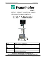
DiPhAS Ultrasound Research Platform
19 August 2011
DiPhAS - Digital Phased Array System
Ultrasound Research Platform
User Manual
Author
Steffen Tretbar, Dr. Holger Hewener
Document identification
DiPhAS -research platform, DiPhAS 64 GPU 3d, Manual
Document number.: B7-0-01-01
Date
18.08.2011
Version
3.0
Document management:
Released and approved by: Hewener at: 18.08.2011
Distribution to: all DiPhAS Users
This document is distributed to the above listed people only.
This document contains project confidential information and must be treated as such.
FhG/ IBMT
Page 1 of 49
Document Nr.: B7-0-01-01
DiPhAS Ultrasound Research Platform
19 August 2011
Dear user,
this manual describes the usage of the experimental ultrasound research system DiPhAS.
The system may only be used by trained personal based on the information included in this manual. The users must have knowledge of ultrasound imaging
and must be trained in using ultrasound devices.
This manual is part of the ultrasound research platform.
To avoid damage to users please ensure that the safety guidelines of this manual are fulfilled.
Thank you
Sincerely
Fraunhofer IBMT
1
Document history
Date:
26.10.2009
20.07.2011
18.08.2011
FhG/ IBMT
Version:
1.0
2.0
3.0
Applies to
page(s):
All
All
All
Reason / modification:
First version
Added information
Added information about cart, included software
documentation, Translation
Page 2 of 49
Document Nr.: B7-0-01-01
DiPhAS Ultrasound Research Platform
2
19 August 2011
Content
1
DOCUMENT HISTORY ................................................................................................................... 2
2
CONTENT ......................................................................................................................................... 3
3
ADDRESS OF DEVELOPER AND MAINTAINER:........................................................................ 5
4
IMPORTANT PRECAUTIONS ........................................................................................................ 6
5
EXPLANATION OF SYMBOLS ...................................................................................................... 7
6
DAMAGE IN TRANSPORTATION ................................................................................................ 8
7
OMISSIONS AND ERRORS ........................................................................................................... 8
8
SAFETY CONSIDERATIONS .......................................................................................................... 8
8.1
8.2
8.3
8.4
8.5
9
HUMAN SAFETY............................................................................................................................. 8
ELECTRICAL SAFETY .................................................................................................................... 9
MECHANICAL SAFETY ................................................................................................................ 11
EMC (ELECTROMAGNETIC COMPATIBILITY) PERFORMANCE ............................................... 12
DATA INTEGRITY / SAFETY ......................................................................................................... 13
RETURNING/SHIPPING PROBES AND REPAIR PARTS ........................................................... 13
10 INFORMATION ABOUT RECYCLING......................................................................................... 13
11 TYPE PLATE ................................................................................................................................... 14
12 SYSTEM DESCRIPTION................................................................................................................ 15
12.1 INTENDED USE: ............................................................................................................................ 15
13 SYSTEM COMPONENTS ............................................................................................................. 16
13.1 HARDWARE ................................................................................................................................. 16
13.2 SOFTWARE .................................................................................................................................. 16
14 ASSEMBLY .................................................................................................................................... 17
14.1 ELECTRICAL INSTALLATION .......................................................................................................... 17
14.2 ULTRASOUND MACHINE SETUP SPACE ......................................................................................... 17
14.3 POST ASSEMBLY INSPECTION ....................................................................................................... 17
14.3.1. ASSEMBLY OF THE DISPLAY AT THE CART ..................................................................................... 17
14.3.2. CONNECTION OF CABLES AT THE BACK OF THE ELECTRONICS UNIT ................................................ 18
14.3.3. CONNECTIONS OF DISPLAY: ........................................................................................................ 18
14.3.4. CONNECTIONS AT THE FRONT OF THE SYSTEM ............................................................................. 19
15 APPLICATION CONDITIONS:...................................................................................................... 20
16 BEGINNING OF OPERATION ...................................................................................................... 21
17 CORRECT USE OF THE DEVICE: ................................................................................................. 21
17.1 POWERING ON THE DEVICE .......................................................................................................... 21
17.2 CONNECTION OF ULTRASOUND TRANSDUCERS ............................................................................ 21
18 MACHINE MAINTENANCE ......................................................................................................... 21
18.1 ELIMINATIONS OF ERRORS ........................................................................................................... 22
18.2 TRAINING OF USERS ..................................................................................................................... 22
19 HAZARD NOTE ............................................................................................................................. 22
20 PERIODIC MAINTENANCE INSPECTIONS ................................................................................ 23
FhG/ IBMT
Page 3 of 49
Document Nr.: B7-0-01-01
DiPhAS Ultrasound Research Platform
19 August 2011
21 SOFTWARE MANUAL USPILOT 4, RECORDING SOFTWARE............................................... 24
21.1 LIST OF FEATURES:....................................................................................................................... 24
21.2 THE MAIN SCREEN ....................................................................................................................... 25
21.3 THE "DEVICE CONTROL" AREA .................................................................................................... 26
21.4 THE "STORED DATA" AREA: PATIENT MANAGEMENT / DATA EXPORT FUNCTIONS .................... 28
21.5 THE "RESEARCH MODE" AREA: ANALYSIS AND CUSTOM FILTERING ........................................... 29
21.6 THE "TRACKING CONTROLLER" AREA: SETTING UP 3D IMAGING ................................................. 30
21.6.1. SETTING UP THE TRACKING PARAMETERS .............................................................................. 30
21.6.2. USING CORRECTION MATRICES .............................................................................................. 31
21.6.3. 3D ACQUISITION COORDINATE SYSTEMS ................................................................................ 32
21.7 USING THE KEYBOARD FOR DEVICE CONTROL: ............................................................................ 34
22 SOFTWARE MANUAL GRB OFFLINE TOOL, ANALYSIS SOFTWARE ................................. 35
22.1 FUNCTIONS OF THE OFFLINE ANALYSIS TOOL:.............................................................................. 35
22.2 THE MAIN SCREEN ....................................................................................................................... 35
22.3 THE MENU BAR ............................................................................................................................ 36
22.3.1. THE EDIT MENU ......................................................................................................................... 37
22.3.2. DATA EXPORT FUNCTIONS .......................................................................................................... 37
22.3.3. THE IMAGE VIEW CONTEXT MENU ............................................................................................... 39
22.4 MEASUREMENTS ......................................................................................................................... 40
22.5 THE PATIENT DATABASE .............................................................................................................. 40
22.6 THE LINE RF DATA DISPLAY.......................................................................................................... 42
22.7 THE PROCESSING DISPLAY ........................................................................................................... 43
22.8 THE CUSTOM FILTER CONTROLS ................................................................................................... 44
22.9 THE KEYBOARD SHORTCUTS OVERVIEW ...................................................................................... 45
22.10 CUSTOM FILTERS ....................................................................................................................... 45
23 APPENDIX A: SPECIFICATION OF DIPHAS-HARDWARE ...................................................... 46
23.1
23.2
23.3
23.4
TRANSMIT HARDWARE: ............................................................................................................... 46
RECEIVE HARDWARE: .................................................................................................................. 46
TRANSDUCER SUPPORT: .............................................................................................................. 46
DATA I/O – INTERFACES, PC ....................................................................................................... 46
24 APPENDIX B: SPECIFICATION OF GRB FILEFORMAT (ULTRASOUND RF DATA) ............. 46
25 APPENDIX C: SPECIFICATION OF B3D FILEFORMAT (ULTRASOUND VOLUME DATA) . 48
FhG/ IBMT
Page 4 of 49
Document Nr.: B7-0-01-01
DiPhAS Ultrasound Research Platform
3
19 August 2011
Address of developer and maintainer:
Fraunhofer Institut für Biomedizinische Technik
Head of Institute:
Prof. Dr. Günter R. Fuhr
Ensheimer Straße 48
66386 St. Ingbert
Contact person:
Dipl.-Ing. (FH) Steffen Tretbar
Division Ultrasound
AG Biomedical Applications and Imaging
Telephone
Telefax
0049 6894/980-226
0049 6894/980-234
E-Mail: [email protected]
Internet: www.ibmt.fraunhofer.de
FhG/ IBMT
Page 5 of 49
Document Nr.: B7-0-01-01
DiPhAS Ultrasound Research Platform
4
19 August 2011
Important Precautions
THIS SERVICE MANUAL IS AVAILABLE IN ENGLISH ONLY.
IF A CUSTOMER’S SERVICE PROVIDER REQUIRES A LANGUAGE OTHER THANENGLISH, IT IS THE
CUSTOMER’S RESPONSIBILITY TO PROVIDE TRANSLATION SERVICES.
DO NOT ATTEMPT TO SERVICE THE EQUIPMENT UNLESS THIS SERVICE MANUAL HAS BEEN
CONSULTED AND IS UNDERSTOOD.
FAILURE TO HEED THIS WARNING MAY RESULT IN INJURY TO THE SERVICE PROVIDER, OPERATOR OR PATIENT FROM ELECTRIC SHOCK, MECHANICAL OR OTHER HAZARDS.
During and after installation, the documentation (i.e. User Manuals, Installation Manuals...) for
the peripheral units must be kept as part of the original system documentation. This will ensure
that all relevant safety and user information is available during the operation and service of the
complete system.
FhG/ IBMT
Page 6 of 49
Document Nr.: B7-0-01-01
DiPhAS Ultrasound Research Platform
5
19 August 2011
Explanation of symbols
Icons and Pictures, or icons, are used wherever they will reinforce the printed message. The
icons, labels and conventions used on the product and in the service information are described
in this chapter.
Various levels of safety precaution messages may be found on the equipment and in the service
information. The different levels of concern are identified by a flag word that precedes the precautionary message. Known or potential hazards are labeled in one of these ways:
„Danger“ is used to indicate the presence of a hazard that will cause severe personal injury or
death if the instructions are ignored
„Warning“ is used to indicate the presence of a hazard that can cause severe personal injury
and property damage if instructions are ignored.
„Caution“ is used to indicate the presence of a hazard that will or can cause minor personal injury and property damage if instructions are ignored.
Notes are used to provide important information about an item or a procedure. Be sure to read
the notes; the information contained in a note can often save you time or effort
The manual of the DiPhAS research platform is available only in English language at the moment.
FhG/ IBMT
Page 7 of 49
Document Nr.: B7-0-01-01
DiPhAS Ultrasound Research Platform
6
19 August 2011
Damage in transportation
All packages should be closely examined at time of delivery. If damage is apparent write “Damage In Shipment” on ALL copies of the freight or express bill BEFORE delivery is accepted or
“signed for” by a representative. Whether noted or concealed, damage MUST be reported to
the carrier immediately upon discovery, or in any event, within 14 days after receipt, and the
contents and containers held for inspection by the carrier. A transportation company will not
pay a claim for damage if an inspection is not requested within this 14 day period.
7
Omissions and errors
If there are any omissions, errors or suggestions for improving this documentation, please contact Fraunhofer IBMT Ultrasound department with specific information listing the system type,
manual title, serial number, page number and suggestion details. Fraunhofer IBMT staff will report all documentation errors or omissions.
8
Safety Considerations
The following safety precautions must be observed during all phases of operation, service and
repair of this equipment. Failure to comply with these precautions or with specific warnings
elsewhere in this manual, violates safety standards of design, manufacture and intended use of
the equipment.
8.1
Human Safety
Operating personnel must not remove the system covers. Servicing should be performed by authorized personnel only. Only personnel who have participated in a DiPhAS seminar are authorized to service the equipment.
Dangerous voltages, capable of causing death, are present in this equipment. Use extreme caution when handling, testing and adjusting.
Only qualified service personnel should remove any covers or panels. Electrical hazards exists at
several points inside. Become thoroughly familiar with all hazard voltages and high current levels
to avoid accidental contact.
Use all Personal Protection Equipment (PPE) such as gloves, safety shoes, safety glasses, and
kneeling pad, to reduce the risk of injury.
FhG/ IBMT
Page 8 of 49
Document Nr.: B7-0-01-01
DiPhAS Ultrasound Research Platform
8.2
19 August 2011
Electrical Safety
Follow these guidelines to minimize shock hazards whenever you are using the DiPhAS platform:
The system is equipped with a three-conductor AC power cable. This must be plugged into an
approved electrical outlet with protective ground. If an extension cord is used with the system,
make sure that the total current rating of the system does not exceed the extension cord rating.
The power outlet used for this equipment should not be shared with other types of equipment.
Both the system power cable and the power connector meet international electrical standards.
A damaged probe can also increase the risk of electric shock if conductive solutions come in
contact with internal live parts. Inspect probes often for cracks or openings in the housing and
holes in and around the acoustic lens or other damage that could allow liquid entry. Become
familiar with the probe's use and care precautions outlined in Probes and Biopsy.
Ultrasound transducers are sensitive instruments which can easily be damaged by rough handling. Take extra care not to drop transducers and avoid contact with sharp or abrasive surfaces.
A damaged housing, lens or cable can result in patient injury or serious impairment or operation.
Ultrasound can produce harmful effects in tissue and potentially result in patient injury. Always
minimize exposure time and keep ultrasound levels low when there is no medical benefit. Use
the principle of ALARA (As Low As Reasonably Achievable), increasing output only when needed
to obtain diagnostic image quality. Observe the acoustic output display and be familiar with all
controls affecting the output level. See the Bioeffects section of the Acoustic Output chapter in
the Advanced Reference Manual for more information.
Do not use with Defibrillator.
This equipment does not have a defibrillator approved applied
part.
FhG/ IBMT
Page 9 of 49
Document Nr.: B7-0-01-01
DiPhAS Ultrasound Research Platform
19 August 2011
This equipment contains dangerous voltages that are capable of serious injury or death. USE EXTREME CAUTION WHEN HANDLING, TESTING AND ADJUSTING.If any defects are observed or
malfunctions occur, stop operating the equipment. Inform a qualified service person and contact
the Fraunhofer Service for information.
There are no user serviceable components inside the console. Refer all servicing to qualified service personnel only.
Only approved and recommended peripherals and accessories should be used. All peripherals
and accessories must be securely connected to the DiPhAS research platform.
Do not substitute parts or modify equipment.
Because of the danger of introducing additional hazards, do not install substitute parts or perform any unauthorized modification of the equipment.
Do not use this equipment if a safety problem is known to exist. Have the unit repaired and performance verified by qualified service personnel before returning to use.
To avoid injury:
•
Do not remove protective covers. No user serviceable parts are inside. Refer service to
qualified service personnel.
•
To assure adequate grounding, connect the attachment plug to a reliable (hospital
grade) grounding outlet.
•
Never use any adaptor or converter of a three-prong-to-two-prong type to connect with
a mains power plug. The protective earth connection will loosen.
•
Do not place liquids on or above the console. Spilled liquid may contact live parts and increase the risk of shock.
Explosion warning
Do not operate the equipment in an explosive atmosphere. Operation of any electrical equipment in such an environment constitutes a definite safety hazard.
FhG/ IBMT
Page 10 of 49
Document Nr.: B7-0-01-01
DiPhAS Ultrasound Research Platform
8.3
19 August 2011
Mechanical Safety
Always lower the LCD before moving the system around.
Keep the heat venting holes of the electronic box unobstructed to avoid overheating of the system.
The system may not be operated by or used on people with cardiac pacemakers! The electromagnetic tracking system emits a strong electromagnetic field that interferes with cardiac pacemakers.
The use of damaged probes or improper use and manipulation of intracavity probes can result in
injury or increased risk of infection. Inspect probes often for sharp, pointed, or rough surface
damage that could cause injury or tear protective barriers. Never use excessive force when manipulating intracavity probes. Become familiar with all instructions and precautions provided
with special purpose probes.
If the unit is very cold or hot, do not turn on its power until it has had a chance to acclimate to
its operating environment.
FhG/ IBMT
Page 11 of 49
Document Nr.: B7-0-01-01
DiPhAS Ultrasound Research Platform
8.4
19 August 2011
EMC (Electromagnetic Compatibility) Performance
All types of electronic equipment may characteristically cause electromagnetic interference with
other equipment, either transmitted through air or connecting cables. The term EMC (Electromagnetic Compatibility) indicates the capability of equipment to curb electromagnetic influence
from other equipment and at the same time not affect other equipment with similar electromagnetic radiation from itself.
Proper installation is required in order to achieve the full EMC performance of the product.
In case of issues related to EMC, please call your service personnel.
Fraunhofer IBMT is not responsible for any interference caused by using other than recommended interconnect cables or by unauthorized changes or modifications to this equipment. Unauthorized changes or modifications could void the users’ authority to operate the equipment.
Do not use devices which intentionally transmit RF signals (cellular phones, transceivers, or radio
controlled products) in the vicinity of this equipment as it may cause performance outside the
published specifications. Keep the power to these type devices turned off when near this
equipment.
Keep power to these devices turned off when near this equipment.
Operating staff in charge of this equipment is required to instruct technicians and other people
who may be around this equipment to fully comply with the above regulation.
The user should never modify this product. User modifications may cause degradation in EMC
performance. Modification of the product includes changes in:
•
Cables (length, material, wiring, etc.)
•
System installation/layout
•
System configuration/components
•
Securing system parts (cover open/close, cover screwing)
Operate the system with all covers closed. If a cover is opened for some reason, be sure to shut
it before starting/resuming operation. Operating the system with any cover open may affect
EMC performance.
FhG/ IBMT
Page 12 of 49
Document Nr.: B7-0-01-01
DiPhAS Ultrasound Research Platform
8.5
19 August 2011
Data integrity / safety
Equipment malfunction or incorrect settings can result in measurement errors or failure to detect
details within the image. The equipment user must become thoroughly familiar with the equipment operation in order to optimize its performance and recognize possible malfunctions. Applications training is available through the Fraunhofer IBMT staff.
DO NOT unplug and/or transport the unit until after the power off sequence has been completed. Failure to do so may result in corrupted measurement files.
Data Integrity Warning:
Archived data is managed in the patient database folder (default: c:\patientdatabase). Performing regular data backup (to any device) is recommended.
9
Returning/Shipping Probes and Repair Parts
Equipment being returned must be clean and free of blood and other infectious substances.
GEMS policy states that body fluids must be properly removed from any part or equipment prior
to shipment. GEMS employees, as well as customers, are responsible for ensuring that
parts/equipment have been properly decontaminated prior to shipment. Under no circumstance
should a part or equipment with visible body fluids be taken or shipped from a clinic or site (for
example an ultrasound probe).
The purpose of the regulation is to protect employees in the transportation industry, as well as
the people who will receive or open this package.
10 Information about recycling
Fraunhofer IBMT recommends to dispose the DiPhAS system economically. In order to recycle
parts or the complete product we can provide additional information. Please contact us for your
recycling options.
FhG/ IBMT
Page 13 of 49
Document Nr.: B7-0-01-01
DiPhAS Ultrasound Research Platform
19 August 2011
11 Type plate
The type plate is located on the back of the DiPhAS electronics unit. To see the detailed full information about your DiPhAS system please refer to the type plate located at your system.
The type plate includes the following information about the DiPhAS system:
•
manufacturer
•
name of the product
•
Serial number
•
Model number
•
year of manufacturing
an example of a DIPhAS type plate
In addition to the device information you will find the service contact information on the right
side of the plate. If you experience any problems using the system please contact the service
hotline stated there.
FhG/ IBMT
Page 14 of 49
Document Nr.: B7-0-01-01
DiPhAS Ultrasound Research Platform
19 August 2011
12 System description
12.1
Intended use:
The ultrasound research platform DiPhAS a system for laboratories and can be used for research
and development.
This system and all its components are an experimental setup and is not tested or certified according to European, international or German medical directives. The system is not a medical
device and may not be used on human being (patients).
To use this system you have to be familiar working with other electrical laboratory devices and
experimental setups. It may only be used by persons trained in using the system by Fraunhofer
IBMT staff members.
Example: DiPhAS without tracking system / front
FhG/ IBMT
Page 15 of 49
Document Nr.: B7-0-01-01
DiPhAS Ultrasound Research Platform
19 August 2011
Example: DiPhAS without tracking system / back
13 System components
The system consists of the hardware and software components described in the following:
13.1
•
•
•
•
•
•
•
13.2
Hardware
Ultrasound system DiPhAS with integrated PC, GPU and 3d tracking system
electromagnetic field generator for 3d tracking system
electromagnetic sensors for ultrasound transducer and pointer
Pointer for 3d tracking system
keyboard
mouse
Cart with insulation transformation
Software
The system has installed a version of the software package "Ultrasound Research Platform
2011" including the components „USPilot4“ and "GRB Offline Analysis Tool". A detailed manual is included later in the manual.
FhG/ IBMT
Page 16 of 49
Document Nr.: B7-0-01-01
DiPhAS Ultrasound Research Platform
19 August 2011
14 Assembly
14.1
Electrical installation
The installation at site and the training of users may only be done be trained persons. This training must be done by Fraunhofer IBMT.
Verify that the scanner is set to the correct voltage. The Voltage settings for the DiPhAS system
is found on a label located near the AC adapter. The default DiPhAS system voltage setting is
220-240VAC.
14.2
Ultrasound machine setup space
For working with ultrasound images it is best to have a dual level lighting room (bright and dim).
Having a bright environment help setting up everything before measurement and switching to a
dim environment improves viewing ultrasound images a lot.
14.3
Post assembly inspection
After installation by the trained personal before the first use you have to ensure the correct installation of the following points:
14.3.1.
Assembly of the display at the cart
Ensure that distance pieces are applied during assembly (see picture)
distance pieces between display and cart
FhG/ IBMT
Page 17 of 49
Document Nr.: B7-0-01-01
DiPhAS Ultrasound Research Platform
14.3.2.
19 August 2011
Connection of cables at the back of the electronics unit
The cables at the system are connected correctly:
• DVI (white) cable attached to extra graphics adapter
• keyboard and mouse 2x USB at any USB connectors
• one of the power cables of the cart to the DiPhAS power connection
• optional Ethernet plug for network integration
14.3.3.
Connections of display:
The display connection (DVI video, power) are made correctly behind the display connector cap:
FhG/ IBMT
Page 18 of 49
Document Nr.: B7-0-01-01
DiPhAS Ultrasound Research Platform
14.3.4.
19 August 2011
Connections at the front of the system
Ultrasound transducer and 3d tracking system are connected correctly:
Transmitter (field generator) to lowest connection at the tracking systems, ultrasound transducer
at left transducer connection, transducer sensor at 3d tracking sensor connector 1 and pointer
at 3d tracking sensor connection 2.
The system may only be used if powered using the integrated power cable of the cart. Only this
way the insulation transformation is used correctly.
FhG/ IBMT
Page 19 of 49
Document Nr.: B7-0-01-01
DiPhAS Ultrasound Research Platform
15
19 August 2011
Application conditions:
The system may only be used at room temperatures between +10°C – +40°C.
The system may only be used at relative air humidity between 30 % and 75 %.
The system may only be used at an air pressure between 700hPa – 1060hPa.
These conditions also apply to the transportation and storage of the device!
FhG/ IBMT
Page 20 of 49
Document Nr.: B7-0-01-01
DiPhAS Ultrasound Research Platform
19 August 2011
16 Beginning of operation
Before every use of the system the system itself has to be checked visually for
•
•
•
Dirt
mechanical damages (cables, housing,...)
mechanical damage of ultrasound transducer (cracks,...), Ultrasound transducers
may not be put totally under water
If the visual inspection fails you are not allowed to use the system. Please contact Fraunhofer
IBMT service hotline to check how the system can be repaired to be used again.
17 Correct use of the device:
17.1
Powering on the device
The DiPhAS research platform is powered by the cart using a connection to 220V / 50Hz power
supply. The system can be switched on using the green switch at the bottom right of the cart.
Using this switch all equipment on the cart is powered on and will power up.
After a short time the system is ready to be used when showing a windows desktop with shortcuts to the applications „USPilot4“ and "GRB Offline Tool".
17.2
Connection of ultrasound transducers
Up to three transducers can be attached to the system. The transducer connectors are locked by
turning the lever after insertion of the plug.
The system may not be used without transducers connected.
18 Machine maintenance
The system may only be maintained by staff of Fraunhofer IBMT. The maintenance actions have
to be logged in a maintenance sheet.
The address of the service station is:
Fraunhofer IBMT
Division Ultrasound
Ensheimer Str. 48
66386 St. Ingbert
Germany
Tel.: 0049 6894 – 980200
FhG/ IBMT
Page 21 of 49
Document Nr.: B7-0-01-01
DiPhAS Ultrasound Research Platform
18.1
19 August 2011
Eliminations of errors
.
If errors occur during normal use you are not allowed to use the system before contacting the
service station.
18.2
Training of users
To use this system you have to be familiar working with other electrical laboratory devices and
experimental setups. It may only be used by persons trained in using the system by Fraunhofer
IBMT staff members.
19 Hazard note
1. The system may only be used after training.
2. recycling:
the system DiPhAS must be send back to Fraunhofer IBMT for correct and complete recycling.
3. The system may not be used without transducers
4. The assembly of the system may only be done by trained personal
5. The system may not be used with damaged or open housing
FhG/ IBMT
Page 22 of 49
Document Nr.: B7-0-01-01
DiPhAS Ultrasound Research Platform
19 August 2011
20 Periodic Maintenance Inspections
It has been determined by engineering that the DiPhAS ultrasound research system does not
have any high wear components that fail with use, therefore no Periodic Maintenance InspecInspe
tions are mandatory. Some Customers Quality Assurance Programs may require additional tasks
and or inspections at a different frequency than listed in this manual. Please contact Fraunhofer
IBMT for more information about hardware inspections, quality assurance and software updates.
Service at Indicated Time
Daily
Monthly
Notes
Clean Probes
•*
* or before each use
Clean ECG
•*
* or before each use
Inspect AC Mains Cable
•
Inspect Cables and Connectors
•
Clean Console
•
Clean LCD
•
Mobile Unit Check Weekly
Console Leakage Current
Checks
Annually
Peripheral Leakage Current
Checks
Annually
Surface Probe Leakage Current
Checks
Annually
Endocavity Probe Leakage CurCu
rent Checks
Quarterly or Annually
Measurement Accuracy Checks
Annually
Probe/Phantom Checks
Quarterly or Annually
Table: Customer Care Schedule
Leakage current checks can be performed by Fraunhofer IBMT. Please contact service hotline for
testing possibilities.
FhG/ IBMT
Page 23 of 49
Document
cument Nr.: B7-0-01-01
DiPhAS Ultrasound Research Platform
19 August 2011
21 Software manual USPilot 4, recording software
21.1
List of features:
This software package includes the Ultrasound Research Offline Research Tool (C#) to load and
analyze single or sequence RF-data frames from the hard disc.
Furthermore this tool implements the plug in filter concept and adds the possibility to implement
new filter algorithms in the offline tool.
Functions of the DiPhAS operating system software:
• Automatic detection of connected transducers and selection of one of these transducers
for operation mode
• Selection of excitation pulses (Burst1, Burst3, Burst8 and its variations including different
voltage levels at transducer mid frequency)
• Selection of data mode: Channel Data 16bit RF Data, 16bit RF-Data after Beamforming
or 8bit amplitude data
• Start / Stop /Freeze of operation
• Cineloop function for video recording and playback
• Setting of TGC using (8) sliders
• Usage of TGC-predefines
• Changing recording depth
• Change of focusing (number of focus: 1,2,4, depth and distance between adjacent focus)
• Selection of imaging mode: normal mode, High Speed Mode, Small Mode, High Resolution Mode
• Visualization of scanconverted image
• Visualization of A-Scan (16bit or 8bit) of a measurement line (mouse selectable)
• Selection of pictograms to document the measurement region
• 2B-visualization of a live and a still image to compare different slices
• Storage of screenshots as image data (JPG) and RF-file (GRB with a frame)
• Record of image sequences and playback of stored sequences in cineloop
• Storage of a video as video file (AVI with arbitrary compression and settings) and RF-file
(GRB with several frames)
• Storage as DICOM data set (single image, sequence) (optionally if the DICOM-module is
selected)
• Print of freeze images to your default printer or medical BW-printer (optionally available)
• Usage of external programmable filter algorithms on the basis of image or RF for online
operation
• Parallel visualization of live filtering and of the live-B-image side by side
• File-based patient management in the local system
o Selection of a patient of the patient overview
o Creation of a new patient
o Definition of new studies
o Display of data sets of a study in the form of thumbnails
o Open of data sets after selection in the offline analysis tool
FhG/ IBMT
Page 24 of 49
Document Nr.: B7-0-01-01
DiPhAS Ultrasound Research Platform
21.2
19 August 2011
The main screen
The main screen is divided in different party for device control and visualization of information
or measured data.
The bottom third of the screen is used for menus like the device control, stored data view or additional research mode information. The user can change between these menus using the
"menu selection" combo box on the left side or by using the keyboard F-shortcuts (described
below in section "using the keyboard for device control").
The top area is for visualization of system parameters and measured scanconverted data in image representation. On the top left general information about a selected patient or subject is
displayed including the full name, gender and birth date. The middle area shows the image representation of the scanned area in brightness mode. A TGC indicating line, the focus setting
using a white arrow and distance markers (a circle every cm, a white rectangle for every 5cm)
are displayed on the left side of the image. On the right next to the scanning image there is a
greymap representing the currently used mapping. The transducer information including the
scanning settings is displayed on the right side of the window ("scan information") and below it
there are two images visualizing the used excitation and scanning region as pictograms in the
"graphical information area".
On the bottom of the screen below the "menu area" there are additional information about the
system operating status ("status output"), software version ("device version information") and
the current date and time.
FhG/ IBMT
Page 25 of 49
Document Nr.: B7-0-01-01
DiPhAS Ultrasound Research Platform
21.3
19 August 2011
The "device control" area
The device control area allows parameterization of the scanning and preset usage. The system
detects the attached transducers at runtime and presents detected and known transducers in
the "transducer list" using its qualified unique name. If only one transducer is attached to the
system the systems starts using this transducer by default. If more transducers or transducer
apertures are detected the user has to select the transducer first and starts scanning with the
button "set”.
The presets found for the transducer highlighted in the transducer list are shown in the "preset
selection" combo box. These presets are stored in the preset folder (default: "c:\presets") and if
there is a preset available for the selected transducer the first preset found is used as starting parameter values. Changing the selection of this preset combo box will stop the system and start it
again with the values defined by the newly selected preset.
To store a new preset using the currently selected scanning parameters click on the "preset selection" combo box with the right mouse button, enter a name in the appearing context menu
for the preset and click on the "save" button below the name input with the left mouse button
to create a preset setting file with the current settings in the preset folder.
The "Data Mode" combo box lets you select between 8bit amplitude data acquisition, 16 bit RF
data acquisition and single element channel data acquisition. Please refer to the DiPhAS SDK
Reference Manual for more information about the acquisition modes.
The "TGC controls" are used to the systems receiving time dependent (this way depth dependent) amplification of measured data. The 8 sliders range from 0db up to 40 db but an overall
gain with additional 0db up to 40 db is available in the middle of the "device control" area.
Using the buttons ("+" and "-") on top of the TGC slider array you can switch between several
predefined TGC settings including linear increasing and constant gain.
Using the "imaging settings" combo box you can select the imaging mode in a selection of image size and line density. You can choose of "normal", "highres" (double line density), "small"
(limited field of view) and "highspeed" (normal view area but with half the line density). Changing this value will cause the system to pause loading the new settings before restarting again.
The values of recording depth and voltage are dependent of the maximum settings specified for
the current transducer and can be changed by dragging the sliders. The focus position can be
changed to different depths; and the number of focus points can be selected of 1, 2 or 4 focus
points. The focus distance can be adjusted using the slider between the focus position and focus
count.
Using the persistence feature below the focusing settings the signal can be improved by averaging up to 10 frames over time. Note that the result is more blurry caused by the averaging of
FhG/ IBMT
Page 26 of 49
Document Nr.: B7-0-01-01
DiPhAS Ultrasound Research Platform
19 August 2011
echoes over time but a high persistence value can eliminate system noise on static measurements without movement.
In the middle is the "freeze (pause)" button to pause the systems recording for further in detail
viewing or analysis. If the system is paused a trackbar slider will appear over the freeze button
that allows rewinding the last recorded frames as a cineloop. Single frames of this cineloop can
be stored separately or the complete cineloop can be stored using the appearing "store video"
button next to the "save current" button. The video data stored ranges from the trackbar position to the right of the slider if the trackbar is pulled back in time. If the slider is in default position (most right) after freezing the image then the complete cineloop is stored in the patient’s
data.
The "print current" buttons outputs the current displayed image on the default printer of the
system (if attached).
Using the "excitation selection menu" and the "pictogram selection menu" you can specify the
region investigated and change the excitation pulse:
The "patient selection menu" opens the patient list overview that can be used to select an existing or create a new patient data record. These patient data records are stored file based on the
hard disc as JPG images (low compression) and RF data files (GRB) and managed by several XML
files. Default location for the patient database is "c:\ patientdatabase". To reset the database
you can delete the complete content of this directory to start with an empty database.
The patient list dialog contains a grid of available already created patients on top including information about birth date and number of stored data sets. To select an existing patient just use
the "select" button on the last column of the patient data or confirm your selection by pressing
"return" after selecting the patient record using the cursor keys.
To create a new patient record use the button on the bottom right of the dialog overlay and the
"add new patient dialog" opens.
Patient names
Stored data
Patient selection
Full name field
Add new
Patient
Gender selection
Birth date
Additional comments
Cancel
FhG/ IBMT
Confirmation
Page 27 of 49
Document Nr.: B7-0-01-01
DiPhAS Ultrasound Research Platform
21.4
19 August 2011
The "stored data" area: Patient Management / Data export functions
Add a new study
Save current
screenshot
Open selected
dataset for
analysis
Current study
Data display area
Stored dataset
Stored dataset
Selected for analysis
When no patient is selected yet the "patient list selection" dialog will be opened before stored
data is displayed.
If a patient is selected the stored data area shows a combo box with all available studies for this
patient in the "current study" combo box and all available data sets (stills and videos) for the
currently selected study below it in the "data display area".
To add a new study use the "add a new study" button and an additional text input and buttons
appears next to it:
Entering a new study name and confirming it with the button next to it will create a new subfolder as study and select it automatically.
To store a current still image you can use the "save current screenshot" button over the "data
display area", the "save image" button on the "device control" area or the "Print"-Button (see
F-keys in a later chapter).
To open a dataset for analysis select a stored dataset with the left mouse button and click the
"open selected dataset for analysis" button on the top right of the stored data menu. The offline analysis tool opens with the selected dataset and is displayed in the top area where the live
scanning system images were displayed. The analysis overlay can be closed using the small red
button on the top left of the displayed scanconverted image.
FhG/ IBMT
Page 28 of 49
Document Nr.: B7-0-01-01
DiPhAS Ultrasound Research Platform
19 August 2011
Close offline analysis to return to
live measurement system
Open selected
dataset for
analysis
Stored dataset
Selected for analysis
For more information about the usage of the ultrasound research offline analysis tool please refer to the "Ultrasound Research Analysis Tool Manual".
21.5
The "research mode" area: Analysis and Custom Filtering
Indicator if
selection is shown
in B-Image
Line selection
Scale settings (A-Scan)
Custom filter
selection
Information about
selected custom filter
„dual“ live view
Windowing of A-Scan
by red cursors
A-Scan of
selected line
Spectrum of selected line (limited to
window by red cursors)
Custom filter visualization area
The research mode shows the A-Scan line of a selectable line in 8bit amplitude or 16bit RF data
mode according to the selected operation mode. The scale of the x-axis of the A-Scan can be
changed from "Meters" to "Seconds" or "Samples" for better interpretation of the recorded
data.
The amplitude shown will initially adapt to amplitude or RF data default values but can be
changed by clicking on the range minimal and maximum values and entering a new desired value. A double click will reset the values to default again. Zooming in the A-Scan window can be
done by holding the shift key and drawing an area in the graph that should be zoomed out. Using these controls all aspects of recorded data can be viewed in overall and in depth.
Below the A-Scan display there is a spectral plot of a signal segment selected by the red cursors
windowing the signal in the A-Scan-Display. The range editing and zooming options are here
the same as described above for the A-Scan display. Furthermore the red cursor in the spectral
plot can be used to select positions in plotted data to see exact frequency values plotted next
the cursor.
Using custom filters can be done on the bottom right of the main window. There is an area for
custom filter management (selection and additional information) and below it an area for the
actual filter to be displayed and parameterized.
Using the combo box one filter can be selected of the found filter classes implementing the IFIlterDlg interface in the application folder. Any *.dll and *.exe .NET assembly will be searched for
suitable implementations and added to the combo box. Selecting a filter in the combo box will
FhG/ IBMT
Page 29 of 49
Document Nr.: B7-0-01-01
DiPhAS Ultrasound Research Platform
19 August 2011
show the filter window below it and allows the parameterization of each filter using for
processing.
When a filter is applied to incoming measurement data the "dual live view" button can be used
to visualize both the unfiltered and the filtered image representation in parallel (see cover image
of this document).
21.6
The "tracking controller" area: Setting up 3d imaging
This area can be selected as 4th entry of the dropdown menu and represents the setup of attached tracking systems. The research platform supports the electromagnetic tracking system
driveBay or trackstar by Ascension and the optical tracking system Polaris and Spectra made by
NDI (Northern Digital Inc).
21.6.1.
Setting up the tracking parameters
After pressing initialize the status LED at the front of the driveBay system will change to solid
orange for a short time. The UI will not be responsive for a while (approx. 8 seconds) until the
initialization is finished.
After the initialization the sensors to be read can be enabled by checking the "enabled" checkbox. The first sensor is enabled as default. Additional sensors can be enabled manually.
Sensor ports that have no sensor attached to and are enabled will return an invalid matrix filled
with 0's.
FhG/ IBMT
Page 30 of 49
Document Nr.: B7-0-01-01
DiPhAS Ultrasound Research Platform
19 August 2011
Pressing the green start button will start the position acquisition. The position of the first sensor
will automatically be included in the rf data stored by the USPilot 4 software in the cineloop buffer or written to disc if stored. The data of any sensor can also be written to disc using the "select file" button in the trackers groupbox first and specifying an output file. After this each press
on the "save current position to file" button will append the current position matrix row after
row in the specified textfile.
21.6.2.
Using correction matrices
It is possible to use a second sensor as reference sensor and store all position information with
reference to the second sensor. To do so you can select the reference coordinate system for
each sensor to be the world (the transmitter) or one of the other sensors.
To use a static correction matrix to compensate the shift (and even rotation) between the sensor
position at the transducer and the image plane imaged by the transducer you can input a correction matrix after hitting the "edit" button next to the "correction matrix" checkbox. The
TrackingCorrectionEditor appears:
FhG/ IBMT
Page 31 of 49
Document Nr.: B7-0-01-01
DiPhAS Ultrasound Research Platform
19 August 2011
You can enter a correction matrix by hand or import a previous entered matrix by using the
"import" button.
imported correction matrix
To use the correction matrix just check the "correction matrix" checkbox next to the "edit" button and you'll see the position data changing according to this correction.
21.6.3.
3d acquisition coordinate systems
The coordinate system of the electromagnetic tracking has its origin at the transmitter.
The origin of the short and mid-range transmitters’ default Reference Frame is an approximate
location at the center of the transmitter’s coil set.
FhG/ IBMT
Page 32 of 49
Document Nr.: B7-0-01-01
DiPhAS Ultrasound Research Platform
19 August 2011
The system provides a homogenous transformation matrix in the following working area:
Measurement using the top hemisphere
Dimensions in each axis for the mid-range transmitter are:
Z = 20 to 66cm from the transmitter center
Y = ±28 cm from the transmitter center
X = ±30 cm from the transmitter center
The DiPhAS system works in the front hemisphere of the tracking system. This means that the
tracking is correct on top (above) of the transmitter if the transducer is put upright on a table
The electromagnetic tracking system still is sensitive to magnetic and metal structures. You have
to ensure that no metal structures are in direct contact with the transmitter or the sensors in order to get good tracking results.
FhG/ IBMT
Page 33 of 49
Document Nr.: B7-0-01-01
DiPhAS Ultrasound Research Platform
21.7
19 August 2011
Using the keyboard for device control:
It is possible to use the keyboard for common commands like data storage or patient selection.
A graphical shortcut visualization is included in with the software that can be used above the
function keys (F-keys). The image printed with a size of 360x30mm fits perfectly over the function keys of a common "Cherry"-keyboard:
Using the checkbox "use keys" in the "device control" section these shortcuts are translated in
the described functions:
Command
quits the application
opens the "device control" in the menu area
opens the "stored data" in the menu area
opens the "research mode" in the menu area
opens the "patient selection menu" as dialog overlay
stores the current frame as still image in current selected study
stores the cinebuffer as video data in current selected study
opens the "excitation selection dialog" as overlay
opens the "pictogram (region) selection dialog" as overlay
decreases the recording depth
increases the recording depth
decreases the overall gain
increases the overall gain
prints the current frame on the default printer installed in the windows system
changes the acquisition mode from 8bit to 16bit or vice versa
freezes or unfreezes the data acquisition(pause/unpause)
Shortcut
Escape (Esc)
F1
F2
F3
F4
F5
F6
F7
F8
F9
F10
F11
F12
Print Screen
Scroll
Pause
In research mode the keyboard focus is initially at the line selection trackbar and you can change
the selection using the cursor keys on the keyboard directly. Pressing the space bar here will
toggle the selected line display in the B-Mode display.
When selecting the excitation pulse or the pictogram you can use the cursors and the return key
to select an icon without having to take the mouse.
FhG/ IBMT
Page 34 of 49
Document Nr.: B7-0-01-01
DiPhAS Ultrasound Research Platform
19 August 2011
22 Software manual GRB Offline Tool, Analysis
Analys software
22.1
•
•
•
•
•
•
•
•
•
•
•
•
•
•
•
•
•
•
Functions of the offline analysis tool:
Load RF files from hard disc (RF screenshots and RF videos)
Selection of single frames of RF-videos
RF
Playback of RF-data
data as video
Display of device parameters (transducer geometry, beamforming parameters, 3d3d
Tracking positions) as text
Display of Scan-converted
converted image
Measurement of distances and areas in B-image
B
Display of single A-scans
scans (16bit RF, 15bit envelope data or 8bit amplitude data selectaselect
ble) of a single ultrasound line out of all B-Mode
B
lines
Zoom and offset in B-Image
Image-display
Selection of „Region of Interest“ in A-scan
A
using 4 cursors
Selection of „Region of Interest“ in B-scan
B
using the mouse
User defined filtering (DLL imported) of measured data with respect to ROIs
Displaying of filtered A--Scans (16bit or 8bit) of selected line
Zoom -Function in A-Scan
Scan-Display
Display of signal spectrum of selected A-Scan
A Scan and display of maximum frequency, midmi
frequency and bandwidth for further filtering
Display of selected A-Scan
Scan line in scan converted B-image
B
Export of line data as text
text data for external programs, as DICOM File, as 3D reconreco
structed File (required 3D position data)
Export of A-scan
scan diagrams as GNUPlot and image file
Browsing a local file based patient database and opening its content
This software uses keyboard shortcuts a lot to speed up the user experience. Please refer to the
keyboard shortcut below to see a full shortcut list.
22.2
The main screen
The Ultrasound Research Analysis Software consists mainly of one window displaying the ultraultr
sound data as image and signals.
gnals. You can see the main window here:
1 The main window including processing visualization
FhG/ IBMT
Page 35 of 49
Document
cument Nr.: B7-0-01-01
DiPhAS Ultrasound Research Platform
19 August 2011
This window will be opened if you start the application using the application shortcut on your
desktop or the start menu and loading an rf data file (ctrl + o). If you start the software by
double-clicking an *.grb rf data file you will start in the same window in "image view mode":
2 The main window in image view mode including playback controls
You can toggle between these mode using the "show/hide processing and filters" (ctrl + f) entry
in the “view” submenu.
To begin analyzing a rf data file you have to load it using the "open RF data" entry in the “file”
submenu in the menu bar and selecting the *.grb file in the open file dialog. The loaded rf data
is displayed using the scan conversion suiting the data representation of the file and one line of
the data (A-Scan) is displayed on the top right if extended view mode is used. The spectrum of a
selected window area is displayed below in the line data spectrum plot.
In GRB rf data files with more frames inside a file the current frame to be displayed and
processed can be selected using the "rf data file frame selection" slider under the image display
area and the corresponding frame will be loaded as soon the slider gets moved. The current
frame number and the rf data filename is displayed at the bottom of the application window.
Using the "frame playback toggle" button next to the "rf data file frame selection" slider (ctrl +
space) all frames in the currently loaded file can be played at a frame rate of approx. 20 Hz. This
represents a cineloop function. The playback auto repeat function can be toggled in the view
menu or by the shortcut ctrl + l (for “loop”). Looping is on by default. The brightness and contrast of the frame display can be adjusted if the loaded data is stored as 16 bit or 32 bit data
(see DiPhAS SDK Reference Manual for more details). 8 bit amplitude data is already stored after
logarithmic compression and only the general greylevel can be adjusted using the right "leveling" slider of the "display brightness setup". Gain and brightness can also be charged using the
mouse movement with ctrl + clicked left mouse button and moving the mouse horizontal
(brightness) or vertical (gain).
22.3
The menu bar
The menu bar contains five different submenus. The “File” entry provides open, save, print and
export functions. By using functions of the “edit” submenu, the actual rf file can be edited in
different ways, for example by inserting data of another rf file into the current loaded file at a
certain position. The “View” section includes functions to control the view of the program like
hide or show options and playback functions. The “Options” submenu comprises a function to
FhG/ IBMT
Page 36 of 49
Document Nr.: B7-0-01-01
DiPhAS Ultrasound Research Platform
19 August 2011
change the path of the patient database and the “About” shows software information and
point to the IBMT homepage.
3 Menu bar in the main window in extended image view mode
22.3.1.
The edit menu
4 The main window in the extended view mode with the edit menu
Data export functions
Using the data export functionality in the file menu you can export a single screenshot as image
file (standard JPG image file without compression
compression for good image quality). You might change
the image display components (drawing scale, ...). See below for more information about disabldisab
ing view elements in the B-scan.
scan. You can also use the ctrl + s shortcut to save the current B-scan
B
view.
"Print output
ut image” to medical printer in the “file” submenu will output the image seen in the
image display area to the default printer installed in the system. This option can be used on
standard medical printing devices for documentation but general office printers
printe can also be used
to output just the image on prints.
22.3.2.
Other export functions can be selected in the menubar under “File
FhG/ IBMT
Export”:
Page 37 of 49
Document
cument Nr.: B7-0-01-01
DiPhAS Ultrasound Research Platform
19 August 2011
5 The main window in image view mode with the export functions
The “export 3D reconstruction” function exports the complete rf file as reconstructed 3D file.
The volume will be stored in b3d-format and additional reconstruction parameters can be adjusted. The “export 3d position only” option creates an “Amira point cluster” including just the
frame boundary positions. For detailed information about 3d imaging please refer to the “3d ultrasound framework”-manual.
The “export current frame as textfile” exports the current displayed frame as textfile for using it
in external programs.
The “export current frame as DICOM still” function exports only the content of the current displayed frame in a DICOM standard file as ultrasound still image data.
The data can be stored in DICOM format in different file formats:
The "export complete rf file as DICOM series" function exports the content of the loaded rf data
file in DICOM standard writing a time series of all frames (DICOM video data / time series with
ultrasound image modality).
The “export complete rf file as DICOM volume” function exports the content of the loaded rf
data file in a DICOM standard writing all frames as volume slices with slice thickness based on yposition change between slice 0 and slice 1. If no 3d data is available, the in-slice-pitch is used as
3d slice thickness.
"Export complete rf file as image sequence" writes a set of image files to disc (*.jpg) generating
an image file for every frame in the rf data file. The image file are numbered with its corresponding GRB slice number.
"Frame subset into new rf file" opens a small dialog window to edit the subset of frames to be
exported into another rf data file (*.grb):
6 frame subset into new rf file window
The number of the first and last frame to be extracted can be entered here and a click to the
"compute frame extraction" button will write a new rf data file to disc including the selected
data subset. This can be used to extract a sequence of interest into a new file.
FhG/ IBMT
Page 38 of 49
Document Nr.: B7-0-01-01
DiPhAS Ultrasound Research Platform
19 August 2011
The “export complete rf file as AVI video” exports the current loaded rf file in an AVI video file.
A window will open to select one of the systems video codecs.
The “export current frame after filter processing” function exports the current displayed frame
as JPG file, after applying the filtering processing as setup.
The “export complete rf file after filter processing” function applies the filtering processing as
set up to all slices of the loaded GRB file and stores the result in a new GRB file with the same
number of slices, after a filtering process.
The “export complete rf file with different header” export the complete rf file with a edited
header in a new rf file. This way errors in the parameters of recorded data can by inputting correct values in the shown header editor before storage.
The image view context menu
Clicking on the “View” entry in the menu bar a submenu will be shown with additional image
display settings:
22.3.3.
7 The main window in image view mode with the view menu
The first two mean points change the dialog window size to include/exclude the A-scan,
processing and filtering display (on the right side, it shown) and to show/hide the patient database on the bottom of the fully extended dialog window. The playback menu item triggers the
same sequence playback as the “frame playback toggle”-button under the B-scan display. If this
element is checked multiple frames (slices) inside one rf data file are loaded and visualized as a
sequence.
The “loop” playback” menu item indicates that the playback will start again with the first slice
of the file, if the item is checked. The “show/hide scan information” element enables the visualization of the selected line in the B-Mode image.
The "normal" display mode is default and displays the common scale and information in the
display. Using the "show uniformity" option you will see an additional display presenting the
homogeneity of measurements regarding an image sequence in order to determine the quality
of a ultrasound transducer and system. Please contact us for additional information about image
quality measurement.
FhG/ IBMT
Page 39 of 49
Document Nr.: B7-0-01-01
DiPhAS Ultrasound Research Platform
19 August 2011
8 The main window in image view mode with uniformity computation
22.4
Measurements
The user can make measurements of distances at any time by holding down the shift button and
dragging a line while having the left mouse button pressed.
The system will visualize the line measured between the beginning and the end and will output
the distance in millimeters next to the cursor position:
9 The main window in image view mode with measurement of distances in the image
22.5
The patient database
By using the “show database” option in the view submenu, the graphical user interface is exe
tended at the bottom by the patient data browser.
FhG/ IBMT
Page 40 of 49
Document
cument Nr.: B7-0-01-01
DiPhAS Ultrasound Research Platform
19 August 2011
10 The main window in extended view mode with the patient datbase window
A patient can be selected by using the “select patient button”. The “patient list from database”
window is opening. The patient list shows the different patients of the database with additional
information like birth date, number of studies, etc. There is the option to select all patients by
using the “select all” button or select one patient by using the “open” button. Using the “delete selected” button, every patient selected by using the correspondent check box in the list is
deleted from the patient database.
11 The patient list from database window
The browser contains information to the patient, different data sets and the name of the study.
If there is more than one study, the user can choose a study from the drop-down list. By using
the “+” button, a new study can be add to patient and can be filled with data afterwards.
Double click of the left mouse button on a data set opens the selected data set in the main
screen.
FhG/ IBMT
Page 41 of 49
Document Nr.: B7-0-01-01
DiPhAS Ultrasound Research Platform
22.6
19 August 2011
The line rf data display
If you use "show processing and filters" mode the top right shows an "A-Scan" displaying a
single line from the data frame in the "rf line data display" area.
12 The main window in extended image view mode
You can select witch single line is displayed by using the "line selection slider" under the graph
itself. The rf line data display will refresh automatically when dragging the slider to a new line.
The line position information displays the position of the physical start point of each line and the
direction vector the line and therefore the mechanical ultrasound wave is propagating. The values are referenced to a local in-frame coordinate system that usually has its origin at the starting
point of the middle line (linear or phased transducer) or at the center of the curved circle regarding the radius of the transducer (convex transducer).
Using the right mouse button on the "rf line data display" shows the context menu with additional settings for the data visualization:
13 The main window in extended image view mode with the RF line data context menu
FhG/ IBMT
Page 42 of 49
Document Nr.: B7-0-01-01
DiPhAS Ultrasound Research Platform
19 August 2011
The "show selection in B-Image" can be checked to display a white marked line in the left "scan
converted data displayed as image"-area showing the line selection done using the "line selection slider".
The two options "show original data line" and "show processed data line" can be checked to
see the input data line in green and the processed data (if available after custom filtering) in
purple in the "rf line data display" graph.
Furthermore you can adjust how the data will be displayed. Using a data file recorded as 16 bit
RAW data you can choose between 16 bit raw data display with high dynamic, 15 bit data after
envelope computation and 8 bit amplitude data after logarithmic compression and you can
change the unit for the graphs between samples, time[µs] and depth[mm]. In addition, there is a
auto fit mode of the cursor to the graphs.
The graph content can be stored to hard disc as image file as seen on screen or as a set of values in GNU plot format for additional plotting possibilities.
22.7
The processing display
Using the "image histogram"-selection in the line data spectrum view a grey value histogram is
shown in the scan converted image giving information about the homogeneity of grey levels in a
single image.
14 The main window in extended view mode with a image histogram
Under the "rf line data display" is a spectral analysis of the current A-Scan signal plotted in the
"line data spectrum" area. Considering the samplerate of the recorded signal and the window
defined by the blue cursors in the "rf line data display" this plot shows the spectrum of the selected area.
Holding the left mouse key a region of interest can be zoomed for visualization. Drag a window
with pressed left mouse button to zoom in that selected area. Reset zoom by double clicking the
left mouse button on the data graph to view the full signal again.
FhG/ IBMT
Page 43 of 49
Document Nr.: B7-0-01-01
DiPhAS Ultrasound Research Platform
19 August 2011
Using the right mouse button on the plotting area the context menu shows additional options
like resetting the width of the display area after zooming or changing auto scaling behavior of
the spectrum amplitude axis.
There is the possibility to auto detect maximal frequency contents and signal bandwidth in a selected signal subset by checking the "auto detect max, mid and bandwidth freq" option.
15 The main window in extended view mode with RF line dat spectrum context menu
The selection done by the frequency cursors can be used for bandpass filtering of the signal. On
the other hand the auto detection of selected parameters can be turned off and a fix bandpass
can be selected and applied to all incoming signals.
The graph content can be stored to hard disc as image file as seen on screen or as a set of values in GNU plot format for additional plotting possibilities.
22.8
The custom filter controls
Using custom filters can be done on the bottom right of the main window. There is an area for
custom filter management (adding, removing, ordering) and an area for the actual filter to be
displayed and parameterized.
The custom filters that are integrated in the system can be added here to the processing chain.
For more information about custom filter development please refer to the chapter "custom filters".
FhG/ IBMT
Page 44 of 49
Document Nr.: B7-0-01-01
DiPhAS Ultrasound Research Platform
19 August 2011
16 The main window in extended view mode with processing filter panel
Using the "+" button a combo box is displayed with the possibility to select one of the found filter classes implementing the IFIlterDlg interface in the application folder. Any *.dll and *.exe
.NET assembly will be searched for suitable implementations and added to the combo box. Using "select" to add the filter to the processing chain will insert an entry in the list box on the
main window. If there are more filters added to the list then the order can be changed by using
the "Filter order change" buttons to move a filter up/down. Selecting a filter in the list box will
show the filter window on the right and allows the parameterization of each filter using for
processing.
22.9
The keyboard shortcuts overview
Command
Open RF data
Print output image
Save output image
Show/hide processing and filters
Show / hide patient database
Playback RF data sequence
Loop playback
Show/hide scan information
Change gain
Change brightness
Measure distance in image
22.10
Shortcut
Ctrl + O
Ctrl + P
Ctrl + S
Ctrl + F
Ctrl + D
Ctrl + Space
Ctrl + L
Ctrl + I
Ctrl + left mouse key (hold) + move mouse
(horizontal) in B-scan image display
Ctrl + left mouse key (hold) + move mouse
(vertical) in B-scan image display
Shift + left mouse key (hold) + drag to end
point of measurement
Custom Filters
This chapter will be included in a future release. Please contact us directly for more information.
FhG/ IBMT
Page 45 of 49
Document Nr.: B7-0-01-01
DiPhAS Ultrasound Research Platform
19 August 2011
23 Appendix A: Specification of DiPhAS-Hardware
23.1
Transmit hardware:
Number of transmit channels:
64
Max. Output voltage:
120 Vpp (50 Ohm)
Max. Output current (peak-peak):
0.4 A
Transmit pulse Form:
rectangular bipolar Burst1, Burst3 und Burst8
Digitalization resolution:
8.3 ns
Number of output voltage steps:
5
Minimal Beamforming delay resolution:
8.3 ns
Max midfrequency of transducers:
10 MHz
Number of transmit focus:
4
23.2
Receive Hardware:
Number of receive channels:
64
Input bandwidth (-6 dB)
10 MHz
Analog Gain
42 dB
fix Gain:
12 dB
dyn.TGC:
30 dB
Digital Gain:
40 dB
A/D conversion
:
12 Bit, 40 MHz per channel
Max recording depth:
20 cm
23.3
Transducer support:
Types: phased, curved, linear, custom transducer with known geometry, pitch and transducer pin out
Number of transducer connectors: 2
Number of channels per connector 64
The pin out of ultrasound transducers is predefined by IBMT and can be adapted to other ultrasound transducers using separate connector adaptors.
23.4
Data I/O – Interfaces, PC
The system uses a High-Speed USB 2.0-connection for data acquisition and programming and is
connected to a PC with Mini ITX form factor. It uses 4GByte main memory and a Core 2 Quad
processor with a 128 GByte solid state disc drive for data storage and the Windows 7 (64bit)
operating system.
24 Appendix B: Specification of GRB fileformat (ultrasound rf data)
Internal version number : 3.1
One GRB File contains one or more frames consisting of the following data (in binary format):
(Geometry data)
FhG/ IBMT
Page 46 of 49
Document Nr.: B7-0-01-01
DiPhAS Ultrasound Research Platform
Int
50 bytes
--14 bytes
int
int
int
float
float
19 August 2011
fixed id: “8199”
desc: "`Calibration2 Data (new)%\0\0...\0"
Transducer Name in char's
transducer type
1 Linear, 2 curved
number of lines
number of samples per line
samplerate (in Hz)
mm per sample
for each of the n line:
float
x-Position of Line in mm
float
y-Position of Line in mm (linear = 0)
float
z-Position of Line in mm (linear = 0)
float
float
float
(global position data)
Int
60 bytes
Float
3* float
3* float
3* float
3* float
direction of line x-component
direction of line y-component
direction of line z-component
fixed id: „8193”
empty string of length 60 characters
focusing position in millimeters for mechanical focusing systems
Cartesian coordinate system of frame origin
1. column of rotation matrix
2. column of rotation matrix
3. column of rotation matrix
(additional information)
8* Byte
Byte
4* Byte
7 Byte
8 TGC values (each: Byte [0 ;80])
voltage (in V)
4 focus positions (in mm 'max. 256mm)
unused
Int
fixed id: „5”
float
float
float
mid frequency of excitation (in Hz)
burst length (in cycles)
scaling factor for amplitudes
30 bytes
patient name (max. 30 char's)
Byte
Byte
Byte
Byte
Pictogram-ID
Pixel X-Position of Pictogram [0;70]
Pixel Y-Position of Pictogram [0;70]
Angle of Pictogram [0;180]
26 bytes
not used yet
FhG/ IBMT
Page 47 of 49
Document Nr.: B7-0-01-01
DiPhAS Ultrasound Research Platform
(ultrasound rf data)
Int
64 bytes
--int
int
int
n bytes
19 August 2011
fixed id: “12289”
desc: "`BScan Data%\0\0...\0"
number of points
number of lines
Bytes Per Point (1 for 8bit, 2 for 16bit, 4 for 32bit)
Ultrasound-Data (8bit Bytes, 16bit signed short, 32bit signed float)
n= points*lines*bpp
(timestamp)
Int
fixed id: “5”
64 bytes
desc: "`TimeStamp%\0\0...\0"
--unsigned int64 TimeStamp
GRB files with multiple frames simply attach one frame after another in binary format on hard
disc.
All variable sizes are 32bit system sizes
25 Appendix C: Specification of b3d fileformat (ultrasound volume data)
One dataset (Volume) consists of two blocks in the following order:
general volume data information
volume data
The single blocks consist of:
general volume data information:
100 unsigned byte
Volume desciption (comment)
64 bytes
desc: "Calibration2 Data (new)\0\0...\0"
8 byte double measurement of volume in x [mm]
8 byte double measurement of volume in y [mm]
8 byte double measurement of volume in z [mm]
Reference matrix of volume in column order
8 byte double reference[0][0]
8 byte double reference[1][0]
8 byte double reference[2][0]
8 byte double reference[0][1]
8 byte double reference[1][1]
8 byte double reference[2][1]
8 byte double reference[0][2]
8 byte double reference[1][2]
8 byte double reference[2][2]
FhG/ IBMT
Page 48 of 49
Document Nr.: B7-0-01-01
DiPhAS Ultrasound Research Platform
19 August 2011
8 byte double reference[0][3]
8 byte double reference[1][3]
8 byte double reference[2][3]
8 byte double number of voxels of volume in x
8 byte double number of voxels of volume in x
8 byte double number of voxels of volume in x
volume data block :
n bytes unsigned
8-Bit Voxeldaten (x-Komponente fastest)
n=dim.x*dim.y*dim.z
FhG/ IBMT
Page 49 of 49
Document Nr.: B7-0-01-01