1
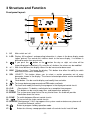
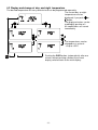
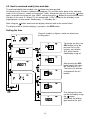
ThermoControl Plus M1
2-stage or modulating controller
with one control zone
(alternative: two control zone 1-stage)
Operating and
Installation Manual
Schwank Ltd. – 62 Sunningdale Road – Sutton, Surrey SM1 2JS
Tel: +44 (0)208- 641 3900 Fax: +44 (0)208- 641 2594
E-mail: [email protected]
Internet: www.schwank.co.uk
Subject to technical changes. Version 01/12
Content:
1 INTRODUCTION ................................................................................................. 3
2 YOUR SAFETY ................................................................................................... 4
3 STRUCTURE AND FUNCTION .......................................................................... 5
4 OPERATION ....................................................................................................... 6
4.1 Basic knowledge of operation ...................................................................... 6
4.1.1 Further readable information ..................................................................... 6
4.1.2 Selection of the control zone ..................................................................... 7
4.1.3 Activation and deactivation of the shown control-zone.............................. 7
4.1.4 Special information in the base display ..................................................... 7
4.2 Display and change of day- and night temperature ...................................... 8
4.3. How to read and modify time and date........................................................ 9
4.4 Timing ........................................................................................................ 11
4.4.1 How to read a time program .................................................................... 11
4.4.2 How to clear a switching point ................................................................. 12
4.4.3 How to clear a whole time program ......................................................... 12
4.4.4 How to protect the time program ............................................................. 12
4.4.5 How to program the switching points....................................................... 13
4.5 Holiday program ......................................................................................... 14
4.6 Manual operation
FIX
.............................................................................. 15
4.7 Button for chimney-sweep mode ................................................................ 15
5 SET UP THE OPERATING PARAMETERS ..................................................... 16
5.1 Enter the number of control zones ............................................................. 16
5.2 Set up the parameters in the display .......................................................... 17
5.3 The warm up time optimiser ....................................................................... 18
5.4 COPY ......................................................................................................... 19
5.5 How to do a security save and how to reload all parameters: .................... 19
6 INSTALLATION ................................................................................................. 20
6.1 General security instructions ...................................................................... 20
6.2 Sensor connections .................................................................................... 20
6.3 Connection of the heaters .......................................................................... 20
6.4 Maximum load ............................................................................................ 21
6.5 Wiring connections ..................................................................................... 21
6.6 Flue fan connection .................................................................................... 21
6.7 Alarm contact input .................................................................................... 21
6.8 Remote-Control
.................................................................................... 22
6.9 Signal input fault ......................................................................................... 22
6.10 Humidity contact inputs ............................................................................ 22
6.11 Common fault signal ................................................................................ 23
7 TECHNICAL PARAMETERS ............................................................................ 24
8 APPENDIX ........................................................................................................ 25
-2-
1 Introduction
The Schwank ThermoControl Plus M1 is suitable for 1-stage, 2-stage or modulating gasinfrared heating systems as well as for gas-fired warm air heaters.
Dependant upon its operation the controller has one or two control zones.
Please read this manual carefully before installing or using the control-unit. Failure to follow the
notes and warnings will affect your guarantees. They are also a prerequisite for a professional
installation and correct handling.
Please pay special attention to chapter 2 „Your Safety“.
The ThermoControl Plus M1 is designed to be used for industrial/commercial building heating
systems only. Other or further uses are not permitted.
Schwank GmbH will not be held responsible for any damages whatsoever resulting from
incorrect use.
- The controller measures the room temperature and switches the heater on/off by relays.
- The controller features three operating programs.
P0: single-stage control mode for gas fired air heater
P1: single -stage controller for gas-infrared heaters
P2: two -stage or modulating control for gas-infrared heaters
Override day temperature mode
+h
Available as a special feature is the extension of the programmed heating period by a manually
operated button. This button can be installed parallel to the sensor. By pushing the button (~1
sec.), the nominal value of the programmed temperature in the selected control circuit is
maintained for an additional programmable time period. (Standard 1h)
Programmed temperature values and operating programs
The temperatures and operating programs of every single control circuit are independently
selectable.
- Day, nightor anti-freezing temperature
, selected by a week program
- Continuous day-(
FIX) night-( FIX) or anti freezing temperature ( FIX).
- Holiday program: the controller is able to save eight holiday periods, which are programmed
according to the calendar.
Other Tools/Features:
– Illuminated display
– Button for chimney-sweep operation mode
– Real-time clock with calendar, including automatic summer- / wintertime correction
– Outdoor temperature sensor (ATF)
– Optimised warm-up: the heater starts/switches on earlier to ensure that the
desired temperature is achieved at the programmed time.
– Remote controlled day-mode operation
– Working-hour/time-counter at every relay output
– Error-relay: relay switches on in any case of error
– Potential-free contact inputs to connect humidity sensors
-3-
2 Your Safety
Installation details
Danger!
Note that electric shocks can be
highly dangerous. Pay attention while
working on electrical equipment. The
electrical installation must be carried
out by a qualified engineer to the
current national and international
standards. Check the electrical
equipment regularly. Defective wires
etc. must be replaced immediately.
The appliance must be isolated from
power supply before working with
the electrics. Make sure that nobody
can connect appliance to the power
supply while you are working.
The Schwank ThermoControl Plus 1
has to be mounted on/at a place,
where it’s not affected by vibrations
or shocks.
The feed/supply line has to be
protected by a fuse with max. 16 A
on the part of the builder.
Please install the ThermoControl
Plus 1 ensuring conformity to the
wiring diagram, which is located in
the switchboard.
Ensure that the controller and
consumer are connected by a 1.5
mm2 cable, further on controller and
sensor have to be connected by a
telephone cable.
-4-
Install the room-temperaturesensor between the radiation
area of two heaters at a height of
2.5 m. Therefore the controller
receives an optimal value of the
nominal temperature.
+
If the controller is installed in a large
sized building or in a building with
extreme temperature differences
(temperature gradiants), you can
also average over, instead of using
room-temperature-sensors for
every single control circuit.
Settins and modification of the
function parameters can be carried
out only by Schwank service
technicians.
3 Structure and Function
Front panel layout:
1. I/O
Main switch on / off
2. LCD Display: All functional- and operating-information is shown in the base display mode
(upper picture).The control-unit switches back to the base display, if no button is
pushed for more than one minute.
If you push the
button or the
button the day or night set value will be
3.
shown/displayed immediately. By using the +/- buttons the values can be modified.
4. + / - With these buttons the display values can be increased or decreased.
5. DISP "“Display-button“: To change the display. This button also offers the ability to switch
back to the main menu immediately.
6. SEL „SELECT”: This button allows you to select a certain parameter out of every
parameter shown in the display. The chosen/selected parameter can be modified by
the +/- buttons.
7.
Clock-button: Can be used to display and modify time and date.
FIX To change between programmed and FIX modes and back.
8.
9. PR
To check and modify the weekly time program in the displayed control circuit.
10. CLR
„Clear-button“: To delete a switch-point or a complete time program.
11. Copy
This button can be used to copy time- and temperature programs.
12. ERROR The system-error lamp flashes for any kind of error. An arrow will provide
information about the cause.
13. ZONE To switch between different control circuits.
14.
To turn on/off the single control circuits.
15. SERVICE „Maintenance”: If this sign appears the system needs maintenance, please call
the official Schwank service.
16.
Button to program holiday operation mode.
17.
Button for chimney-sweep operation mode: all control circuits heat full load.
-5-
4 Operation
4.1 Basic knowledge of operation
By starting the ThermoControl Plus M with the I/O -button an automatic display-test is activated.
The controller starts up with the factory-made standard-program. Afterwards the display
switches to the base-program, which shows all the important operational information.
This number informs: which relay output
and which sensor inputs are used in the
specific control circuit.
Measured temperature
Recording device of the
chosen control circuit
in the room/zone
(18.2°C)
Actual control mode, in
day
this case:
The extract fan is
mode
working (optional)
4.1.1 Further readable information
Present status of the heater:
Full load or Modulating
Partial load
Heater is turned off
The main/base display gives all important operating
data, further information can be received by pushing
the DISP button.
Display of the actual heating power in %
Value of the entered anti-freezing temperature . The
displayed value can be changed by the +/- buttons.
Range of setting: +3… +20°C
Display of the outside temperature (only in case of an
outdoor temperature sensor ATF).
Working-time counter: At 2-stage/modulating control
the circuit time of both stages (1,2) will be shown.
Push the SEL button to
switch between the stages.
The shown data cannot be
deleted, after 199999 hours
the display switches back to
zero.
-6-
4.1.2 Selection of the control zone
The display of the controller and its
usage is based on the display of the
control circuit. The control zone can
be chosen by pushing the ZONE
button. Now, all settings of the control
zones can be managed and
progressed.
4.1.3 Activation and deactivation of the shown control-zone
If you want to stop heating a certain zone push the
button. The
symbol will sign the
deactivation of the zone. In the deactivated zone only temperature measurement and display
are still working. You can activate the control zone again by pushing the
button.
4.1.4 Special information in the base display
sign will be
While using the holiday-mode the
marked.
To stop or modify the holiday program, please push
the
button (chap. 4.5).
During the optimised warm up time you will notice the OPT
symbol. The activation time of a specific zone is
accelerated in dependency of the preheating performance
compared to the entered heating time. This function can be
deactivated only in the setup-menu. An outside sensor
ATF is necessary.
Option: By pushing the override button the day mode starts
for a pre-programmed time (0:00-24:00h; standard 1h). At
the same time the
+h symbol will be marked. The mode
can be stopped by using the FIX button.
-7-
4.2 Display and change of day- and night temperature
The desired temperature for every control circuit can be programmed separately.
The current day- or nighttemperatures can be
or
displayed, if you push
button.
The displayed values can be
modified by pushing +/-.
All modifications are saved
immediately.
The temperatures can be
changed on a scale of:
+3 up to +35°C
Pushing the DISP button, (automatically after one
minute, without pushing a button) the current
display switches back to the main display.
-8-
4.3. How to read and modify time and date
To read and modify time and date, the
button has to be pushed.
All control circuits include a separate time-program. This function takes place at the collective
button
clock. At first the time is shown (in the picture: 14:03). Afterwards you have to use the
again, to be able to change the year (2007), after pushing the
button for the third time month
and day (in this case: 3 = March 21) are announced. „3 Day” stands for the third day in the
ongoing week, in other words: Wednesday. ( 1= Monday, etc.)
After using the
button once more the display switches back to the normal clock.
The display ends at the base display, if you press the DISP button.
Setting the time
Remark: symbols or figures, which are framed are
blinking ones!
To change the time, the
SEL button has to be
pressed. At first the
minutes start to blink
(03), which can be
modified by using +/-.
After pushing the SEL
button again, the hours
will start to blink. (14)
The hours can also be
changed with the +/buttons.
The setting of the time
can be finished by using
the
button.
Afterwards the display
goes back to the year.
-9-
Setting the year
After the time has been modified, you have to set the right year, month and day as well.
Otherwise the automatic summer- / wintertime correction won’t work correctly.
To change the year, you have
to press the SEL button. The
last two figures will start to
blink (06), they can be
modified with the +/- buttons.
Afterwards the
button has
to be pushed and month and
day respectively will be
shown on the display. When
the year has been modified,
the day of the week might be
changing, according to the
calendar (in this case 3).
Setting the month and day
To change the setting you have
to press SEL. At first the month
(5) will start to blink, the setting
can be modified with +/-.
To change the day please push
the SEL button again. Now, the
day starts to blink (21). The day
can also be modified with the
buttons +/-.
Once more the day of the week
changes according to the
calendar (first from 3 to 6, then
from to 7).
If the setting is completed push
DISP. After pushing the button,
the display switches back to the
base display.
- 10 -
4.4 Timing
Every control circuit has an independent time program, which is able to be modified.
The time program is a series of different circuit times. The controller changes automatically
from day, to night- or antifreeze modeA circuit/switching point of time can be described as:
- time (hour and minute)
- temperature mode
, or , which will start at this point of time
- day of the week, or couple of days, when the switching time should work
(1 = Monday, 2 = Tuesday ……7=Sunday)
- number of switching points of time (max. 19 times in one program)
4.4.1 How to read a time program
To read off the program, please press PR.
After you have pushed the PR button, the number of
free and available switching points shows up.
(here: still 17 switching points available).
In the next step the display changes to the first
switching point. In this case the display shows: At 6.00
o’clock in the morning on every day of the week (1 2 3
4 5 6 7 Day) the controller is instructed to change to
day temperature
The small number on the display
(1) is the program number of the switching point.
To read off the second switching point of time (2) you
have to press the PR button. In the picture: 9.00
o’clock in the evening on every day in the week (1 2 3
4 5 6 7 Day) the controller switches to night
temperature .
If you repeat the process again and again by pushing
the PR button the picture with a free switching point
shows up (for example 3). The horizontal lines stand
for a free switching point, that can be modified.
After a free switching point all following ones are
available as well. (here: 4 … 19).
To quit the menu you have to push the DISP button. To
get back to the first switching point push the PR button.
- 11 -
4.4.2 How to clear a switching point
If you want to clear a switching
point, you have to push and
hold the CLR button. The
symbol CLR will blink in the
display, so that you are warned
you are going to clear a
switching point. If the CLR
button is released immediately
the cancellation will be stopped.
If the cancellation is completed
horizontal lines are visible.
Afterwards the new number of
free switching points is
displayed.
The numeric of a switching point is not fixed. If a switching point is deleted the numbers of the
remaining points will be assigned again, thus there is no chance of holes in the time program.
4.4.3 How to clear a whole time program
To clear a whole time program
you have to push and hold the
CLR button while the number of
free spaces are shown in the
display (FrEE).
The symbol CLR will start to
blink, to warn you. If the button
is released immediately the
cancellation of the program will
be stopped.
The cancellation is completed, if
horizontal lines become visible.
That is followed by the new
number of free spaces (19).
4.4.4 How to protect the time program
The function of the time program is based on the clock and calendar data.
The clock is supplied by a battery (1,5 V AA). A warning signal
shows, when the battery has
to be changed. The exact time and date won’t get lost while the battery is getting changed (for 2
minutes).
In case of not using the control-unit for a long time, including a complete discharge of the
batteries, you will have to check, if time and date are still correct after a battery change, to avoid
problems.
The saved switching points are independent of the battery charge, because the program is
saved on a secured EEPRON-memory card. Thus time programs cannot get lost as a
consequence of a battery change or in the case of any other mistake.
- 12 -
4.4.5 How to program the switching points
In this example we program the following circumstance: The day
temperature
should start every morning at 7:35 from Monday
till Friday. First of all we are searching for a free switching point by
using the PR button. Then we press the SEL button to modify the
new data. The same procedure can be used for existing switching
points.
At first the type of
temperature starts to blink.
Now you are able to chose
and
button
between
by using the +/- buttons.
Now you can select the
day program with the
SEL button. Then the
whole week appears:
1234567
Pressing +/- you are
able to select different
day groups or only
single days
(1=Monday).
Afterwards you can modify the
hour by pushing the SEL
button (12). The requested
time (7) can be achieved with
+/-.
After that you select the
minutes with SEL (00). The
requested time (35) can be
adjusted with +/-.
Finally the PR button has to
be pushed. The SET –
symbol starts to blink shortly,
while the data is being saved.
Afterwards the display
switches to the next free
switching point.
It is not possible to program two different switching points with the same time parameter. In
case of a saving mistake of two switching points for the same time, the time of the last
programmed point will be corrected by one minute.
In this case a new switching
point was programmed with a
time parameter of 7:35.
Unfortunately this time
parameter was used already in
switching point 3. Thus the time
- 13 changes automatically to 7:36.
4.5 Holiday program
The controller gives you the opportunity to program 8 holiday phases. Beginning and ending of
the holidays is displayed with exact data (year, month, day). The programs can be changed and
also stopped at every point of time.
During the holiday program the anti-freezing temperature
will be maintained.
To program the holiday periods push the
button.
At first the number of the holiday program HOL 1 (holiday 1) appears. The numeric above the
holiday number shows which program is activated. A programmed holiday period starts
automatically at the programmed date. Within the SEL button you are able to start or stop the
programmed holiday period. If the program is switched off(program number does not appear)
it won’t start, a running program would be shut down respectively. By using +/- you are able to
choose one of the 8 holiday programs.
The holiday program starts in all control circuits, which are working in the automatic mode
a control circuit is working on a fixed mode FIX, the holiday program has no effect on this
function.
. If
If you push the
button again, the start of the holiday
period can be modified(A): by pressing +/- you can set
up year, month and day.
The holiday program starts off at 0.00 o’clock on the
desired date.
After you have modified the start (A), you will have to
set up the end (B) of the holiday period. To fix the date
please use the +/- button. The completed program
ends at 0.00 o’clock on programmed day.
It is possible, that the ERR symbol appears, while you
are programming the holidays:
- if start date A is later than the programmed end of the
holiday period B
- if the end of the period B is earlier than the present
date.
A program, that indicates one of these problems,
wouldn’t start.
If all errors are eliminated the ERR –symbol
disappears.
Press
button to finish programming, the display
switches back to HOL.1. Now you can select the next
holiday program and start its modification, otherwise
you can get back to the main display by pushing the
DISP button.
- 14 -
4.6 Manual operation
If you use the
FIX
FIX
button, you are able to select different operating modes.
To change the FIX
mode you have to
push the FIX
button.
Press DISP, if the desired operation mode appears
(for example: continuous
FIX mode). The controlunit switches back to the main display and the
selected mode is activated.
day-temperature mode
night-temperature mode
anti-freezing temperature
Push
FIX
to get back to the main display.
4.7 Button for chimney-sweep mode
By pushing the
button the heaters in every Zone start
to run with full power independent of the current room
temperature. You can switch back to normal operating
mode by pushing this button again.
You can clear the chimney-sweep mode separately in
zones: select the zone where you want to clear chimneysweep mode by pushing the Zone button, then push Clr
button. Full power operation (100%) is cleared and display
goes back to normal mode in this zone. The
arrow
starts to flash indicating that in other zones the chimneysweep mode is still active.
- 15 -
5 Set up the operating parameters
The set up is made with the buttons on the front. To modify the parameters you
have to have technical knowledge, otherwise a faultless function might not be
maintained. To avoid unwanted modifications a special procedure must be carried
out to open parameter settings. Without this procedure the parameters can be
displayed but modification is not possible.
Before you open the control unit, please read the security advice in chapter 2! The
selection of the control mode (Two-stage/Modulation) or the application program P0, P1
and P2 must only be carried out in a zero-potential state.
The application program can be selected at the controller unit (P0, P1, P2). A small “jumper“
has to be placed in the correct position. Only one program can be chosen at any one time.
Please be careful by choosing the right electrical connection for the desired application
program!
In case of changing the application program(P0, P1, P2) all parameters switch back to the
factory setting (chapter 5.1 und 5.2) !
P0: 2 Control zones gas fired air heater
P1: 2 Control zones, single-stage
P2: 1 Control zone, two-stage or modulation
Control mode can be selected by a small separate jumper:
Upper position: modulating control mode
Lower position: two-stage control mode
Modulating control mode selection is possible only if the relay outputs are
connected to modulating heaters through the special Modulation Box. Modulating
control mode selection when 1- or 2-stage heaters are connected
to the unit will cause bad operation.
5.1 Enter the number of control zones
The controller is able to manage one or two control zones, depending on the chosen
application. In the following example we try to fix the actual number of control zones.
Hold the ZONE button for about 3
sec. The number of available control
circuits appears in the display (for
example.: 1-2: two control zones).
The desired number of control
zones can be selected if you push
+/- (1-1). Protected function !
Get back to the normal functions by pushing the DISP button.
- 16 -
5.2 Set up the parameters in the display
Parameter set up is a protected function. A special process must be carried out to
enable modification. In basic mode parameters can be displayed by DISP and SEL
buttons but modification is not allowed.
To set up the parameters please hold
the DISP button for circa 3 seconds.
The „Par” symbol appears for a short
time. The parameters can be
selected with the SEL button.
Integration band:
Modulating: 1,5 … 9,9°C
2-stage: 0,5 … 3,0°C
single-stage: --.-Integration time: 10 … 99 minutes
(only in two-stage/modulation mode),
in single-stage mode, or in off-state
(--.--) appears.
Hysteresis , can be activated by
0.2 … 2.0°C
Sensor correction: if the sensor could
not be mounted at an optimal place,
the measured temperature can be
revised: -9.9 … +9.9°C
Ability of a restart:
t1: After starting the heater, it runs
with full power until it stops at the
programmed time, in this case: 0…15
minutes.
t2: For the displayed time, the heater
stops completely (5…60 Sec). It only
appears, if the t1 doesn’t equal zero.
t3: The heater starts off with full load
for 1 minute, afterwards the controller
switches to the regular mode (0: off).
It does not appear unless the twostage control is selected.
Min. turn on time of the heater
(0...30 min)
- 17 -
Programmable time for the override
button
+h (0:00-24:00)
Switch off the extract fans:
’AUt’: extract fan in use,
’OFF’’: the extract fan is switched off
(also the
symbol doesn’t appear).
Extract fan follow-up-time
: After
the heating circuits have been
switched off, the extract fan continues
until the programmed time is achieved.
From 0 up to 60 minutes can be
programmed (it appears only in the
”AUt” ventilation mode).
The optimised warm up time can be
switched on (AUt) or off (OFF). The
effective warm up time is shown.
Start value of heating power display
0…90% (only at 2-stage or
modulating control mode).
The illumination of the display can be
programmed: 1…9 minutes, switched
on (ON) or switched off (OFF).
Automatic switch from summer- over
to wintertime (+/- 1h).
This function can be activated (AUt)
and deactivated (OFF).
Feature selection of the contact input
no. 72-73:
: remote contact
RES-ERR: signal input - Error
If the controller is integrated into a communication module, other parameters will follow.
5.3 The warm up time optimiser
The optimised warm up time only works out well, if the sensor ATF is connected to the
controller. The program works automatically and doesn’t need to be adjusted. The optimised
warm up time follows an easy principal: the controller switches on the heater
earlier than it
is programmed, so the desired temperature is achieved at the favoured time. Temperature
differences and the current outside temperature are integrated in the calculation for the warm
up time. The control-unit incorporates the heating characteristics of the building and adjusts the
starting point of the warm up time to the effective situation. Every control circuit has an separate
optimised warm up time.
- 18 -
5.4 COPY
The COPY button offers you the opportunity to copy all parameters of a certain
circuit or the complete time program and insert it into the program of one or
many other control circuits.
To copy parameters hold DISP
(approx. 3 sec., chapter 3.11).
Protected function!
To copy time programs use the PR button
(chapter. 2.2).
To exemplify the procedure, we try to copy data
of ZONE1.
ZONE, signal and number of Zone 2 start to blink. „COPY“
appears in the display to signalise the copy mode. Push
COPY to paste the data of Zone 2 (heating area 2).
The data of ZONE 1 are now copied into ZONE 2, The
numeric 2 is signalling the completion of the copy process.
To finish the copying of the parameters you have to press
DISP, while you have to use the PR-button to finish the
copying of time programs.
5.5 How to do a security save and how to reload all parameters:
The Schwank service technician can save all operational parameters as a
package on a save memory card. In case of changing the parameters
unintentionally and a resulting functional damage causes problems in the
system, the system can be modified to the old parameters easily, according to
the purpose built memory card. It is also possible to reload the factory settings.
Protected function!
If you press CLR and SEL simultaneously, the „LOAd”
Press CLR and +
symbol appears in the display. Then press the DISP button
simultaneously. The „SAVE”
and
the parameters, that were saved by the Schwanksymbol will appear in the
service technician, will start to reload. Switch from „LOAd” to
display. Now push DISP, the
„FACt“,
by using the +/- button. If „FACt” appears in the
display will start to blink, the
display push the DISP button and the factory parameters
parameters are saved,
are reconstructed.
afterwards the display switches
back to the main menu.
- 19 -
6 Installation
Bracket
Lower part
140
25
96
265
244
Door
Lock
Upper part
Screw
180
205
6.1 General security instructions
The appliance must be isolated from the power supply while
installation - or connection works are carried out! The disconnection of
the main control switch I/O doesn’t indicate a complete zero potential of the
controller!
We recommend that all installation works have to be carried out in accordance with the national
“Rules in Force”, any local Bye-laws and the IEE wiring regulation.
While connecting the heater, as well as passing the feed/supply line to the control-unit you have
to pay special attention, that “live“ (L) and “neutral” (N) wires are connected correctly in
accordance with the wiring schemes of the selected application program!
6.2 Sensor connections
The sensor has to be connected with two wires. There is no need to provide the sensor with
shielded cables, because the controller includes an effective protector. The length of the wires
(up to 200 m) has no influence on the accuracy of the measurement. Please avoid running the
sensor lead next to high voltage wires. The sensor connection has to match the selected
operating program. Unused inputs have to be kept free of usage!
6.3 Connection of the heaters
Connect the heaters only at the provided clamps. There is no problem to connect several
heaters simultaneously at one output. Please note that the total load does not go beyond a
value of 10 A (standard 6.3 A).
- 20 -
6.4 Maximum load
The maximum inductive load of heater- and extract fan output current achieves a value of 10 A
230V/50Hz. If the outputs also feed high capacity motors, you have to consider, that the starting
current reaches a value, which is three- or four times higher than the nominal current input..
The limit of 10 A might be exceeded. In this case an external switching relay has to be plugged
in between switching output and consumer load.
6.5 Wiring connections
6.6 Flue fan connection
The ThermoControl Plus M is provided with a flue fan control. Two control zones (heating zone)
outputs belong to one common flue fan control (for example: flue fan control “10-11” is the
common flue fan of control circuit (heating zone) 1 and 2.
In case that one (or both) heating zone outputs are activated, the flue fan control will be
activated as well. If both heating zone outputs switch off, the flue fan also switches off
immediately or delayed after a programmable period of time (chapter 5.2).
In case that single stage operated heaters are divided into two heating zones and one zone
is switched off, the flue fan runs-on due to the still activated second heating zone (chapter
4.1.2). If no flue fan is installed or connected the flue fan control can be locked (chapter 5.2).
6.7 Alarm contact input
If the contact is interrupted, the controller switches off all heaters and extract fans
independently. At the same time „ERROR” starts to blink on the front side and the „ALr” symbol
appears in the display. In case if not using the contact, you have to bypass the clamps.
- 21 -
6.8 Remote-Control
The feature Remote-Control can be selected in the SETUP-Menu (5-2). The controller switches
to day mode
in both zones, if the remote contact is activated. The display showes the
symbol. In case of not using the remote contact, you have to bypass the clamps.
If the remote contact is activated it
is not possible to change the
operating mode by using the FIX
button. A warning signal "rE.c"
(remote contact) appears in the
display.
6.9 Signal input fault
The feature contact input fault can be selected in the SETUP-menu (5-2). The external error
message can be connected to inputs 72-73. In case of an error message (option) the signal
ERR and RES as well as ERROR (…) begins to blink. At the same time the Error relay switches
on. The operation mode of the controller is not changed due to the error signal.
6.10 Humidity contact inputs
Potential-free contacts of humidity sensors can be connected to the clamps 81-82 (H1) in
Zone1 and 83-84 (H2) in Zone2. In case if not using the contact inputs, the clamps has to be
bypassed. The clamps are already delivered with a bypass. When connecting a humidity sensor
the bypass has to be removed first.
When the measured humidity value in the heated area raises over a
set level the humidity sensor opens the contact. In this case the
ThermoControl Plus M1 switches the heating power to the maximal
possible level in the heating zone. In the display it appears "H" as a
signal indicating the special operation mode.
- 22 -
6.11 Common fault signal
In case of any operational error the red “ERROR” symbol starts to blink, simultaneously the
error relay switches on (clamps 1, 2, 3). The display shows the affected control zone. Type and
cause of the problem is shown as well by other symbols. To select another control zone press
“ZONE”, but if you do so, the red “ERROR” signal won’t disappear, because the problem is not
yet solved The blinking “ERROR“ signal and the activated error relay can be deactivated, if you
switch off the operational function of the zone, by using the
button.
Sensor error: The temperature sensor is not connected in an
accurate way. It is damaged or hot-wired. Prove connections
and wires. In case of any sensor error the controller won’t
switch off the heater (relay output is kept activated).
Battery error: Battery low or discharged. The battery has to be
changed immediately. The battery is located at the inside of the
control unit. Type: 1.5V (AA). Use long-term batteries. Before
changing the batteries please read the general security
instructions!
This is an error message (option) of a heater (clamps 72-73).
The operation mode of the controller is not changed due to the
error signal.
Alarm signal: Does not point out the kind of operational error.
It only shows that an error message has arrived at the “alarm
contact”. The controller switches off all heaters and extract
fans. In case of not using the “alarm contact“, it should be
deactivated.
If you modify the holiday program, the “ERROR“ signal would
appear, if starting(A) or ending(B) dates or calendar data are
conflicting. (for example: the switch-off point is earlier than the
starting point of a holiday period) In case of wrong data the
program won’t even switch on.
This display is a very rare error: a forced position of a button at
the front panel. Please check!
- 23 -
7 Technical Parameters
Relay outputs:
2 control relays (1 or 2 heating zones), 1 ventilator relay, 1 error relay
Load: max. 10A 230V/50Hz (inductive)
Inputs:
Temperature sensor: 2-wire connection
RTF black hemispherical temperature sensor
ATF: outside temperature sensor
Contact inputs: potential free contacts, closed if not used
Alarm contacts
: Forced day mode operation contacts or signal input fault
Remote
(selectable)
Humidity sensor contact inputs
Set values:
The values of every zone can be modified separately:
Type:
Day mode:
+3...+35 °C
Night mode:
+3...+35 °C
Anti freezing mode:
+3...+20 °C
Holiday program: 8 programmable holiday periods (given by calendar dates)
Application:
1-stage, 2-stage or modulating gas-infrared heaters; warm-air-heaters;
programmable
Hysteresis : 0.2 … 2.0 °C
Integration band: (two-stage only): 0.5 ... 3.0° C
Integration band: (modulating only): 1.5 ... 9.9° C
Integration time: (two-stage or modulating operation only): 10 ... 99 minutes
Sensor correction: -9.9 … +9.9 °C
Flue fan delay time: 0 …. 60 minutes
Clock, calendar:
Real-time clock with calendar
Clock power: 1,5 V AA battery, durability: ~ 3 years
automatic summer / winter time correction (+/- 1 hour):
can be deactivated
correction to summer time: last Sunday in March
correction to winter time: last Sunday in October
Time programs:
Independent weekly program in different zones:
19 switching points
Saved on EEPROM-memory card
Power supply:
230V/50Hz, N, PE, Pmax (controller): 2.8 VA
Fuse:
F1 5x20mm 6,3 A (F) standard
Connections:
Screw terminals, wise section max.: 4 mm2
Safety and
EMC standards: EN 601010-1; EN 61326
Operating /
storage temperature: 0...50 °C / -10…+60 °C
Protection:
Controller: IP65; Sensor ATF: IP54
Housing:
Plastic housing with transparent door (with key lock); waterproofed;
UV-resistant
Dimensions:
205 x 265 x 140 mm
- 24 -
8 Appendix
Wiring diagram ThermoControl Plus M 1, 2, 4
1-8 zones, single-stage, luminous heater
- 25 -
Wiring diagram ThermoControl Plus M 1, 2, 4
1-4 zones, two-stage, luminous heater
- 26 -
Wiring diagram ThermoControl Plus M 1, 2, 4
1-4 zones, modulating, luminous heater
- 27 -
Wiring diagram ThermoControl Plus M 1, 2, 4
1-8 zones, single-stage, tube heater
- 28 -
Wiring diagram ThermoControl Plus M 1, 2, 4
1-4 zones, two-stage, tube heater
- 29 -
Wiring diagram ThermoControl Plus M 1, 2, 4
1-4 zones, modulating, tube heater
- 30 -
Wiring diagram ThermoControl Plus M 1, 2, 4
1-4 zones, warm air heater, aeroSchwank AR and AT
- 31 -
Wiring diagram, warm air heater, AR and AT
- 32 -
Temperature °C
Temp. °C Ohmic Resistance [Ω]
0
14317
1
13682
2
13048
3
12413
4
11778
5
11144
6
10663
7
10182
8
9701
9
9221
10
8740
11
8373
12
8006
13
7638
14
7271
15
6904
16
6622
17
6339
18
6057
19
5775
20
5492
21
5273
22
5055
23
4836
24
4617
25
4398
26
4227
27
4057
28
3886
29
3715
30
3545
- 33 -
30
28
26
24
22
20
18
16
14
12
10
8
6
4
2
16000
14000
12000
10000
8000
6000
4000
2000
0
0
Ohmic Resistance in Ohm
Temperature Sensor-Characteristic Line ThermoControl Plus