1
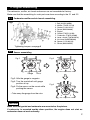
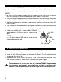
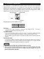
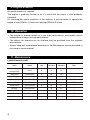
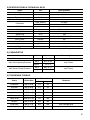
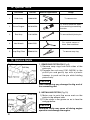
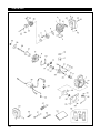
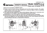
848-ES5-93A0 (704)
OWNER’S SERVICE MANUAL
MODEL:
G260PU-EI – for radio control Airplane
WARNING
• These engines are designed for radio
controlled products.
• When replacing parts, use only parts
which have been certified by Zenoah.
• Zenoah assumes that no responsibility for
these engines that are modified or used for
any other applications.
• Purchaser has all responsibility against
any laws and regulations existing in the
countries, Zenoah is exempt from such
laws and regulations.
• Read and completely understand this
OWNER'S SERVICE MANUAL before
operating these engines.
1. Safety Precautions
• This manual describes the engine. For its mounting and control, see the
instruction manual for the model airplane.
• Engine is designed for use on model airplane. If it is used for any other
purpose, we cannot be responsible for its reliability, safety and any
laws/regulations in the countries.
• Use genuine parts for replacement.
• Check the propeller, every time. If it is damaged, replace it with a new one.
• If the propeller hit something while the engine is in operation, immediately
stop the engine and check it.
• Start the engine on a flat surface without pebble stones.
• When mixing the fuel, or operating the engine, carry it out in a well-ventilated
place.
2
2. Engine Assembling
The carburetor, muffler, air-funnel and sensor are not assembled at factory.
Make sure that the assembling for such parts are done according to the 2.1 and 2.2.
2.1
Carburetor muffler and air-funnel assembling
Fig.1
1.
2.
3.
4.
5.
6.
7.
8.
9.
10.
11.
Bolt (01252-30550)
Muffler (T2075-15110)
Gasket (1140-13141)
Screw (0263-30408)
Engine
Gasket (T2075-13150)
Carburetor (T2075-81000)
Lever, choke (T2070-82410)
Air-funnel (848ES08300)
Spacer (1142-83110)
Screw (0263-30555)
Tightening torques: see page 9
2.2
Sensor assembling
Fig.3
Fig.2
Gauge
Rotor
Fig.2: Affix the gauge to magneto.
Fig.3: Turn the crankshaft until gauge
position at top.
Fig.4: Fix the sensor on the mount while
pushing the sensor.
Fig.4
• Take away the gauge from the rotor.
CAUTION
Make sure that gasket and carburetor are mounted as the picture.
If carburetor is mounted upside down position, the engine does not start as
carburetor does not work correctly.
3
3. Engine Mounting
Make sure that the G260PU-EI is mounted on the aircraft grade plywood with more
than 8mm of thickness or a mount of equivalent strength and is firmly fixed with 4 bolts.
If necessary, please reinforce the firewall and the around.
[ NOTE ]
1. Be sure to set flat washers or metal plate on the reverse side of the mount to prevent
bolts from sinking into the mount. Before be sure to check for loose bolts.
2. Since the engine is equipped with a float-less carburetor with a diaphragm pump, the
direction of cylinder and position of fuel tank can be freely selected .
3. The Fuel head between carburetor and bottom of fuel tank must be less than 100
mm (4 inches).
4. If the rubber joint is placed between the engine and the body for anti-vibration, check
if the rubber is too week and select the proper hardness of the rubber, in order to
avoid the unexpected vibration under operating engine RPM zone.
5. Tighten the nut (M8) with a torque of 80~120 kg·cm Fig.5
Nut (M8)
applying about 10~15 kg by hand as shown in the
figure.
(NOTE)
Do not tighten the nut (M8) with too large torque,
8cm
that may damage the stud.
10~15kg
(80~120kg·cm)
4. Ignition Unit Mounting
1. Make sure to install the power switch. (switch is not supplied)
2. Push the sparkplug cap all the way over the sparkplug. (use gloves)
3. Fixate the unit within the fuselage, as shown in the diagram. Do not wrap the unit by
the sponge, cloth or the like.
4. The temperature of the bottom surface (D) of the unit, in particular, will rise. Thus,
when fixating surface (D), make sure to leave sufficient space (a gap).
The temperature of the unit may rise to as high as 70~80°C, depending on
the operating environment and conditions, but this is not abnormal.
However, make sure not to touch this part or you could risk being burned.
4
Fig.6
Gap: 5mm or
more
surface D
surface D
surface D
surface D
Fig.7
Switch
Capacity: 3A (or higher)
(not supplied)
Sensor wire
Bolt (4mm)
Sponge & cloth
Unit
Battery wire
For charging
surface D
Ground wire
Sensor
Sparkplug wire
Use of anything
other than an 4.8V
battery is prohibited.
Battery 4.8V
1500~2700mA
(not supplied)
5. Propeller, Rotor & Screw Propeller
The recommended prop sizes are as shown in the table bellow.
Diameter x Pitch ( in.)
18 x 7 ~ 12, 16 x 10 ~ 14
Be sure to use a propeller which makes the engine speed approximately
7,500~8,500 rpm while the airplane is flying.
CAUTION
When mounting the spinner, set a pin on the hub with more than 3mm of
diameter, thus preventing slipping.
5
6. Fuel
• Mix gasoline (octane over 85 / premium gasoline) and high grade 2 cycle engine oil
(mixing use type; F3C grade or ISO EGC grade) at mixing ratio 25~40:1.
• The mixing ratio may be decided according to the oil recommendation.
[ NOTE ]
1) Never use any alcohol fuel or alcohol added fuel, or the rubber parts in the
carburetor. Will be damaged.
2) Gasoline is very flammable. Avoid smoking, bringing any fires near fuel.
3) To prevent all possible problems on fueling system, make sure to use the fuel filter
which has more than 300 mesh or equivalent and gasoline proof rubber pipe or
equivalent.
Incorrect fuel filter use causes engine trouble like carburetor's fuel passage stuffing
or piston surface scratching etc.
7. Starting
Make sure to fix a spinner and make sure that the helpers hold the airplane firmly. Also
make sure that the electric motor has a power enough to run the engine at minimum
1,100 rpm.
● How to start
a. Fill the fuel tank with the fuel.
b. Choke the carburetor.
c. Set the throttle valve at idle position or at the position slightly open from the idle
position (Never open the throttle more than 1/4 of full throttle stroke).
d. Turn the engine by electric motor until first combustion noise is heard.
e. Open the choke and keep the throttle valve at slight open position from idle position.
f. Turn the engine by electric motor, then the engine will start.
CAUTION
• Too much run by electric motor at choke condition may have a chance to wet
spark plug.
In this case, change the spark plug or dry it thoroughly and remove fuel rest in
the cylinder by turning engine under full throttle, open choke and without
spark plug installing.
• When engine is warm, carburetor choking may not be necessary.
• Hand flip starting is prohibited to prevent the hazards.
6
8. Carburetor Adjustment
The carburetor is provided with 3 adjust screws which are set to the best
(approximately) positions by our company, but they may need a little adjustment
depending on the temperature, atmospheric pressure (altitude), etc. of the area where
the engine is used. Start the engine without making any adjustments. Make
readjustments only when the engine shows any mal-running.
High Speed needle
Low Speed needle
Fig.8
Idle Screw
Standard opening of each needle as follows;
H
L
1 3/8 ± 1/4
1 3/8 ± 1/4
Idle Screw:
Turning this screw clockwise increases the idling R.P.M. Turning it
counterclockwise decreases the idling R.P.M
Low Speed needle:
This is the fuel adjust screw (not the air screw). Turning this needle clockwise
makes the mixture gas leaner and turning it counterclockwise makes it richer.
Set this needle at a position which is 1/4 open from best mixture (maximum R.P.M.)
position.
High Speed needle:
Turning this needle clockwise makes the mixture gas leaner and turning it
counterclockwise richer. Set this needle at a position which is 1/8~1/4 open from the
maximum R.P.M. position while the airplane is on ground.
CAUTION
1. Do not tighten the High and Low Speed needles too firmly.
2. When the unit has just started and the engine is not warm enough, there may
be insufficient acceleration and the engine may be stopped. Be sure to
perform idling before operation.
7
9. Engine Break-In
No specific break-in is required.
The engine is gradually broken-in as it is used and the output is also gradually
increased.
For checking the whole conditions of the airplane, it may be better to operate the
engine at slow RPM for 1/3 tank and mid-high RPM for 2/3 tank.
10. Operation
• The engine is already tuned up to get high performance, and needs correct
maintenance to keep such high performance.
• The details for operation as an airplane may be provided from the airplane
manufacturer.
• Always keep well maintenance according to the Maintenance clause described in
this owner's service manual.
11. Maintenance
1) MAINTENANCE CHART
8
Items
Action
Before
Use
Every
25 hours
Every
100 hours
Leakage,
Damage/Crack
Check
✔
✔
✔
✔
Note
Idling Speed
Check/Adjust
✔
✔
Spark Plug(gap)
Check/Adjust
✔
✔
Replace if necessary
Cylinder(barrel)
Check/Cleaning
✔
✔
↑
Piston, Ring
Check/Cleaning
✔
✔
↑
✔
✔
↑
✔
✔
↑
✔
Muffler & Bolt
Check/Cleaning
Bearings
Check/Cleaning
Crank Shaft
Check/Alignment
✔
↑
Rotor
Check
✔
✔
↑
Propeller Hub
Check/Alignment
✔
✔
↑
2) SPECIFICATIONS & TECHNICAL DATA
Items
Type
Bore x Stroke
Displacement
Effective Compression Ratio
unit
—
mm
cm3
Specifications
Air Cooled
34x28
25.4
8.4
Type (Walbro)
WT-645
Carburetor
Venturi (mm)
ø12.7
Air Cleaner
—
Starting
—
Electric Motor
Ignition
Type
Battery Ignition
Spark Plug
STD
Y82
Idle Speed
rpm
1800 (APC 18x8)
Max. Power
kW/rpm
NA
Max. Torque
N·m/rpm
NA
Fuel Consumption
g/kW·H
NA
Weight
kg
1.35 (✽)
(✽): Without Ignition System
Specifications are subject to change without notice.
3) CARBURETOR
Items
Unit
Standard
Measuring Device
Metering Lever set
mm
1.65 ± 0.16
Vanier
Inlet Valve Opening Pressure
Inlet Valve Closing Pressure
MPa
0.13~0.23
kg/cm2
1.3~2.3
MPa
0.07~0.17
kg/cm2
0.7~1.7
Leak Tester
Leak Tester
4) TIGHTENING TORQUE
Standard
Items
Screw Size
Carburetor
M5 (P=0.8)
Insulator
M5 (P=0.8)
4.4
45
Rotor
M8 (P=1.0)
12.7
130
N·m
kg·cm
3.4
35
Cylinder
M5 (P=0.8)
6.9
70
Crankcase
M5 (P=0.8)
5.9
60
Spark Plug
M10 (P=1.0)
7.8
80
Muffler
M5 (P=0.8)
8.8
90
Stud (hub)
M6 (P=1.0)
9.8
100
Nut, Propeller
M8 (P=1.25)
9.8
100
Remarks
with Locktight glue
9
12. Special Tools
Part Name
Part No.
External Appearance
Usage
1
Puller Assy
1490-96101
To remove rotor.
2
Piston Stopper
4810-96220
To hold crankshaft when
disassembling/assembling
the rotor.
3
Rod Assy
1101-96220
To remove/install piston pin.
4
Hex Wrench
3304-97611
For socket screw of
4mm, 5mm and 6mm.
5
Snap Ring Pliers
5500-96110
To remove snap ring.
13. Service Guide
Fig.9
1. REMOVING PISTON PIN (Fig.9)
1) Remove snap rings from both sides of the
piston pin.
2) Engage the rod assy(1101-96220) to the
piston pin and gently tap with a plastic
hammer to push out the pin while holding
piston firmly.
CAUTION
Hard hammering may damage the big end of
the connecting rod.
2. INSTALLING PISTON (Fig.10)
1) Make sure to point the arrow mark on the
piston to the exhaust side.
2) Fit the circlip in the groove so as to face the
end gap below.
Fig.10
CAUTION
Deformed circlip may come off during engine
operation and damage the engine.
10
14. Warranty
1) SCOPE OF APPLICATION
This engine manufactured by Zenoah Co., Ltd. (hereinafter referred as ZENOAH) and
sold to the user directly or through distributor/manufacturer, shall entitle to be covered
by this warranty.
2) LIMIT OF WARRANTY
ZENOAH warrants that ;
1. The quality disclosed in the specifications.
2. The engine which shall be considered defective by ZENOAH, caused by material
or production fault.
3) LIMITS OF COMPENSATION
1. ZENOAH compensates such quality, material and production faults by repairing or
replacing through distributor/manufacturer.
2. ZENOAH shall not compensate any other accompanied or benefit losses caused
to user and distributor/manufacturer by such faults and through repairing or
replacing.
4) TERMS OF WARRANTY
3 months after purchased by user subject to 12 months from produced month.
5) EXEMPT FROM WARRANTY
ZENOAH shall not warrant this engine even if the fault has been caused during the
period of terms of warranty, in case of that ;
1. Any faults, failures caused from neglect of this OWNER'S SERVICE MANUAL for
proper operation and maintenance.
2. Any modifications not approved by ZENOAH.
3. Normal abrasion and deterioration.
4. Consuming parts.
5. Using any parts which have not been certified by ZENOAH.
6. Add-on or modified parts use.
11
Parts list
24
Parts list
Key#
1
2
3
4
5
6
Part Number
Description
7
8
9
10
11
12
13
14
15
16
17
18
19
20
21
22
23
24
25
26
27
28
29
30
31
32
33
34
35
36
37
38
39
40
41
42
43
44
45
46
47
848ES512A0
T2075-13120
3310-12281
T2075-13150
1148-13162
T2075-14120
T2075-21100
–
–
2629-21130
T2075-21140
2169-21210
1155-21240
04065-02812
06034-06001
1850-21220
01252-30530
T2088-41110
T2088-41210
1600-41310
1260-41320
5500-41410
1101-41340
T2075-42000
848ES553X0
0262-10516
1650-43230
848ES57110
1000-43240
1140-43250
848EW07120
3699-92369
0263-30555
1142-83110
848ES08300
T2070-82410
T2075-81000
1152-43260
1152-43281
1152-43290
3350-53410
1140-13141
01252-30550
0263-30408
T2075-15110
8488441400
848EW071N0
1490-96101
CYLINDER
GASKET, cylinder
BOLT M5x20
GASKET, insulator
INSULATOR
GASKET, carburetor
CRANKCASE COMP.
• CRANKCASE (R)
• CRANKCASE (F)
• PIN
GASKET
SEAL 12x22x7
BEARING
SNAPRING
BEARING
SEAL 12x28x7
BOLT M5x30
PISTON
RING
PISTON PIN
SNAP RING
BEARING
WASHER
CRANKHAFT COMP.
MOUNT
SCREW M5x16
NUT M8
ROTOR COMP.
KEY
SHIM
UNIT ASSY
SPARK PLUG
SCREW M5x55
SPACER 5x10x1.6
AIR-funnel
LEVER CHOKE
CARBURETOR ASSY
HUB
STUD
WASHER
NUT M8
GASKET, muffler
BOLT M5x50
SCREW M4x8
MUFFLER
BOLT SENSOR
SENSOR
PULLER ASSY
49
50
51
52
53
54
55
848ES596C0
4810-96220
1101-96220
8488U30000
1148-08010
848ES593A0
X374320099
GAUGE
STOPPER
ROD ASSY
SPANNER
MUFFLER
MANUAL
REPAIR KIT (PLUG CAP)
Q'TY/
UNIT
1
1
6
1
1
1
1
1
1
3
1
1
2
1
1
1
4
1
1
1
2
1
2
1
1
3
1
1
1
0~3
1
1
2
2
1
1
1
1
1
1
1
1
2
2
1
2
1
1
1
1
1
1
1
1
1
Remarks
Y82
WT-645
OPTION
OPTION
OPTION
OPTION
OPTION KIT
25
Parts list
CARBURETOR INNER PARTS
26
Key#
Part Number
1
2
3
4
5
6
7
8
T2075-81000
3306-81380
3080-81120
3310-81130
3304-81140
1172-81150
2850-81290
3310-81260
10
3310-81280
12
13
14
15
16
17
18
19
20
21
22
23
24
25
26
27
28
29
30
31
32
33
34
35
36
2867-81270
3356-81310
1480-81420
3310-81230
3310-81240
3310-81250
2630-81330
3350-81380
1172-81370
2670-81410
2880-81470
3310-81340
1148-81390
T2070-81460
T2075-81450
3350-81350
3350-81220
3310-81351
1491-81160
1148-81171
3080-81320
T2070-81330
3304-81450
3304-81441
3360-81440
Description
Q'TY/
UNIT
CARBURETOR ASSY
• SCREEN
• COVER
• SCREW
• GASKET
• DIAPHRAGM
• GASKET
• DIAPHRAGM
1
1
1
1
1
1
1
1
METERING COVER
1
• SPRING
• VALVE, inlet
• PLUG, welch
• LEVER
• SCREW
• PIN
• SCREW
• SPRING
• SHAFT, throttle
• SPRING
• SCREW
• VALVE, throttle
• RING
• SHAFT, choke
• VALVE, choke
• SPRING
• BALL
• SCREW
• SPRING
• NEEDLE, low speed
• SPRING
• NEEDLE, high speed
• SCREEN
• RING
• PLUG
1
1
1
1
1
1
1
1
1
1
2
1
1
1
1
1
1
4
1
1
1
1
1
1
1
Head Office : 1-9 Minamidai, Kawagoe-city, Saitama, 350-1165 Japan
Phone: (+81)49-243-1115 Fax: (+81)49-243-7197
本社:〒350-1165 埼玉県川越市南台 1-9
サービスG: (049)243-1110