1
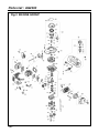
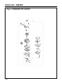
3898-93110 (711) OWNER / OPERATOR MANUAL POWER AUGER AG2300 (NOTE: Drill is optional part.) WARNING The engine exhaust from this product contains chemicals known to the State of California to cause cancer, birth defects or other reproductive harm. Thank you for purchasing a RedMax product. Before using our power auger, please read this manual carefully to understand the proper use of your unit. Read this manual carefully to understand all safety precautions, controls, proper operation and maintenance of your RedMax power auger. Failure to do so could result in serious injury. SAFETY FIRST Instructions contained in warnings within this manual marked with a symbol concern critical points which must be taken into consideration to prevent possible serious bodily injury, and for this reason you are requested to read all such instructions carefully and follow them without fail. Note that there may be times when warning seals peel off or become soiled and impossible to read. If this happens, you should contact the dealer from which you purchased the product to order new seals and affix the new seal(s) in the required location(s). ■ Notes on types of warnings WARNING IMPORTANT NOTE Instructions labeled as shown at left, concern critical steps or procedures which must be followed in order to prevent accidents which could lead to serious bodily injury or death. This mark is used to indicate instructions which must be followed without exception. Instructions labeled as shown at left concern steps or procedures which, if not followed correctly, could lead to mechanical failure, breakdown, or damage. Used to label supplementary instructions designed to provide hints or directions useful in the use of the product. CONTENTS SAFETY PRECAUTIONS .................................................................................. 4 IN ORDER TO ENSURE PROPER AND SAFE OPERATION OF YOUR POWER AUGER WORK GEAR AND CLOTHING WARNINGS CONSIDERING HANDLING OF FUEL THINGS TO CHECK BEFORE USING YOUR POWER AUGER THINGS TO CHECK BEFORE STARTING UP THE ENGINE AVOID NOISE PROBLEM THINGS TO BE CAREFUL ABOUT WHEN USING YOUR POWER AUGER NOTES ON CARE AND MAINTENANCE OF YOUR POWER AUGER FUEL .................................................................................................................. 9 HOW TO MIX FUEL FUELING THE UNIT OPERATION ..................................................................................................... 10 INSTALLING DRILL THROTTLE CABLE ADJUSTMENT STARTING ENGINE STOPPING ENGINE DRILLING ADJUSTMENT OF IDLING SPEED MAINTENANCE ............................................................................................... 12 DAILY INSPECTION INSPECTION EVERY 25 HOURS INSPECTION EVERY 100 HOURS STORAGE ........................................................................................................ 13 BEFORE LONG-TERM STORAGE SPECIFICATIONS ............................................................................................ 14 PARTS LIST ..................................................................................................... 15 Safety Precautions ■ In order to ensure proper and safe operation of your power auger • Avoid running the engine indoors. The exhaust gases contain harmful carbon monoxide. • Read this Owner/Operator Manual carefully. Be sure you understand how to operate this unit properly before you use it. Failure to do so could result in serious injury. • Be sure to keep this manual handy so that you may refer to it later whenever any questions arise. Also note that you are requested to contact the dealer from whom you purchased the product for assistance in the event that you have any questions which cannot be answered herein. • Always be sure to include this manual when selling, lending, or otherwise transferring the ownership of this product. • This product has been designed for use in earth drilling, and it should never be used for any other purpose since doing so could result in unforeseen accidents and injuries occurring. • You should never use this power auger when under the influence of alcohol, when suffering from exhaustion or lack of sleep, when suffering from drowsiness as a result of having taken cold medicine, or at any other time when a possibility exists that your judgment might be impaired or that you might not be able to operate the power auger properly and in a safe manner. Also be sure never to allow children or anyone unable to fully understand the directions given in this manual to use this power auger. 4 • Never use your power auger under circumstances like those described below: 1. When the ground is slippery or when other conditions exist which might make it not possible to maintain a steady posture while using the power auger. 2. At night, at times of heavy fog, or at any other times when your field of vision might be limited and it would be difficult to gain a clear view of the area where the power auger is to be used to ensure safety. 3. During rain storms, during lightning storms, at times of strong or gale-force winds, or at any other times when weather conditions might make it unsafe to use this product. • When using this product for the first time, before beginning actual work, take the power auger to a wide, clear, open space, turn on the power, and practice handling the power auger until you are sure that you will be able to handle in it properly in actual operation. • Lack of sleep, tiredness, or physical exhaustion results in lower attention spans, and this in turn leads to accidents and injury. When planning your work schedule, allow plenty of time to perform the work of cutting and allow plenty of time for rest. Limit the amount of time over which the power auger is to be used continuously to somewhere around 30~40 minutes per session, and take 10~20 minutes of rest between work sessions. Also try to keep the total amount of work performed in a single day under 2 hours or less. Safety Precautions ■ Work gear and clothing ■ Warnings considering handling of fuel • When using your power auger, always be sure to wear strong, durable, work clothing; shirts should be long-sleeved shirts and pants should be full-length pants reaching down to the ankles. • The engine of the power auger is designed to run on a mixed fuel which contains highly flammable gasoline. This fuel is highly flammable and you should never store cans of fuel or refill the tank of the power auger in any place where there is a boiler, stove, wood fire, electrical sparks, welding sparks, or any other source of heat or fire which might ignite the fuel. • Always be sure to wear and helmet and face protector when using your power auger. • When using your power auger, always be sure to wear thick work gloves to protect your hands and non-slip-sole work boots to prevent you from slipping. Never use your power auger when wearing pants with loose cuffs, when wearing sandals, or when barefoot. • When using your power auger for an extended period of time, you should wear ear protectors to protect yourself from loss of hearing from overexposure to high levels of sound. • Smoking while operating the power auger or refilling its fuel tank is extremely dangerous. Always be sure to keep lit cigarettes away from the power auger at all times. • When refilling the tank always turn off the engine first and take a careful look around to make sure that there are no sparks or open flames anywhere nearby before refueling. • If any fuel spillage occurs during refueling, always be sure to use a dry rag to wipe any fuel which has been spilled onto the power auger before turning the engine back on again. • After refueling, screw the fuel cap back tightly onto the fuel tank and then carry the power auger to a spot 10 feet or more away from where it was refueled before turning on the engine. 5 Safety Precautions ■ Things to check before using your power auger ■ Things to check before starting up the engine • Before beginning work, look around carefully to get a feel for the shape of the land, and whether or not there are any obstacles which might get in the way while working, and remove any obstacles which can be cleared away before beginning work. • Take a careful look around to make sure that no obstacles exist within a perimeter of 15 feet or less around the power auger before starting the engine. • The area within a perimeter of 45 feet of the person using the power auger should be considered a hazardous area into which no one should enter while the power auger is in use, and when necessary yellow warning rope, warning signs, or some other form of warnings should be placed around the perimeter of the area. When work is to be performed simultaneously by two or more persons, care should also be taken to constantly look around or otherwise check for the presence and locations of other people using power auger within the work area so as to maintain a distance between each person sufficient to ensure safety. • Before beginning work, each component of the power auger should be checked to make sure that it is in proper working order and to make sure that there are no loose screws or bolts, fuel leaks, ruptures, dents, or any other problems which might interfere with safe operation. Be especially careful at this time to check that there is nothing wrong with the drills or with the joints by which the drills are attached to the power auger. • The power auger is equipped with a centrifugal clutch mechanism which causes the drills to begin to rotate as soon as the engine is started by putting the throttle into the start position. When starting the engine, hold it firmly in place so as to ensure that nor the throttle may not come into contact with any obstacles when the engine starts up. • Never place the throttle into the high speed position when starting the engine. • After starting up the engine, check to make sure that the drills stop rotating when the throttle is moved fully back to its original position. If the drills continue to rotate even after the throttle has been moved fully back, turn off the engine and take the unit to your authorized Red Max servicing dealer for repair. ■ AVOID NOISE PROBLEM NOTE Check and follow the local regulations as to sound level and hours of operations for power auger. • In general, operate power auger between 8a.m.and 5p.m.on week days and 9a.m.to 5p.m.weekends. Avoid using power auger late at night and/or early in the morning. 6 Safety Precautions ■ Things to be careful about when using your power auger • When using your power auger, grip the handles of the power auger firmly with both hands, place your feet slightly apart (slightly further apart than the width of your shoulders) so that your weight is distributed evenly across both legs, and always be sure to maintain a steady, even posture while working. • Maintain the speed of the engine at the level required to perform drilling work, and never raise the speed of the engine above the level necessary. • Always be sure never to allow other persons to come within the work area while drilling. • Be especially careful not to slip if it is raining or if rain has just stopped, as the ground is likely to be slippery at such times. • If the grass or other object gets caught in the blade during operation, always be sure to turn off the engine before removing the object. • Guard against hazardous situations at all times. Warn adults to keep pets and children away from the area. Establish a safe method for gaining your attention during operation. Be careful if you are approached. • If someone calls out or otherwise interrupts you while working, always be sure to turn off the engine before turning around. • Keep operation area clear of all persons, particularly small children and pets. • Never touch the spark plug or plug cord while the engine is in operation. Doing so may result in being subjected to an electrical shock. • Never touch the muffler, spark plug, or other metallic parts of the engine while the engine is in operation or immediately after shutting down the engine. These metallic parts reach high temperatures during operation and doing so could result in serious burns. • When you finish drilling in one location and wish to continue work in another spot, turn off the engine before carrying it to the new location. • Never transport the power auger over rough roads over long distances without first removing all fuel from the fuel tank, as doing so might cause fuel to leak from the tank as a result of shocks absorbed during transport. 7 Safety Precautions ■ Notes on care and maintenance of your power auger • In order to maintain your power auger in proper working order, perform the maintenance and checking operations described in this manual at regular intervals. In the event that any parts must be replaced or any maintenance or repair work not described in this manual must be performed, please contact a representative from the store nearest RedMax authorized servicing dealer for assistance. • Under no circumstances should you ever take apart the power auger or alter it in any way. Doing so might result in the power auger becoming damaged during operation or the power auger becoming unable to operate properly. • Always be sure to turn off the engine before performing any maintenance or checking procedures. • When removing, or reattaching the drills, be sure to wear thick, sturdy gloves and use only proper tools and equipment to prevent injury. • When replacing drills or any other parts or when replacing the oil or any lubricants, always be sure to use only RedMax products or products which have been certified by RedMax for use with the power auger. • Do not use any accessory or attachment other than those bearing the RedMax mark and recommended for the unit. 8 Fuel WARNING • Gasoline is very flammable. Avoid smoking or bringing any flame or sparks near fuel. Make sure to stop the engine and allow it cool before refueling the unit. Select outdoor bare ground for fueling and move at least 3m(10ft) away from the fueling stop before starting the engine. • The RedMax engines are lubricated by oil specially formulated for air-cooled 2-cycle gasoline engine use. If RedMax oil is not available. Use an anti-oxidant added quality oil expressly labeled for air-cooled 2-cycle engine use. RECOMMENDED MIXING RATIO GASOLINE 32:OIL 1 • Poor quality gasolines or oils may damage sealing rings, fuel lines or fuel tank of the engine. ■ HOW TO MIX FUEL 1. Measure out the quantities of gasoline and oil to be mixed. 2. Put some of the gasoline into a clean, approved fuel container. 3. Pour in all of the oil and agitate well. 4. Pour in the rest of gasoline and agitate again for at least one minute. 5. Put a clear indication on the outside of the container to avoid mixing up with gasoline or other containers. 6. Indicate the contents on outside of container for easy identification. ■ FUELING THE UNIT 1. Untwist and remove the fuel cap. Rest the cap on a dustless place. 2. Put fuel into the fuel tank to 80% of the full capacity. 3. Fasten the fuel cap securely and wipe up any fuel spillage around the unit. WARNING • Exhaust emission are controlled by the fundamental engine parameters and components(eq., carburation, ignition timing and port timing) without addition of any major hardware or the introduction of an inert material during combustion. 32:1 MIXING CHART GASOLINE gal. 1 2 3 4 5 2-CYCLE OIL fl.oz 4 8 12 16 20 • These engines are certified to operate on unleaded gasoline. • Make sure to use gasoline with a minimum octane number of 90 ROZ (USA/Canada : pump octane min.87) • Unleaded gasoline is recommended to reduce the contamination of the air for the sake of your health and the environment. 1. Select bare ground for fueling. 2. Move at least 10 feet (3 meters) away from the fueling point before starting the engine. 3. Stop the engine before refueling the unit. FOR YOUR ENGINE LIFE, AVOID; 1. FUEL WITH NO OIL(RAW GASOLINE) – It will cause severre damage to the internal engine parts very quickly. 2. GASOHOL – It can cause deterioration of rubber and/or plastic parts and disruption of engine lubrication. 3. OIL FOR 4-CYCLE ENGINE USE or WATER COOLED 2-CYCLE ENGINE USE – It can cause spark plug fouling, exhaust port blocking, or piston ring sticking. 4.Mixed fuels which have been left unused for a period of one month or more may clog the carburetor or result in the engine failing to operate properly. 9 Operation ■ Installing Drill 1. Slide the ring clip and remove the lock pin from the drill. 2. Put the drill onto the auger output shaft and insert the lock pin. Cover it with the ring clip. ■ Throttle Cable Adjustment Check the throttle cable play and adjust to .04 or .08 in. at the carburetor side. ■ Starting Engine 1. When first starting up after putting fuel into the machine, or when re-starting after running out of fuel, push the priming pump until fuel runs out the overflow pipe. 2. Close the choke (push the choke lever front ward). 3. While pulling the throttle lever, push in the throttle lock and set the throttle lever to the starting position. NOTE • The throttle lock makes starting easier. Always use it when starting the engine. 5. While firmly holding the auger as illustrated, vigorously pull the starter rope. 6. When engine has ignited first, open the choke (move the choke lever backward), pull the starter rope again and the engine will start. WARNING • Keep the drill clear of everything around it as they will start moving with the engine start. 7. Pull the throttle lever slightly, and it will be unlocked automatically. 8. Allow the engine to warm up for a couple of minutes before starting operation. NOTE • When re-starting immediately after stopping engine, keep the choke open. • If the engine won't start even after repeated attempts, it may be overfed with fuel. Remove and dry the spark plug, and try to start again with the choke open. 10 Operation ■ Stopping Engine • Release the throttle lever and press on the red button until the engine comes to a complete stop. • When the drill has been caught in the ground and cannot be pulled out, lock up the drill and rotate the auger to draw it back. 1. First stop the engine. 2. Put the lock pin into the holes provided on the gear case and output shaft. 3. Rotate the auger counter-clockwise as viewed from the operator. ■ Drilling • Keep a firm grip of the auger at all times on a wide stance and by holding the handle with both hands. • A reacting motion may occur on the auger when spinning drill has hit on stones or tree roots under the ground. Always hold the auger securely to control such motion. • Start drilling with half-throttle, and gradually increase the engine speed so that the drill may get into the ground smoothly. ■ Adjustment of Idling Speed • The engine idling speed is preadjusted at the factory so that the engine keeps running without moving the drill when releasing the throttle lever to the idling position. However, due to changes in engine conditions, it may be necessary to adjust the idling. • To increase idling, screw idle adjustment screw in, until preferred speed is obtained. To decrease idling, unscrew idle adjustment screw until preferred speed is obtained. 11 Maintenance WARNING • Before cleaning, inspecting or repairing your unit, make sure that engine has stopped and is cool. Disconnect the spark plug terminal to avoid accidental engine starts. ■ Daily Inspection • Remove grass or dust, from the entire body. • Check that all nuts and screws are securely tightened, and no parts are missing. • Check for leakage of fuel. • Check and clean the spark plug. Adjust the electrode gap to .024~.028 if necessary. Replacement plug: Champion RCJ6Y ■ Inspection every 100 hours • The muffler is equipped with a spark arrester to prevent red hot carbon from flying out of the exhaust outlet. In the State of California it is required by law (Section 4442 of the California Public Resources Code) to equip a spark arrester when a gas powered tool is used in any forest covered, brush covered, or grass covered unimproved land. ■ Inspection every 25 hours • Remove the air cleaner element from the carburetor air intake cover and wash in warm, soapy water. Dry completely before installing. • Check and tighten each fastener. • Dismount the engine and check the clutch system to see if oil is observed between the clutch lining and its drum. If any, wipe it off with gasoline. 12 Storage ■ Before Long-term Storage • Drain fuel tank and run engine out until all fuel in the carburetor is used up. • Remove the spark plug and drop a spoonful 2 cycle oil into the cylinder. Crank the engine several times and replace the plug. Pull starter until compression is felt. • Brush off dirt from the drill surface and apply rust protective oil. • Store the machine in a dry, dust-free place. 13 Specifications Model Name AG2300 Engine Displacement cu.in(cc) ........................................................................................1.37 (22.5) Maximum power HP ....................................................................................1.2 at 7500 rpm Carburetor ............................................................................................Diaphragm (Walbro) ignition system ...........................................................................................Electronic (T.C.I) Spark plug ...............................................................................................Champion RCJ6Y Starter .............................................................................................................Recoil starter Fuel .............................................................................2 cycle oil premixed gasoline (32:1 ) Fuel tank capacity fl.oz(lit) ...............................................................................................20 (0.6) Transmission ..................................................................Centrifugal clutch, spur gear reduction Gear box lubricant ..................................................................................................Grease (L#0) Reduction ratio .....................................................................................................................35:1 Grip span in (mm) ..........................................................................................................20 (505) Over all dimensions Length in (mm) .....................................................................................................24.8 (630) Width in (mm) .........................................................................................................9.8 (250) Height w/o drill in (mm) ........................................................................................13.4 (340) Dry weight w/o drill Ids (kg) ..........................................................................................10.6 (4.8) Adaptable drill size Diameter in (mm) ..................................................................................0.8 to 2.4 (20 to 60) Specifications are subject to change without notice. 14 Parts List POWER AUGER AG2300 NOTE : 1. Use KOMATSU ZENOAH genuine parts as specified in the parts list for repair and/or replacement. 2. KOMATSU ZENOAH does not warrant the machines, which have been damaged by the use of any parts other than those specified by the company. 3. When placing parts orders for repair and/or replacement, check if the model name and the serial number are applicable to those specified in the parts list, then use parts number described in the parts list. 4. The contents described in the parts list are accurate as of July 1997 and may change due to improvement. 5. The parts for the machine shall be supplied seven (7) years after the machine is discontinued. [It is possible that some specific parts may be subject to change of their delivery term and list price within the limit of ten (7) years after the machine is discontinued. It is also possible that some parts may be available even after the limit of seven (7) years.] 15 Parts List : AG2300 Fig.1 AUGER DRIVE SHAFT GROUP 16 AG2300 Fig.1 AUGER DRIVE SHAFT GROUP Key# Part Number 1 2 3 4 5 6 7 8 9 10 11 12 13 14 15 16 17 18 19 20 21 22 23 24 25 26 27 28 3890-11101 3890-11112 3890-11140 3890-11201 06030-06001 06031-06001 06030-06202 06034-06202 3127-13230 04065-03515 3890-12110 04064-01210 3890-13100 3890-13110 3890-13121 3890-13131 3890-13140 04010-00310 3890-13210 0224-00610 01641-20608 3310-12281 0225-10616 3890-14100 3890-14110 3541-14221 0225-30616 3524-14400 Description CASE(A)COMP • CASE(A) • PIN CASE(B)COMP BEARING BEARING BEARING BEARING SPACER RING DRUM RING GEAR COMP • GEAR • SHAFT GEAR SHAFT KEY SHAFT BOLT WASHER BOLT BOLT HANDLE COMP • HANDLE • GRIP • BOLT LEVER Q'ty Key# Part Number Description Q'ty 1 1 2 1 1 1 1 1 1 1 1 1 1 1 1 1 1 1 1 1 1 4 4 1 1 2 4 1 17 Parts List : AG2300 Fig.2 DRILL and ACCESSORY GROUP 18 AG2300 Fig.2 DRILL and ACCESSORY GROUP Key# Part Number 1 2 3 4 5 6 7 8 9 10 11 12 13 14 15 16 17 18 19 20 21 22 23 24 25 26 27 28 29 30 31 32 33 34 35 36 37 38 39 40 41 42 43 44 45 3206-52700 3206-52710 3200-51130 3200-51140 3206-52800 3206-52810 3200-51130 3200-51140 3202-51102 3202-51112 3202-51121 3200-51130 3200-51140 3206-52100 3206-52110 3202-52121 01225-40620 0280-10605 0290-20615 3206-52330 3200-51130 3200-51140 3206-52200 3206-52210 3206-52220 01225-40620 0280-10605 0290-20615 3206-52330 3200-51130 3200-51140 3204-53100 3204-53110 3200-51130 3200-51140 3204-53200 3204-53210 3200-51130 3200-51140 3890-91000 1030-91340 1110-91320 3540-91120 3540-93120 3890-91511 Description DRILL S20 ASSY • DRILL S20 • PIN • CLIP DRILL S30 ASSY • DRILL S30 • PIN • CLIP DRILL S40 ASSY • DRILL S40 • BIT • PIN • CLIP DRILL S60 ASSY • DRILL S60 • TIP S60 • SCREW • NUT • WASHER • BIT • PIN • CLIP DRILL S90 ASSY • DRILL S90 • TIP S90 • SCREW • NUT • WASHER • BIT • PIN • CLIP JOINT-L100 ASSY • JOINT-L100 • PIN • CLIP JOINT-L300 ASSY • JOINT-L300 • PIN • CLIP TOOL SET • DRIVER • SOCKET • SPANNER BAND PIN Q'ty Key# Part Number Description Q'ty 1 1 1 1 1 1 1 1 1 1 1 1 1 1 1 1 2 2 2 1 1 1 1 1 1 2 2 2 1 1 1 1 1 1 1 1 1 1 1 1 1 1 1 1 1 19 Parts List : AG2300 Fig.3 ENGINE GROUP 20 AG2300 Fig.3 ENGINE GROUP Key# Part Number 1 2 3 4 5 6 7 8 9 10 11 12 13 14 15 16 17 18 19 20 21 22 23 24 25 26 27 28 29 30 31 32 33 34 35 36 37 38 39 40 41 42 43 44 45 46 47 48 49 50 51 52 5602-12110 5500-12211 1850-12130 5500-13162 5500-13120 5500-13130 0263-90520 5602-15110 1601-15120 01252-30550 5500-15210 5600-15220 0263-90416 5600-21100 5500-21140 06030-06001 2169-21210 1850-21220 04065-02812 01252-30530 5600-41111 1100-41210 1101-41310 1260-41320 1140-41330 1101-41340 5600-42001 1650-43230 1000-43240 1140-51111 1140-51250 1970-51221 1140-51230 1970-51241 1140-21161 0263-90516 5600-52150 1650-43230 5601-71110 5501-71201 5500-71220 2616-71320 1900-72111 1900-72120 5500-72130 1260-71261 3310-72150 1861-75100 1861-75110 1861-75120 1861-75130 1861-75141 Description CYLINDER GASKET,base BOLT INSULATOR GASKET,insulator GASKET,carburetor SCREW M5x20 MUFFLER • ARRESTER BOLT M5x50 GASKET,muffler PLATE,muffler SCREW M4x16 CRANKCASE COMP GASKET,case BEARING 12x28x8 OIL SEAL 12x22x7 OIL SEAL 12x28x7 SNAP RING ø28 BOLT M5x30 PISTON ø32 RING ø32 PIN ø8 SNAP RING BEARING 8x11x9 THRUST WASHER CRANKSHAFT COMP NUT M8 KEY SHOE,clutch SCREW,clutch SPRING,clutch WASHER,flat WASHER,wave CASE,clutch SCREW M5x16 PLATE NUT M8 ROTOR COIL ASSY • CORD • CAP,cord CAP PLUG SPRING GROMMET SPACER BOLT M4x25 RECOIL ASSY • CASE • SPIRING,spairal • REEL • RATCHET Q'ty Key# 1 1 2 1 1 1 2 1 1 2 1 1 1 1 1 2 1 1 1 4 1 2 1 2 1 2 1 1 1 2 2 1 2 2 1 4 1 1 1 1 1 1 1 1 1 2 2 1 1 1 1 1 53 54 55 56 57 58 59 60 61 62 63 64 65 66 67 68 69 70 71 72 73 74 75 76 77 78 79 80 81 82 83 84 85 86 87 88 89 Part Number 1861-75150 1483-75270 1487-75160 1487-75170 1861-75180 1490-75180 0263-90412 0263-90560 1950-86120 5500-82102 1970-82190 5500-82131 5500-82140 2630-33610 5500-82171 5600-82201 5500-82221 5500-82230 5600-31110 0263-90520 5600-32100 1850-32160 1900-31410 5602-73110 5606-73200 1753-82100 5600-85002 5600-85202 5600-85231 5600-85240 5600-85250 5500-85220 5500-85300 5500-85400 1260-85460 5500-85510 5617-91120 Description • WASHER • SCREW • RETAINER • WASHER • ROPE • KNOB SCREW M4x12 SCREW M5x60 CLIP BODY ASSY • SLEEVE • PLATE,choke • LEVER,choke • SCREW ø4 CR ELEMENT,filter COVER ASSY • KNOB • RING COVER,fan SCREW M5x20 COVER,engine ASSY SCREW M4x12 SCREW ø4 CR SPARKPLUG RCJ-6Y SWITCH ASSY CABLE COMP TANK ASSY • CAP ASSY • • HOLDER • • CAP • • VALVE • • PACKING • PIPE COMP • FILTER ASSY • CLIP SCREW M5x16 LABEL,recoil Q'ty 1 1 1 1 1 1 4 2 1 1 2 1 1 1 1 1 1 1 1 4 1 1 1 1 1 1 1 1 1 1 1 1 1 1 1 3 1 21 Parts List : AG2300 Fig.4 CARBURETOR GROUP 22 AG2300 Fig.4 CARBURETOR GROUP Key# 1 2 3 4 5 6 7 8 9 10 11 12 13 14 15 16 17 18 19 20 21 22 23 24 25 26 27 Part Number 5501-81000 1752-81110 5500-81120 1751-81130 1881-81140 5501-81150 1918-81170 1751-81180 1881-81130 1751-81240 5500-81251 3310-81260 1065-81410 1065-81420 1850-81450 3306-81380 3356-81310 1850-81270 1850-81220 3310-81250 3310-81230 1850-81470 1850-81490 1751-81510 1850-81520 1850-81530 5500-81160 Description Q'ty CARBURETOR ASSY WYJ-113 • SCREW • BRACKET • E-RING • SWIVEL • VALVE ASSY • SCREW,adjust • NUT • RING • O-RING • JET • DIAPHRAGM • GASKET,pump • DIAPHRAGM,pump • BODY ASSY • • SCREEN • • VALVE,inlet • • SPRING • • SCREW • • PIN • • LEVER • GASKET • BODY,air purge • PUMP,priming • COVER,pump • SCREW • WASHER 1 2 1 1 1 1 1 1 1 1 1 1 1 1 1 1 1 1 1 1 1 1 1 1 1 4 1 Key# Part Number Description Q'ty 23 RedMax® POWER AUGER MODEL AG2300 2-YEAR LIMITED WARRANTY For two (2) years [1 year if used commercially] from the date of original purchase of the model AG2300 unit, KOMATSU ZENOAH AMERICA INC. (the “Company”), through any RedMax® dealer, will repair or replace, free of charge, for the original purchaser, any part found to be defective in material and/or workmanship. This is the exclusive remedy. The purchaser shall bear costs of transporting the model AG2300 to and from the RedMax® dealers. This warranty does not apply to those units which have been damaged by accident, mishandling, alteration, abuse, improper lubrication, the use of any parts or accessories other than those specified by the Company, or other causes beyond our control. This warranty does not cover those parts replaced for normal wear or harmless changes in their appearance. There are no other express warranties. IMPLIED WARRANTIES including those of merchantability and fitness for a particular purpose ARE LIMITED to one (1) year from the original purchase date. Liabilities for incidental or consequential damages under any and all warranties are excluded. Some states do not allow limitations on how long an implied warranty lasts or the exclusion or limitation of incidental or consequential damages, so the above limitation or exclusion may not apply to you. This warranty gives you specific legal rights, and you may also have other rights which vary from state to state. If you need to obtain information about the nearest service center, please call KOMATSU ZENOAH AMERICA INC. at (770)-381-5147. IMPORTANT: You will receive a Warranty Registration Card at time of purchase. Please fill out the card and send it to RedMax / KOMATSU ZENOAH AMERICA within seven (7) days. Be sure to keep a copy for your records. KOMATSU ZENOAH AMERICA INC. 1505 Pavilion Place Suite A Norcross, Georgia 30093 © Printed in Japan