1
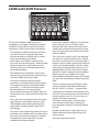
Front of House Mixing Consoles 4 BUS MIXING CONSOLE WITH USB I/O & DUAL 24BIT DIGITAL EFFECTS Safety Instructions/Consignes de sécurité/Sicherheitsvorkehrungen WARNING: To reduce the risk of fire or electric shock, do not expose this unit to rain or moisture. To reduce the hazard of electrical shock, do not remove cover or back. No user serviceable parts inside. Please refer all servicing to qualified personnel.The lightning flash with an arrowhead symbol within an equilateral triangle, is intended to alert the user to the presence of uninsulated "dangerous voltage" within the products enclosure that may be of sufficient magnitude to constitute a risk of electric shock to persons. The exclamation point within an equilateral triangle is intended to alert the user to the presence of important operating and maintenance (servicing) instructions in the literature accompanying the product. Important Safety Instructions 1. Please read all instructions before operating the unit. 2. Keep these instructions for future reference. 3. Please heed all safety warnings. 4. Follow manufacturers instructions. 5. Do not use this unit near water or moisture. 6. Clean only with a damp cloth. 7.Do not block any of the ventilation openings. Install in accordance with the manufacturers instructions. 8. Do not install near any heat sources such as radiators, heat registers, stoves, or other apparatus (including amplifiers) that produce heat. 9. Do not defeat the safety purpose of the polarized or grounding-type plug. A polarized plug has two blades with one wider than the other. A grounding type plug has two blades and a third grounding prong. The wide blade or third prong is provided for your safety. When the provided plug does not fit your outlet, consult an electrician for replacement of the obsolete outlet. 10. Protect the power cord from being walked on and pinched particularly at plugs, convenience receptacles and at the point at which they exit from the unit. 11. Unplug this unit during lightning storms or when unused for long periods of time. 12.Refer all servicing to qualified personnel. Servicing is required when the unit has been damaged in any way, such as power supply cord or plug damage, or if liquid has been spilled or objects have fallen into the unit, the unit has been exposed to rain or moisture, does not operate normally, or has been dropped. ATTENTION: Pour éviter tout risque d’électrocution ou d’incendie, ne pas exposer cet appareil à la pluie ou à l’humidité. Pour éviter tout risque d’électrocution, ne pas ôter le couvercle ou le dos du boîtier. Cet appareil ne contient aucune pièce remplaçable par l'utilisateur. Confiez toutes les réparations à un personnel qualifié. Le signe avec un éclair dans un triangle prévient l’utilisateur de la présence d’une tension dangereuse et non isolée dans l’appareil. Cette tension constitue un risque d’électrocution. Le signe avec un point d’exclamation dans un triangle prévient l’utilisateur d’instructions importantes relatives à l’utilisation et à la maintenance du produit. Consignes de sécurité importantes 1. Veuillez lire toutes les instructions avant d’utiliser l’appareil. 2. Conserver ces instructions pour toute lecture ultérieure. 3. Lisez avec attention toutes les consignes de sécurité. 4. Suivez les instructions du fabricant. 5.Ne pas utiliser cet appareil près d’une source liquide ou dans un lieu humide. 6. Nettoyez l’appareil uniquement avec un tissu humide. 7.Veillez à ne pas obstruer les fentes prévues pour la ventilation de l’appareil. Installez l’appareil selon les instructions du fabricant. 8. Ne pas installer près d’une source de chaleur (radiateurs, etc.) ou de tout équipement susceptible de générer de la chaleur (amplificateurs de puissance par exemple). 9. Ne pas retirer la terre du cordon secteur ou de la prise murale. Les fiches canadiennes avec polarisation (avec une lame plus large) ne doivent pas être modifiées. Si votre prise murale ne correspond pas au modèle fourni, consultez votre électricien. 10. Protégez le cordon secteur contre tous les dommages possibles (pincement, tension, torsion,, etc.). Veillez à ce que le cordon secteur soit libre, en particulier à sa sortie du boîtier. 11. Déconnectez l’appareil du secteur en présence d’orage ou lors de périodes d’inutilisation prolongées. 12.Consultez un service de réparation qualifié pour tout dysfonctionnement (dommage sur le cordon secteur, baisse de performances, exposition à la pluie, projection liquide dans l’appareil, introduction d’un objet dans le boîtier, etc.). ACHTUNG: Um die Gefahr eines Brandes oder Stromschlags zu verringern, sollten Sie dieses Gerät weder Regen noch Feuchtigkeit aussetzen.Um die Gefahr eines Stromschlags zu verringern, sollten Sie weder Deckel noch Rückwand des Geräts entfernen. Im Innern befinden sich keine Teile, die vom Anwender gewartet werden können. Überlassen Sie die Wartung qualifiziertem Fachpersonal.Der Blitz mit Pfeilspitze im gleichseitigen Dreieck soll den Anwender vor nichtisolierter “gefährlicher Spannung” im Geräteinnern warnen. Diese Spannung kann so hoch sein, dass die Gefahr eines Stromschlags besteht. Das Ausrufezeichen im gleichseitigen Dreieck soll den Anwender auf wichtige Bedienungs- und Wartungsanleitungen aufmerksam machen, die im mitgelieferten Informationsmaterial näher beschrieben werden. Wichtige Sicherheitsvorkehrungen 1. Lesen Sie alle Anleitungen, bevor Sie das Gerät in Betrieb nehmen. 2. Bewahren Sie diese Anleitungen für den späteren Gebrauch gut auf. 3. Bitte treffen Sie alle beschriebenen Sicherheitsvorkehrungen. 4. Befolgen Sie die Anleitungen des Herstellers. 5. Benutzen Sie das Gerät nicht in der Nähe von Wasser oder Feuchtigkeit. 6. Verwenden Sie zur Reinigung des Geräts nur ein feuchtes Tuch. 7.Blockieren Sie keine Belüftungsöffnungen. Nehmen Sie den Einbau des Geräts nur entsprechend den Anweisungen des Herstellers vor. 8. Bauen Sie das Gerät nicht in der Nähe von Wärmequellen wie Heizkörpern, Wärmeklappen, Öfen oder anderen Geräten (inklusive Verstärkern) ein, die Hitze erzeugen. 9. Setzen Sie die Sicherheitsfunktion des polarisierten oder geerdeten Steckers nicht außer Kraft. Ein polarisierter Stecker hat zwei flache, unterschiedlich breite Pole. Ein geerdeter Stecker hat zwei flache Pole und einen dritten Erdungsstift. Der breitere Pol oder der dritte Stift dient Ihrer Sicherheit. Wenn der vorhandene Stecker nicht in Ihre Steckdose passt, lassen Sie die veraltete Steckdose von einem Elektriker ersetzen. 10. Schützen Sie das Netzkabel dahingehend, dass niemand darüber laufen und es nicht geknickt werden kann. Achten Sie hierbei besonders auf Netzstecker, Mehrfachsteckdosen und den Kabelanschluss am Gerät. 11. Ziehen Sie den Netzstecker des Geräts bei Gewittern oder längeren Betriebspausen aus der Steckdose. 12.Überlassen Sie die Wartung qualifiziertem Fachpersonal. Eine Wartung ist notwendig, wenn das Gerät auf irgendeine Weise, beispielsweise am Kabel oder Netzstecker beschädigt wurde, oder wenn Flüssigkeiten oder Objekte in das Gerät gelangt sind, es Regen oder Feuchtigkeit ausgesetzt war, nicht mehr wie gewohnt betrieben werden kann oder fallen gelassen wurde. Instrucciones de seguridad / Istruzioni di Sicurezza PRECAUCION: Para reducir el riesgo de incendios o descargas, no permita que este aparato quede expuesto a la lluvia o la humedad. Para reducir el riesgo de descarga eléctrica, nunca quite la tapa ni el chasis. Dentro del aparato no hay piezas susceptibles de ser reparadas por el usuario. Dirija cualquier reparación al servicio técnico oficial. El símbolo del relámpago dentro del triángulo equilátero pretende advertir al usuario de la presencia de “voltajes peligrosos” no aislados dentro de la carcasa del producto, que pueden ser de la magnitud suficiente como para constituir un riesgo de descarga eléctrica a las personas. El símbolo de exclamación dentro del triángulo equilátero quiere advertirle de la existencia de importantes instrucciones de manejo y mantenimiento (reparaciones) en los documentos que se adjuntan con este aparato. Instrucciones importantes de seguridad 1. Lea todo este manual de instrucciones antes de comenzar a usar la unidad. 2. Conserve estas instrucciones para cualquier consulta en el futuro. 3. Cumpla con todo lo indicado en las precauciones de seguridad. 4. Observe y siga todas las instrucciones del fabricante. 5. Nunca utilice este aparato cerca del agua o en lugares húmedos. 6. Limpie este aparato solo con un trapo suave y ligeramente humedecido. 7.No bloquee ninguna de las aberturas de ventilación. Instale este aparato de acuerdo a las instrucciones del fabricante. 8. No instale este aparato cerca de fuentes de calor como radiadores, calentadores, hornos u otros aparatos (incluyendo amplificadores) que produzcan calor. 9. No anule el sistema de seguridad del enchufe de tipo polarizado o con toma de tierra. Un enchufe polarizado tiene dos bornes, uno más ancho que el otro. Uno con toma de tierra tiene dos bornes normales y un tercero para la conexión a tierra. El borne ancho o el tercero se incluyen como medida de seguridad. Cuando el enchufe no encaje en su salida de corriente, llame a un electricista para que le cambie su salida anticuada. 10. Evite que el cable de corriente quede en una posición en la que pueda ser pisado o aplastado, especialmente en los enchufes, receptáculos y en el punto en el que salen de la unidad. 11. Desconecte de la corriente este aparato durante las tormentas eléctricas o cuando no lo vaya a usar durante un periodo de tiempo largo. 12. Dirija cualquier posible reparación solo al servicio técnico oficial. Deberá hacer que su aparato sea reparado cuando esté dañado de alguna forma, como si el cable de corriente o el enchufe están dañados, o si se han derramado líquidos o se ha introducido algún objeto dentro de la unidad, si esta ha quedado expuesta a la lluvia o la humedad, si no funciona normalmente o si ha caído al suelo. ATTENZIONE: per ridurre il rischio di incendio o di scariche elettriche, non esponete questo apparecchio a pioggia o umidità. Per ridurre il pericolo di scariche elettriche evitate di rimuoverne il coperchio o il pannello posteriore. Non esistono all'interno dell'apparecchio parti la cui regolazione è a cura dell'utente. Per eventuale assistenza, fate riferimento esclusivamente a personale qualificato. Il fulmine con la punta a freccia all'interno di un triangolo equilatero avvisa l'utente della presenza di "tensioni pericolose" non isolate all'interno dell'apparecchio, tali da costituire un possibile rischio di scariche elettriche dannose per le persone. Il punto esclamativo all'interno di un triangolo equilatero avvisa l'utente della presenza di importanti istruzioni di manutenzione (assistenza) nella documentazione che accompagna il prodotto. Importanti Istruzioni di Sicurezza 1. Prima di usare l'apparecchio, vi preghiamo di leggerne per intero le istruzioni. 2. Conservate tali istruzioni per una eventuale consultazione futura. 3. Vi preghiamo di rispettare tutte le istruzioni di sicurezza. 4. Seguite tutte le istruzioni del costruttore. 5. Non usate questo apparecchio vicino ad acqua o umidità. 6. Pulite l'apparecchio esclusivamente con un panno asciutto. 7.Evitate di ostruire una qualsiasi delle aperture di ventilazione. Posizionatelo seguendo le istruzioni del costruttore. 8. Non posizionatelo vicino a sorgenti di calore come radiatori, scambiatori di calore, forni o altri apparecchi (amplificatori compresi) in grado di generare calore. 9. Non disattivate la protezione di sicurezza costituita dalla spina polarizzata o dotata di collegamento a terra. Una spina polarizzata è dotata di due spinotti, uno più piccolo ed uno più grande. Una spina dotata di collegamento a terra è dotata di due spinotti più un terzo spinotto di collegamento a terra. Questo terzo spinotto, eventualmente anche più grande, viene fornito per la vostra sicurezza. Se la spina fornita in dotazione non si adatta alla vostra presa, consultate un elettricista per la sostituzione della presa obsoleta. 10. Proteggete il cavo di alimentazione in modo che non sia possibile camminarci sopra né piegarlo, con particolare attenzione alle prese, ai punti di collegamento e al punto in cui esce dall'apparecchio. 11. Staccate l'apparecchio dalla alimentazione in caso di temporali o tempeste o se non lo usate per un lungo periodo. 12.Per l'assistenza, fate riferimento esclusivamente a personale qualificato. È necessaria l'assistenza se l'apparecchio ha subito un qualsiasi tipo di danno, come danni al cavo o alla spina di alimentazione, nel caso in cui sia stato versato del liquido o siano caduti oggetti al suo interno, sia stato esposto a pioggia o umidità, non funzioni correttamente o sia stato fatto cadere. Copyright 2008 - Samson Technologies Corp. Printed March, 2008 v1.2 Samson Technologies Corp. 45 Gilpin Avenue Hauppauge, New York 11788-8816 Phone: 1-800-3-SAMSON (1-800-372-6766) Fax: 631-784-2201 www.samsontech.com Table of Contents Introduction . . . . . . . . . . . . . . . . . . . . . . . . . . . . . . . . . . . . . . . . . . . 1 L2400 And L3200 Features . . . . . . . . . . . . . . . . . . . . . . . . . . . . . . . . . 2 Controls And Functions . . . . . . . . . . . . . . . . . . . . . . . . . . . . . . . . 3 - 11 Input Channel Section . . . . . . . . . . . . . . . . . . . . . . . . . . . . . . . . . . . 3 24 Bit Digital Effect Section . . . . . . . . . . . . . . . . . . . . . . . . . . . . . . . . 6 Master Auxiliary Send Section . . . . . . . . . . . . . . . . . . . . . . . . . . . . . . 7 Stereo Aux Return Input . . . . . . . . . . . . . . . . . . . . . . . . . . . . . . . . . 8 Meter Section . . . . . . . . . . . . . . . . . . . . . . . . . . . . . . . . . . . . . . . . 9 Talkback Section . . . . . . . . . . . . . . . . . . . . . . . . . . . . . . . . . . . . . 10 Group Output Section . . . . . . . . . . . . . . . . . . . . . . . . . . . . . . . . . . 10 Mono/subwoofer Output Section . . . . . . . . . . . . . . . . . . . . . . . . 10 - 11 Main Output Section . . . . . . . . . . . . . . . . . . . . . . . . . . . . . . . . . . . 11 L2400 And L3200 Input and Output Connections . . . . . . . . . . . . . . 12 - 13 Using The USB I/O . . . . . . . . . . . . . . . . . . . . . . . . . . . . . . . . . . . . . . 15 Getting Started With Windows XP . . . . . . . . . . . . . . . . . . . . . . . . . . 15 Getting Started With Mac OS X . . . . . . . . . . . . . . . . . . . . . . . . . . . . 16 Recording From The L Series’ USB I/O . . . . . . . . . . . . . . . . . . . . . . . . 17 Playing Back From The L Series’ USB I/O . . . . . . . . . . . . . . . . . . . . . . . 17 L2400 And L3200 Wiring Guide . . . . . . . . . . . . . . . . . . . . . . . . . . . . . 18 Specifications . . . . . . . . . . . . . . . . . . . . . . . . . . . . . . . . . . . . . . 19 - 20 Block Diagram . . . . . . . . . . . . . . . . . . . . . . . . . . . . . . . . . . . . . . . . 21 Introduction Congratulations on your purchase of the Samson L2400 or L3200 mixing console! The L2400 and L3200 are twenty-four and thirty-two channel, true 4 bus consoles, with USB input and outputs in ergonomically correct, attractively appointed enclosures. The L Series include professional features such as high quality mic pre amplifiers, 3-band, swept mid EQ, 100 mm faders and 6 auxiliary busses, with up to eight mixes possible. Connecting all your microphones and instruments is simple, with 16 mic/line inputs plus four additional stereo channels on the L2400, and 24mic/line inputs plus four additional stereo channels on the L3200. In addition, each console has two extra mic preamplifiers on the stereo channels, bringing the total number of mic inputs to 18 on the L2400 and 26 on the L3200. There are also dedicated stereo effects returns for the onboard digital effects. And the effects! You can add one of 100 dazzling digital studio quality effects, which include Delays, Chorus, Flanging, and of course, lush Reverbs to your vocals or instruments using the onboard 24-bit multieffects processor. It’s easy to dial up your favorite effects preset with the large seven-segment LED display. Need more effects? The L Series’ employs two onboard 24-bit multi-effects processors. Plus, the L Series mixers have extensive auxiliary busses, allowing you to have complex combinations of effects on all the channels, or two different effects on different groups of channels. The auxiliary buses are also extremely flexible when it comes to monitor mixes and up to six simultaneous monitor mixes are possible. The L series consoles also feature a sophisticated onboard USB digital interface allowing you to record and playback digital audio from virtually any PC running most any recording software. The flexible routing option lets you assign the USB output to send the signal from the Main stereo mix, or use the aux sends to record a completely independent mix. The L2400 and L3200 will give you clean, clear sound reproduction thanks to the advanced circuit topology, high quality components, low noise microphone preamps and super clean, low impedance mix bus design. The super-tough steel construction ensures reliable, high quality sound from venue-to-venue and performance-to-performance day in, and night out. Perfectly suited for recording, live sound reinforcement and commercial installations, the L2400 and L3200 mixers are ideal solutions that offer plenty of inputs, sweet sounding effects and studio quality sound in a convenient package. In these pages, you’ll find a detailed description of the features of the L Series consoles, as well as a guided tour through its control panel, stepby-step instructions for its setup and use, and full specifications. You’ll also find a warranty card enclosed—please don’t forget to fill it out and mail it in so that you can receive online technical support and so we can send you updated information about these and other Samson products in the future. Also, be sure to check out our website (www. samsontech.com) for complete information about our full product line. With proper care and adequate air circulation, your L-Series mixer will operate trouble free for many years. We recommend you record your serial number in the space provided below for future reference. Serial number: _________________________ Date of purchase: _______________________ Should your unit ever require servicing, a Return Authorization number (RA) must be obtained before shipping your unit to Samson. Without this number, the unit will not be accepted. Please call Samson at 1-800-3SAMSON (1-800-372-6766) for a Return Authorization number prior to shipping your unit. Please retain the original packing materials and if possible, return the unit in the original carton and packing materials. If you purchased your Samson product outside the United States, please contact your local distributor for warranty information and service. L2400 and L3200 Features The Samson L2400 and L3200 consoles are comprehensive and great sounding making them suitable for a variety of live sound and recording applications. Here are some of their main features: •Each of the L2400 and L3200’s mic / line channels feature Gain control, Low Cut filter, a threeband equalizer with variable mid-range control enabling you to tailor the tonal response of each input, and a convenient Insert Point jack to patch in external effects. •The L2400 and L3200 are twenty four and thirty two channel mixers in ergonomically correct, table-top enclosures providing easy to see and easy to operate front panel controls. •The L Series has 6 auxiliary sends. Two dedicated pre -fader Aux sends for monitors, plus a second pair of Aux sends that can be set up to be either a monitor send or an effects send using the Pre/Post switch, and two additional EFX sends for sending to the dual internal multi-effects processors. For added flexibility, the EFX sends can be routed to the AUX 5-6 output instead of the internal effects allowing you to set up 8 different aux mixes. •Ample inputs, the L2400 has sixteen mic/line inputs plus four stereo line inputs, while the L3200 features twenty four mic/line inputs plus four stereo line inputs. Plus dedicated stereo returns for the onboard effects. • Two additional mic preamplifiers on the stereo channels brings the total number of mic inputs to 18 on the L2400 and 26 on the L3200. •Dedicated Mono/Subwoofer Output with variable Low-pass Filter controlled by a 100mm long throw fader. •On board, bi-directional USB interface for recording to a computer based Hard disk system. The Output routing can be selectedfrom MAIN mix or AUX 1 - 2, and the Input routing can be from the MAIN mix or last stereo channel. •Two pairs of twelve segment LED Meters which can be switched to display Main left and right with AFL and PFL, or Groups 1 - 4 output levels. •A comprehensive Talkback section including XLR mic input with phantom power, Level control and routing switches to Aux 1/2, Aux 3/4, Group 1/2, Group 3/4 and Main mix outputs. •Custom designed, long throw (100mm) faders on all channels, busses, mono and left and right main outputs. •The L series have two onboard 24-bit DSP (Digital Signal Processor) multi-effects processors with 100 selectable presets offering dazzling studio quality effects including Reverb, Delay, Chorus and Flanging. •The brilliant sound quality is achieved thanks to the advanced circuit design, utilizing lownoise operational amplifiers and low impedance bussing. •Durable steel enclosure is road tough insuring reliable performance from night to night and venue to venue. •The L Series mixers feature high-quality, low-noise microphone pre-amplifiers that can accept signals from most any standard microphone. Condenser microphones are connected easily using the available 48 Volt Phantom Power. • Three-year extended warranty. Controls and Functions Mono Inputs Stereo Inputs 1 SIGNAL -30 -10 GAIN 1 The following section details each part of the L2400 and L3200’s INPUT CHANNELS including the 3-BAND EQ, the MONITOR and EFX sends, PAN, GAIN and VOLUME controls. SIGNAL -30 0 GAIN 2 -10 +20 -20 3 LOW CUT 75Hz 18dB/OCT AUX 1 AUX 2 AUX 4 4 AUX 2 5 AUX 4 EFX 1 7 EFX 2 8 AUX 5 AUX 6 HF 800 Auxiliary Buses ( 4 - 8 ) The L Series include several auxiliary signal paths, or buses, that can be used to create independent mixes for sending to the internal or external effects processors, or to an external monitor system. These buses start by sending the signal from each individual channel, which is set with one of the auxiliary control knobs. Then, the mix of all the channels auxiliary level is ultimately sent to either an internal effects processor, or to an output jack to connect to an external effect or monitor system. To help you control your effects and monitor mixes, the L series has six auxiliary buses, with switching to give you a possibility of 8 mixes. AUX 5 AUX 6 HF 12K MF 3 - LOW CUT Switch Each of the L Series’ channels include a LOW CUT (or high pass) filter which rolls off the low frequencies from 75Hz and below at the rate of 18dB per octave. PRE / POST EFX 1 EFX 2 2 - GAIN Control Knob The L2400 and L3200’s pre-amp stage has a variable GAIN control with a range of -6 to -50dB on the MIC input and +14 to -30dB on the LINE input. AUX 3 6 PRE / POST 1 – SIGNAL LED The L2400 and L3200’s MIC/LINE pre-amp also includes a SIGNAL LED which, when illuminated, indicates that a signal is present at the input. AUX 1 AUX 3 12K HI-MID 9 3K FREQ LO-MID Hz 100 INPUT CHANNEL SECTION 25/26 500 8k LF LF 80 80 PAN BALANCE 10 CH 1 11 PEAK 10 PFL 5 1-2 0 3-4 5 MAIN 12 CH 17/18 PEAK 10 13 14 15 16 PFL 5 1-2 0 3-4 5 MAIN 10 10 15 15 20 20 30 30 40 PRE….? POST….? What’s That? In order to operate your mixer correctly, it is important to understand the concept of PRE and POST fader sends. An auxiliary bus that is set up as PRE Fader routes, or sends, the signal to its output from a point in the channels’ circuit that is electronically before the channel Fader. That means the channel Fader has no effect on the PRE aux level. A Pre Fader send is what you want to use for a monitor mix, so when the level is changed for the mix in the main PA speakers using the channel Fader, the level in the monitor set by the aux control knob remains the same. An auxiliary bus that is set up as POST Fader routes, or sends, the signal to its output from a point in the channels’ circuit that is electronically after the channel Fader. 40 17 CH 1 1 to 24 on the L3200 1 to 16 on the L2400 CH 17/18 25/26 to 31/32 on the L3200 17/18 to 23/24 on the L3200 Controls and Functions INPUT CHANNEL SECTION - continued That means that the channel Fader also affects the level of a POST aux send. A POST Auxiliary bus is what you want to use (almost always) for sending to an effects processor, either internal or external. When using the POST aux sends, (while turning the channel Fader up or down) the level of effects will track the channel level correctly. independently on each channel. The channel’s EFX12 knob controls the amount of signal that is sent to each the two EFX bus feeding the two internal DSP effect processors. For additional flexibility, the EFX12 signal can also be sent to an external effect device connected to the AUX 5-6 Output jacks located on 5 the rear panel jack field. 8 – AUX 5-6 - switch The AUX 5-6 switch is used to select the point that the EFX1-2 / AUX 5-6 uses to send the signal. When a channel’s AUX 5-6 switch is set6to on (down), the signal from that channel is routed to the AUX 5-6 bus. This separate mix can be sent to an external effect device connected to the AUX 5-6 jacks located on the rear panel jack field. 4 – AUX 1-2 Pre Fader Send Each of the L series’ input channels include a pair of Pre Fader Auxiliary sends; AUX 1-2 and their control knobs adjust the amount of that channel’s signal that is sent to the AUX 1-2 Output. The signal feeding AUX 1-2 is sent before, or pre, the channel Fader, so the channel Fader has no effect on the AUX 1-2 output levels. The AUX 1-2 busses are usually used to create a separate mix for a floor monitor system. 7 9 - Channel Equalizer - Mono Channels The L2400 and L3200 mic/line input channels incorporate a 3-band, swept-mid equalizer allowing you to adjust the high, mid-range, and low frequencies independently on each channel. The frequency centers, range of boost or cut, and equalizer type for each band are described in the following section: 5 – AUX 3-4 – Pre/Post Fader Each of the L series’ input channels include a pair Auxiliary sends which can switch from Pre to Post sends; AUX 3-4 and their control knobs adjust the amount of that channel’s signal that is sent to the AUX 3-4 Output. Aux 3-4 can be configured for pre or post fader send using the PRE/POST switch (6). The AUX 3-4 bus is usually used to create a separate mix for a floor monitor system, but you can set the Pre/Post switch to Post to use the send as en effects bus to an external processor. HF (HIGH FREQUENCY) 12kHz +/- 15dB Shelving type The channel’s HIGH frequency response is flat when the knob is in the “12:00” position. Rotating the knob towards the right will boost the channel's high frequency response at 12 kHz by 15dB, and rotating it towards the left will cut the high frequency by 15dB. 6- PRE/POST - switch The PRE/POST switch is used to select the point that the AUX 3-4 bus uses to send the signal. When the PRE/POST switch is set to PRE, the signal feeding AUX 3-4 is sent before the fader, so the channel Fader has no effect on that level. This is the normal setting when using AUX 3-4 as a monitor send. When the PRE/POST switch is set to POST, the signal feeding AUX 3-4 is sent after the fader, so the channel Fader has an effect on that level, meaning the Aux level tracks up and down with the channel Fader. This is the normal setting for using AUX 3-4 as an effects send, since when you set the channel loude,r you normally want the effect to get louder. MF (MID FREQUENCY) CUT & BOOST The MF knob is used in conjunction with the FREQ knob to create the tonal shape in the midrange frequency when using the mono channel’s equalizers. You can adjust the frequency on the mid-range control with the FREQ knob, and use the MF control to either boost or cut that frequency by plus or minus 15dB. The channel’s MID frequency response is flat when the MF knob is in the “12:00” position. FREQ (MID FREQUENCY) Variable 100Hz – 8K The FREQ is a control enabling you enhanced capabilities in the tonal shaping of the input channel signal. Thanks to the FREQ control, you have a variable mid-range equalizer, allowing you to pin point the exact frequency you want to boost or cut. The MID SWEEP has a “fixed Q” of two octaves (the amount, or width, of frequencies Channel Fader up or down the level of effects will track the channel level correctly. 7 – EFX1-2 / AUX 5-6 - Post Fader Send The L series provide high quality, 24 Bit digital effects, and the level of effects can be set Controls and Functions 12 – PEAK LED The L2400 and L3200’s MIC/LINE pre-amp also includes a PEAK LED which when illuminated, indicates that the signal is peaking or overloading. To reduce distortion, lower the GAIN control to keep this LED from staying on. INPUT CHANNEL SECTION - continued around the center point that are effected by the MID CUT & BOOST control) and can be set in a range from 100Hz to 8Khz. LF (LOW FREQUENCY) 80Hz +/- 15dB shelving type The channel’s LOW frequency response is flat when the knob is in the “12:00” position. Rotating the knob towards the right will boost the channel's low frequency response at 80 Hertz by 15dB, and rotating it towards the left will cut the frequency by 15dB. 13 - PFL (Pre Fader Listen) switch The Mono Input channel’s PFL, or Pre Fader Listen switch allows you to listen, or “solo” a channel or group of channels in the headphones. When the PFL switch is pressed down, the channel is assigned to the solo bus and can be heard in headphones plugged in to the PHONES connector located in the front panel jack field. Since the signal is sent pre fader, you can hear the signal regardless of the position of the channel volume Fader. This allows you to listen to a channel by itself: (let's say) to see if an artist is out of tune, or to cue up a channel without having to play it through the main PA speakers. 9 - Channel Equalizer - Stereo Channels The L2400 and L3200 Stereo input channels feature a 4-band equalizer allowing you to adjust the high, mid, and low frequencies independently on each channel. The stereo channel equalizer is laid out like a mono input on the control panel input strip, but internally, the equalizer is affecting a stereo signal path. The channel’s frequency response is flat when the knobs are in the “12:00” position. Rotating the knob towards the right will boost the corresponding frequency band by 15dB, and rotating it towards the left will cut the frequency by 15dB. The frequency centers, range of boost or cut, and equalizer type for each band are as follows: 14 - 1-2 Group Assign switch The 1-2 Group assign switch is used to assign the input channel to the 1-2 Group output bus. Note: The Group output follows the channel’s PAN control, so if a channel is panned all the way to the left it will only feed Group Output 1. Conversely, if a channel is panned all the way to the right, it will only feed Group Output 2. High: 12kHz +/- 15dB shelving type High Mid: 3kHz +/- 15dB peaking type Lo Mid: 500 kHz +/- 15dB peaking type 15 – 3-4 Group Assign switch The 3-4 Group assign switch is used to assign the input channel to the 3-4 Group output bus. Low: 80Hz +/- 15dB shelving type 10 - PAN Control The L2400 and L3200’s PAN control is used to place or position the mono signal into the stereo main Left and Right MIX bus. You can create a stereo image by panning some input signals to the left and others to the right. The L2400 and L3200’s PAN control is a Power-Pan circuit, which includes a 3dB dip in the center position. This is desirable since there’s a 3dB increase in gain when the mono input signal is heard in both the Left and Right MIX bus. Note: The Group output follows the channel’s PAN control so if a channel is panned all the way to the left, it will only feed Group Output 3. Conversely, if a channel is panned all the way to the right, it will only feed Group Output 4. 16 –MAIN Assign switch The MAIN assign switch is used to assign the input channel to the left and right stereo bus outputs. 17- VOLUME - Fader Level Control The VOLUME Fader control adjusts the level of each mono input channel. 11 - MUTE switch The Mono Input channels feature a large, backlit MUTE switch allowing you to easily turn that channel on or off. When MUTE switch is illuminated, the channel is off. Conversely, when the backlight is off, the channel is on. Controls and Functions 24BIT DIGITAL EFFECT SECTION 24 BIT DIGITAL EFFECT SECTION The L2400 and L3200 feature built-in, 24 Bit Digital Multieffects Processor(s) with 100 dazzling, studio quality effects like Delay, Chorus, Flanging and lush Reverbs including Halls, Plates and Rooms. In addition, there are multi-effects presets that have two effects combined together. For example, Delay and Reverb or Reverb and Chorus, to name a few. The following section describes the features control knobs and layout of the powerful onboard digital Multi-effects section. EFFECTS 18 19 PROGRAM 1 PROGRAM 2 00-09 00-09 PERFORMANCE PERFORMANCE 10-19 10-19 HALL REVERB HALL REVERB 20-29 20-29 PLATE REVERB PLATE REVERB 30-39 30-39 SPRING REVERB SPRING REVERB 40-49 40-49 ECHO ECHO 50-59 50-59 FLANGE+VERB FLANGE+VERB 60-69 60-69 CHORUS+VERB CHORUS+VERB 70-79 70-79 ECHO+VERB ECHO+VERB 80-89 80-89 CHORUS CHORUS 90-99 90-99 FLANGE FLANGE 18 - Program Effects Display The L Series mixers Multi-effects Processors feature a dual digit, seven-segment numerical Effects Display for showing the effects PROGRAM number from 00 - 99. You will see the PROGRAM numbers change as you scroll through the effects pre-set using the DSP SELECT control. When the Effects Display shows two straight lines through the center of each segment, the effects are turned off and the EFX ON switch is in the out position. See section number 25 below. 20 19 - Effect PROGRAM List 21 22 TO AUX 1 TO AUX 1 TO AUX 2 TO AUX 2 TO AUX 3 TO AUX 3 TO AUX 4 TO AUX 4 This section identifies the ten banks of built-in DSP effects presets. The first bank of 10 presets have been programmed with common effects for live performance, and the following banks are set up in groups by the types of effects. 20- SELECT control knob 23 24 25 26 EFX 1 28 29 30 PEAK 31 PEAK 10 PFL 5 22 – TO AUX 2 - Effects Return Control The TO AUX 2 control is used to adjust the level of the effects from the built-in digital Multi-effect being that’s being sent to the AUX 2 monitor bus. This allows you to add the DSP effects to the signal in your monitor speakers. Turn this knob up if you want to hear the effect in the AUX 3 monitor mix. PFL 5 1-2 0 1-2 32 0 3-4 5 21 - TO AUX 1 - Effects Return to Aux 1 control knob The TO AUX 1 control is used to adjust the level of the effects from the built-in digital Multi-effect that’s being sent to the AUX 1 monitor bus. This allows you to add the DSP effects to the signal in your monitor speakers. Turn this knob up if you want to hear the effect in the AUX 1 monitor mix. EFX 2 10 27 The SELECT control knob is a continuously variable encoder, or tweaker, that allows you to call up one of the 100 built-in digital effects presets. Simply rotate the SELECT knob to scroll through the preset programs using the Effects Display to choose the effect number you want. MAIN 3-4 5 10 10 15 15 20 20 30 30 40 40 RTN 1 MAIN 23 – TO AUX 3- Effects Return Control The TO AUX 3 control is used to adjust the level of the effects from the built-in digital Multi-effect being that’s being sent to the AUX 2 monitor bus. This allows you to add the DSP effects to the signal in your monitor speakers. Turn this knob up if you want to hear the effect in the AUX 3 monitor mix. RTN 2 Controls and Functions 32 – Effect 2 control strip 24BIT DIGITAL EFFECT SECTION - continued Same as functions 18 – 31 for DSP Multi-effects number 2. 24 – TO AUX 4- Effects Return Control The TO AUX 4 control is used to adjust the level of the effects from the built-in digital Multi-effect that’s being sent to the AUX 4 monitor bus. This allows you to add the DSP effects to the signal in your monitor speakers. Turn this knob up if you want to hear the effect in the AUX 4 monitor mix. Master Auxiliary Send Section AUX SEND AUX 1 AFL 25 – EFX ON switch AUX 2 The EFX ON switch is used to turn the internal Digital Effect on and off. The effects are by-passed when the switch is in the out position and the Effects Display shows two dashes. AFL AUX 3 AFL 26– PEAK - LED The L2400 and L3200’s DSP section also includes a PEAK LED which when illuminated, indicates that the signal is peaking or overloading. To reduce distortion, lower the EFX controls to keep this LED from staying on. AUX 4 AFL 33 34 AUX 5 AFL 27 - PFL EFX RTN 1 (Pre Fader Listen) - switch AUX 6 The EFX RTN 1’s PFL, or Pre Fader Listen switch allows you to listen, or “solo” the EFX 1 Return or group of channels in the headphones. When a stereo input channel’s PFL switch is pressed down, the EFX RTN 1 signal is assigned to the solo bus and can be heard in headphones plugged in to the PHONES connector located in the front panel jack field. Since the signal is sent pre fader, you can hear the signal regardless of the position of the EXF RTN 1 volume Fader. This allows you to listen a EFX RTN 1 by itself: (let's say) to see if a reverb is long enough, or to cue up an echo without having to play it through the main PA. AFL EFX 1 AFL EFX 2 AFL 33 - AUX 1 - 8 Master Send Fader Each of the L Series AUX 1-8 buses has a master control knob, which is used to adjust the overall level of that AUX bus output. The Aux 1-8 signals from mono and stereo input channels, along with the DSP returns are mixed together and sent to the AUX 1-8 Output respectively. Use the AUX 1-8 level controls to set the amount of signal being sent to Aux 1-8 Output. 28 - 1-2 RTN1 Group Assign switch The 1-2 Group assign switch is used to assign the DSP RTN1 to the 1-2 Group output bus. 29 – 3-4 RTN 1 Group Assign switch The 3-4 assign switch is used to assign the DSP RTN 1 to the 3-4 Group output bus. 30 –MAIN Assign switch The MAIN assign switch is used to assign the DSP RTN 1to the left and right stereo bus outputs. 34 - AUX 1 - 8 AFL switch The AUX 1-8 master send output’s AFL, or After Fader Listen switch allows you to listen, or “solo” an AUX send in the headphones. When any the AUX 1-8 AFL switch is pressed down, that Aux’s signal is assigned to the solo bus and can be heard in headphones plugged in to the PHONES connector located in the front panel jack field. This allows you to listen to an AUX send by itself, let’s say, to check that a signal is not distorted before it gets to the power amplifier. Since the signal is sent after the Aux 1 level fader, you hear the signal with the added gain from the AUX 1 Level control. 31- RTN1 - Fader Level Control The RTN1 Fader control adjusts the level of the DSP 1 effects in the MAIN left and right mix. Controls and Functions RETURN feeds AUX1 / AUX2. When the SHIFT switch is in the down position, the STEREO AUX RETURN feeds AUX3 / AUX4. STEREO AUX RETURN Input STEREO AUX RETURN 1 39 - PFL switch The STEREO AUX RETURN’s PFL, or Pre Fader Listen switch, allows you to listen to, or “solo”, the STEREO AUX RETURN in the headphones. When the stereo input channel’s PFL switch is pressed down, the STEREO AUX RETURN signal is assigned to the solo bus and can be heard in headphones plugged in to the PHONES connector located in the front panel jack field. Since the signal is sent pre fader, you can hear the signal regardless of the position of the channel Level control. This allows you to listen to a channel by itself: (let's say), to check the reverb decay time, or to cue up an echo without having to play it through the main PA speakers. AUX 1 35 38 SHIFT 36 37 AUX 2 MAIN CD /TAPE 39 40 PFL 41 PFL LEVEL The L Series feature two additional STEREO AUX RETURN inputs that can be used to return the outputs of the an external effects processor, or to connect the output of any stereo line level device. The STEREO AUX RETURN can be routed to the MAIN mix, or to a pair of AUX outputs, allowing you to send the signal to a monitor mix. 40 -CD/TAPE – control The L2400 and L3200 have a dedicated line level CD/TAPE LEVEL input to connect a CD, Tape or MP3 player. The CD/TAPE Level control is used to adjust the volume of the signal connected to the CD/TAPE input. 35 - AUX 1/AUX 3 - control knob Each of the L Series STEREO AUX RETURN include an AUX 1 / AUX 3 control knob, which controls the amount of that AUX RETURN’S signal that is sent to the AUX output. Use the SHIFT switch (38) to select between AUX 1 and AUX 3. The signal feeding AUX 1 / AUX 3 is sent before, or pre, the channel Level control, so the channel Level has no effect on the AUX 1 and AUX 3 level. 41 - PFL switch The CD/TAPE input channel’s PFL, or Pre Fader Listen switch allows you to listen to, or “solo”, the CD/TAPE input in the headphones. When the CD/TAPE input channel’s PFL switch is pressed down, that channel’s signal is assigned to the solo bus and can be heard in headphones plugged in to the PHONES connector located in the front panel jack field. Since the signal is sent pre fader, you can hear the signal regardless of the position of the channel Level control. This allows you to listen to a channel by itself: (let's say), to cue up a song on a CD player without having to play it through the main PA speakers. 36 - AUX 2/AUX 4 - control knob Each of the L Series STEREO AUX RETURN include an AUX 2 / AUX 4 control knob, which controls the amount of that channel’s signal that is sent to the AUX output. Use the SHIFT switch (38) to select between AUX 2 and AUX 4. The signal feeding AUX 2/AUX 4 is sent before, or pre, the channel Level control, so the channel Level has no effect on the AUX 2 and AUX 4 level. PHONES 37 - MAIN – control knob The L Series’ STEREO AUX RETURN MAIN control knob is used to adjust the overall level of the STEREO AUX RETURN to the MAIN left and right bus. LEVEL 42 38 SHIFT - switch You can use the SHIFT switch to select which pair of AUX buses the STEREO AUX RETURN will feed. When the SHIFT switch is in the up position, the STEREO AUX 43 PFL DEFEAT Controls and Functions 42 - PHONES – control knob This control adjusts the overall level of the Headphone Output. track in the MAIN mix, and you can use the channels AUX sends to feed any of the AUX buses. This will let you hear the USB playback tracks in the monitor mixes. 43 – PFL DEFEAT – switch You can defeat all the channels in PFL by using the PFL DEFEAT switch. When the switch is pressed down it will illuminate, indicating the PFL and AFL are temporarily turned off. At that point you will hear the MAIN mix in the headphones until the PFL DEFEAT is turned off and you will now hear the SOLO bus again in the headphones. 46 – MONITOR – USB headphone enable switch Press the USB MONITOR switch down if you want to hear the signal from the USB return in the headphones. Meter Section 47 USB I/O Section The L series consoles incorporate a sophisticated USB I/O with on board AD and DA converters providing a digital audio path for connecting to a PC running most any recording and/or playback software. The INPUT and ASSIGN switch give you added flexibility in routing the digital audio signal to and from the PC. 48 49 50 44 47 - CLIP LEDs The left and right CLIP LED’s illuminate when the signal from the selected bus is beginning to reach a level where distortion occurs. If the CLIP lights stay on, your mix is too hot and you need to lower the level control. It is okay for the PEAK light to occasionally light, however they should go off quickly and not stay on. 45 46 44 – SEND – USB input send switch The USB INPUT switch allows you to select one of two stereo (or two channel) signal paths to feed the USB output to send to the connected PC. When the INPUT switch is in the up position, the USB signal will feed from the MAIN left right mix. When the INPUT switch is in the down position, the USB signal will feed from the AUX 1 and AUX 2 buses which enables you to create a unique mix to send to the PC. 48 - LED VU METER The OUTPUT LEVEL METER allows you to monitor the level of the signal, which is being sent to the MIX OUT jacks. Depending on the position of the Meter select switch, the meters will display the MAIN MIX with PFL and AFL, or display the level from the GROUP 1–4 outputs. 49 - PFL/AFL LED - indicator The LED will illuminate whenever any PFL or AFL switch is pressed. 45 – RETURN – USB return switch The USB RETURN switch allows you to select one of two stereo return paths to receive USB audio from the connected PC. When the ASSIGN switch is in the up position, the USB signal will return to the MAIN mix bus. When the ASSIGN switch is in the down position, the USB signal will return to the last pair of stereo channels which enables you to playback a recorded 50 – Meter select switch The Meter select switch allows you to configure the Meters for MAIN MIX with PFL and AFL, or to display the level from the GROUP 1–4 outputs. When the METER select switch is up, the MAIN MIX, PFL and AFL are displayed. When the METER select switch is down, the GROUP output are displayed. Controls and Functions 55 – PAN – control knob If any GROUP is assigned to the MAIN mix, use the PAN control to position the signal in the stereo field. 51 - PHANTOM POWER – switch The PHANTOM POWER switch is used to activate the phantom power on the microphone channels enabling the use most any condenser microphone. 54 51 TO MAIN TO MAIN TO MAIN TO MAIN PAN PAN PAN PAN AFL AFL AFL AFL 55 56 TALKBACK Section The L2400 and L3200’s TALKBACK section provides an XLR input with phantom power, allowing you to connect most any microphone. By using the TALKBACK assign switch, the sound engineer can communicate with on-stage performers, crew and even the audience using the AUX, GROUP and MAIN outputs. TALKBACK 10 10 10 10 5 5 5 5 0 0 0 0 5 5 5 5 10 10 10 10 15 15 15 15 20 20 20 20 30 30 30 30 40 40 40 40 MIC AUX 1/2 AUX 3/4 52 GROUP 1/2 GROUP 3/4 MAIN 57 LEVEL 53 GROUP 1 GROUP 2 GROUP 3 GROUP 4 56 – AFL - switch The GROUP 1-4 output’s AFL, or After Fader Listen switch allows you to listen to, or “solo”, a GROUP send in the headphones. When any of the GROUP 1-4 AFL switches are pressed down, that GROUP’s signal is assigned to the solo bus and can be heard in headphones plugged in to the PHONES connector located in the front panel jack field. This allows you to listen to a GROUP send by itself, let’s say, to check that a signal is not distorted before it gets to the connected power amplifier. 52 – TALKBACK ASSIGN – switches Use these switches to assign the TALKBACK microphone to the AUX, GROUP and MAIN outputs. 53 – TALKBACK Level - control knob The TALKBACK Level control is used to control the volume level of the TALKBACK microphone. Group Output Section 54 – TO MAIN – switch The TO MAIN switch is used to assign the GROUP to the MAIN stereo mix. If you want to send the GROUP mix to the stereo mix press the TO MAIN switch down. 57 – Group Level - fader control The Group level fader is used to control the overall level of the GROUP mix. MONO/SUBWOOFER Output Section The L2400 and L3200 have a MONO output that can be used to send to a secondary speaker zone. You can also configure the MONO Output to drive a subwoofer system by using the built-in variable Low Pass Filter. 10 Controls and Functions MONO/SUBWOOFER Output Section - continued 58 MAIN Output Section SUB WOOFER MAIN B ON/OFF 59 62 20Hz 200Hz FREQUENCY LEVEL 60 63 AFL 61 AFL 10 10 5 5 0 0 5 5 10 10 15 15 20 20 30 30 40 64 MONO 40 MAIN MIX 58 - SUBWOOFER ON/OFF – switch Used to engage the Low Pass Filter and turn the MONO output into a subwoofer output. 62 - MAIN MIX B – control knob The L Series mixers provide a second set of output connectors carrying a duplicate of the MAIN MIX signal for the purpose of feeding another speaker zone or recorder. The MAIN MIX B control knob is used to set the volume of the MAIN Mix B output. 59 - FREQUENCY – control knob The L Series mixers have an onboard Low Pass Filter to make it simple to connect a subwoofer. Use the FREQUENCY control to adjust the crossover point for the Low Pass Filter in a range of 20 Hz to 200 Hz. The FREQUENCY control knob is active when the SUBWOOFER ON/OFF switch is set to ON. 63 - AFL (MAIN MIX) – switch The MAIN MIX output’s AFL, or After Fader Listen switch allows you to listen to, or “solo”, the MAIN MIX in the headphones. When the MAIN MIX AFL switch is pressed down, the left/right mix will be heard in headphones plugged in to the PHONES connector located in the front panel jack field. This allows you to listen to the stereo mix , (let’s say), to check that a signal is not distorted before it gets to the power amplifier. Since the signal is sent after the MAIN MIX level fader, you hear the signal with the added gain from the MAIN MIX Level control. 60 - AFL - switch The MONO output’s AFL, or After Fader Listen switch allows you to listen to, or “solo”, the MONO signal in the headphones. When the MONO AFL switch is pressed down, the left/right mix will be heard in headphones plugged in to the PHONES connector located in the front panel jack field. Since the signal is sent after the MONO level fader, you hear the signal with the added gain from the MONO Level control. 64 - MAIN MIX (left and right) - Level fader The MAIN MIX Level fader adjusts the level of MAIN left and right stereo mix. 61 - MONO - fader control The MONO level fader control is used to adjust the volume of the signal connected to the MONO/SUB output. 11 L2400 and L3200 Input and Output Connections CHANNEL - MONO MIC/LINE INPUTS on/off simultaneously for channels 1 through 20(28). XLR connector pin-out - Pin 1: Ground, Pin 2: Hot (+), Pin 3: Cold (-) The L Series mixers offer plenty of mono mic/line and stereo line input channels, sixteen on the L2400 and twenty four on the L3200’s, for connecting a variety of signal sources from microphones to line level devices such as synthesizers, drum machines and direct boxes. The mono mic/line inputs each have a LINE level, Hi-Z (High Impedance) input, a MIC level, Low-Z (Low Impedance) input; and an Insert connector for effects. Both LINE and MIC inputs are balanced, with MIC inputs compatible with microphones of output impedance 50-600 Ohms and LINE inputs compatible with line level devices of 600 Ohms. Following is a description of the Mic/Line input connectors: Stereo Input Channels - 1/4-inch and XLR Each of the L Series mixers has four stereo line level input channels for connecting stereo signals like those from CD or MP3 players, electronic keyboards, drum machines and other line level signals. The first two stereo inputs also include an extra mic preamplifier. Use these for connecting stereo signals like those from CD or MP3 players, electronic keyboards, drum machines and other line level signals. The remaining stereo inputs have both 1/4-inch and RCA connectors for connecting your gear. Following is a description of the Mic/Line input connectors: INSERT LINE 19 1 4 LINE LINE 20 2 MIC MIC 5 3 19/20 1 1 – INSERT - Send and Return jack The L2400 and L3200 have a 1/4-inch, TRS (TIP/ RING/SLEEVE) Insert jack for connecting outboard effects processors directly on the channel input. The signal is sent on the tip (the Send) and returns on the ring (the Return) of the connector. 2 – LINE - Line Level Input Use these inputs to connect high impedance microphones, synthesizers and drum machines. The LINE inputs have a nominal operating level of -40dBV through - 10dBV. TRS phone jack connector pin-out - Sleeve: Ground, Tip: Hot (+), Ring: Cold (-) 4 - Stereo Inputs - 1/4-inch jacks The L2400 and L3200 have two pairs of 1/4-inch jacks for connecting stereo line level sources. For stereo inputs use the LINE L to connect the left channel and the LINE R to connect the right channel. Use these inputs to connect high impedance microphones, synthesizers and drum machines. The LINE inputs have a nominal operating level of -40dBV through - 10dBV. TRS phone jack connector pin-out - Sleeve: Ground, Tip: Hot (+), Ring: Cold (-) 5 - XLR mic input Use these inputs to connect Low Impedance microphones and low-level signals from direct boxes. The MIC inputs have a nominal operating level of –50dBV through -20dBV. The MIC inputs also feature +48V phantom power, allowing you to use condenser microphones. The Phantom Power is switched on/off simultaneously for channels 1 through 20(28). XLR connector pin-out - Pin 1: Ground, Pin 2: Hot (+), Pin 3: Cold (-) NOTE: It is not possible to simultaneously use both the LINE and MIC inputs on the same channel. For each channel, use only one of the inputs as appropriate for the input source. 3 - MIC - Microphone Input Use these inputs to connect Low Impedance microphones and low-level signals from direct boxes. The MIC inputs have a nominal operating level of –50dBV through -20dBV. The MIC inputs also feature +48V phantom power, allowing you to use condenser microphones. The Phantom Power is switched 12 L2400 and L3200 Input and Output Connections 8 - MAIN OUT B - 1/4-inch jacks In a live sound application, you can drive a second speaker system using the MAIN OUT B outputs connected to a power amplifier or powered speakers. In a recording application, the MAIN OUT B outputs are used to connect a stereo device such as computer sound card, MP3, or cassette recorder. The signal at the MAIN OUT jacks follows the MAIN OUT B level control knob allowing you to set a different level to the recorder. TR phone jack connector pin-out Sleeve: Ground, Tip: Hot (+). LINE 23 6 LINE 24 23 7 24 23/24 6 - Stereo Inputs - 1/4-inch jacks The L Series second two stereo channels have 1/4inch jacks for connecting stereo line level sources. For stereo inputs, use the LINE L to connect the left channel and the LINE R to connect the right channel. If you are using the inputs for a mono line input, use the LINE L input, (channels 17 or 19 on the L2400 and channels 25 or 27 on the L3200), only so that the signal feeds both the right and left Main mix bus. Use these inputs to connect high impedance microphones, synthesizers and drum machines. The LINE inputs have a nominal operating level of -40dBV through - 10dBV. TRS phone jack connector pin-out - Sleeve: Ground, Tip: Hot (+), Ring: Cold (-) 9 – FOOTSWITCH - 1/4-inch jack With a footswitch connected to this jack, you can turn on and off the on-board digital effects by simply stepping on the footswitch. 10 - MAIN INSERT (Left and Right) - 1/4-inch Send and Return jack Send and return patch point on TRS (TIP/RING/ SLEEVE) jack for interfacing external effects processors on Left and Right MIX bus. The signal is sent on the tip (the Send) and returns (the Return) on the ring of the connector. 11 - MAIN OUT – XLR In a live sound application, you can drive a speaker system using the MAIN OUT outputs connected to a power amplifier or powered speakers. The signal at the MAIN OUT jacks follows the MAIN volume fader. XLR connector pin-out - Pin 1: Ground, Pin 2: Hot (+), Pin 3: Cold (-) 7 - Stereo Inputs - RCA jacks The L Series second two stereo channels also have RCA connectors that accept signals from stereo line devices. The RCA line level inputs have a nominal operating level of -40dBV through - 10dBV. Master Input and Output Section The TXM mixer's Master Input and Output section has the connectors for interfacing the FOOTSWITCH, MAIN OUT, MAIN OUT B, MAIN INSERT POINTS, GROUP OUTS, GROUP INSERT POINTS, and the AUX OUT’s. 8 9 MAIN B FOOT SWITCH 12 - MONO/SUB OUT- XLR The Left and Right Mix outputs are summed together and sent to the MONO/SUB output. The volume of the Mono signal can be adjusted using the MONO/SUB OUT level fader control and used to feed a speaker zone in a fixed installation. For added flexibility, the MONO/SUB OUT can be used to feed a subwoofer using the onboard variable Low Pass Filter. XLR connector pin-out - Pin 1: Ground, Pin 2: Hot (+), Pin 3: Cold (-) GROUP OUT INSERT 10 13 INSERT INSERT 13 - MONO INSERT (Left and Right) - 1/4-inch Send and Return jack Send and return patch point on TRS (TIP/RING/ SLEEVE) jack for interfacing external effects processors on MONO MIX bus. The signal is sent on the tip (the Send) and returns (the Return) on the ring of the connector. INSERT INSERT 11 INSERT MAIN OUT MONO OUT 12 INSERT 14 15 13 L2400 and L3200 Input and Output Connections 14 - GROUP OUT - XLR 1/4" jacks 19 - Record Out - RCA jacks The signal present at this connector is the MAIN bus signal before it has passed through the MASTER level control and graphic equalizer. The nominal output level is -10dBV and the impedance is 100 Ohms.\ In a live sound application, you can connect additional zone speaker systems using GROUP OUT outputs connected to a power amplifier or powered speakers. The signal at the GROUP OUT jacks follows the GROUP volume fader.TRS phone jack connector pin-out - Sleeve: Ground, Tip: Hot (+), Ring: Cold (-) 20 - EFX OUT 1 -2 - 1/4-inch jack The EFX OUT 1 -2 output is used to send a signal to an external signal processor such as a delay or reverb. The signal present at the EFX OUT 1 2 output is sent from the EFX OUT 1 -2/EFX 1- 2 bus, which is fed from the EFX OUT 1 -2 /EFX 1- 2 bus send on the input channels. TRS phone jack connector pin-out - Sleeve: Ground, Tip: Hot (+), Ring: Cold (-) 15 - GROUP INSERT - 1/4-inch Send and Return jack Send and return patch point on TRS (TIP/RING/ SLEEVE) jack for interfacing external effects processors on GROUP bus outputs. The signal is sent on the tip (the Send) and returns (the Return) on the ring of the connector. 17 16 1 AUX RETURN 2 1 AUX SEND USB 2 3 4 5 6 21 21 – USB PORT Connect standard standard USB cable here. CD/TAPE IN REC OUT 18 19 1 EFX OUT 2 20 PHONES 16 – AUX RETURNS The L2400 and L3200 have two pairs of 1/4-inch jacks for connecting stereo line level sources like those from the outputs of effects processors. The LINE inputs have a nominal operating level of 40dBV through - 10dBV. TRS phone jack connector pin-out - Sleeve: Ground, Tip: Hot (+), Ring: Cold (-) 22 22– PHONES - 1/4-inch jack (front Panel) Connect standard stereo headphone, 60 to 600 Ohms, here. 17 - AUX OUT (1 and 2) - 1/4-inch jacks The signal present at the AUX 1and Aux 2 outputs are sent from the AUX 1 and AUX 2 bus, which is fed from the AUX 1 and AUX 2 control knobs on the input channels. The AUX 1 and AUX 2 are normally used as a MONITOR MIX bus in a live sound situation by connecting the output to a power amp and monitor speaker. TR phone jack connector pin-out - Sleeve: Ground, Tip: Hot (+). 23 18 - CD/TAPE Inputs - RCA jacks The L Series mixers feature a stereo line level input on RCA connectors for connecting the output of devices such as MP3, CD, computer soundcard, cassette player, or any other line level device. 23 - USB BUS POWER – socket Plug any USB bus powered lamp here. 14 Using the USB I/O Using the USB I/O 3. Most of the time, you’ll want the output volume from the computer at the maximum position, but sometimes it defaults to the middle of the slider, making the output very quiet. The volume can be increased in several ways. The simplest is to click the loudspeaker icon (figure 3) in the system tray and drag the slider to the top (figure 4). The L series consoles have a built-in stereo USB audio interface allowing you to record and playback from a PC using virtually any digital recording software. In addition, the L series consoles feature powerful routing options that let you route your USB digital recording and playback. Connecting the L series to your computer is a simple procedure that takes just a few minutes. Since the L Series consoles are USB compliant, you can use either a MAC or PC, connect the included USB cable and plug IN and play. You will be able to control your L series using the standard audio interface controls in the MAC or Windows operating system. You will find detailed instructions on setting up with MAC OS and Windows in the following sections of this manual. Figure 3 Getting Started with Windows XP 1. The first time you plug the L series into a USB port, Windows will install the universal drivers for that port. A balloon tip will pop up, telling you it has found the USB Audio codec (figure 1). Figure 4 Figure 1 4. If the icon is not there, the volume can be changed by going to Control Panel and opening Sounds and Audio Devices (figure 5). 2.When it is finished installing the drivers, it will say “Your new hardware is installed and ready to use” (figure 2). Note: This balloon will not pop up again for the same USB port. Figure 2 Figure 5 15 Using the USB I/O Getting Started with Windows XP - continued 5.To use the L Series as your default input/output device (for system sounds and programs like Sound Recorder), ensure that it is set for playback and recording in the Audio tab (figure 6). 2. To select the L SERIES as the computer's audio input, open the System Preferences from the dock or the main Apple Menu (figure 8). Figure 8 3. Next open the Sound preference (figure 9). Figure 6 6. The volume can then be set by pressing the Volume button (figure 7). Figure 9 4.Now, click in the Input tab and select USB Audio Codec (figure 10). You may notice that the Volume slider sets itself to the full level. This will allow you to have full range using L Series’s hardware input level controls. Figure 7 USB AUDIO CODEC 7. To prevent system sounds from coming through the L Series, select a different sound card for the system default, and then choose the L Series manually within your DAW software. Getting Started with MAC OS X Figure 10 1.Connect the L Series console to your mac using a standard USB cable. The LED will light to indicate it is receiving USB power. The MAC will recognize the USB audio device and automatically install a universal driver. 16 Using the USB I/O Getting Started with MAC OS X - continued 5. Next, click in the Output tab and select USB Audio Codec (figure 11). You may notice that the Volume slider sets itself to the full level. This will allow you to have full range using L Series’ hardware MAIN Volume control. You can also assign the USB out to feed from the AUX1 and AUX2 outputs enabling you to build a stereo mix for recording that’s independent from the house sound system. Press the USB SEND switch down to send the AUX1 and AUX2 mix to the USB input. Figure 11 At this point you can begin using your L Series console with most any audio recording software, but you need to select it as an input and output device within the DAW. When selecting the inputs and outputs just look for and select the USB Audio Codec. Playing Back From the L Series’ USB I/O Press the USB MONITOR switch down if you want to hear the USB playback in the headphones. For playback, you can return the USB stereo signal directly into the Main left and right mix bus so that the playback from the PC sums with the MAIN mix on the console. You can also use the USB RETURN switch TO route the signal from the USB output to the last stereo channels. To hear the USB playback in the MAIN mix, be sure that the USB SEND switch is set to MAIN (up position). For added flexibility, you can assign the USB stereo playback signal to the last stereo channels (23/24 on the L2400 and 31/32 on the L3200). This gives you the ability to mix the signal in the MAIN mix, and also, you can assign to the Auxiliary sends and Bus outputs so you can mix the playback in floor monitors or isolate the playback to a mix zone. Recording from the L Series’ USB I/O For recording a live performance, you can send the MAIN Left and Right mix signal to the USB out for recording exactly the same mix as you hear in the sound system. Be sure that the USB SEND switch is set to MAIN (up position) to send the MAIN Left and Right mix to the USB input. The USB I/O is always active and it will send a stereo signal based on the position on the USB SEND switch. When the USB SEND switch is set to MAIN, the signal sent to the computer will be comprised of the input channels that are assigned to the MAIN Left and Right Bus. The mix level follows the channel FADER and the stereo image set by the channel’s PAN control. Press the USB RETURN switch down to return the USB input to the last stereo input. 17 L2400 and L3200 Wiring Guide CONNECTING THE L2400 and L3200 There are several ways to interface the L2400 and L3200 to support a variety of applications. The L2400 and L3200 feature balanced inputs and outputs, so connecting balanced and unbalanced signals is possible. Unbalanced 1/4” Connector Balanced TRS 1/4” Connector XLR Balanced Wiring Guide 1/4” Insert Cable 18 Specifications Maximum Output Level (0.5% T.H.D at 1kHz) T.H.D Frequency Response Hum and Noise Input GAIN=Maximum Input sensitivity -50dBu +24dB(MAIN L/R) @10k +20dB(INSERT) @10k <0.1% @+14dB 20Hz ~ 20kHz (MAIN L/R, GROUP, AUX /EFX SEND) @10k 20Hz ~ 20kHz, +1/-2dB (MIX L/R, GROUP, AUX /EFX SEND) @10k -128dBu equivalent input noise ( Rs=150 -95dBu Residual noise (MAIN L/R, MONO, MAIN B, GROUP, AUX ,EFX OUT) -83dBu MAIN, MONO, GROUP * Master fader at nominal level and all channel fader Minimum. AUX Master control at nominal level and all channel control Minimum. -76dBu Maximum Voltage Gain Crosstalk (at 1kHz) Gain Control(mono Input Channel) Gain (stereo Input CH) High Pass Filter Input Channel Equalization Input Channel Equalization LED Meters Internal Digital Effects +20dB(GROUP, AUX/EFX, CTRL ROOM) @10k More than 100mW(HEADPHONES) @33 ) 74dB MIC IN TO MAIN L/R, GROUP, MONO 66dB MIC IN TO AUX (PRE) 76dB MIC IN TO AUX (POST) / EFX SEND 52.2dB MIC IN TO REC L/R 54dB LINE IN TO Main L/R, GROUP, MONO 46dB LINE IN TO AUX (PRE) 56dB LINE IN TO AUX (POST) / EFX SEND 44dB ST IN TO MAIN L/R, GROUP, MONO 16dB AUX RETURN IN TO MAIN L/R 27.8dB TAPE IN TO MAIN L/R -70dB between input channels -70dB between input/output channels (CH INPUT) 44dB Variable (-50dB ~ -6dB), (-30dB ~ +14dB) 40dB Variable (-20dB ~ +20dB) 75Hz, 18 dB/Octave HIGH: 12kHz shelving 15 dB MID : 100~8kHz peaking 15 dB LOW: 80Hz shelving 15 dB HIGH: 12kHz shelving 15 dB HI- MID : 3kHz peaking 15 dB LO-MID : 500Hz peaking 15 dB LOW: 80Hz shelving 15 dB 12-point LEDx2 MAIN L/R, PFL/AFL,GROUP(1~4) 2 x 24 BIT DSP, 100 selectable presets FOOT switch (ON/OFF) Channel Indicators Peak: An indicator for each channel turns on when the pre-channel fader signal is 5dB below clipping. Phantom Power +48V DC USB Bus Power +5V DC 0.5A max USB A-TYPE FEMALE Power Source/Power Consumption AC 120V/230V/240V, 50/60Hz L2400:60W, L3200: 75W Weight L2400 : 35.6 lb. (16.2kg), L3200 : 40 lb. (18.1kg) Dimensions L2400 : 31.5” (W) x 21” (D) x 6.25” (H) / 798(W) x 533(D) x 162(H)mm, L3200 : 40.4” (W) x 21” (D) x 6.25” (H) / 1014(W) x 533(D) x 162(H)mm Where 0dBu= 0.775V and 0dBV=1V Measured with 12.7kHz, -6dB/oct. low pass filter 19 Specifications - Input Specifications Input Connector CH Mic Input Impedance 4k Nominal Load Impedance 50 ~ 600 Rated Input Level -50dBu Connector Type XLR Type Balanced CH Line 10k 600 -30dBu Phone Jack (TRS) T = Hot R = Cold S = GND Stereo Input Mic 3k 600 -50dBu XLR Type Balanced Stereo Input 5k 600 -20dBu Unbalanced Phone Jack Mono Channel Insert Input 10k 600 +0dBu Unbalanced Phone Jack Mono Channel Insert Input 10k 600 0dBu RETURN 10k 600 +4dBu Phone Jack (TRS) T = Out R = In S = GND Unbalanced Phone Jack TALK BACK 3k 50-600 -50dBu XLR Type Balanced Tape In 10k 600 -10dBV RCA pin Jack - Output Specifications Output Connector Output Impedance Nominal Load Impedance Rated Output Level Connector type MAIN L/R 200 600 +4dBu XLR-3-32 type(balanced) GROUP 150 600 +4dBu Aux Send 75 10k +4dBu CH INSERT OUT 100 10k 0dBu Phone Jack (TRS) Impedance balanced [T: hot ; R: cold; S: ground] Phone Jack (TRS) Impedance balanced [T: hot ; R: cold; S: ground] Phone Jack (TRS)T = Out R = In S = GND Main L/R INSERT OUT GROUP INSERT OUT (1~4) 100 10k 0dBu Phone Jack (TRS) T = Out R = In S = GND Rec Out 600 10k -10dBV RCA pin Jack Phones Out 100 33 100mW Stereo Phone Jack * Specifications and design subject to change without notice. 20 Block Diagram 21 Notes 22 Samson Technologies Corp. 45 Gilpin Avenue Hauppauge, New York 11788-8816 Phone: 1-800-3-SAMSON (1-800-372-6766) Fax: 631-784-2201 www.samsontech.com