1
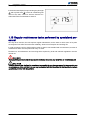
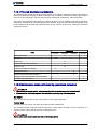
LARGE SPLIT AIR ‑ AIR VITALITY
SERIES Air Conditioners
Installation manual
Ref.: N-27728_EN 0210
Index
Index
1
Installation manual.................................................................................................................. 1
1.1
1.2
1.3
1.3.1
1.3.2
1.3.3
Safety instructions..................................................................................................................
Icons used in this document...................................................................................................
Instructions for storage, transport, loading and unloading of the unit....................................
Disposal of packaging............................................................................................................
Hoisting points........................................................................................................................
Centre of gravity of the unit....................................................................................................
1.4
1.4.1
1.4.2
1.4.3
1.4.4
1.4.5
1.4.6
1.4.7
1.5
1.6
1.6.1
1.6.2
1.6.3
1.6.4
1.6.5
1.6.6
1.6.7
1.6.8
1.7
1.8
1.8.1
1.8.2
1.9
1.10
1.10.1
1.10.2
1.10.3
1.10.4
1.10.5
1.10.6
1.11
1.11.1
1.12
1.13
1.13.1
Technical data........................................................................................................................ 5
Test conditions and correction factors.................................................................................... 5
Limits of use........................................................................................................................... 7
Technical and physical data................................................................................................... 7
Electrical specifications.......................................................................................................... 8
Rated features...................................................................................................................... 10
Options and accessories...................................................................................................... 11
VIR units with auxiliary resistor............................................................................................ 12
Indoor and outdoor unit combinations.................................................................................. 13
Measurements, clearances and accesses........................................................................... 14
Minimum clearance.............................................................................................................. 14
General dimensions, VIR 25A.............................................................................................. 15
General dimensions, VIR 40A.............................................................................................. 16
General dimensions, VIR 45A, VIR 60A............................................................................... 17
General dimensions, VIR 75A, VIR 90A............................................................................... 18
General dimensions and accesses (VAC-VAH 20A25A30A models).................................. 19
General dimensions and accesses (VAC-VAH 40A45A60A models).................................. 20
General dimensions and accesses (VAC-VAH 75A90A models)......................................... 21
Sensible cooling capacities, VAH (Heat pump).................................................................... 22
Specifications table.............................................................................................................. 23
Rated flows for the indoor unit.............................................................................................. 23
Features of the indoor fan gear standard and with high-speed kit....................................... 24
Outdoor fan features............................................................................................................ 26
Instructions for installation and connection of the unit......................................................... 27
Characteristics of the location.............................................................................................. 27
Characteristics of the facility where the unit will be installed................................................ 28
Specifications for the foundation or anchoring of the unit.................................................... 28
Characteristics of utility provider connections...................................................................... 28
Unit refrigerant connection................................................................................................... 28
Preparation and connecting to the various utilities............................................................... 30
Instructions for starting up the unit....................................................................................... 32
Electrical checks................................................................................................................... 32
Unblocking the unit safely in case of breakdown................................................................. 33
Regular maintenance tasks performed by specialised personnel........................................ 34
Planned Maintenance Schedule........................................................................................... 35
2
2
3
3
3
4
i
Index
1.13.2
1.14
Maintenance tasks performed by specialised personnel...................................................... 35
Unit sound power level indication (Lw in dB A).................................................................... 36
2
Unit installation data.............................................................................................................. 39
2.1
2.2
List of tests for unit start-up.................................................................................................. 40
Start-up Data........................................................................................................................ 41
3
Wiring diagrams ................................................................................................................... 45
3.1
3.2
3.3
3.3.1
3.4
3.5
Micro switch configuration....................................................................................................
Fault table............................................................................................................................
Incidents...............................................................................................................................
Test button...........................................................................................................................
DPC-1 thermostat................................................................................................................
Unit wiring diagrams.............................................................................................................
ii
46
47
47
49
49
50
1
Installation manual
1
1.1
Installation manual
Safety instructions
1.1 Safety instructions
This document contains the necessary information for the safe and efficient transportation, assembly
and installation of the air conditioning unit. This guarantees the condition of the unit and its operating
safety.
Only an authorised company may assemble the air conditioning unit.
ATTENTION
Only authorised companies with the appropriate technical resources and suitably trained personnel may
install the air conditioning unit.
CAUTION
The specialists responsible for installing the air conditioning unit must make sure they have all of the
information and knowledge required to correctly install, test and deliver the unit. Johnson Controls Inc.
shall not be considered responsible for any damage caused by installation of the unit that is no consistent
with that described in this document or others specifically provided with the unit.
During regular equipment installation, the fitter must pay special attention to certain situations in order
to prevent injuries or damage to the unit.
Situations that could jeopardise the safety of the fitter or that of others nearby or that could put the unit
itself at risk are clearly indicated in this manual.
A series of special symbols are used to clearly identify these situations.
Pay careful attention to these symbols and to the messages following them, as your safety and the safety
of others depends on it.
1.2 Icons used in this document
•
•
DANGER
The text following this symbol contains information and instructions relating directly to your safety
and physical wellbeing.
Not taking these instructions into account could lead to serious, very serious or even fatal injuries to
you and others in the proximities of the unit.
Information can also be found on safe procedures during unit handling. This will help reduce the risk of
accidents.
•
•
•
CAUTION
The text following this symbol contains information and instructions relating directly to your safety
and physical wellbeing.
Not taking these instructions into account could lead to minor injuries to you and others in the prox‐
imities of the unit.
Not taking these instructions into account could lead to unit damage.
Information can also be found on safe procedures during unit handling. This will help reduce the risk of
accidents.
•
•
2
NOTE
The text following this symbol contains information or instructions that may be of use or that is worthy
of a more thorough explanation.
Instructions regarding inspections to be made on unit parts or systems may also be included.
Installation manual
Instructions for storage, transport, loading and unloading of the unit
1
1.3
1.3 Instructions for storage, transport, loading and unloading of
the unit
CAUTION
Outdoor units must be moved and stored vertically to prevent oil from leaking from the compressor.
Delivery inspection
The unit should be carefully inspected for visible damage or abnormalities as soon as it is received.
Any abnormalities or damage to the unit should be communicated to both the transportation and insur‐
ance company in writing.
Storage instructions
The unit should be stored in a place suitable to the purpose (warehouse or similar), protected from the
weather, water, humidity and dust.
Cover the unit with a canvas of a suitable size.
The unit should be appropriately protected from knocks and dust, ensuring the protective parts it was
supplied with remain in place. Where these are not in place, establish the necessary protection and
barriers to keep vehicles or fork-lift trucks away.
Transport, loading and unloading of the unit
The units should only be handled by personnel from the company responsible for their installation.
Transport of the unit should be in such a manner that no damage is caused by faulty or inadequate
mooring to the bed or body of the vehicle.
Where necessary, protect all of the edges of the unit against knocks and scratches and moor it to the
bed or body of the vehicle using suitable textile belts or slings to keep it perfectly still.
Loading and unloading the unit from a truck or trailer should be on flat, solid ground using an appropriate
crane with sufficient capacity.
1.3.1 Disposal of packaging
The packaging is recyclable. Dispose of it in the appropriate place or take it to an appropriate collection
centre. Respect the regulations in force for this type of waste in the country where the unit is being
installed.
Packaging remains must be correctly disposed of. Improper disposal of packaging generates environ‐
mental problems that affect human life.
1.3.2 Hoisting points
The points designed for hoisting the unit are located on the beams on its base.
Before hoisting the unit, check that the cables or slings are firmly hooked to these points and make sure
the crane and the cables or slings are capable of lifting the weight.
Place spacers at the top of the unit to prevent the cables or slings from touching it.
Attach guide ropes so that that the unit does not rotate freely.
The cables or slings should be long enough to form an angle of over 45º to the horizontal plane. Hoist
the unit keeping it in a horizontal position.
DANGER
There should not be onlookers within a radius of 10 m of the unit when it is being hoisted.
3
1
1.3
Installation manual
Instructions for storage, transport, loading and unloading of the unit
1.3.3 Centre of gravity of the unit
1. Centre of gravity.
2. End of the outdoor coil.
Centre of gravity values table
NOTE
All measurements in mm.
4
Models
VACVAH 20A
VACVAH 25A
VACVAH 30A
VACVAH 40A
VACVAH 45A
VACVAH 60A
VACVAH 75A
VACVAH 90A
A
441
441
441
813.5
813.5
813.5
813.5
813.5
B
500
500
500
510
510
510
785
785
C
1354
1354
1354
1453
1453
1453
2099
2099
D
882
882
882
1627
1627
1627
1627
1627
Installation manual
Technical data
1
1.4
1.4 Technical data
1.4.1 Test conditions and correction factors
Test conditions
Voltage
400
Length of
connection
pipes [m]
7,5
Summer
Ext. temp. ºC
Winter
Int. temp. ºC
Ext. temp. ºC
Int. temp. ºC
DB
TH
DB
TH
DB
TH
DB
TH
35
24
27
19
7
6
20
12
Correction factors for cooling capacities
Cooling capacity correction factors for different air flows to the nominal flows in the indoor coil
% Flow
80
90
100
110
120
130
Total capacity
0,96
0,98
1
1,016
1,032
1,046
Sensible capacity
0,945
0,973
1
1,038
1,075
1,118
Comp. absorbed power
0,98
0,99
1
1,009
1,017
1,025
Cooling capacity correction factors according to length and height between units
H
Vertical distance between the indoor unit and
the outdoor unit
LE
Equivalent length of pipes between the indoor
unit and the outdoor unit (consider a single
line)
A
Outdoor unit above indoor unit
B
Indoor unit above outdoor unit
1
Indoor unit
2
Outdoor unit
5
1
1.4
Installation manual
Technical data
Correction of the actual air inlet temperature on the outdoor coil for different air flows to the nominal flow
% Flow
70
80
90
100
110
120
130
Correction in ºC of the actual air inlet temper‐
ature on the outdoor coil
5
3
1,5
0
-1
-2
-2,5
Correction factors for heating capacities
Indoor unit supply air DB temperature ºC
Indoor unit air DB temperature ºC
14
10
6
0
-8
23
1,2
1,04
0,96
0,77
0,58
20
1,25
1,1
1
0,8
0,69
17
1,3
1,13
1,04
0,83
0,63
Heating capacity correction factors according to length and height between units
H
Vertical distance between the indoor unit and
the outdoor unit
LE
Equivalent length of pipes between the indoor
unit and the outdoor unit (consider a single
line)
A
Outdoor unit above indoor unit
B
Indoor unit above outdoor unit
1
Indoor unit
2
Outdoor unit
Correction of the actual air inlet temperature on the outdoor coil for different air flows to the nominal flow
% Flow
70
80
90
100
110
120
130
Correction in ºC of the actual air inlet temperature
on the outdoor coil
-2
-1,5
-0,5
0
0,5
1
1,2
6
Installation manual
Technical data
1
1.4
1.4.2 Limits of use
Model
Voltage limits
VAC‐
VIR
VAH‐
VIR
VAH‐
VIR
20A
30A
Min.Max V
40A
45A
60A
75A
90A
342457
WB C
Min.Max.
1523
1523
1523
1423
1423
1423
1423
1423
DB C
Min.Max.
2032
2032
2032
2032
2032
2032
2032
2032
(1), (2)
DB C
Min.Max.
1050
1050
1048
1050
1050
1050
1050
1050
Temperature of air in‐
put in indoor coil (3)
DB C
Min.Max.
1027
1027
1027
1027
1027
1027
1027
1027
Outdoor temperature
DB C
Min.Max.
-1020
-1020
-1020
-1020
-1020
-1020
-1020
-1020
Temperature of air in‐
Sum‐ put in indoor coil
mer cy‐
cle
Outdoor temperature
Winter
cycle
25A
(4)
DB dry bulb.
WB wet bulb.
(1)
with the condensation control option, the limit is ‑10 ºC.
(2)
with rated indoor and outdoor air flows.
(3)
the unit is able to run for a short period at temperatures below 10 ºC to raise the temperature of the air in the air conditioned
room to 10 ºC.
(4)
at below ‑10 ºC only the emergency heating resistor or hot water coil (optional) remains connected.
1.4.3 Technical and physical data
OUTDOOR DEVICES
Models
VACVAH
Quantity
Standard rating
Compressors
kW
Degree of protection
20A
25A
30A
40A
1
1
1
1
4,9
6,4
7,9
10,5
1
2
IP
21
Electric power supply
400 3 50
Standard rating
600
No. of fans
Electric power supply
Outdoor fan
1
V ph Hz
Degree of protection
54
Motor speed
rpm
900
Impeller diameter
mm
630
Number of elements
No.
1
1
1
2
2 x 36 3 x 36
3 x 36
3 x 42
2 x 42
m2
1,85
1,85
1,85
1.74 (x2)
Height
mm
1232
1232
1382
1378
Length
mm
1411
1411
1411
1511
Width
Pipe diameters
inches
Area
Dimensions with
packaging
Approximate weight
38"
mm
977
977
977
1727
Net
kg
227
228
250
355
Gross
kg
229
230
252
358
45A
60A
75A
90A
2
2
2
2
2x6
2 x 8.1
2 x 10.7
2 x 13.4
Models
Compressors
230 1 50
IP
Pipes (depth x height)
Outdoor coil
1
VACVAH
Quantity
Standard rating
kW
7
1
1.4
Installation manual
Technical data
Models
VACVAH
45A
Degree of protection
60A
IP
2
Electric power supply
2
V ph Hz
Degree of protection
230 1 50
IP
54
Motor speed
rpm
900
Impeller diameter
mm
630
Number of elements
No.
2
2
2
2
2x42 3x44
3x42 3x44
3x48
3x48
m2
1.74 (x2) 1.95
(x2)
1.69 (x2)
1.95 (x2)
2.47 (x2)
2.47 (x2)
Height
mm
1378 1429
1378 1429
1534
1534
Length
mm
1511
1511
2157
2157
Width
mm
1727
1727
1727
1727
Net
kg
470
483
610
610
Gross
kg
473
488
614
614
Pipes (depth x height)
Pipe diameters
inches
Area
Approximate weight
4
600
No. of fans
Dimensions with
packaging
4
400 3 50
Standard rating
Outdoor coil
90A
21
Electric power supply
Outdoor fan
75A
38"
INDOOR DEVICES
Models
Standard rating
Indoor fan
Indoor coil
V ph Hz
Degree of pro‐
tection
IP
Weight
25A
40A
45A
60A
75A
090
0,75
1,5
1,5
2,2
3
4
400 3 50
55
Motor speed
rpm
Turbine diame‐
ters
mm
320
320x2
320x2
320x2
380x2
380x2
Turbine width
mm
320
240x2
320x2
320x2
380x2
380x2
Number of ele‐
ments
No.
1
1
1
1
1
1
4x21
4x25
4x29
4x29
5x32
5x32
1,40
1,76
1,76
Pipes (depth x height)
Area
Dimensions
with packag‐
ing
kW
Electric power
supply
Pipe diameters
EU3 air filters
VIR
Quantity
1400
inches
m2
38"
0,57
0,84
365x543x24
447x616x24
1,40
No.
Dimensions
3
640x715x24
547x789x24
Height
mm
760
825
925
925
1000
1000
Width
mm
1470
1850
2350
2350
2760
2760
Depth
mm
1020
1020
1020
1020
1020
1020
Net
kg
128
173
223
223
310
312
Gross
kg
152
198
250
250
340
342
1.4.4 Electrical specifications
OUTDOOR DEVICES
Model
8
Compressor
Power supply [V ph (Hz)]
Rated current [A]
Start-up current [A]
VAC 20A VAH 20A
4003 (50)
8,5
74
VAC 25A VAH 25A
4003 (50)
11,8
95
Installation manual
Technical data
1
1.4
Compressor
Model
Power supply [V ph (Hz)]
Rated current [A]
Start-up current [A]
VAC 30A VAH 30A
4003 (50)
15
118
VAC 40A VAH 40A
4003 (50)
19,3
140
VAC 45A VAH 45A
4003 (50)
2 x 12
95
VAC 60A VAH 60A
4003 (50)
2 x 15
118
VAC 75A VAH 75A
4003 (50)
2 x 19
140
VAC 90A VAH 90A
4003 (50)
2 x 25
198
Outdoor fan
Indoor fan
Model
Power supply [V ph
(Hz)]
Power supply [V ph
(Hz)]
Outdoor fan motor
VAC 20A VAH 20A
2301 (50)
VAC 25A VAH 25A
VAC 30A VAH 30A
Indoor fan motor
kW
Rated current
[A]
kW
Rated current
[A]
4003 (50)
0,5
2,4
0,75
1,8
2301 (50)
4003 (50)
0,5
2,4
0,75
1,8
2301 (50)
4003 (50)
0,5
2,4
1,5
2,7
VAC 40A VAH 40A
2301 (50)
4003 (50)
2 x 0.5
2 x 2.4
1,5
2,7
VAC 45A VAH 45A
2301 (50)
4003 (50)
2 x 0.5
2 x 2.4
1,5
3,1
VAC 60A VAH 60A
2301 (50)
4003 (50)
2 x 0.5
2 x 2.4
2,2
4,6
VAC 75A VAH 75A
2301 (50)
4003 (50)
4 x 0.5
4 x 2.4
3
4,7
VAC 90A VAH 90A
2301 (50)
4003 (50)
4 x 0.5
4 x 2.4
4
7
Total max‐ Total maxi‐ Circuit break‐
imum pow‐ mum current er (K Curve)
(1) [A]
er [kW]
(kW)
Power cable
cross-section
(2) [mm2]
Model
Power supply
[V ph (Hz)](3)
Total rated
power [kW]
Total rated
current [kW]
VAC 20A VAH 20A
4003 (50)
6,3
13
9
17
20
4
VAC 25A VAH 25A
4003 (50)
7,2
16
11
20
25
4
VAC 30A VAH 30A
4003 (50)
10
20
14
26
32
6
VAC 40A VAH 40A
4003 (50)
13
27
17
33
40
10
VAC 45A VAH 45A
4003 (50)
14
29
21
37
50
10
VAC 60A VAH 60A
4003 (50)
19
37
26
47
63
16
VAC 75A VAH 75A
4003 (50)
24
48
32
63
80
25
VAC 90A VAH 90A
4003 (50)
29
61
40
73
100
35
(1)
K Curve (DIN, VDE 0660-104).
(2)
Based on copper conductors.
(3)
Main power supply 4003 + N (50)
NOTE
The size of the circuit breaker and the cross-section of the power lines are illustrative and must be
corrected based on site conditions, length between units and current regulations.
INDOOR DEVICES
Model
Power supply [V ph (Hz)]
Standard rating
[kW]
Rated current [A]
Start-up current [A]
Power cable cross-sec‐
tion [mm2]
VIR 25A
4003 (50)
0,75
1,8
8
4 x 1.5
VIR 40A
4003 (50)
1,5
2,7
17
4 x 1.5
VIR 45A
4003 (50)
1,5
3,1
17
4 x 1.5
VIR 60A
4003 (50)
2,2
4,6
22
4 x 1.5
9
1
1.4
Installation manual
Technical data
Model
Power supply [V ph (Hz)]
Standard rating
[kW]
Rated current [A]
Start-up current [A]
Power cable cross-sec‐
tion [mm2]
VIR 75A
4003 (50)
3
4,7
36
4 x 1.5
VIR 90A
4003 (50)
4
7
42
4 x 2.5
(1)
K Curve (DIN, VDE 0660-104).
(2)
Based on copper conductors.
NOTE
The size of the circuit breaker and the cross-section of the power lines are illustrative and must be
corrected based on site conditions, length between units and current regulations.
1.4.5 Rated features
Rated features, cool only models
Outdoor unit
Indoor unit
Summer
Model
Air flow [m3h]
Model
Air flow [m3h]
Cooling power
[W]
Consumption
[W]
E.E.R
VAC 20A
8900
VIR 25A
4590
19100
5601
3,41
VAC 25A
8900
VIR 25A
4590
23000
6991
3,29
VAC 30A
8800
VIR 40A
7500
28800
9600
3,00
VAC 40A
18600
VIR 40A
7500
35100
11622
3,02
VAC 45A
18600
VIR 45A
9000
42900
13533
3,17
VAC 60A
18600
VIR 60A
10500
54000
18600
2,9
VAC 75A
32000
VIR 75A
13000
72300
23099
3,13
VAC 90A
32000
VIR 90A
16000
86100
28605
3,01
Rated features, models with heat pump
Outdoor unit
Indoor unit
Summer
Winter
Air flow [m3h]
Model
Air flow [m3h]
Cooling power
[W]
Con‐
sumption
[W]
VAH 20A
8900
VIR 25A
4590
19100
5601
3,41
21200
4942
4,29
VAH 25A
8900
VIR 25A
4590
23000
6991
3,29
25200
6738
3,74
VAH 30A
8800
VIR 40A
7500
28800
9600
3,00
31900
8417
3,79
VAH 40A
18600
VIR 40A
7500
35100
11622
3,02
41000
12094
3,39
VAH 45A
17900
VIR 45A
9000
42900
13533
3,17
44800
12691
3,53
VAH 60A
17900
VIR 60A
10500
52100
18607
2,8
59400
17069
3,48
VAH 75A
32000
VIR 75A
13000
72300
23099
3,13
81000
22131
3,66
VAH 90A
32000
VIR 90A
16000
86100
28605
3,01
93100
28824
3,23
Model
10
E.E.R
Cooling power
[W]
Con‐
sumption
[W]
C.O.P.
Installation manual
Technical data
1
1.4
1.4.6 Options and accessories
Options and accessories for indoor units
NOTE
Electric resistors and hot water coils cannot be installed at the same time in the same unit.
Model
VIR indoor unit accessories
25A
40A
45A
60A
75A
90A
Indoor electric resistor
10 kW
O
Indoor electric resistor
15 kW
O
Indoor electric resistor
10 kW
O
Indoor electric resistor
20 kW
O
Indoor electric resistor
15 kW
O
O
Indoor electric resistor
30 kW
O
O
Indoor electric resistor
30 kW
O
O
Indoor electric resistor
40 kW
O
O
A
A
O
O
50 m connection cable
A
Hot water coil (20 m)
O
A
Hot water coil (20 m)
A
A
O
O
O
Hot water coil (20 m)
Hot water coil (20 m)
Vertical transformation kit for model
A
Vertical transformation kit for model
A
Vertical transformation kit for model
A
A
Vertical transformation kit for model
A
A
H.S.D H.S.D.M
O
O
O
O
O
O
Economiser (20 m)
A
A
A
A
A
A
50 m communication cable (economiser or
water coil)(1)
A
A
A
A
A
A
O
O
O
O
Soft fan starter
(A) accessory. Supplied separately.
(O) optional. Factory-fitted.
(1)
Where the indoor units is fitted with an economiser and hot water coil, only 50 m of cable is required.
Weights of the options and accessories for indoor units
25A
40A
45A60A
75A90A
Economiser
kg
54
69
78
90
Electric resistor
kg
15
18
20
29
Hot water coil
kg
16
20
37
43
Extra weight for Cu Cu coil
kg
14
19
38
56
VIR Models
11
1
1.4
Installation manual
Technical data
Options and accessories for outdoor units
Model
Accessories for VAC-VAH outdoor units
20A
25A
30A
40A
45A
60A
75A
90A
LAK condensation control
O
O
O
O
O
O
O
O
Soft compressor starter
O
O
O
O
O
O
O
O
(A) accessory. Supplied separately.
(O) optional. Factory-fitted.
Weights of the options and accessories for outdoor units
Models
VAC 20A
VAH 20A, VACVAH 25A
VAC-VAH
30A
VAC-VAH
40A, VAC
45A
VAH 45A,
VAC-VAH
60A
VAC-VAH
75A90A
Condensation control
kg
0,5
0,5
0,5
0,5
0,5
1
Extra weight for Cu Cu coil
kg
31
47
54
70
117
119
1.4.7 VIR units with auxiliary resistor
Circuit breaker
Q1 (1)
Minimum ca‐
ble cross-sec‐
tion (2)
Front surface
A
mm2
m2
Pa
1
20
2,5
0,53
2,9
22
1
25
4
0,53
2,9
10
15
1
20
2,5
0,74
4,9
20
30
2
40
6
0,74
4,9
400 3 50
15
22
1
25
4
0,98
7,1
45A and 60A
400 3 50
30
46
2
50
10
0,98
7,1
75A and 90A
400 3 50
30
46
2
50
10
0,16
7,1
75A and 90A
400 3 50
40
60
2
80
25
0,16
7,1
Model
Electric power
supply
Power
Consumption
VIR
V Ph Hz
kW
A
25A
400 3 50
10
15
25A
400 3 50
15
40A
400 3 50
40A
400 3 50
45A and 60A
(1)
K Curve (DIN, VDE 0660-104).
(2)
Based on copper conductors.
(3)
Considering the rated air flow of the indoor section.
12
Stages
Pressure drop
(3)
Installation manual
Indoor and outdoor unit combinations
1
1.5
1.5 Indoor and outdoor unit combinations
13
1
1.6
Installation manual
Measurements, clearances and accesses
1.6 Measurements, clearances and accesses
1.6.1 Minimum clearance
When installing each unit, clearances should be left for
1 Intake and discharge of air from the outdoor unit.
2 Connection of drain and electricity pipes.
3 Air ducts.
4 Maintenance servicing.
5 Power supply connections.
VAC ‑ VAH unit
VIR unit
14
Installation manual
Measurements, clearances and accesses
1
1.6
1.6.2 General dimensions, VIR 25A
A.
Minimum clearance 600 mm
B.
Minimum clearance 800 mm
1.
Gas connection 1 ‑ 18
2.
Liquid connection 12
3.
Hot water coil accessory connections
4.
Electrical connections
5.
Motor access panel
6.
Filters
7.
Drain pipe (outer diameter 28.5 mm)
15
1
1.6
Installation manual
Measurements, clearances and accesses
1.6.3 General dimensions, VIR 40A
16
A.
Minimum clearance 600 mm
B.
Minimum clearance 800 mm
1.
Gas connection 1 ‑ 18
2.
Liquid connection 58
3.
Hot water coil accessory connections
4.
Electrical connections
5.
Motor access panel
6.
Filters
7.
Drain pipe (outer diameter 28.5 mm)
Installation manual
Measurements, clearances and accesses
1
1.6
1.6.4 General dimensions, VIR 45A, VIR 60A
A.
Minimum clearance 600 mm
B.
Minimum clearance 800 mm
1.
Gas connection 1 ‑ 18 (x2)
2.
Liquid connection 12 (45A), 58 (60A) (x2)
3.
Hot water coil accessory connections
4.
Electrical connections
5.
Motor access panel
6.
Filters
7.
Drain pipe (outer diameter 28.5 mm)
17
1
1.6
Installation manual
Measurements, clearances and accesses
1.6.5 General dimensions, VIR 75A, VIR 90A
18
A.
Minimum clearance 600 mm
B.
Minimum clearance 800 mm
1.
Gas connection 1 ‑ 38 (x2)
2.
Liquid connection 78 (x2)
3.
Hot water coil accessory connections
4.
Electrical connections
5.
Motor access panel
6.
Filters
7.
Drain pipe (outer diameter 28.5 mm)
Installation manual
Measurements, clearances and accesses
1
1.6
1.6.6 General dimensions and accesses (VAC-VAH 20A25A30A models)
1. Electrical connections
B. Liquid pipe diameter
2. Centre of gravity
VAC-VAH 20A25A
12
3. Ø 14 support points
VAC-VAH 30A
58
Weight per support point
C VAC-VAH 20A
.
1030
VAC-VAH 20A25A
VAC-VAH 25A
1030
VAC-VAH 30A
VAC-VAH 30A
1182
D VAC-VAH 20A
.
1230
A. Gas pipe diameter
VAC-VAH 20A25A
1-18
VAC-VAH 25A
1230
VAC-VAH 30A
1-18
VAC-VAH 30A
1382
19
1
1.6
Installation manual
Measurements, clearances and accesses
1.6.7 General dimensions and accesses (VAC-VAH 40A45A60A models)
1. Electrical connections
B. Liquid pipe diameter
2. Centre of gravity
VAC-VAH 40A
58
3. Ø 14 support points
VAC-VAH 45A
2x 12
VAC-VAH 60A
2x 58
Weight per support point
VAC-VAH 40A
C. VAC 40A, 45A, 60A
VAC-VAH 45A
VAH 40A
1178
VAC-VAH 60A
VAH 45A, 60A
1229
A. Gas pipe diameter
20
1178
D. VAC 40A, 45A, 60A
1378
VAC-VAH 40A
1-18
VAH 40A
1378
VAC-VAH 45A
2x 1-18
VAH 45A, 60A
1429
VAC-VAH 60A
2x 1-18
Installation manual
Measurements, clearances and accesses
1
1.6
1.6.8 General dimensions and accesses (VAC-VAH 75A90A models)
1. Electrical connections
2. Centre of gravity
3. Ø 14 support points
Weight per support point
A. Gas pipe diameter
VAC-VAH 75A90A
2x 1-38
B. Liquid pipe diameter
VAC-VAH 75A90A
2x 78
VAC-VAH 75A90A
21
1
1.7
Installation manual
Sensible cooling capacities, VAH (Heat pump)
1.7 Sensible cooling capacities, VAH (Heat pump)
Sensible capacity [W]
Model
Dry fresh air
temp. ºC (DB)
25
VAH 20A VIR 25A
35
45
25
VAH 25A VIR 25A
35
45
25
VAH 30A VIR 40A
35
45
25
VAH 40A VIR 40A
35
45
25
VAH 45A VIR 45A
35
45
25
VAH 60A VIR 60A
35
45
22
Wet supply air temp.
ºC (WB)
Total capacity
Comp. absorbed
power
Dry temp. of supply air to coil ºC (DB)
22
24
27
W
W
W
W
29
W
kW
22
22920
6918
9750
13998
16834
4,12
19,5
20628
10459
13291
17539
20376
4,31
17
19100
14217
17049
19100
19100
4,51
22
21201
6341
9173
13421
16253
4,66
19,5
19100
9899
12731
16979
19100
4,90
17
17572
12856
15688
17572
17572
5,15
22
19100
5699
8531
12779
15611
5,39
19,5
17190
9259
12091
16339
17190
5,64
17
15662
12844
15662
15662
15662
5,88
22
27600
8533
11365
15613
18450
4,28
19,5
24840
12043
14875
19123
21960
4,49
17
23000
15824
18656
22904
23000
4,69
22
25530
7811
10643
14891
17723
4,85
19,5
23000
11344
14176
18424
21256
5,10
17
21160
14157
16989
21160
21160
5,36
22
23000
7009
9841
14089
16921
5,61
19,5
20700
10548
13380
17628
20460
5,87
17
18860
14120
16952
18860
18860
6,12
22
34560
10401
14778
21343
25726
7,06
19,5
31104
15878
20255
26820
31104
7,39
17
28800
21681
26058
28800
28800
7,73
22
31968
9536
13912
20478
24855
7,98
19,5
28800
15037
19414
25979
28800
8,40
17
26496
19027
23404
26496
26496
8,82
22
28800
8572
12948
19514
23890
9,24
19,5
25920
14076
18453
25018
25920
9,66
17
23616
19619
23616
23616
23616
10,08
22
42120
13000
17377
23942
28325
8,23
19,5
37908
18428
22805
29370
33755
8,62
17
35100
24270
28647
35100
35100
9,02
22
38961
11900
16277
22842
27219
9,31
19,5
35100
17364
21741
28306
32683
9,8
17
32292
20990
25367
31932
32292
10,29
22
35100
10680
15057
21622
25999
10,78
19,5
31590
16152
20529
27094
31471
11,27
17
28782
21674
26051
28782
28782
11,76
22
51480
15768
21430
29922
35592
9,83
19,5
46332
22811
28473
36966
42637
10,3
17
42900
30353
36015
42900
42900
10,76
11,12
22
47619
14441
20103
28595
34257
19,5
42900
21525
27187
35679
41341
11,7
17
39468
27594
33256
39468
39468
12,29
22
42900
12966
18628
27121
32783
12,87
19,5
38610
20059
25721
34214
38610
13,46
17
35178
27212
32874
35178
35178
14,04
22
62520
19287
25806
35548
42112
13,48
19,5
56268
27374
33892
43670
50200
14,12
17
52100
36073
42591
52100
52100
14,77
22
57831
17656
24175
33953
40472
15,25
19,5
52100
25792
32313
42091
48610
16,05
17
47932
32428
38947
47932
47932
16,85
22
52100
15846
22364
32142
38661
17,66
19,5
46890
23997
30516
40294
48813
18,46
Installation manual
Specifications table
1
1.8
Sensible capacity [W]
Model
Dry fresh air
temp. ºC (DB)
Total capacity
W
W
W
W
W
kW
17
42722
32222
38741
42722
42722
19,26
25
VAH 75A VIR 75A
35
45
25
VAH 90A VIR 90A
Comp. absorbed
power
Wet supply air temp.
ºC (WB)
35
45
Dry temp. of supply air to coil ºC (DB)
22
24
27
29
22
86760
26856
35684
48926
57767
16,80
19,5
78084
37791
46619
59860
68704
17,60
17
72300
49581
58409
71650
72300
18,40
22
80253
24580
33408
46649
55477
19,00
19,5
72300
35589
44417
57658
66486
20,00
17
66516
45592
54420
66516
66516
21,00
22
72300
22054
30882
44124
52951
22,00
19,5
65070
33083
41911
55152
63980
23,00
17
59286
44214
53041
59286
59286
24,00
22
103320
32112
42331
57660
67894
21,42
19,5
92988
44748
54967
70295
80533
22,44
17
86100
58409
68628
83957
86100
23,46
22
95571
29383
39602
54930
65150
24,23
19,5
86100
42109
52328
67657
77876
25,50
17
79212
53327
63546
78875
79212
26,78
22
86100
26356
36575
51904
62123
28,05
19,5
77490
39108
49327
64656
74875
29,33
17
70602
51983
62202
70602
70602
30,60
1.8 Specifications table
1.8.1 Rated flows for the indoor unit
•
•
•
NOTE
H.S.D High-speed kit.
H.S.D.M High-speed kit with motor included.
The cooling and heating capacities in the corresponding tables are valid for the following rated flows.
For other flows, apply the correction factors of the corresponding table Test conditions and correction
factors , see on page 5 and Limits of use , see on page 7 .
Model
Rated flow
Minimum flow
m3h
m3s
m3h
VIR 25A
4590
1,3
VIR 40A
7500
2,1
VIR 45A
9000
VIR 60A
Available rated pressure of in‐
door fan
Maximum flow
m3s
m3h
m3s
Pa
3600
1
5500
1,5
117
6000
1,7
8300
2,3
118
2,5
7200
2
10800
3
130
10500
2,9
8400
2,3
12600
3,5
137
VIR 75A
13700
3,8
11000
3,1
17500
4,9
125
VIR 90A
16000
4,4
12800
3,6
17500
4,9
175
23
1
1.8
Installation manual
Specifications table
1.8.2 Features of the indoor fan gear standard and with high-speed kit
VIR 25A
Flow m3 h
Ventila‐
tion gear
Code
3600
3900
4250
4590
4900
5200
5500
Ps
P
Ps
P
Ps
P
Ps
P
Ps
P
Ps
P
Ps
P
₋
Standard
₋
172
720
156
790
137
825
117
895
92
965
₋
₋
₋
H.S.D
611991087
267
900
253
980
₋
₋
₋
₋
₋
₋
₋
₋
₋
₋
H.S.D.M
611991088
267
900
253
980
238
1040
222
1100
200
1160
180
1220
158
1290
VIR 40A
Flow m3 h
Ventila‐
tion gear
Code
6000
6500
7000
7500
7800
8000
8300
Ps
P
Ps
P
Ps
P
Ps
P
Ps
P
Ps
P
Ps
P
Standard
₋
153
1070
150
1100
137
1200
118
1305
105
1355
98
1390
85
1440
H.S.D
611991089
242
1280
241
1340
233
1460
217
1585
206
1655
200
1700
188
1760
VIR 45A
Flow m3 h
Ventila‐
tion gear
Code
7200
7800
8400
9000
10500
12000
12600
Ps
P
Ps
P
Ps
P
Ps
P
Ps
P
Ps
P
Ps
P
₋
Standard
₋
150
1375
146
1405
141
1430
130
1490
₋
₋
₋
₋
₋
H.S.D
611991091
203
1575
201
1615
197
1650
188
1720
₋
₋
₋
₋
₋
₋
H.S.D.M
611991090
203
1575
201
1615
197
1650
188
1720
141
2030
65
2400
52
2570
VIR 60A
Flow m3 h
Ventila‐
tion gear
Code
8400
9100
9800
10500
11100
11800
12600
Ps
P
Ps
P
Ps
P
Ps
P
Ps
P
Ps
P
Ps
P
122
2065
90
2270
50
2450
Standard
₋
178
1475
175
1600
160
1750
137
1920
H.S.D
611991092
277
1865
276
2010
266
2170
246
2360
₋
₋
₋
₋
₋
₋
H.S.D.M
611991093
277
1865
276
2010
266
2170
246
2360
234
2510
206
2700
172
2940
VIR 75A
Flow m3 h
Ventila‐
tion gear
Code
11000
12000
12900
13700
15000
16300
17500
Ps
P
Ps
P
Ps
P
Ps
P
Ps
P
Ps
P
Ps
P
97
2450
65
2775
28
3000
Standard
₋
170
1660
156
1830
140
2010
125
2170
H.S.D
611991091
289
2150
282
2380
271
2640
260
2830
₋
₋
₋
₋
₋
₋
H.S.D.M
611991094
289
2150
282
2380
271
2640
260
2830
235
3200
207
3600
175
3930
24
Installation manual
Specifications table
1
1.8
VIR 90A
Flow m3 h
Ventila‐
tion gear
Code
12800
14000
15000
16000
16500
17000
17500
Ps
P
Ps
P
Ps
P
Ps
P
Ps
P
Ps
P
Ps
P
175
3420
161
3575
146
3730
131
3900
Standard
₋
240
2570
222
2910
200
3150
H.S.D
611991095
399
3350
388
3770
374
4090
₋
₋
₋
₋
₋
₋
₋
₋
H.S.D.M
611991096
399
3350
388
3770
374
4090
354
4450
342
4630
328
4830
313
5000
Ps Static pressure available [Pa]
P Consumed power [W]
H.S.D. High-speed kit
H.S.D.M High-speed kit with motor included
Indoor fan high-speed kit (H.S.D and H.S.D.M)
H.S.D and H.S.D.M configuration for VIR units
Fan pulley
Motor pulley
Code
Original diame‐
ter
type
Axis diameter
H.S.D. VIR25A
611991087
125
SPZ (x2)
25
H.S.D.M VIR25A
611991088
140
SPZ (x2)
25
H.S.D. VIR40A
611991089
150
SPZ (x2)
25
H.S.D.
VIR45A75A
611991091
160
SPZ (x2)
25
H.S.D.M VIR45A
611991090
160
SPZ (x2)
25
H.S.D. VIR60A
611991092
140
SPZ (x2)
25
H.S.D.M VIR60A
611991093
140
SPZ (x2)
25
H.S.D.M VIR75A
611991094
160
SPZ (x2)
25
H.S.D. VIR90A
611991095
160
SPZ (x3)
25
H.S.D.M VIR90A
611991096
160
SPZ (x3)
25
Description
Motor
Motor trip switch
Original diameter
type
Axis diam‐
eter
Power [kW]
Quantity
Adjustment (1)
(A)
95
SPZ (x2)
24
1,1
1
3
100
SPZ (x2)
28
3
1
6
95
SPZ (x2)
28
3
1
6
4
1
9,5
006776704
5,5
1
12,5
006776705
Code
006776702
(1) The adjustment is illustrative and must be set to the installation conditions
H.S.D and H.S.M codes for VIR units
Description
High-speed kit
(H.S.D)
Code
VIR 25
611991087
x
611991089
VIR 40
VIR 45
VIR 60
x
611991092
611991088
611991090
611991093
VIR 90
x
611991091
x
x
611991095
High-speed kit with
motor included
(H.S.D.M)
VIR75
x
x
x
x
25
1
1.9
Installation manual
Outdoor fan features
H.S.D and H.S.M codes for VIR units
Description
Code
VIR 25
VIR 40
VIR 45
VIR 60
611991094
VIR75
VIR 90
x
611991096
x
1.9 Outdoor fan features
Model
VAC-VAH 20A VACVAH 25A
VAC-VAH 30A
VAC 45A60A, VAC-VAH
40A
VAH 45A60A
VAC-VAH 75A VACVAH 90A
26
Static pressure available
Air flow
Absorbed power
mm c.d.a
Pa
m3h
m3s
0
0
8900
2,47
532
W
2
20
8200
2,28
554
4
39
7300
2,03
570
0
0
8800
2,44
518
2
20
8700
2,42
520
4
39
8600
2,39
524
0
0
18600
5,16
1040
2
20
16800
4,66
1090
4
39
14900
4,14
1140
0
0
17900
4,97
1073
2
20
16200
4,5
1120
4
39
14500
4
1160
0
0
32000
8,89
2100
2
20
28600
7,94
2200
6
39
26300
7,31
2300
Installation manual
1
Instructions for installation and connection of the unit 1.10
1.10 Instructions for installation and connection of the unit
1.10.1 Characteristics of the location
Location of VIR 25A to 90A indoor units
Locate the indoor unit as close as possible to outdoor walls for easier installation, maintenance and
drainage. Make sure the ceiling fastening where the unit is located will withstand its weight.
The unit must be installed completely horizontally or sloping slightly towards the drain side.
Location of VACVAH 20A to 90A outdoor units
The location of the unit must be studied to ensure a completely satisfactory installation. To do so, the
environmental conditions of the area where the unit is to be installed must be taken into account.
Furthermore, the normal weather conditions should be instrumental in determining the best position of
the unit and the hoods, screens or covers required to ensure its correct working order.
If possible, in warm zones like the southern Europe, the unit should be located on the north or east side
of the building or property.
The location chosen for the unit must provide the condenser with an unlimited air supply.
As well as the technical data given in this document and any others that are applicable, please bear in
mind that the unit has been designed for outdoors installation only.
Where the unit is to be installed at ground level, refer to section Specifications for the foundation or
anchoring of the unit , see on page 28 .
Where the unit is to be installed on the roof of a building or property, make sure that the roof structure
can support the weight of the unit plus that of any optional equipment andor accessories to be fitted.
Special instructions for locations where there is regular snowfall or with ambient temperatures of close
to 0ºC or less
In areas where there is regular or sporadic snowfall, the unit must be elevated above the ground or roof
where it is installed. The height should be enough to prevent the unit, the condenser and evaporator air
inlets and the access to the unit panels from becoming blocked by accumulated snow.
Protection against ice
In areas where the temperature can drop below 0ºC, there must be some kind of additional protection to
prevent the water in the condensate drain pipe from freezing.
Use an electric cord resistor in the drain trap as well as in the drain, where applicable.
In heat pumps, also use cord resistors in the outdoor coil tray to prevent any ice from accumulating.
Special instruction for locations with high ambient temperatures
In areas where the ambient temperature is over 43ºC, the unit must not be located in direct sunlight and,
therefore a specific sunshade will be required.
The installation of a special sunshade over the unit must not effect the air flow required by the unit to
work correctly. See Minimum clearance , see on page 14 .
27
1
Installation manual
1.10 Instructions for installation and connection of the unit
1.10.2 Characteristics of the facility where the unit will be installed
Indoor unit air ducts
The air duct installation where the unit is to be installed must be formed by a closed return duct system.
The additional installation of economisers or outdoor air intakes is not excluded.
To reduce operating noise, the supply and return air duct connections on the unit must be made using
flexible joints.
The supply and return air duct systems must be designed for the air flow requirements of the installation.
The ducts should not be sized based on the supply and return air connection sizes of the unit.
Hatches should be installed on each discharge duct bypass and where access is planned for cleaning
and replacement of filters.
1.10.3 Specifications for the foundation or anchoring of the unit
Where the unit is to be installed at ground level, the characteristics of the ground it will sit on must be
taken into account.
Characteristics, such as acceptable surface firmness, must be suitable for the foundation the unit re‐
quires.
1.10.4 Characteristics of utility provider connections
In general, the different connections required by the unit are made following the shortest route possible.
Under no circumstances may any local or national regulations be contravened when performing the
preparatory work for service connections.
NOTE
For further information on this subject, always keep the current regulations for the country where the unit
is being installed at hand.
•
•
CAUTION
Before the connection work, possible losses of flow, temperature and voltage drops, etc. that might
affect the distances between planned connection points and the unit must be taken into account.
As a result, each connection must be sized accordingly.
1.10.5 Unit refrigerant connection
The indoor and outdoor units are connected by refrigerant pipes that form a sealed refrigerant circuit.
Pipes to be used
CAUTION
Do not leave compressors or dehydrator filters exposed.
Use K or L-type cooling quality copper pipes, SASTMB88.
The pipes must be sealed and insulated until they are connected to the units.
The pipe insulation must be made of a suitable material with a minimum thickness of 8 mm to avoid
condensation and minimum temperature loss due to radiation.
Connection pipe installation
DANGER
Do not carry out work outdoors in the event of adverse weather conditions
CAUTION
Do not use stripping products on Cu ‑ Cu joints.
28
Installation manual
1
Instructions for installation and connection of the unit 1.10
Use rods with a low melting point and a minimum silver content of 5% when welding the pipes. During
this process, there must be a current of dry nitrogen inside the pipe to prevent rust and scale from forming
that would damage the welding and, therefore, affect the watertightness of the circuit.
•
•
NOTE
The connection pipes between units must be as short as possible.
No drain traps are necessary where connecting piping specifications are met.
Cooling layout
The refrigerant pipes must be connected to the units using pipe flaring.
As indicated in the diagram, a dehydrator filter must be fitted (one or two, depending on model) on the
liquid pipe of the installation.
1
2
3
4
5
6
7
8
9
10
11
12
13
14
15
16
Indoor coil
Check valve
Expansion valve
Service valve
Suction accumulator
Liquid sight glass
Expansion valve
Check valve
Liquid sensor
Outdoor air sensor
Outdoor coil
4-way reversing valve.
Discharge sensor
Compressor
Suction sensor
Dehydrator filter (obligatory in the installation)
Vacuum and dehydrating
The presence of air and dampness in the cooling circuit must be completely eliminated to avoid
• Damage to the compressor and other parts of the cooling circuit.
• A drop in unit performance.
• Capillary blocking due to freezing.
• Unwanted high pressure increases.
• Increased electricity consumption.
NOTE
Prior to the vacuum process, nitrogen gas can be swept through the system to remove most of the
dampness and other contaminants in the cooling circuit. The vacuum should be broken on several oc‐
casions using nitrogen to ensure dampness is eliminated.
The vacuum is ensure in each cooling circuit as follows
29
1
Installation manual
1.10 Instructions for installation and connection of the unit
1 Connect the vacuum pump to the service valves
-1- on the installation and connect the service
manometers to the valve stems (¼ valves) -2- in
the circuit.
2 Open the stopcocks on the service valves and the
vacuum pump.
3 Activate the vacuum pump.
4 Vacuum to at least 50 microns.
5 Detect leaks.
1.10.6 Preparation and connecting to the various utilities
Electricity. Power and control
POWER LINE
Power must be supplied to the unit through a specific electricity supply line with an exclusive power
control and differential breaker, installed in line with national and local regulations.
NOTE
For further information on this subject, always keep the current regulations for the country where the unit
is being installed at hand.
Make sure that the electricity supply line has enough capacity to power the unit. Its length, the cable
diameter and their protection (cover or jacket) should be appropriate for the unit.
Use a multimeter to check that the supply voltage re‐
mains within the accepted limits.
To install the power cable, loosen the closures -1- by
14 turn and remove the electrical board panel.
Press the the appropriate openings on the edge of the
unit -1- until they are released.
Fit packing glands to fit the cable and pull the cable
through to the inside of the electrical panel through
the grommets in the tray -2-.
Connect the cable to the input connections indicated
and firmly tighten the set screws. Also consult the
Wiring Diagrams.
NOTE
The complete wiring diagram for the unit is attached
30
Installation manual
1
Instructions for installation and connection of the unit 1.10
to the inside of the electrical panel.
The electrical panel is fitted with a phase detector to ensure the electrical connection follows the se‐
quence of phases R-S-T. Where the connection does not respect this sequence, the electronic control
circuit remains disconnected and the unit will not start.
To correct the phase sequence, change the position of two of the three unit power cables on the input
terminals.
CONTROL LINE
Passing the power and control cables through the
front of the unit.
Press the the appropriate openings on the edge of the
unit -1- until they are released.
Fit packing glands to fit the cable and pull the cable
through to the inside of the electrical panel through
the grommets in the tray -2-.
Connect the cable to the terminals indicated and firm‐
ly tighten the set screws. Also consult the wiring dia‐
grams for the unit and Wiring diagrams , see on page
31 .
NOTE
The complete wiring diagram for the unit is attached to the inside of the electrical panel.
THERMOSTAT CONNECTION
The outdoor unit and the thermostat are connected by
means of a 10-pin x 0.22 mm2 shielded communica‐
tion cable. Connect the cable to the terminals indica‐
ted and firmly tighten the set screws. Also consult the
wiring diagrams for the unit and Wiring diagrams ,
see on page 31 .
Wiring diagrams
1.
Power connection
2.
Thermostat connection
A.
Main power supply
B.
Outdoor unit
C.
Contactor
D.
Indoor fan motor (star connection)
E.
Outdoor unit terminal strip
F.
DPC-1 thermostat
G.
10-pin shielded communications cable x 0.22
mm2
31
1
Installation manual
1.11 Instructions for starting up the unit
Condensates. Insulation andor protection of ducts
Condensates should be released by means of a specific installation in line with local or national regula‐
tions.
NOTE
For further information on this subject, always keep the current regulations for the country where the unit
is being installed at hand.
Install a drain trap on the exhaust outlet of the unit.
The drain trap must have an access register -1- to
facilitate emptying and cleaning when necessary.
Lay the condensate drain pipe from the connection at the bottom of the unit to a nearby drain.
•
•
NOTE
The condensate drain pipe should be at a minimum gradient of 2% (2 cm of drop for each metre in
length).
The condensate drain pipe must be correctly insulated.
Protection against ice
In areas where the temperature can be 0ºC or less, there should be some kind of additional protection
to prevent the water contained in the condensate drain pipe from freezing.
An electric heater (wire heater) should be installed in the drain trap and in the condensate drain pipe.
For units with heat pumps, electric heaters must also be installed in the outdoor coil tray to prevent
possible ice accumulation.
1.11 Instructions for starting up the unit
1.11.1 Electrical checks
•
•
DANGER
All side panels except for that of the electrical box, must be fitted, closed and secured with their
corresponding locks before turning the general switch on the unit.
The unit has a remote control, which means that the fan turbine may start unexpectedly.
CAUTION
Loose connection terminals produce overheating of cables and terminals. The unit will work incorrectly
and there is a risk of fire.
Check that the cables are firmly secured to their connection terminals.
CAUTION
Do not start the unit until all installation work has been completed.
32
Installation manual
1
Unblocking the unit safely in case of breakdown 1.12
Initial connection of the unit
Once all of the planned accessories are installed, and before starting the unit, its general switch on the
installation must be turned on.
Press the "Test" button for two seconds so that the unit recognises the installed accessories. When the
recognition process is complete, the red pilot light switches off.
YKN2 Open control board
The unit control software is in the YKN2 Open control board. The control algorithm can be configured or
changed by
• The position of the micro-switches.
• The connection of accessories detected by the board.
The control board indicates the faults detected by
means of the red V3 LED on the board or the fault
codes indicated on the DPC-1 thermostat.
NOTE
For further information, see the technical information
on the YKN2 Open control board.
Rotational direction of Scroll compressors
The Scroll compressors and the fans only operate correctly if they rotate in the correct direction. All of
the motors and compressors in the unit are connected so that they rotate correctly.
If the compressors are not connected correctly and are rotating in the wrong direction
• The compressor will not compress.
• Operating noise will be abnormal.
• Electricity consumption (A) will be low.
• They overheat.
1.12 Unblocking the unit safely in case of breakdown
•
•
DANGER
All side panels except for that of the electrical box, must be fitted, closed and secured with their
corresponding locks before turning the general switch on the unit.
The unit has a remote control, which means that the fan turbine may start unexpectedly.
To unlock the unit, see "Restarting the air conditioning unit in the case of damage" in the User Manual.
33
Installation manual
1
1.13 Regular maintenance tasks performed by specialised personnel
If the thermostat display keeps showing the pilot light
-1- and any fault code -2- or if the air conditioning unit
does not not start, contact a Johnson Controls Inc.
Authorised Technical Assistance Service.
1.13 Regular maintenance tasks performed by specialised per‐
sonnel
Like any other machine, the unit requires regular maintenance, as the wear to which some of its parts
are subjected can effect its mechanical reliability, electrical consumption and working life.
In order to keep the unit in similar working order to when it was installed and commissioned, a series of
maintenance tasks must be performed every so often.
Furthermore, all maintenance and servicing tasks required by local and national regulations must be
carried out.
DANGER
Only qualified personnel with the appropriate technical resources may install the air conditioning unit.
CAUTION
Johnson Controls Inc. shall not be considered responsible for any damage caused by inappropriate use
or maintenance of the unit that is in any way inconsistent with that described in this document or others
specifically provided with the platform.
34
Installation manual
1
Regular maintenance tasks performed by specialised personnel 1.13
1.13.1 Planned Maintenance Schedule
The following table shows the recommended frequency for regular maintenance tasks. Depending on
the environmental and working conditions where the unit is installed, maintenance tasks may be carried
out more or less frequently. The units must undergo all planned maintenance, without exception.
The person responsible for the building or property where the unit is installed must ensure that these
inspections are performed at the appropriate time. Likewise, this person should keep and maintain a log
book reflecting both planned and unplanned work by the Johnson Controls Inc. Authorised Technical
Assistance Service.
Task
Frequency
1 month
Belts (indoor fan)
Air filters
2 months
Annual
X
X
Indoor coil
X
Condensate tray and drain trap
X
Outdoor coils
X
Outdoor air intake (accessory)
6 months
X
Refrigerant circuit
X
Electrical and mechanical operation
X
Integrity of the unit structure and components
X
Hot water coil (accessory)
X
1.13.2 Maintenance tasks performed by specialised personnel
•
•
DANGER
The unit has a remote control, which means that the fan turbine may start unexpectedly.
Disconnect the electricity supply to the unit before removing any of its side panels.
Air filters
Wash once removed from the unit, sliding them out from their guide rails.
Indoor coil
Visually inspect the indoor coil when performing air filter maintenance.
The complete surface of the fins must be kept clean. If they need to be cleaned, use a soft brush or a
vacuum cleaner, taking special care not to damage the fins.
DANGER
Never use a water hose to clean the indoor coil compartment.
35
1
Installation manual
1.14 Unit sound power level indication (Lw in dB A)
Condensate tray and drain trap
Remove all dirt and residue accumulated in the condensate tray.
Check that neither the condensation outlet nor the drain trap is blocked.
Check that the condensate (water) has been correctly released to the outside.
Fill the drain trap with water if required (prime it).
Outdoor coils
The complete surface of the fins must be kept clean. If they need to be cleaned, use a soft brush or a
vacuum cleaner, taking special care not to damage the fins.
Given that they are exposed to the outdoors, the fins can accumulate a lot of dirt and grime (dust, soot,
sand, etc.). To clean the fins more thoroughly, use water with a neutral detergent (e.g. washing-up liquid).
Clean from the inside out and from top to bottom.
Cooling Circuit
Before the start of each season when the unit is in use, a thorough check of the refrigerant circuit must
be made, including operating pressures, controls and temperature rises, etc.
Electrical and mechanical operation
Before the start of each season when the unit is in use, check the consumption (in amps) of all motors,
the condition of the electrical connections and the correct working order of the safety and protection
systems.
The motor bearings for both the indoor and outdoor fans are permanently lubricated and do not need
additional lubricant during maintenance.
Condition of the unit structure and components
Check the correct condition of the unit structure and outdoor components for knocks, dents, scratched
paint or rust. Check that screws are properly secured and the condition of leak-proof seals and panel
locks and make sure they close properly.
Hot water coil (accessory)
Before the start of each season when the unit is in use, check the level of water in the system, that air
has been purged from the coil and that the controls work properly.
Depending on the climate where the unit is installed, the mix of anti-freeze and water must be checked.
1.14 Unit sound power level indication (Lw in dB A)
Octave band sound spectrum dB(A), outdoor
VACVAH models
20
25
30
40
45
60
75
90
125 Hz
55,5
60,6
63,3
63,5
66
66
66,9
71,9
250 Hz
63,9
63,8
66,2
68,5
70,6
70,6
69,8
71,2
500 Hz
66,4
67,6
69,4
71,8
72
72
73,4
73,2
1,000 Hz
69,3
70,8
72
73,3
73
73
76,1
76
2,000 Hz
64,2
65,6
66,9
68,7
67,8
67,8
70,4
71
4,000 Hz
58
60,9
62,4
63,5
61,9
61,9
63,3
64,1
8,000 Hz
63,3
56,2
53,9
56,6
54,9
54,9
57,1
58,3
Sound power level Lw dB A
71,6
73
76,2
77,5
77,6
77,6
79,1
79,5
Octave band sound spectrum dB(A), indoor
VIR Models
25
40
45
60
75
90
125 Hz
63,7
68,6
73,9
75,5
67
68,6
250 Hz
63,7
70,1
73,5
75,1
70
71,6
36
1
Installation manual
Unit sound power level indication (Lw in dB A) 1.14
VIR Models
25
40
45
60
75
90
500 Hz
69,8
73,8
74,5
76,1
73,8
75,4
1,000 Hz
70,6
74,8
77,2
78,8
74
75,6
2,000 Hz
68,7
75,1
77,1
78,7
74,6
76,2
4,000 Hz
64,9
70,5
72,5
74,1
73,7
75,3
8,000 Hz
55,8
62,3
65
66,6
67,5
69,1
Sound power level Lw dB A
75,4
81,3
82,7
84,3
81,5
83,1
NOTE
Where the sound pressure value of 63 Hz is required, between 0 and 10 dB will be added to the sound
pressure value at 125 Hz
37
2
Unit installation data
2
2.1
Unit installation data
List of tests for unit start-up
Please complete the following data to register the full details of the installation and the start-up inspection.
Complete the blank fields or mark the appropriate box, as applicable.
2.1 List of tests for unit start-up
Please complete the following forms to register the full details of the installation and the start-up inspec‐
tion.
Complete the blank fields or mark the appropriate box, as applicable.
Company performing installation
Company performing installation
Installing technician
Name project number
Location of the unit
Address of the unit location
Person in charge of the building or
property where the unit is installed
Installation work start date
Unit model number
Unit serial number
Plate and version
Thermostat, model and version
General inspection of the unit
Visual appearance
Levelling of the unit
Check the unit for transport, loading and unloading damage
Unit installed with sufficient clearance
Check the circuit for the presence of oil (significant refrigerant leaks).
Terminals and connections correctly secured in the control panel and accessories
Air filters installed
Condensate drain pipe and drain trap installed correctly
Thermostat and connection cabling installed correctly
Air duct installation complete and correct
Accessories and planned options installed (if applicable)
Inspection of the air supply fan
Drive belt and pulleys aligned and correctly fastened
Drive belt tension correctly adjusted
Verification of direction of rotation
Inspection of compressors
Verification that direction of rotation is correct
40
Unit installation data
Start-up Data
2
2.2
2.2 Start-up Data
Electrical data
Rating plate
Actual
Power supply
Control voltage
Fan consumption (A)
Consumption of condenser fan 1 (A)
Consumption of condenser fan 2 (A)
Consumption of compressor 1 (A)
Consumption of compressor 2 (A)
Check specifica‐
tions in the Installa‐
tion Manual
Consumption of supply fan (A)
Electric heater 1 (Optional)
Electric heater 2 (Optional)
Cool and heat modes
Refrigerant circuit. Compressor 1
Mode
Value
Subcooling (min. 8 K, max. 18 K)
C
Subcooling (min. 4 K, max. 10 K)
C
Liquid pressure _____ bar
Liquid temperature _____ C
Suction pressure _____ bar
Suction temperature _____ C
Complete liquid line checked in sight glass
Correct oil level checked in sight glass
Refrigerant circuit. Compressor 2
Mode
Value
Subcooling (min. 8 K, max. 18 K)
C
Subcooling (min. 4 K, max. 10 K)
C
Liquid pressure _____ bar
Liquid temperature _____ C
Suction pressure _____ bar
Suction temperature _____ C
Complete liquid line checked in sight glass
Correct oil level checked in sight glass
Air flow values
m3 h
Design
Measured
41
2
2.2
Unit installation data
Start-up Data
Air temperature
Mode (cool or heat)
Temperature (C)
Outdoor air
Supply air
Return air
Indoor air mix (if economiser is fitted)
Options
Heating mode (hot water coil)
Air temperature
Capacity _____ (kW)
Temperature (C)
Supply air (at 100 %)
Return air
Hydraulic circuit
Temperature (C)
Pressure (bar)
Water inlet
Water outlet
Others
Outdoor fan 1
Outdoor fan 2
Indoor fan
Belts
Economiser
42
Type or model
Surge protection adjusted
Type or model
Surge protection adjusted
Type or model
Surge protection adjusted
Type or model
Minimum outdoor air setting
Unit installation data
Start-up Data
2
2.2
Notes and observations
Notes and observations
____________________________________________________________________________________
____________________________________________________________________________________
____________________________________________________________________________________
____________________________________________________________________________________
____________________________________________________________________________________
____________________________________________________________________________________
____________________________________________________________________________________
____________________________________________________________________________________
____________________________________________________________________________________
____________________________________________________________________________________
____________________________________________________________________________________
____________________________________________________________________________________
____________________________________________________________________________________
Installed by
Name
Date and signature
43
3
Wiring diagrams
3
3.1
Wiring diagrams
Micro switch configuration
3.1 Micro switch configuration
The micro switches are used to establish the following configurations:
ATTENTION
In order to update the new configuration of the micro switches the power supply has to be shut off
MICRO SWITCH CONFIGURATION
Number
1/2
3
4
5
6
7
8
46
Status
Description
OFF/OFF
Defrosting time 0'
ON/OFF
Defrosting time 30'
OFF/ON
Defrosting time 60'
ON/ON
Defrosting time 90'
ON
Crossed coils
OFF
Independent coils
ON
Selection of 2 compressors (tandem) ‑ 1 circuit
OFF
Selection of 1 compressor ‑ 1 circuit
ON
Cold selection
OFF
Heat pump selection
ON
4-way valve active in heat
OFF
4-way valve active in cold
ON
Receives signal B from thermostat (active in heat)
OFF
Receives signal O from thermostat (active in cold)
ON
Fan enabled during defrost
OFF
Fan disabled during defrost
Wiring diagrams
Fault table
3
3.2
3.2 Fault table
The red LED on the YKNOpen electronic board is responsible for showing the state of faults on the unit:
• When the red LED remains off there are no faults in the unit.
• If the red LED does two series of flashes in a constant sequence, there is a fault which must be
checked in the following table:
FAULT TABLE (RED LED)
Red LED flashes
1st Series
1, 2 or 3
4
Description
2nd Series
1
Discharge temperature exceeded
2
High-pressure switch, outdoor fan thermal switch or compres‐
sor module thermal switch
3
Low-pressure switch
4
Indoor fan thermal switch
5
Repeated cold start-up or suction temperature < ‑25℃
1
Gas control 1 or resistor 1 fault
2
Gas control 2 or resistor 2 fault
3
Resistor stage 3 fault
4
Resistor stage 4 fault
5
Fault in economiser or hot water coil (outdoor supply sensor,
water return)
6
Smoke or high temperature detection (accessory) or supply
temperature > 80 C
3.3 Incidents
The green LED on the YKNOpen electronic board is responsible for showing the state of incidents on
the unit:
• If the green LED flashes in a constant sequence, there are no incidents in the unit.
• If the green LED does three series of flashes in a constant sequence, there is an incident which must
be checked in the following table:
NOTE
The first series indicates the affected circuit: one flash for the first compressor, two for the second,
three for the third and four for miscellaneous incidents. A short pause follows. The second and third
series specify the direct cause of the incident.
47
3
3.3
Wiring diagrams
Incidents
INCIDENT TABLE (GREEN LED)
Green Led flashes
1st Ser‐
ies
2nd
Series
3rd Ser‐
ies
Description
Type
1
1
1, 2 or 3
Discharge sensor open or short circuited
Sensors
3
2
1
2
3
4
4
5
48
2
1
2
Incident
Liquid sensor open or short circuited
Intake sensor open or short circuited
Temperature
Repeated defrosting
The discharge temperature is not recovered
1
Supply sensor open or short circuited
2
Return sensor open or short circuited
3
Sensors
Outdoor sensor open or short circuited
4
Water sensor open or short circuited
5
Fault in the enthalpy sensors
1
Signal Y1 or Y2 without signal G
2
3
Thermostat
Signal W without signal B
Signal W without signal G
4
Signal Y2 without signal Y1
1
Heating element thermal switch 1
2
3
Auxiliary heat
Heating element thermal switch 2
Heating element thermal switch 3
4
Heating element thermal switch 4
1
The water coil temperature is not recovered
2
Outdoor temperature too low
3
Temperature
Water coil performing antifrost operation
4
Supply temperature above 55 ºC
5
Supply temperature < 25 ºC with gas
1
Transceiver ID unknown
2
There is at least one accessory not found
3
4
Others
Air quality demand
Dirty filters
5
Presence sensor in unoccupied
6
Intake temperature < 0 ºC, economiser
Wiring diagrams
DPC-1 thermostat
3
3.4
3.3.1 Test button
•
•
•
If the test button is pressed until the green led is activated, certain times are shortened.
If the test button is pressed until the orange led is activated, any fault that has been detected is reset.
If the test button is pressed until the red led is activated, the optional accessories and sensors con‐
nected to the board are identified.
3.4 DPC-1 thermostat
When a fault occurs and there is communication between the unit and the thermostat, the thermostat
alternately displays the time and the fault produced according to the unit fault table.
It also displays other faults related to the thermostat.
MICRO SWITCH CONFIGURATION
Type
Thermostat
Thermostat numbers
Description
9
1
Ambient sensor open or short circuited
9
2
Internal sensor not calibrated
9
3
Communication error
9
4
Fault with AL terminal connected
9
5
S5 digital sensor not detected
9
6
S6 digital sensor not detected
9
7
S7 digital sensor not detected
9
8
S8 digital sensor not detected
9
9
Digital outdoor sensor not detected
49
3
3.5
Wiring diagrams
Unit wiring diagrams
3.5 Unit wiring diagrams
(*)
50
Model
Q2 [A]
Cross-section B [mm2]
F1 [A]
F2 [A] REG.
F3 [A]
20A
20
5x4
16
2,5
3
25A
25
5x4
16
2,5
3
30A
32
5x6
25
3,8
3
35A
40
5 x 10
32
3,8
6
A
S1 configuration on A1 board (VAH models)
O
Crankcase heater
B
S1 configuration on A1 board (VAC models)
P
Indoor fan motor trip switch
C
Thermostat
Q
High and low pressure switch
D
Intake fan [B1]
R
4-way valve 1
E
Liquid sensor [B2]
a
Black connector
F
Discharge sensor [B3]
b
Green connector
G
Outdoor sensor [B4]
c
White connector
H
On-site installation. These components are not supplied by the
manufacturer
d
Yellow connector
I
Shielded cable, 10 x 0.22 mm2
J
Electronic board [A1]
M1
Compressor
K
Accessories connection
M2
Indoor fan
L
YKTOOL connection
M3
Outdoor fan
M
RS-485 connection
M4
Outdoor fan (VAC/VAH 40A models)
N
Cross-section B mm2 Cu
e
Red connector
If the unit has power and the green LED V2 on board A1 is off, check that the sequence of phases
L1, L2, L3 is correct
Wiring diagrams
Unit wiring diagrams
3
3.5
NOTE
Indoor fan M2 is connected on site. See electrical specifications table.
51
3
3.5
Wiring diagrams
Unit wiring diagrams
Model
Q2 [A]
Cross-section B [mm2]
F1 [A]
F2 [A]
F3 [A] REG.
F4 [A]
F5 [A]
45A
50
5 x 10
16
16
3,8
3
3
60A
63
5 x 16
25
25
5,1
3
3
75A
80
5 x 25
32
32
6
6
6
90A
100
5 x 35
32
32
8,7
6
6
A
On-site installation. These components are not supplied
by the manufacturer
M3
B
Cross-section B mm2 Cu
M4
Outdoor fan 1
C
Crankcase heater 1
M5
Outdoor fan 2 (VAC/VAH 75,90A)
D
Crankcase heater 2
M6
Outdoor fan 3
M1
Compressor 1
M7
Outdoor fan 4 (VAC/VAH 75,90A)
M2
Compressor 2
(*)
Indoor fan
If the unit has power and the green LED V2 on board A1 is off, check that the sequence of
phases L1, L2, L3 is correct
NOTE
Indoor fan M3 is connected on site. See electrical specifications table.
52
Wiring diagrams
Unit wiring diagrams
A
S1 configuration on A1 board (VAH models)
M
RS-485 connection
B
S1 configuration on A1 board (VAC models)
N
Indoor fan motor trip switch
C
Thermostat
O
High and low pressure switch 1
D
Intake fan [B1]
P
4-way valve 1
E
Liquid sensor [B2]
Q
High and low pressure switch 2
F
Discharge sensor [B3]
R
4-way valve 2
G
Outdoor sensor [B4]
a
Black connector
H
On-site installation. These components are not supplied
by the manufacturer
b
I
Shielded cable, 10 x 0.22 mm2
c
White connector
J
Electronic board [A1 and A2]
d
Yellow connector
K
Accessories connection
e
Red connector
L
YKTOOL connection
3
3.5
Green connector
53