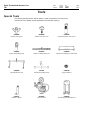
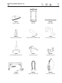
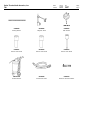
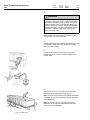
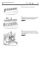
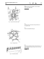
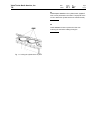
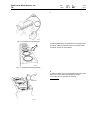
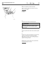
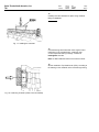
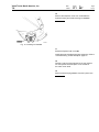
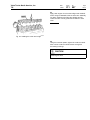
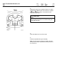
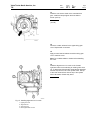
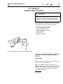
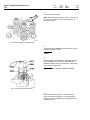
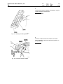
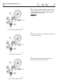
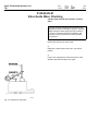
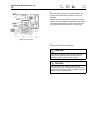
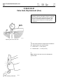
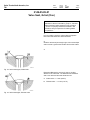
1
TSI
Volvo Trucks North America, Inc.
Greensboro, NC USA
This TSI Service Bulletin replaces TSI Service Bulletin
211–007, “Cylinder Head, D12, D12A, D12B” (11.2001),
publication no. PV776–TSP159904.
Date
Group
No.
9.2003
211 007
Supp.
Page
1(41)
Cylinder Head
D12, D12A, D12B
Cylinder Head
W2002653
Fig. 1: VOLVO D12B Engine
This information covers procedures for repairing the cylinder head of VOLVO D12,
D12A, and D12B engines.
Contents
• “Special Tools” page 2
• “Cylinder Head, Removal” page 5
• “Cylinder Head, Installation” page 12
• “Camshaft Timing, Check and Adjust” page 21
• “Cylinder Head, Overhaul” page 27
• “Cylinder Head, Pressure Test (First)” page 30
• “Valve Guide Wear, Checking” page 34
• “Valve Guides, Replacement (One Cylinder Head)” page 36
• “Valve Seat, Replacement (One)” page 38
• “Valve Seat, Grind (One)” page 40
• “Rocker Arms, Replacement (All)” page 41
PV776-TSP193858
USA13961
Volvo Trucks North America, Inc.
TSI
Date
Group
No.
Page
9.2003
211
007
2(41)
Tools
Special Tools
The following special tools are used to replace or repair components. The tools can be
ordered from Volvo; please use the specified part number when ordering.
9996956
9996966
9998249
Flywheel Turning Tool
Cylinder Liner Press Tool
Protective Sleeve for Unit Injector
9998251
9998255
9998258
Cylinder Head Sealing Plug
Rocker Arm Bridge Lifting Tool
Cylinder Head Adapter (use with Stand)
9998264
J-41503
9996159
Camshaft Removal Tool
Cylinder Head Lifting Fixture
Tap (for 9996161)
9996161
9996662
9998246
Hydraulic Cylinder
Pressure Tester
Valve Spring Removal/Install Tool
Volvo Trucks North America, Inc.
TSI
Date
Group
No.
Page
9.2003
211
007
3(41)
9998256
9998260
9998266
Connection Washer
Press Tool
Sealing Washer
9998335
J-41203
J-41272
Valve Stem Seal Guide Sleeve
Stud Removal and Installation Socket
Front Cover Alignment Tool
J-44457
J-42773
9998270
Cam Shaft Bearing Cap Remover
Cam Gear Timing Tool
Camshaft Locking Tool
J-45242
9996239
9996222
Lifting Bracket
Cylinder Head Lifting Chain
Foot Pump (for 9996161)
Volvo Trucks North America, Inc.
TSI
Date
Group
No.
Page
9.2003
211
007
4(41)
9998259
9999696
9999876
Sealing Washer
Magnetic Stand
Dial Indicator
9998261
9998262
9998263
Drift for Valve Guide
Drift for Valve Guide
Drift for Valve Guide
DB72V700
9996049
9992479
Coolant Extractor
Coolant Drain Hose
Holder for Dial Test Indicator
Volvo Trucks North America, Inc.
TSI
Date
Group
No.
Page
9.2003
211
007
5(41)
Service Procedures
2111-01-01-01
Cylinder Head, Removal
(With VEB or EPG; also with coolant drained off)
(See also “Cylinder Head, Overhaul” page 27.)
You must read and understand the precautions and
guidelines in Service Information, group 21, "General
Safety Practices" before performing this procedure.
If you are not properly trained and certified in this
procedure, ask your supervisor for training before
you perform it.
CAUTION
Observe the greatest possible cleanliness when
working on the cylinder head. Dirt particles in the
fuel and oil channels can cause the unit injectors to
malfunction, and can cause the VEB (if equipped)
to fail or cause engine damage.
Note: The exhaust manifold can remain in place when
removing the cylinder head. Remove the three bolts
holding the thermostat housing. Then, turn the housing
back out of the way to allow enough clearance to remove
the head.
Note: Do not leave the unit injector tubes open with the
injectors removed. Install protective plugs 9998251 to
protect tubes from contaminants.
Special tools: 9996966, 9998249, 9998251,
9998255, 9998258, 9998264
Other special equipment: J–41203, J–44457,
J–41503
1
Remove the electrical wires from the preheater (if
equipped) and the intake manifold sensor and harness
from the intake manifold. If the engine is equipped with
VEB, remove the oil supply pipe. Plug both of the oil
holes in the cylinder head and block.
Volvo Trucks North America, Inc.
TSI
Date
Group
No.
Page
9.2003
211
007
6(41)
2
WARNING
Use a hoist or get assistance when lifting components
that weight 23 kg (50 lb) or more. Make sure all lifting
devices such as chains, hooks, or slings are in good
condition and are of the correct capacity. Make sure
hooks are positioned correctly. Always use a spreader
bar when necessary. The lifting hooks MUST NOT be
side loaded. Failure to follow these warnings may
result in personal injury.
Remove the oil supply line and oil return. Remove
exhaust clamp from turbocharger and shutter housing.
Remove turbo nuts and lift off turbo.
3
Carefully clean around the cylinder head bleed nipple and
the fuel filter bracket drain union located on the right
side of the filter housing.
4
Connect a 5/16” drain hose and open the fuel filter
bracket drain union. Remove the bleed nipple on the
cylinder head.
T2006719
5
Remove the valve cover. The valve cover should be
removed from the exhaust side of the engine.
Note: On WIA, bring the valve cover towards the radiator
to remove. On WG, it is necessary to remove the engine
cover (doghouse).
Note: Be careful to avoid loosening the stud bolts.
Otherwise, the unit injector cable harness and/or the
valve cover can be damaged.
T2006731
Fig. 2: Valve cover
Volvo Trucks North America, Inc.
TSI
Date
Group
No.
Page
9.2003
211
007
7(41)
6
Remove small injector wire from injector and move
aside to prevent damage.
7
Remove the fuel lines from the cylinder head and plug the
connections. Remove the electrical wires for both the
engine coolant temperature sensor and the unit injector.
Note: Pay close attention to the plastic cable ties/straps
and remove any broken pieces to prevent clogging or
damage to any components.
W2000690
Fig. 3: Electrical cable connections
8
Disconnect the connector for the electrical wires on the
upper timing gear cover. Remove the clamp holding the
electrical wires to the cover.
9
Remove the upper part of the timing gear cover.
10
Remove the cam sensor wheel which is mounted on
the outside of the camshaft gear.
11
If the engine is equipped with a VEB, remove the control
valve and pipe. Plug ports and place assembly in a plastic
bag to prevent contamination. To facilitate removal of the
VEB control valve, remove the valve cover stud bolt. Use
Kent-Moore socket J–41203 to remove early style stud
bolts (oval flange). Use a 14 mm deepwell socket for
new style studs (hexagonal flange).
Note: On engines equipped with a VEB, use rubber
bands to hold the VEB slave pistons in place during
rocker arm assembly removal.
J–41203
Volvo Trucks North America, Inc.
TSI
Date
Group
No.
Page
9.2003
211
007
8(41)
12
Loosen all adjustment lock nuts and screws.
T2006777
Fig. 4: Rocker arm shaft bolts
13
Gradually loosen the rocker arm bolts to avoid distorting
the rocker arm shaft. Remove the bolts. Install tool
9998255 and lift off the rocker arm assembly.
9998255
W2002159
Fig. 5: Removing the rocker arm shaft
14
Carefully clean around the unit injectors and remove
them. Make sure that no dirt drops into the unit injector
space in the cylinder head. Install dust cover 9998249 on
the unit injectors.
9998249
W2000716
Fig. 6: Unit injector protector sleeve
Volvo Trucks North America, Inc.
TSI
Date
Group
No.
Page
9.2003
211
007
9(41)
15
Install protective plugs 9998251 in the unit injector
bore in the cylinder head.
9998251
W2000689
Fig. 7: Injector bore protector plug
16
Carefully pull the unit injector wiring harness out of
the cylinder head.
17
Remove the adjustable idler gear.
T2007095
Fig. 8: Idler gear bolts
18
Remove the camshaft cap bolts. Number the caps (1–7)
for the respective bearing housings and remove using
puller J-44457.
J-44457
T2006777
Fig. 9: Camshaft cap bolts
Volvo Trucks North America, Inc.
TSI
Date
Group
No.
9.2003
211
007
Page
10(41)
19
Carefully lift off the camshaft, using tool 9998264.
9998264
T2006783
Fig. 10: Removing the camshaft
20
Remove the cylinder head mounting bolts.
21
Remove the #4 lower bearing housing for the camshaft.
Remove the stud bolt for the valve cover. Use Kent-Moore
socket J–41203 to remove early style stud bolts (oval
flange). Use a 14 mm deepwell socket for new style studs
(hexagonal flange). Install tool 9996239 in the bearing
housing and stud bolt holes.
J–41203, 9996239
22
Install lifting bracket J-41503 on to the cylinder head.
Carefully lift off the cylinder head from the engine. Then,
remove the head gasket from the cylinder block.
J–41503
W0002015
Volvo Trucks North America, Inc.
TSI
Date
Group
No.
9.2003
211
007
Page
11(41)
23
Install adapter 9998258 on the cylinder head. (Applies if
work is to be performed on the head. The purpose of the
tool is to attach the cylinder head to the overhaul stand.)
9998258
24
Install 9996966 to liners to prevent the liner from
loosening the seal when rotating the engine.
9996966
T2007156
Fig. 11: Locking the cylinder liners in place
Volvo Trucks North America, Inc.
TSI
Date
Group
No.
9.2003
211
007
Page
12(41)
2111-02-01-01
Cylinder Head, Installation
(See also “Cylinder Head, Overhaul” page 27.)
You must read and understand the precautions and
guidelines in Service Information, group 21, "General
Safety Practices" before performing this procedure.
If you are not properly trained and certified in this
procedure, ask your supervisor for training before
you perform it.
CAUTION
Observe the greatest possible cleanliness when
working on the cylinder head. Dirt particles in the
fuel and oil channels can cause the unit injectors to
malfunction, and cause the VEB (if equipped) to fail or
cause engine damage.
W2003459
Fig. 12: 1) Remove plug only for engines with Volvo
Engine Brake (VEB)
Note: When installing an exchange cylinder head
on a D12 engine with a Volvo Engine Brake (VEB),
the oil supply plug (shown in illustration) must be
removed prior to installation of the VEB solenoid. In
engines with exhaust pressure governor (EPG), only
the plug must remain in place.
CAUTION
Failure to remove the oil supply plug on a D12 with
Volvo Engine Brake (VEB) exchange cylinder head
will cause camshaft seizure. Severe engine damage
will result.
Special tools: 9996956, 9998251, 9998255,
9998258, 9998264
Other special equipment: 9999708, J–41203,
J–41272, J–42773, J–41503
Volvo Trucks North America, Inc.
TSI
Date
Group
No.
9.2003
211
007
Page
13(41)
1
T2007163
Fig. 13: Cleaning the cylinder head
Clean all gasket and O-ring surfaces of the cylinder head
and block. Make sure all bolt holes in the cylinder head
and block are free of oil and debris.
T2007087
Fig. 14: Cylinder block sealing surface
2
If debris or carbon is in the cylinder head bolt holes, clean
the top of the hole before the threads by using a
17 mm drill. Turn it manually into the hole.
17 mm drill
C2001734
Volvo Trucks North America, Inc.
TSI
Date
Group
No.
9.2003
211
007
Page
14(41)
3
Clean the threads with a M16x2 thread tap.
Note: To remove residue from bolt holes, use chip
vacuum tool PT-2900
M16x2 tap,
PT-2900
C2002611
4
Remove the tools used to hold down the liner.
WARNING
Always wear appropriate eye protection to prevent
the risk of eye injury due to contact with engine
debris or fluids.
5
Clean the cylinder block surface and around the cylinder
liner.
6
Install the new cylinder head gasket to the engine block
and the new rubber seal to the timing gear plate.
Note: Make sure that the seal is correctly positioned
against the timing gear plate.
7
Carefully lift the cylinder head onto the cylinder block.
Remove the lifting tool J–41503.
J–41503
Volvo Trucks North America, Inc.
TSI
Date
Group
No.
9.2003
211
007
Page
15(41)
8
Install the cylinder head bolts and torque-tighten using
proper sequence (see Fig. 15: Cylinder head bolt torque
sequence, page 15) and the following steps:
1 Tighten bolts to a torque of 60 ± 10 Nm (44 ± 7 ft-lb).
2 Check tighten to same torque.
3 Turn bolt 90 ± 5 . Make diagonal mark across
bolt head with a felt-tip pen after turning or use
angle gauge.
4 Turn bolt an additional 90 ± 5 . Make another diagonal
mark across bolt head with felt-tip pen after turning.
T2007004
Fig. 15: Cylinder head bolt torque sequence
Note: Marking diagonal lines across the bolt heads will
help to identify which bolts have been torqued.
Note: O-rings are no longer recommended for use when
installing cylinder head bolts shanks.
9
Cut off the protruding ends of the rubber seal on the
timing gear plate.
10
Position the bearing housings for the camshaft on
the cylinder head.
CAUTION
Make sure that the mating surface under the bearing
housings is clean and the guide pins are not damaged.
If installing a new cylinder head, you must install the
bearing housings supplied with the cylinder head.
11
Coat the bearing shell halves with clean engine oil and
install them in the bearing housings.
T2007126
Fig. 16: Bearing shell halves
12
Remove the 5 bolts fastening the adjustable idler gear
and remove the adjustable idler gear assembly (if it has
not already been removed).
Volvo Trucks North America, Inc.
TSI
Date
Group
No.
9.2003
211
007
Page
16(41)
13
Carefully hoist the camshaft into place using camshaft
lifting tool 9998264.
9998264
T2006783
Fig. 17: Installing the camshaft
14
Coat the bearing shell halves with clean engine oil and
install them in the camshaft caps. Install the caps
on their respective bearing housings. Install and
hand-tighten the bolts.
Note: Do NOT install the bolts for the rocker arm shaft.
15
Set the camshaft to Top Dead Center (TDC), according to
the marking on the camshaft, at the front bearing housing.
W2000936
Fig. 18: Positioning camshaft (rocker arms not installed)
Volvo Trucks North America, Inc.
TSI
Date
Group
No.
9.2003
211
007
Page
17(41)
16
Remove the inspection cover from underneath the
flywheel housing and install cranking tool 9996956.
9996956
T2006672
Fig. 19: Cranking tool installed
17
Rotate the flywheel until it is at 0 .
Install idler gear and adjust gear lash and timing. Refer to
“Camshaft Timing, Check and Adjust” page 21.
18
Carefully route the wiring harness for the unit injectors
into the cylinder head and place on the outside of
the rocker cover studs.
19
Remove protective plug 9998251 from the injector bore.
9998251
Volvo Trucks North America, Inc.
TSI
Date
Group
No.
9.2003
211
007
Page
18(41)
20
Remove each injector from the protector and install new
O-rings. Coat the sealing rings with clean engine oil.
Note: Remove the bore protector and clean the bore
before installing the injector into the bore (9998251)
9998251
21
Install the unit injectors and center them between the
valve springs. Torque-tighten unit injector hold down bolt
as follows:
•
If using new copper sleeve:
•
1 Tighten to 20 ± 5 Nm (15 ± 4 ft-lb).
2 Turn bolt 180 ± 5 .
3 Loosen to “0” Nm
4 Tighten 20 ± 5 Nm (15 ± 4 ft-lb).
5 Turn bolt 60 ± 5 .
If using old copper sleeve:
1
2
Tighten to 20 ± 5 Nm (15 ± 4 ft-lb).
Turn bolt 60 ± 5 .
W2000718
Fig. 20: Unit injector retaining bolt
22
Connect the unit injector electrical wires and torque the
nut to 1 ft-lb (1.36 Nm).
CAUTION
DO NOT OVERTIGHTEN. Hold wires while tightening.
If the screws break, the unit injector must be replaced.
Note: Using torque wrench 9999708, torque-tighten the
nut to 1.4 Nm (12 in-lb). Route the unit injector electrical
wires to the outside of the valve cover bolts.
1 ft-lb (1.36 Nm)
1.4 Nm (12 in-lb)
W2000690
Fig. 21: Unit injector cable connections
Volvo Trucks North America, Inc.
TSI
Date
Group
No.
9.2003
211
007
Page
19(41)
23
Apply clean engine oil to the valve bridges and camshaft
lobes. Using tool 9998255, hoist the rocker arm assembly
into place. Make sure that the valve bridges and the
rocker arms are correctly positioned in relation to each
other.
9998255
T2006820
Fig. 22: Installing the rocker arm bridge
24
Using the crossover pattern, tighten the rocker arm shaft
bolts until the rocker arm shaft bottoms out against
the bearing housings.
CAUTION
Gradually tighten the rocker arm shaft to avoid
distorting the shaft.
Volvo Trucks North America, Inc.
TSI
Date
Group
No.
9.2003
211
007
Page
20(41)
25
T2006777
Fig. 23: Tightening rocker arm shaft and camshaft
together
On engines equipped with VOLVO Engine Brake, reinstall
the VEB control valve at this time. Slide the valve and
pipe into the rocker arm shaft as a unit. Apply Loctite
to the mounting bolt threads and torque the bolts to 33
± 4 Nm (24 ± 3 ft-lb).
Note: Make sure that the flywheel is at 0 and the
camshaft is at TDC according to the marking.
Tighten the rocker arm shaft together with the camshaft,
using the 5-step torque sequence shown below. When
reinstalling a rocker arm shaft that has been loosened
or removed, torque-tighten only the bolts that hold the
rocker arm shaft.
1
2
3
4
0
5
15 ± 5 Nm (11 ±
45 Nm (33 ft-lb)
15 ± 5 Nm (11 ±
45 Nm (33 ft-lb);
Nm (0 ft-lb)
15 ± 5 Nm (11 ±
4 ft-lb); +90 ± 5
4 ft-lb); +90 ± 5
loosen to
4 ft-lb); +90 ± 5
W2003520
Fig. 24: Bearing caps and camshaft/rocker shaft,
tightening sequence, D12, D12A, D12B
26
Install fuel lines to the rear of the cylinder head.
Note: Use new copper washers.
W2000720
Fig. 25: Fuel lines installed
Volvo Trucks North America, Inc.
TSI
Date
Group
No.
9.2003
211
007
Page
21(41)
2154-06-03-02
Camshaft Timing, Check and Adjust
You must read and understand the precautions and
guidelines in Service Information, group 21, "General
Safety Practices" before performing this procedure.
If you are not properly trained and certified in this
procedure, ask your supervisor for training before
you perform it.
Special tools: 9996956, J-41272, J-42773
1
Note: Special tools with part numbers that begin with
“J” are available from Kent-Moore.
Remove the cam sensor
wheel.
2
Install the camshaft alignment tool J–42773 by inserting
the guide pin into the hole under the camshaft drive
gear. Rotate the tool to position the lever against the
drive gear teeth to ensure correct positioning of the
camshaft alignment tool.
3
With J-42773 held in position, set the camshaft as shown.
Note: The camshaft setting must be exactly as illustrated
in the illustration. It is important that the camshaft gear
marking is positioned precisely on both sides of the tool in
a line extending from the center of the camshaft.
J-42773
T2012262
Volvo Trucks North America, Inc.
TSI
Date
Group
No.
9.2003
211
007
Page
22(41)
4
Rotate the flywheel in the opposite direction of rotation
approximately 20 , and then in the direction of rotation
20 to the 0 mark exactly. If you pass the mark,
repeat this entire step.
CAUTION
Final rotation of the flywheel in the opposite direction of
normal rotation will result in an incorrect setting due
to the gear train lash.
W2004266
5
Clean all sealant from front of the head.
6
Install the adjustable idler gear assembly.
Note: The bolts are the single-use “stretch” type and
should not be reused. Pipe sealant should be used on
the center bolt.
Volvo Trucks North America, Inc.
TSI
Date
Group
No.
9.2003
211
007
Page
23(41)
7
W2002245
Insert the 0.10 mm (0.004 in.) feeler gauge on the load
sides of the (A and B) gear teeth.
T2008255
8
Torque the bolts to an initial torque of only 15 ± 3 Nm
(11 ± 2 ft-lb).
Note: An additional 120 ± 5
backlash is confirmed.
is required after the correct
15 ± 3 Nm
(11 ± 2 ft-lb)
9
Check that both feeler gauges have the same
resistance when inserting them and pulling them
out. The correct backlash is 0.05-0.17 mm
(0.002-0.007 in.).
0.05-0.17 mm
(0.002-0.007 in.)
Volvo Trucks North America, Inc.
TSI
Date
Group
No.
9.2003
211
007
Page
24(41)
10
Tighten the bolts an additional
120 ± 5 per the torque sequence shown.
W2002245
11
Re-check camshaft timing. Rotate the engine opposite
the direction of rotation approximately 20 . Continue in
the direction of rotation until the two dots on the cam
gear are equally spaced on both sides of the camshaft
alignment tool, J–42773. Verify that the pointer on
the flywheel is within specifications (2 mm BTDC to 2
mm ATDC).
J–42773
W2004266
12
After the rocker assembly has been torqued in place, use
a dial indicator to perform a final check of the adjustable
idler gear backlash. Correct backlash is 0.05 – 0.17
mm (0.002 – 0.007 in.).
0.05 – 0.17 mm
(0.002 – 0.007 in.)
T2007084
Fig. 26: Checking backlash
Volvo Trucks North America, Inc.
TSI
Date
Group
No.
9.2003
211
007
Page
25(41)
13
Install the cam sensor wheel on the camshaft drive
gear. Install and torque tighten the three bolts to
25 Nm (19 ft-lb).
25 Nm
(19 ft-lb)
T2007096
14
Clean the contact surfaces for the upper timing gear
cover. Replace with a new seal.
15
Apply an even bead of sealant around the timing gear
cover. Install the cover.
Note: Do not allow sealant to harden before installing
the cover.
16
Install the alignment tool J–41272 on the forward
right-hand valve cover stud using an existing valve cover
nut. To attach the left-hand side, thread the bolt (supplied
with the tool) into the hole in the cylinder head. The top
of the cover must be flush with the top of the cylinder
head. Otherwise, oil leaks may result.
J–41272
W2002163
Fig. 27: Installing alignment tool J–41272
1
2
3
4
Upper gear cover
Alignment tool
Valve cover nut
Bolt supplied with J–41272
Volvo Trucks North America, Inc.
TSI
Date
Group
No.
9.2003
211
007
Page
26(41)
17
Draw the cover down evenly until the cylinder head and
cover are aligned. Tighten bolts in the proper sequence
and torque to 33 ± 3 Nm (24 ± 3 ft-lb).
33 ± 3 Nm
(24 ± 3 ft-lb)
18
Measure the cam sensor-to-pole wheel air gap.
Note: Make sure the air gap is between 0.3 – 0.7
mm (0.011 – 0.028 in.).
0.3 – 0.7 mm
(0.011 – 0.028 in.)
19
Connect the electrical cable to the cam sensor on
the cover.
20
Apply an even 2 mm (0.08 in.) bead of sealant around
the intake manifold. Install the intake manifold and
connect the electrical wires.
T2007149
Fig. 28: Intake manifold
CAUTION
The sealant must not harden before installing the
intake manifold. If the engine is equipped with a VEB,
make sure that sealant does not enter the oil channel
as this can negatively affect brake operation.
21
Install the turbocharger; refer to Service Information,
Group 25.
22
Adjust the valves and unit injectors. For the adjustment
procedure, refer to Service Information, Group 23.
Volvo Trucks North America, Inc.
TSI
Date
Group
No.
9.2003
211
007
Page
27(41)
2111-04-04-01
Cylinder Head, Overhaul
CAUTION
Observe the greatest possible cleanliness when
working on the cylinder head. Dirt particles in the
fuel and oil channels can cause the unit injectors to
malfunction, and can cause the VEB (if equipped)
to fail.
One or more of the following procedures also may be
used as reference or included as part of this procedure;
for information, see Service Information, Group 2:
•
•
•
•
•
•
•
Cylinder Compression, Checking
Valve Guide Wear, Checking
Valve Guide, Replacement
Valve Seat, Replacement (One)
Valve, Adjustment
Valve, Grinding
Valve Seat, Grinding
T2006781
Fig. 29: Attaching the cylinder head to the overhaul stand.
Special tools: 9996159, 9996161, 9996222,
9998246, 9998260, 9998355, 9998258,
9998335
Disassembly
1
Attach the cylinder head firmly to the overhaul stand so
that it can be turned if necessary.
Note: It is important that extreme cleanliness be
observed when working on the cylinder head. Dirt and
particles can cause the unit injector to fail. If the engine
is equipped with a VEB, both the brake and engine
functions may be affected.
9998258
Volvo Trucks North America, Inc.
TSI
Date
Group
No.
9.2003
211
007
Page
28(41)
2
Remove the valve bridges.
Note: Mark the bridges and place them in order so that
they can be reinstalled in their original positions on
the cylinder head.
T2007050
Fig. 30: Valve bridges (non-VEB shown)
3
Install pressing tool 9998260 together with the counter
hold which holds the valves.
9998260
4
Install hydraulic cylinder 9996161, with studs 9996159
and drift 9998246, in pressing tool 9998260 using
9996222 hydraulic pump. Press down the valve rotator
and remove the valve locks.
9996159, 9996161, 9996222, 9998246, 9998260
T2006782
Fig. 31: Removing the valve locks
5
Remove the remaining valves in a similar manner.
Place the valves and springs on a rack so that after
testing, they are reinstalled in their original positions in
the cylinder head.
Volvo Trucks North America, Inc.
TSI
Date
Group
No.
9.2003
211
007
Page
29(41)
Assembly
6
Coat the valve stems with clean engine oil. Place the
valves in the valve guides. Position tool 9998335 on the
valve stem and push the seal over the tool until the seal
bottoms out against the valve guide. Install the springs
with regard to whether they are intake or exhaust valve
springs. Carefully press down the springs and install
the valve locks.
Note: Exhaust valves have double springs.
T2006782
Fig. 32: Installing the valve locks
7
Install the valve bridges in their respective positions and
adjust. See Service Information, Group 23, Valve and
Electronic Unit Injector Adjusting.
Volvo Trucks North America, Inc.
TSI
Date
Group
No.
9.2003
211
007
Page
30(41)
2111-06-04-01
Cylinder Head, Pressure Test (First)
(Head removed; thermostat housing and exhaust
manifold removed)
You must read and understand the precautions and
guidelines in Service Information, group 21, "General
Safety Practices" before performing this procedure.
If you are not properly trained and certified in this
procedure, ask your supervisor for training before
you perform it.
CAUTION
Observe the greatest possible cleanliness when
working on the cylinder head. Dirt particles in the
fuel and oil channels can cause the unit injectors to
malfunction, and can cause the VEB (if equipped)
to fail or cause engine damage.
Special tools: 9996662, 9998256, 9998259,
9998266, 960631, 11996, 9998251
1
Install two (2) 960631 plugs and two (2) 11996
copper washers into the fuel pressure and fuel return
connections.
960631
11996
T2007142
Fig. 33: Installing the plugs in fuel system ports
2
Install the injector bore protective plugs 9998251 with
O-rings removed and secure with the injector hold
down from the engine assembly. Hand tighten the
hold down bolt.
DANGER
The injector hold down prevents the injector tube from
being blown from its bore when air pressure is applied.
9998251
W2004233
Volvo Trucks North America, Inc.
TSI
Date
Group
No.
9.2003
211
007
Page
31(41)
3
Install sealing washers 9998259 and 9998266, using the
cylinder head bolts and M16 nuts.
9998259, 9998266
T2007143
Fig. 34: Installing the sealing washers
4
Clean the contact surface and install the connection
washer 9998256 on the thermostat housing position on
the cylinder head.
9998256
T2007153
Fig. 35: Connection washer installed
Volvo Trucks North America, Inc.
TSI
Date
Group
No.
9.2003
211
007
Page
32(41)
5
Before using pressure tester 9996662, connect it to the
shop air supply and set the pressure gauge to 103 kPa
(15 psi) using the reduction valve. Lock the reduction
valve knob (2) with the lock ring.
9996662
W2000715
Fig. 36: Pressure reduction knob
6
Close the shut-off valve (1). Verify that the pressure does
not drop for two minutes.
W2002162
Fig. 37: Shut-off valve knob
7
Make sure that the pressure gauge reduction valve
knob (2) is open (turn counterclockwise).
W2000715
Fig. 38: Pressure reduction knob
Volvo Trucks North America, Inc.
TSI
Date
Group
No.
9.2003
211
007
Page
33(41)
8
Remove the cylinder head from the overhaul stand and
immerse the head in a tank of water heated to 70 C
(160 F).
T2007167
Fig. 39: Cylinder head in tank of water
9
Open the shut-off valve.
10
Turn the reduction valve knob (2) clockwise until the
gauge shows a reading of 50 kPa (7.25 psi). Maintain this
pressure for one minute.
W2000715
Fig. 40: Pressure reduction knob
11
Then, increase the pressure to 160 kPa (23 psi). Secure
the reduction valve knob with the lock ring and close
the shut-off valve. After two minutes, check to see if the
pressure has dropped or if there are air bubbles in
the water bath.
Volvo Trucks North America, Inc.
TSI
Date
Group
No.
9.2003
211
007
Page
34(41)
2143-06-05-01
Valve Guide Wear, Checking
Cylinder head removed and installed in overhaul
stand
You must read and understand the precautions and
guidelines in Service Information, group 21, "General
Safety Practices" before performing this procedure.
If you are not properly trained and certified in this
procedure, ask your supervisor for training before
you perform it.
1
Remove the seal from the valve guide.
2
Rotate the cylinder head so that it is in the vertical
position.
3
Insert a new valve guide so that the end of the valve
spindle is level with the edge of the guide.
C2002649
Fig. 41: Checking for valve wear
Volvo Trucks North America, Inc.
TSI
Date
Group
No.
9.2003
211
007
Page
35(41)
4
Using a dial indicator with a magnetic base,
position it so that the dial indicator tip is against the
edge of the valve rotator. Rock the valve in the
direction of the exhaust and intake ports. Read
the value on the dial indicator.
Wear tolerances
a
Maximum allowable diametrical wear on valve stem
— 0.010 mm (0.00039 in).
b
Maximum allowable clearance between valve stem
and valve guide:
Intake valve — 0.025 mm (0.00098 in)
Exhaust valve — 0.038 mm (0.00150 in)
Volvo Trucks North America, Inc.
TSI
Date
Group
No.
9.2003
211
007
Page
36(41)
2143-03-05-03
Valve Guides, Replacement (One Cylinder Head)
You must read and understand the precautions and
guidelines in Service Information, group 21, "General
Safety Practices" before performing this procedure.
If you are not properly trained and certified in this
procedure, ask your supervisor for training before
you perform it.
Special tools: 9996159, 9996161, 9998260,
9998261, 9998262, 9998263, 9996222
Removing
1
Install pressing tool 9998260 in the holes for the cylinder
head attachment bolts.
Note: Place washers between the nuts and the bottom
surface of the cylinder head.
CAUTION
Wear eye protection whenever using press.
T2007152
Pressing tool 9998260 installed
2
Tighten the tool nuts.
3
Install hydraulic cylinder 9996159 in tool 9998260.
Press out the valve guide. Repeat steps to remove
other valve guides.
Note: Tool 9998261 may have to be used between
9998263 and 9996159 if the cylinder stroke is not
long enough.
Installing
1
Coat the outside of the valve guides with engine oil before
pressing them into place.
Volvo Trucks North America, Inc.
TSI
Date
Group
No.
9.2003
211
007
Page
37(41)
2
Press the intake valve guide using tool 9998261. The
guide for the exhaust valve is pressed in using tool
9998262.
Note: Intake valve tool 9998261 is marked Int, and the
exhaust valve tool 9998262 is marked Ex. Press until the
tools bottom against the face of the cylinder head. The
other guides are pressed into place in a similar way.
T2007165
Installing new valve guides
3
Install new seals on the valve guides.
CAUTION
After having changed the valve guides, the cylinder
head must be carefully cleaned to ensure that no
particles enter the cylinder head fuel gallery.
CAUTION
Dirt and particles can cause the electronic unit
injectors (EUI) to fail. If the engine is equipped with a
VEB (Volvo Engine Brake), both the brake function and
engine function may be affected.
Volvo Trucks North America, Inc.
TSI
Date
Group
No.
9.2003
211
007
Page
38(41)
2149-03-05-01
Valve Seat, Replacement (One)
You must read and understand the precautions and
guidelines in Service Information, group 21, "General
Safety Practices" before performing this procedure.
If you are not properly trained and certified in this
procedure, ask your supervisor for training before
you perform it.
T2007047
Measuring wear of the valve seats
1
The valve seats should be changed when the distance
“A”, measured with a new valve exceeds:
a
Intake valve— 1.5 mm (0.06 in)
b
Exhaust valve — 1.8 mm (0.07 in)
2
Note: Observe due care so as not to damage the
cylinder head.
W2000717
Fig. 42: Checking valve seat
Volvo Trucks North America, Inc.
TSI
Date
Group
No.
9.2003
211
007
Page
39(41)
3
Remove the old valve seat by grinding two diametrical
notches in the seat and cracking it with a chisel.
4
Thoroughly clean the seat location and check the cylinder
head for cracks.
5
Measure the diameter of the seat location. Check
whether a standard size seat or an oversize seat is
required. Machine the valve seat location, if necessary.
Volvo Trucks North America, Inc.
TSI
Date
Group
No.
9.2003
211
007
Page
40(41)
2149-05-05-01
Valve Seat, Grind (One)
You must read and understand the precautions and
guidelines in Service Information, group 21, "General
Safety Practices" before performing this procedure.
If you are not properly trained and certified in this
procedure, ask your supervisor for training before
you perform it.
1
Prior to grinding, check the valve guides and replace
them if the wear limits have been exceeded.
2
Grind the valve seat just enough to give it its correct shape
and to ensure a good contact surface for the valve rotator.
3
T2007045
Fig. 43: Valve seat angles, Intake Valve
Dimension B shows the amount of wear or grinding
allowed on the valve seat. The distances are measured
with a new valve and the wear tolerances are:
T2007046
Fig. 44: Valve seat angles, Exhaust Valve
a
Intake valve— 1.5 mm (0.06 in)
b
Exhaust valve — 1.8 mm (0.07 in)
Volvo Trucks North America, Inc.
TSI
Date
Group
No.
9.2003
211
007
Page
41(41)
2145-03-04-01
Rocker Arms, Replacement (All)
You must read and understand the precautions and
guidelines in Service Information, group 21, "General
Safety Practices" before performing this procedure.
If you are not properly trained and certified in this
procedure, ask your supervisor for training before
you perform it.
1
Note: To change the rocker arm mechanism on the
engine, refer to “Cylinder Head, Removal” page 5 and to
“Cylinder Head, Installation” page 12 for removal and
installation of the rocker arm shaft assembly.
Note: Where it concerns changing components, it is
possible to change the rocker arm shaft, complete rocker
ares or bolts with ball socket heads.
2
Remove the rocker arms from the rocker arm shaft.
3
Clean the components, paying special attention to the oil
channel in the bearing housing and to the rocker arm
shaft and rocker arm oil holes.
4
Check the rocker arm shaft and bolts with ball socket
heads for wear. The threads on the bolts and lock nuts
should be undamaged. If a bushing on a rocker arm is
out-of-round, the complete rocker arm must be changed.
5
Coat the rocker arm shaft with clean engine oil and
re-install the rocker arms.