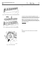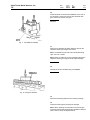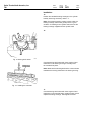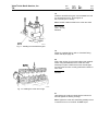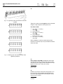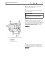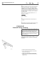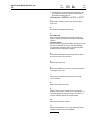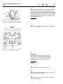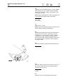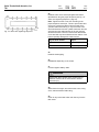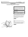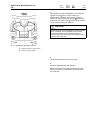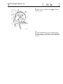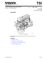
1
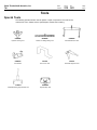
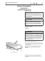
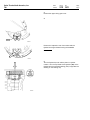
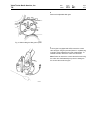
TSI
Volvo Trucks North America, Inc.
Greensboro, NC USA
This TSI Service Bulletin replaces TSI Service Bulletin
215–001, “Camshaft, D12, D12A, D12B” (11.2001),
publication no. PV776–TSP160576.
Date
Group
No.
8.2003
215 001
Supp.
Page
1(21)
Camshaft
D12, D12A, D12B
Camshaft
W2002653
Fig. 1: VOLVO D12B Engine
This information covers procedures for camshaft repair on VOLVO D12, D12A, and
D12B engines.
Contents
• “Special Tools” page 2
• “Camshaft Timing, Checking” page 12
• “Camshaft Timing, Check and Adjust” page 18
• “Camshaft, Replacement” page 3
PV776-TSP193344
USA13899
Volvo Trucks North America, Inc.
TSI
Date
Group
No.
Page
8.2003
215
001
2(21)
Tools
Special Tools
The following special tools are used to replace or repair components. The tools can be
ordered from Volvo. Please use the specified part number when ordering.
9996956
9998255
9998264
Flywheel Turning Tool
Rocker Arm Bridge Lifting Tool
Camshaft Removal Tool
9998270
J-41272
J-42773
Counterhold
Front Cover Tool
Camshaft Alignment Tool
J-44457
9996950
Camshaft Bearing Cap Removal Tool
Flywheel Stop Tool
Volvo Trucks North America, Inc.
TSI
Date
Group
No.
Page
8.2003
215
001
3(21)
Service Procedures
2154-03-02-01
Camshaft, Replacement
(With EPG or VEB)
You must read and understand the precautions and
guidelines in Service Information, Group 20, "General
Safety Practices, Engine" before performing this
procedure. If you are not properly trained and certified
in this procedure, ask your supervisor for training
before you perform it.
CAUTION
Observe the greatest possible cleanliness when
working on the cylinder head. Dirt particles in the
fuel and oil channels can cause the unit injectors to
malfunction, and can cause the VEB (if equipped)
to fail.
Special tools: 9996956, 9998255, 9998264,
9998270, J-44457
Removal
1
WARNING
Use a hoist or get assistance when lifting components
that weigh 23 kg (50 lb.) or more. Make sure all lifting
devices such as chains, hooks, or slings are in good
condition and are of the correct capacity. Make sure
hooks are positioned correctly. Always use a spreader
bar when necessary. The lifting hooks MUST NOT be
side loaded. Failure to follow these warnings may
result in personal injury.
Remove the valve cover (valve cover should be removed
from the exhaust side of the engine).
Note: On WIA, bring the valve cover towards the radiator
to remove. On WG, it is necessary to remove the engine
cover (doghouse).
Note: Be careful that the stud bolts do not loosen.
Otherwise, the unit injector wiring harness can be
damaged.
T2006731
Fig. 2: Valve cover
2
Disconnect the connector for the electrical wires on
the upper timing gear cover. Remove the clamp and
the cover.
Volvo Trucks North America, Inc.
TSI
Date
Group
No.
Page
8.2003
215
001
4(21)
3
Remove the upper timing gear cover.
4
T2006672
Remove the inspection cover from underneath the
flywheel housing and install turning tool 9996956.
9996956
T2008251
5
Turn the flywheel around until the piston in cylinder
number 1 is in the Top Dead Center position (0 ) on the
flywheel and the camshaft marking (TDC) is opposite the
marking on the bearing cap.
T2008250
Volvo Trucks North America, Inc.
TSI
Date
Group
No.
Page
8.2003
215
001
5(21)
6
Remove the adjustable idler gear.
T2007095
Fig. 3: Bolts holding the idler gear in place
7
If the engine is equipped with VEB, remove the control
valve and pipe. Plug the ports and place it in a plastic bag
to avoid it being subjected to dirt and contamination. To
facilitate removal, remove the valve cover stud bolt.
Note: Failure to remove the control valve before removing
the rocker arm shaft assembly may result in damage to
the control valve and/or the pipe.
T2008812
Volvo Trucks North America, Inc.
TSI
Date
Group
No.
Page
8.2003
215
001
6(21)
8
T2006777
Fig. 4: Removing the rocker arm shaft assembly bolts
Loosen the rocker arm shaft bolts gradually to avoid
bending the arm shaft assembly. Remove the bolts, install
tool 9998255 and lift off the rocker arm shaft assembly.
Note: On engines equipped with VEB, wrap a rubber
band around each exhaust rocker lever and slave piston.
This is to prevent the VEB slave pistons from falling out of
their rocker arm bore.
9998255
W2000937
Fig. 5: Removing the rocker arm shaft assembly
9
Remove the cam sensor wheel from the camshaft
drive gear.
T2007096
Fig. 6: Cam sensor wheel
Volvo Trucks North America, Inc.
TSI
Date
Group
No.
Page
8.2003
215
001
7(21)
10
Install camshaft counterhold tool 9998270 on the rear of
the camshaft. Loosen and remove the camshaft drive
gear center bolt and the cam gear.
9998270
T2007148
Fig. 7: Tool 9998270 installed
11
Remove the camshaft cap bolts. Mark the caps for the
respective bearing housings, and remove.
Note: To facilitate the removal of the camshaft bearing
caps, use tool J–44457.
Note: Failure to match the correct camshaft cap with the
respective bearing housing will cause engine damage.
J–44457
12
Carefully lift off the camshaft using tool 9998264.
9998264
C2000508
Fig. 8: Lifting the camshaft
13
Remove the bearing shells from the bearing housings.
14
Inspect the bearings and housings for damage.
Note: When replacing the camshaft on the D12 engine,
remember that the bearing shells are available in different
sizes. Refer to Group 20, Specifications.
Volvo Trucks North America, Inc.
TSI
Date
Group
No.
Page
8.2003
215
001
8(21)
Installation
15
Position the camshaft bearing housings on the cylinder
head by observing the factory marks 1–7.
Note: Check that the mating surface is clean under the
bearing housings and that the guide pins are in good
condition. If installing a new cylinder head, also use the
bearing housings supplied with the cylinder head.
16
T2007126
Fig. 9: Bearing shell halves
Coat the bearing shell halves with clean engine oil and
install them in the bearing housings. Carefully lower
the camshaft into place.
Note: Make sure that bearing shells of the correct size are
installed and correctly positioned in the bearing housing.
C2000508
Fig. 10: Installing the camshaft
17
Coat the bearing shell halves with clean engine oil and
install them in the camshaft caps. Install the caps on their
respective bearing housings. Hand-tighten the bolts.
Volvo Trucks North America, Inc.
TSI
Date
Group
No.
Page
8.2003
215
001
9(21)
18
Install the camshaft drive gear. Use tool 9998270 to lock
the camshaft into place. Torque-tighten to
645 ± 25 Nm (475 ± 18 ft-lb).
Note: Do NOT install the bolts for the rocker arm shaft.
645 ± 25 Nm
(475 ± 18 ft-lb)
9998270
T2007148
Fig. 11: Installing the camshaft drive gear
19
Adjust the camshaft timing; refer to “Camshaft Timing,
Check and Adjust” page 18.
20
Apply clean engine oil to the valve bridges and camshaft
lobes. Using tool 9998255, lift the rocker arm shaft
assembly into place. Make sure that the valve bridges
and the rocker arms are correctly positioned in relation to
each other.
9998255
T2006820
Fig. 12: Installing the rocker arm bridge
21
Hand-tighten the rocker arm shaft with the bolts until it
bottoms against the bearing housings.
Note: Tighten the rocker arm shaft bolts gradually so that
no distortions occur on the shaft. Do NOT torque.
Volvo Trucks North America, Inc.
TSI
Date
Group
No.
8.2003
215
001
Page
10(21)
22
T2006777
Fig. 13: Tightening rocker arm shaft and camshaft
together
Tighten the rocker arm shaft together with the camshaft,
using the 5-step sequence and torques shown:
D12, D12A, D12B:
1
2
3
4
5
15 ± 5 Nm (11 ± 4 ft-lb);
+90 ± 5
45 Nm (33 ft-lb)
15 ± 5 Nm (11 ± 4 ft-lb);
+90 ± 5
45 Nm (33 ft-lb);
loosen to 0 Nm (0 ft-lb)
15 ± 5 Nm (11 ± 4 ft-lb);
+90 ± 5
When reinstalling a rocker arm shaft that has been
loosened or removed, torque only the bolts that hold the
rocker arm shaft.
W2003520
Fig. 14: Bearing caps and camshaft/rocker shaft,
tightening sequence
23
Note: (Engines with VEB:) Reinstall the VEB control
valve Reconnect sliding valve and pipe into the rocker
arm shaft as a unit. Apply Loctite to threads and torque
tighten the bolts to 33 ± 4 Nm (24 ± 3 ft-lb).
33 ± 4 Nm
(24 ± 3 ft-lb)
24
Install the cam sensor wheel and mounting bolts. Turn
the cam sensor wheel clockwise (as viewed from the
front of the engine) against the mounting bolts; torque
bolts to 25 Nm (19 ft-lb).
25 Nm
(19 ft-lb)
Volvo Trucks North America, Inc.
TSI
Date
Group
No.
8.2003
215
001
Page
11(21)
25
Clean the contact surfaces for the upper timing gear
cover. Install a new rubber seal.
26
Apply an even bead of sealant around the timing gear
cover. Install the cover.
CAUTION
Do not allow sealant to harden before installing the
cover. The bolts must be torque-tightened within
20 minutes.
27
Install the alignment tool J–41272 on the forward
right-hand valve cover stud using an existing valve cover
nut. To attach the left-hand side, thread the bolt (supplied
with the tool) into the hole in the cylinder head. The top
of the cover must be flush with the top of the cylinder
head. Otherwise, oil leaks may result.
J–41272
W2002163
Fig. 15: Installing alignment tool J–41272
1
2
3
4
Upper gear cover
Alignment tool
Valve cover nut
Bolt supplied with J–41272
28
Draw the cover down evenly until the cylinder head and
cover are aligned. Tighten cover mounting bolts in the
proper sequence and torque to 33 ± 3 Nm (24 ± 3 ft-lb).
33 ± 3 Nm
(24 ± 3 ft-lb)
Volvo Trucks North America, Inc.
TSI
Date
Group
No.
8.2003
215
001
Page
12(21)
29
Rotate the camshaft until the cam sensor wheel tooth
aligns with the cam sensor. Verify that the air gap
is between 0.3 – 0.7 mm (0.012 – 0.028 in.). Adjust if
needed by removing or adding shims between the
sensor and the cover. Relocate the timing cover, before
the sealant hardens, if necessary to aid in obtaining
the proper air gap.
Note: Make sure the air gap is between 0.3 – 0.7
mm (0.011 – 0.028 in.).
0.3 – 0.7 mm
(0.012 – 0.028 in.)
30
Connect the electrical cable to the cam sensor on
the cover.
31
After installing the camshaft, adjust the valves and unit
injectors; refer to Service Information, Group 21.
2154-06-03-01
Camshaft Timing, Checking
(See also “Camshaft Timing, Check and Adjust” page 18.)
You must read and understand the precautions and
guidelines in Service Information, Group 20, "General
Safety Practices, Engine" before performing this
procedure. If you are not properly trained and certified
in this procedure, ask your supervisor for training
before you perform it.
Note: Before using the cam gear timing tool J-42773,
always make sure that the pointer is straight. To check
the straightness (refer to numbers in accompanying
illustration):
W0002186
•
•
Hold the tool with the pointer horizontal (1).
•
If light can be seen between the straight edge
and the pointer, bend the pointer and recheck for
straightness (3).
Place a straight edge 90 degrees to the pointer
along its entire length (2).
Volvo Trucks North America, Inc.
TSI
•
Date
Group
No.
8.2003
215
001
Page
13(21)
Use the portion of the pointer that is fastened to the
tool shaft as a reference surface since this part is
protected from being bent (4).
Special tools: 9996956, J–41272, J–42773
1
Steam clean around the valve cover and the upper
front cover.
2
Disconnect the negative battery lead.
3
VN model only
Drain coolant and then remove the top right fan ring
support and the top radiator neck from the thermostat
housing.
All other models
Remove the fan ring support bracket, remove the fan belt
and then remove the fan, the fan hub and bracket as
one assembly. Relocate in the fan shroud area while
making sure not to damage the radiator.
4
Remove the intake pipe that spans from the air filter to
the turbo and then cover the turbo.
5
Remove the valve cover.
6
Remove the VEB and cam sensor harness connections
to the upper front cover.
7
Disconnect the internal wiring harness to the VEB
control solenoid.
8
Remove the upper front cover.
9
Slightly loosen the cam sensor wheel and note the
position of the wheel in relation to its mounting bolts, i.e.
clockwise against the mounting bolts, in the center, or
counter-clockwise against the mounting bolts.
10
Remove the cam sensor wheel.
11
Remove the inspection cover on the flywheel housing.
Install the engine turning tool 9996956.
9996956
Volvo Trucks North America, Inc.
TSI
Date
Group
No.
8.2003
215
001
Page
14(21)
12
Install camshaft alignment tool J–42773 by inserting the
guide pin into the hole under the camshaft drive gear.
Rotate the tool to position the lever against the drive gear
teeth to ensure that the tool is positioned correctly. Rotate
engine in the direction of rotation until the 2 dots on the
camshaft gear are equally spaced on both sides of the
camshaft alignment tool.
J–42773
T2012262
Fig. 16: Installing camshaft alignment tool
13
Assure that the 0
mark aligns with the flywheel pointer.
W2004266
Fig. 17: Flywheel direction of rotation
14
Re-assemble
Install the cam sensor wheel and mounting
bolts. Turn the cam sensor wheel clockwise (as
viewed from the front of the engine) against
the mounting bolts; torque bolts to 25 Nm
(19 ft-lb).
25 Nm
(19 ft-lb)
15
Clean all sealant from the upper front cover.
16
Apply a bead of silicone sealant around the upper cover
along with a new rubber gasket.
17
Position the upper front cover and install the mounting
bolts; hand tighten only.
Volvo Trucks North America, Inc.
TSI
Date
Group
No.
8.2003
215
001
Page
15(21)
18
Install the front cover positioning tool, J–41272. Tighten
bolts to align front cover. Torque the cover mounting
bolts to 33 ± 4 Nm (24 ± 3 ft-lb). Verify that the cover
is flush with the head.
Note: Tighten positioning tool, J-41272 until upper front
cover is flush with cylinder head on both sides.
J–41272
33 ± 4 Nm
(24 ± 3 ft-lb)
19
Remove tool, J–41272.
Note: Remove any sealant that gets on the cam sensor
wheel to prevent any sensor signal faults.
20
Rotate the camshaft until the cam sensor wheel tooth
aligns with the cam sensor. Verify that the air gap
is between 0.3 – 0.7 mm (0.012 – 0.028 in.). Adjust if
needed by removing or adding shims between the
sensor and the cover. Relocate the timing cover, before
the sealant hardens, if necessary to aid in obtaining
the proper air gap.
21
Remove the engine turning tool and reinstall the cover.
9996956
T2006672
22
Install the VEB solenoid harness and torque nuts to 1.4
Nm (1 ft-lb). Fasten all clips. Connect the external
harness to the front cover.
1.4 Nm
(1 ft-lb)
23
Clean the valve cover and gasket contact surface.
Volvo Trucks North America, Inc.
TSI
Date
Group
No.
8.2003
215
001
Page
16(21)
24
Install the valve cover and torque-tighten the bolts to
specifications using the proper sequence (see Fig. 18:
Valve cover tightening sequence, page 16).
T2007003
Fig. 18: Valve cover tightening sequence
Note: Tighten the valve cover nuts according to the
proper sequence and torque. This is to prevent the valve
cover from cracking and also to keep the studs in the
cylinder head from loosening. If any of the valve cover
stud bolts loosened from the cylinder head when the nuts
were removed, the cable harness for the unit injectors
should be checked. There is a risk that the cable holder
on the stud bolt may have followed with the rotation of the
bolt and possibly damaged the cable harness.
Engine Serial Number
Torque
Below 25748
20 ± 2 Nm (15 ± 1 ft-lb)
Above 25748
30 ± 3 Nm (22 ± 2 ft-lb)
25
Install the intake piping.
26
Reassemble depending on the model.
27
Connect negative battery cable.
WARNING
Always wear safety glasses when working around
batteries. Failure to do so could result in serious
personal injury.
28
Steam clean the engine, around the valve cover, timing
cover, and transmission bellhousing.
29
Check for any active fault codes and clear any inactive
fault codes.
Volvo Trucks North America, Inc.
TSI
Date
Group
No.
8.2003
215
001
Page
17(21)
30
Run the engine until the coolant reaches operating
temperature. Allow to idle for approximately 10 minutes
for cylinder balancing. For cylinder balancing to take
place, the following conditions must be satisfied:
•
•
•
•
•
•
•
•
Idling speed must be below 650 RPM.
•
No fault codes present.
Fuel requirement must be below a specific rating.
Idling adjustment function must not be active.
Constant engine speed mode (PTO) not active.
Cruise control mode not active.
Accelerator pedal in idling position (0%).
Coolant temperature must be above 50
C (122
F).
Vehicle must be at a standstill (vehicle speed sensor
value of 0).
31
Check for leaks.
Volvo Trucks North America, Inc.
TSI
Date
Group
No.
8.2003
215
001
Page
18(21)
2154-06-03-02
Camshaft Timing, Check and Adjust
You must read and understand the precautions and
guidelines in Service Information, Group 20, "General
Safety Practices, Engine" before performing this
procedure. If you are not properly trained and certified
in this procedure, ask your supervisor for training
before you perform it.
CAUTION
Failure to properly set the camshaft timing to the
crankshaft may result in loss of performance, poor fuel
economy, or in extreme cases, engine damage.
Special tools: 9996956, J–41272, J–42773
1
Install the camshaft alignment tool J–42773 by inserting
the guide pin into the hole under the camshaft drive
gear. Rotate the tool to position the lever against the
drive gear teeth to ensure correct positioning of the
camshaft alignment tool.
J–42773
2
Position the camshaft using the flywheel turning tool
9996956.
Note: The camshaft setting must be exactly as illustrated
in the figure. It is important that the camshaft gear
marking is positioned precisely on both sides of the tool in
a line extending from the center of the camshaft.
9996956
T2012262
Volvo Trucks North America, Inc.
TSI
Date
Group
No.
8.2003
215
001
Page
19(21)
3
Using flywheel turning tool 9996956, turn the flywheel
opposite to the direction of engine rotation (A)
approximately 15 BTDC. Then turn the flywheel in
direction of engine rotation (B) until the 0 mark on the
flywheel lines up exactly with the pointer on the flywheel
housing without passing the 0 mark.
CAUTION
If the flywheel is turned past 0 TDC, repeat the above
step, completely. Do not just back up the flywheel.
Turning the flywheel in the opposite direction of
normal rotation will result in an incorrect setting due to
improper gear train lash.
W2003738
Fig. 19: Rotating the flywheel to 0
A
B
TDC
Opposite direction of engine rotation
Direction of engine rotation
4
Clean all sealant from the front of the head.
5
Install the adjustable idler gear assembly.
Note: The bolts are the single-use “stretch” type and
should not be reused. Pipe sealant should be used on
the center bolt.
Volvo Trucks North America, Inc.
TSI
Date
Group
No.
8.2003
215
001
Page
20(21)
6
W2002245
Insert two 0.10 mm (0.004 in.) feeler gauges on the load
sides of the (A and B) gear.
T2008255
7
Torque the bolts to an initial torque of 5 ± 3 Nm (11 ±
2 ft-lb).
Note: An additional 120 ± 5
backlash is confirmed.
is required after the correct
15 ± 3 Nm
(11 ± 2 ft-lb)
8
Check that both feeler gauges have the same
resistance when inserting them and pulling them
out. The correct backlash is 0.05 - 0.17 mm
(0.002 - 0.007 in.).
Volvo Trucks North America, Inc.
TSI
Date
Group
No.
8.2003
215
001
9
Tighten the bolts an additional 120 ± 5
sequence shown.
Page
21(21)
per the torque
W2002245
10
Re-check camshaft timing; refer to “Camshaft Timing,
Checking” page 12. For information on valve adjustment
and injector installation, also refer to Service Information,
Group 21.