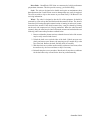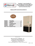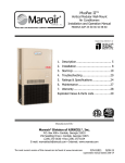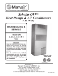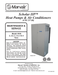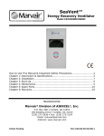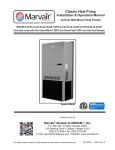
1
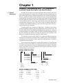
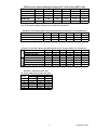
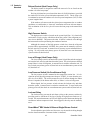
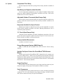
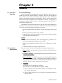
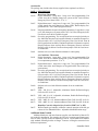
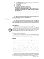
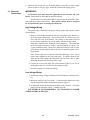
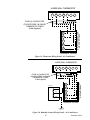
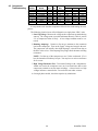
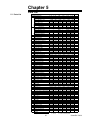
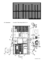
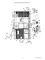
Product
Manual
GreenPac™ and GreenPac HGR™
Vertical Wall Mount
Heat Pumps and Air Conditioners
Description & Specifications...................... 5
Installation ............................................... 21
Start-Up ................................................... 29
Troubleshooting....................................... 31
Parts Lists & Drawings ............................ 35
Maintenance ............................................ 38
Warranty .................................................. 40
Manufactured By:
Marvair™ Division of AIRXCEL®, Inc.
P.O. Box 400 • Cordele, Georgia 31010
156 Seedling Drive • Cordele, Georgia 31015
(229) 273-3636 • Fax (229) 273-5154
E-mail: [email protected] • Internet: www.marvair.com
Part # 01283 7/03-2
supersedes 10/01-1
How to Use
This Manual
This manual is intended to be a comprehensive guide to Marvair’s GreenPac™ &
GreenPac HGR™ line of vertical packaged air conditioners and heat pumps. It contains installation, troubleshooting, maintenance, warranty, and application information. The information contained in this manual is to be used by the installer as a
guide only. This manual does not supercede or circumvent any applicable national
or local codes.
If you are installing the GreenPac™ or GreenPac HGR™ air conditioner or heat
pump, first read Chapter 1 and scan the entire manual before beginning the installation as described in Chapter 2. Chapter 1 contains general, descriptive information
and provides an overview which can speed up the installation process and simplify
troubleshooting.
If a malfunction occurs, follow this troubleshooting sequence:
1. Make sure you understand how the unit works (Chapters 1 & 3).
2. Identify and correct installation errors (Chapter 2).
3. Refer to the troubleshooting information in Chapter 4.
4. Identify defective part(s) (Chapter 5).
If you are still unable to correct the problem, contact the Factory for additional assistance.
Please read the following “Important Safety Precautions” before beginning any
work.
Important
Safety
Precautions
1. USE CARE when LIFTING or TRANSPORTING equipment.
2. TRANSPORT the UNIT UPRIGHT. Laying it down on its side may cause oil to
leave the compressor, resulting in DAMAGE upon START-UP.
3. TURN ELECTRICAL POWER OFF AT THE breaker or fuse box BEFORE
installing or working on the equipment. LINE VOLTAGES ARE HAZARDOUS or LETHAL.
4. OBSERVE and COMPLY with ALL applicable PLUMBING, ELECTRICAL,
and BUILDING CODES & ordinances.
5. SERVICE may be performed ONLY by QUALIFIED and EXPERIENCED PERSONS.
* Wear safety goggles when servicing the refrigeration circuit
* Beware of hot surfaces on refrigerant circuit components
* Beware of sharp edges on sheet metal components
* Use care when recovering or adding refrigerant
Specifications subject to change without notice.
©Marvair™ 7/03
2
GreenPac 7/03-2
Contents
GreenPac™ & GreenPac HGR™ Air Conditioners and Heat
Pumps Description & Specifications
1.1
1.2
1.3
1.4
1.5
1.6
General Description ........................................................................ 5
Ratings and Specifications .............................................................. 6
General Operation ......................................................................... 13
Electrical Diagrams ....................................................................... 14
Controls - Standard ....................................................................... 19
Controls - Optional ........................................................................... 20
Installation
2.1
2.2
2.3
2.4
2.5
2.6
2.7
Equipment Inspection ..................................................................... 21
Installation Requirements ............................................................... 21
Installation Materials....................................................................... 22
Porting & Duct Work ........................................................................ 24
Bracket Installation ........................................................................... 25
Mounting the Unit ............................................................................. 25
Electrical Connections ...................................................................... 26
Start-Up
3.1
3.2
3.3
3.4
Check-Out of Cooling Cycle ............................................................. 29
Check-Out of Heating Cycle ............................................................ 29
Fresh Air Adjustment ........................................................................ 30
Evaporator Variable Fan Speed Controller ....................................... 30
Troubleshooting
4.1
4.2
4.3
Overview .......................................................................................... 31
Failure Symptoms Guide .................................................................. 32
Compressor Troubleshooting ........................................................... 34
Parts List
5.1
5.2
Parts List .......................................................................................... 34
Drawings .......................................................................................... 35
Periodic Maintenance Requirements
6.1
Scheduled Maintenance ................................................................... 38
Warranty Information
7.1
Standard Product Warranty .............................................................. 40
3
GreenPac 7/03-2
Figures
Figure 1a. GreenPac™ & GreenPac HGR™ Unit Dimensions AVP24-36 ................................................................................ 11
Figure 1b. GreenPac™ & GreenPac HGR™ Unit Dimensions AVP42-60 ................................................................................ 12
Figure 2. Refrigerant Circuit ................................................................... 13
Figure 3a. Typical Electrical Schematic - GreenPac™ A/C ..................... 15
Figure 3b. Typical Electrical Schematic - GreenPac HGR™ A/C ............ 16
Figure 3c. Typical Electrical Schematic - GreenPac™ HP ...................... 17
Figure 3d. Typical Electrical Schematic - GreenPac HGR™ HP ............. 18
Figure 4. Wall Mounting Detail - AVP24-60 ........................................... 25
Figure 5a. Thermostat Wiring Detail - A/C............................................... 27
Figure 5b. Humidity Controller Wiring Detail - A/C .................................. 27
Figure 5c. Thermostat Wiring Detail - HP................................................ 28
Figure 5d. Humidity Controller Wiring Detail - HP ................................... 28
Tables
Table 1
Table 2
Minimum Clearances .............................................................. 22
Voltage Limitations ................................................................. 22
Charts
Model Identification ................................................................... 5
Unit Load Amps - Air Conditioner ............................................. 6
Electrical Characteristics - Air Conditioner ............................... 6
Unit Load Amps - Heat Pump ................................................... 8
Electrical Characteristics - Heat Pump ..................................... 8
CFM @ Various Static Pressures ............................................. 9
Unit Load Amps - Heat Pump w/ “S” Circuit ........................... 10
Filter Size ................................................................................ 10
Ship Weight ............................................................................ 10
4
GreenPac 7/03-2
Chapter 1
GreenPac™ and GreenPac HGR ™ Air Conditioners
and Heat Pumps Description and Specifications
1.1 General
Description
The Marvair™ GreenPac™ and GreenPac HGR™ (Hot Gas Reheat) air conditioners and heat pumps are complete, factory assembled systems designed to provide
total comfort while meeting ventilation requirements. The GreenPac and GreenPac
HGR A/C and HPs are built in cooling capacities of 2 ton to 5 tons (24,000 BTUH to
60,000 BTUH). Optional electric heat is available on all models. The GreenPac and
GreenPac HGR units both have the factory installed Marvair™ GreenWheel® ERV.
The GreenWheel® ERV is a total energy wheel that can recover both sensible and
latent heat with efficiencies of up to 75%. The use of the GreenWheel® ERV allows
compliance with ASHRAE standard 62-1999 ventilation requirements while keeping operating costs to a minimum.
GreenPac HGR™ Air Conditioner or Heat Pump - In addition to the factory
installed GreenWheel® ERV, the GreenPac HGR unit has a Hot Gas Reheat coil. The
GreenPac HGR unit provides additional dehumidification capability by working in
conjunction with the GreenWheel® ERV. The HGR coil permits dehumidification of
the fresh and return air without overcooling the classroom. The operation of the
HGR coil is controlled by humidity controller or BAS control.
The GreenPac™ and GreenPac HGR™ air conditioners and heat pumps are
listed by ETL and tested in accordance with UL Standard 1995, 2nd Ed. Ratings and
specifications are in accordance with the applicable standards of the Air Conditioning and Refrigeration Institute.
These instructions explain the recommended methods for installing the
GreenPac™ and GreenPac HGR™ air conditioners and heat pumps and making the
electrical wiring connections to the unit. All internal wiring is complete. The refrigeration system has been factory charged and sealed. Service ports have been provided for field service if required.
MODEL IDENTIFICATION
AVP •
• •
Nominal Cooling
24 = 24,000 BTUH
30 = 30,000 BTUH
36 = 36,000 BTUH
42 = 42,500 BTUH
48 = 50,000 BTUH
60 = 58,000 BTUH
Air
Source
Vertical
Package
•
• •
Power Supply
A = 208/230V, 1 Ph, 60 Hz
C = 208/230V, 3 Ph, 60 Hz
D = 460V, 3 Ph, 60 Hz
Special Option Code
G = HGR (Hot Gas Reheat)
Configuration
H = GreenWheel® ERV
System Type
AC = Air Conditioner
HP = Heat Pump
Electric Heat
00 (None)
4 kW
5 kW
6 kW
8 kW
9 kW
10 kW
15 kW
SERIAL NUMBER DATE CODE
A = January
B = February
C = March
D = April
E = May
F = June
G = July
H = August
J = September
K = October
L = November
M = December
5
L = 2000
M = 2001
N = 2002
P = 2003
R = 2004
S = 2005
T = 2006
U = 2007
V = 2008
W = 2009
GreenPac 7/03-2
1.2 Ratings &
Specifications
GreenPac™ & GreenPac HGR™ Air Conditioners
Cooling Pe rform a nce Cha rt (BTUH) - Gre e nPa c™ & Gre e nPa c HGR™ Air Conditione rs
OUTDOOR AMBIENT DRY BULB TEMPERATURES
MODEL
75°F
80°F
85°F
90°F
95°F
100°F
105°F
24
25,900
25,600 24,900
24,400
24,000 23,000
22,500
30
33,000
32,300 31,200
30,300
29,400 28,500
28,000
36
38,700
38,200 37,200
36,100
35,600 34,300
33,400
42
46,200
45,600 44,600
43,000
41,500 39,900
37,900
48
51,900
50,700 49,700
48,900
48,000 45,500
42,800
60
61,600
60,200 59,000
58,100
57,000 53,600
50,700
Rated indoor air flow at 80°F DB/67°F WB indoor.
110°F
21,900
27,100
32,400
35,200
40,500
47,900
115°F
21,100
26,200
31,200
33,000
38,600
45,600
Ele ctrica l Cha ra cte ristics - Gre e nPa c™ & Gre e nPa c HGR™ Air Conditione rs
BASIC
COMPRESSOR
OUTDOOR FAN MOTOR
INDOOR FAN MOTOR
MODEL
VOLTS Hz/Ph RLA LRA VOLTS Hz/Ph RPM FLA HP VOLTS Hz/Ph RPM FLA HP
AVP24ACA 208/230 60/1 11.6 60 208/230 60/1 1075 1.5
1/5 208/230 60/1 1075 1.4
1/5
AVP30ACA 208/230 60/1 14.7 73 208/230 60/1 1075 1.8
1/4 208/230 60/1 1100 2.5
1/4
AVP36ACA 208/230 60/1 15.6 78.8 208/230 60/1 1075 1.8
1/4 208/230 60/1 1100 2.5
1/4
AVP42ACA 208/230 60/1 19.2 87 208/230 60/1 825 2.8
1/3 208/230 60/1 1075 3.1
1/2
AVP48ACA 208/230 60/1 21.8 105 208/230 60/1 825 2.8
1/3 208/230 60/1 1075 3.1
1/2
AVP60ACA 208/230 60/1 24.5 135 208/230 60/1 825 2.8
1/6 208/230 60/1 1075 5.2
3/4
AVP24ACC 208/230 60/3 8.7
58 208/230 60/1 1075 1.5
1/5 208/230 60/1 1075 1.4
1/5
AVP30ACC 208/230 60/3 9.3
68 208/230 60/1 1075 1.8
1/4 208/230 60/1 1100 2.5
1/4
AVP36ACC 208/230 60/3 10.9 78 208/230 60/1 1075 1.8
1/4 208/230 60/1 1100 2.5
1/4
AVP42ACC 208/230 60/3 14.1 110 208/230 60/1 825 2.8
1/3 208/230 60/1 1075 3.1
1/2
AVP48ACC 208/230 60/3 14.1 130 208/230 60/1 825 2.8
1/3 208/230 60/1 1075 3.1
1/2
AVP60ACC 208/230 60/3
16 137 208/230 60/1 825 2.8
1/3 208/230 60/1 1075 5.2
3/4
AVP24ACD
460
60/3 3.2
30 208/230 60/1 1075 1.5
1/5 208/230 60/1 1075 1.4
1/5
AVP30ACD
460
60/3
5
36 208/230 60/1 1075 1.8
1/4 208/230 60/1 1100 2.5
1/4
AVP36ACD
460
60/3 5.8
40 208/230 60/1 1075 1.8
1/4 208/230 60/1 1100 2.5
1/4
AVP42ACD
460
60/3
7
32.8 208/230 60/1 825 2.8
1/3 208/230 60/1 1075 3.1
1/2
AVP48ACD
460
60/3 7.1
54 208/230 60/1 825 2.8
1/3 208/230 60/1 1075 3.1
1/2
AVP60ACD
460
60/3 8.4
69 208/230 60/1 825 2.8
1/3 208/230 60/1 1075 5.2
3/4
RLA = Rated Load Am ps LRA = Locked Rotor Am ps FLA = Full Load Am ps RPM = Revolutions Per Minute
GREENW HEEL
VOLTS Hz/Ph RLA
208/230 60/1 2.2
208/230 60/1 2.2
208/230 60/1 2.2
208/230 60/1 2.2
208/230 60/1 2.2
208/230 60/1 2.2
208/230 60/1 2.2
208/230 60/1 2.2
208/230 60/1 2.2
208/230 60/1 2.2
208/230 60/1 2.2
208/230 60/1 2.2
208/230 60/1 2.2
208/230 60/1 2.2
208/230 60/1 2.2
208/230 60/1 2.2
208/230 60/1 2.2
208/230 60/1 2.2
HP = Hors epower
Unit Loa d Am ps - Gre e nPa c™ & Gre e nPa c HGR™ Air Conditione rs
BASIC
AIR COND. LOAD OF RESISTIVE HEATING ELEMENTS ONLY*
TOTAL HEATING AMPS (MAX.)
MODEL
AMPS (MAX.) 04 kW 05 kW 06 kW 08 kW 09 kW 10 kW 15 kW 04 kW 05 kW 06 kW 08 kW 09 kW 10 kW 15 kW
AVP24ACA
16.7
16.67
25
33.33
41.67
20.27
28.6 36.93
45.27
AVP30ACA
21.2
20.83
25
41.67 62.5
25.53 29.7
46.37 67.2
AVP36ACA
22.1
20.83
25
41.67 62.5
25.53 29.7
46.37 67.2
AVP42ACA
27.3
20.83
25
41.67 62.5
26.13 30.3
46.97 67.8
AVP48ACA
29.9
20.83
41.67 62.5
26.13
46.97 67.8
AVP60ACA
35.7
20.83
41.67 62.5
28.23
49.07 69.9
AVP24ACC
13.8
14.43
21.65
18.03
25.25
AVP30ACC
15.8
14.43
21.65
36.08
19.13
26.35
40.78
AVP36ACC
17.4
14.43
21.65
36.08
19.13
26.35
40.78
AVP42ACC
22.2
14.43
21.65
36.08
19.73
26.95
41.38
AVP48ACC
22.2
21.65
36.08
26.95
41.38
AVP60ACC
27.2
21.65
36.08
29.05
43.48
AVP24ACD
8.3
7.22
10.83
10.82
14.43
AVP30ACD
11.5
7.22
10.83
18.04
11.92
15.53
22.74
AVP36ACD
12.3
7.22
10.83
18.04
11.92
15.53
22.74
AVP42ACD
15.1
7.22
10.83
18.04
12.52
16.13
23.34
AVP48ACD
15.2
10.83
18.04
16.13
23.34
AVP60ACD
19.6
10.83
18.04
18.23
25.44
* In Am ps
Heating kW shown for 240V for all HPA and HPC models. Derate by 25% for 208V service. Total heating amps for all HPA (208/230V 1ø)
units with 8 kW and larger includes both circuits (#1 and #2). Heating kW shown for 480 for all HPD models. NOTE: Three phase
equipment (HPC and HPD models) contain single-phase motor loads. Values shown are maximum phase loads. Loads are not equally
balanced on each phase. Total heating amps includes motor loads.
6
GreenPac 7/03-2
Efficiency and Capacity Ratings for GreenPac™ & GreenPac HGR™ A/Cs
MODEL
AVP24
AVP30
AVP36
AVP42
AVP48
AVP60
24,000
29,400
35,600
41,500
48,000
57,000
COOLING BTUH
C1
C1
C1
B1
B1
D1
DESIGNATOR
10.1
10.2
10
10.2
10.2
10
SEER
850
1,000
1,220
1,520
1,760
1,850
RATED CFM
0.1
0.15
0.15
0.15
0.2
0.2
ESP
Note: Based upon ARI Standard 210/240 conditions. All performance and capacity ratings are
for a 60 Hz power supply. Ratings are also affected by altitude.
Sensible to Total Ratio @ 95°F Dry Bulb Outside Air for GreenPac™ Air Conditioners
MODEL
24
30
36
42
48
24,000
29,400
35,600
41,500
48,000
TOTAL CAPACITY (BTUH)
0.76
0.78
0.76
0.8
0.8
SENSIBLE HEAT RATIO
18,240
22,930
27,060
33,200
38,400
SENSIBLE CAPACITY (BTUH)
Sensible ratios based on ARI Standard 210/240 Indoor Conditions of 80°F DB/67°F WB.
60
57,000
0.8
45,600
MODEL
HGR
ACTIVE HGR NON-ACTIVE
Se nsible to Tota l Ra tio @ 95°F Dry Bulb Outside Air for Gre e nPa c HGR™ Air Conditione rs
TOTAL CAPACITY (BTUH)
SENSIBLE HEAT RATIO
24
24,000
0.76
30
29,400
0.78
36
35,600
0.76
42
41,500
0.8
48
48,000
0.8
60
57,000
0.8
SENSIBLE CAPACITY (BTUH)
18,240
22,930
27,060
33,200
38,400
45,600
TOTAL CAPACITY (BTUH)
11,400
13,800
16,800
19,600
22,600
26,800
0.55
0.565
0.55
0.58
0.58
SENSIBLE HEAT RATIO
6,270
7,800
9,240
11,370
13,110
SENSIBLE CAPACITY (BTUH)
5,130
6,000
7,560
8,230
9,490
LATENT CAPACITY
SenSens ible ratios bas ed on ARI Standard 240 Indoor Conditions of 80°F DB/67°F WB.
0.58
15,540
11,260
GreenPac™ & GreenPac HGR™ A/Cs
Air Volume (CFM) at Various Static Pressures
Cubic Feet/Minute
MODEL
.10 IWG
.20 IWG
.30 IWG
24
850
810
670
30
1,100
1,000
920
36
1,310
1,220
1,150
42
–––
1,650
1,520
48
–––
1,900
1,760
60
–––
1,900
1,760
IWG = Inches Water Gauge CFM = Cubic Feet/Minute
7
GreenPac 7/03-2
GreenPac™ & GreenPac HGR™ Heat Pumps
Cooling Pe rform a nce Cha rt (BTUH) - Gre e nPa c™ & Gre e nPa c HGR™ He a t Pum ps
MODEL
24
30
36
42
48
60
R ated indoor
OUTDOOR AMBIENT DRY BULB TEMPERATURES
75°F
80°F
85°F
90°F
95°F
100°F
105°F
27,100
26,500
25,600
24,700
24,000
23,400
21,800
33,500
32,600
31,700
30,800
30,000
28,600
26,200
38,300
37,400
37,000
36,200
35,600
33,900
32,200
45,900
45,400
43,800
43,000
42,500
39,500
37,600
54,900
54,200
53,100
51,800
50,000
47,900
44,900
63,800
63,000
61,300
58,300
56,500
54,800
53,600
air flow at 80°F D B/67°F WB indoor.
110°F
20,700
24,800
30,500
35,700
42,700
51,600
115°F
19,500
23,200
29,100
34,100
40,800
48,500
He a ting Pe rform a nce Cha rt (BTUH) - Gre e nPa c™ & Gre e nPa c HGR™ He at Pum ps
MODEL
24
30
36
42
48
60
Rated indoor
OUTDOOR AMBIENT DRY BULB TEMPERATURES
10°F
20°F
30°F
40°F
47°F
50°F
12,000
14,500
16,700
20,100
23,600
24,500
17,600
20,000
22,000
27,100
30,800
31,100
18,900
22,100
26,000
31,100
36,000
37,000
21,300
24,900
30,100
36,500
42,500
43,300
25,000
29,100
35,800
42,200
49,500
50,200
29,500
33,600
41,000
49,800
57,500
58,600
air flow at 70°F DB indoor.
60°F
26,000
32,000
38,400
45,300
51,500
61,500
70°F
27,600
34,300
39,900
47,500
56,200
63,700
Ele ctrica l Cha ra cte ristics - Gre e nPa c™ & Gre e nPa c HGR™ He a t Pum ps
BASIC
COMPRESSOR
OUTDOOR FAN MOTOR
INDOOR FAN MOTOR
MODEL
VOLTS Hz/Ph RLA LRA VOLTS Hz/Ph RPM FLA HP
VOLTS Hz/Ph RPM FLA HP
AVP24HPA 208/230 60/1 12.8 61 208/230 60/1 1075 1.5
1/5 208/230 60/1 1075 1.4
1/5
AVP30HPA 208/230 60/1 14.8 73 208/230 60/1 1075 1.8
1/4 208/230 60/1 1100 2.5
1/4
AVP36HPA 208/230 60/1 18
87 208/230 60/1 1075 1.8
1/4 208/230 60/1 1100 2.5
1/4
AVP42HPA 208/230 60/1 21.8 105 208/230 60/1 825 2.8
1/3 208/230 60/1 1075 3.1
1/2
AVP48HPA 208/230 60/1 24.4 135 208/230 60/1 825 2.8
1/3 208/230 60/1 1075 3.1
1/2
AVP60HPA 208/230 60/1 28.2 135 208/230 60/1 825 2.8
1/3 208/230 60/1 1075 3.1
1/2
AVP24HPC 208/230 60/3
9
58 208/230 60/1 1075 1.5
1/5 208/230 60/1 1075 1.4
1/5
AVP30HPC 208/230 60/3 9.6
68 208/230 60/1 1075 1.8
1/4 208/230 60/1 1100 2.5
1/4
AVP36HPC 208/230 60/3 13.5 110 208/230 60/1 1075 1.8
1/4 208/230 60/1 1100 2.5
1/4
AVP42HPC 208/230 60/3 14.1 130 208/230 60/1 825 2.8
1/3 208/230 60/1 1075 3.1
1/2
AVP48HPC 208/230 60/3 16
137 208/230 60/1 825 2.8
1/3 208/230 60/1 1075 3.1
1/2
AVP60HPC 208/230 60/3 17.8 150 208/230 60/1 825 2.8
1/3 208/230 60/1 1075 3.1
1/2
AVP24HPD
460
60/3 4.2
30 208/230 60/1 1075 1.5
1/5 208/230 60/1 1075 1.4
1/5
AVP30HPD
460
60/3 5.5
36 208/230 60/1 1075 1.8
1/4 208/230 60/1 1100 2.5
1/4
AVP36HPD
460
60/3 6.4
54 208/230 60/1 1075 1.8
1/4 208/230 60/1 1100 2.5
1/4
AVP42HPD
460
60/3 7.1
64 208/230 60/1 825 2.8
1/3 208/230 60/1 1075 3.1
1/2
AVP48HPD
460
60/3 8.3
69 208/230 60/1 825 2.8
1/3 208/230 60/1 1075 3.1
1/2
AVP60HPD
460
60/3 9.6
75 208/230 60/1 825 2.8
1/3 208/230 60/1 1075 3.1
1/2
RLA = Rated Load Am ps LRA = Locked Rotor Am ps FLA = Full Load Am ps RPM = Revolutions Per Minute
GREENW HEEL
VOLTS Hz/Ph RLA
208/230 60/1 2.2
208/230 60/1 2.2
208/230 60/1 2.2
208/230 60/1 2.2
208/230 60/1 2.2
208/230 60/1 2.2
208/230 60/1 2.2
208/230 60/1 2.2
208/230 60/1 2.2
208/230 60/1 2.2
208/230 60/1 2.2
208/230 60/1 2.2
208/230 60/1 2.2
208/230 60/1 2.2
208/230 60/1 2.2
208/230 60/1 2.2
208/230 60/1 2.2
208/230 60/1 2.2
HP = Hors epower
Unit Loa d Am ps - Gre e nPa c™ & Gre e nPa c HGR™ He a t Pum ps
BASIC
HEAT PUMP LOAD OF RESISTIVE HEATING ELEMENTS ONLY*
TOTAL HEATING AMPS (MAX.)
MODEL
AMPS (MAX.) 04 kW 05 kW 06 kW 08 kW 09 kW 10 kW 15 kW 04 kW 05 kW 06 kW 08 kW 09 kW 10 kW 15 kW
AVP24HPA
17.9
16.7
33.3
34.6
51.2
AVP30HPA
21.3
20.8
41.7 62.5
42.1
63
83.8
AVP36HPA
24.5
20.8
41.7 62.5
45.3
66.2
87
AVP42HPA
29.9
20.8
41.7 62.5
50.7
71.6 71.6
AVP48HPA
32.5
20.8
41.7 62.5
53.3
74.2 74.2
AVP60HPA
36.3
20.8
41.7 62.5
57.1
78
78
AVP24HPC
14.1
14.4
28.5
AVP30HPC
16.1
14.4
21.7
36.1
30.5
37.8
52.2
AVP36HPC
20
14.4
21.7
36.1
34.4
41.7
56.1
AVP42HPC
22.2
14.4
21.7
36.1
36.6
43.9
58.3
AVP48HPC
24.1
21.7
36.1
45.8
60.2
AVP60HPC
25.9
21.7
36.1
47.6
62
AVP24HPD
9.3
7.22
16.5
AVP30HPD
12
7.22
10.8
18
19.2
22.8
30
AVP36HPD
12.9
7.22
10.8
18
20.1
23.7
30.9
AVP42HPD
15.2
7.22
10.8
18
22.4
26
33.2
AVP48HPD
16.4
10.8
18
27.2
34.4
AVP60HPD
17.7
10.8
18
28.5
35.7
*In Am ps
Heating kW shown for 240V for all HPA and HPC models. Derate by 25% for 208V service. Total heating amps for all HPA (208/230V 1ø)
units with 8 kW and larger includes both circuits (#1 and #2). Heating kW shown for 480 for all HPD models. NOTE: Three phase
equipment (HPC and HPD models) contain single-phase motor loads. Values shown are maximum phase loads. Loads are not equally
balanced on each phase. Total heating amps includes motor loads.
8
GreenPac 7/03-2
Efficiency and Capacity Ratings for GreenPac™ & GreenPac HGR™ HPs
MODEL
AVP24
AVP30
AVP36
24,000
30,000
35,600
COOLING BTUH
B1
B1
C1
DESIGNATOR
10
10
10
SEER
23,600
30,800
36,000
HTG HI TEMP BTUH
2.7
2.8
2.7
HTG HI TEMP COP
13,600
18,200
21,000
HTG LO TEMP BTUH
1.9
2
2
HTG LO TEMP COP
6.6
6.7
6.9
HSPF REGION IV
850
1,000
1,200
RATED CFM
0.1
0.15
0.15
ESP
Note: Based upon ARI Standard 210/240 conditions. Ratings
AVP42
AVP48
AVP60
42,500
50,000
56,500
B1
C1
C1
10.2
10.2
10
42,500
49,500
57,500
2.8
2.8
2.8
23,800
28,000
34,000
1.9
1.9
2
6.6
6.7
6.6
1,520
1,760
1,875
0.15
0.2
0.2
are also affected by altitude.
Se nsible to Tota l Ra tio @ 95°F Dry Bulb Outside Air for Gre e nPa c™ He a t Pum ps
MODEL
24
30
36
42
48
24,000
30,000
35,600
42,500
50,000
TOTAL CAPACITY (BTUH)
0.755
0.775
0.76
0.8
0.8
SENSIBLE HEAT RATIO
18,120
23,250
27,060
34,000
40,000
SENSIBLE CAPACITY (BTUH)
Sens ible ratios bas ed on ARI Standard 210/240 Indoor C onditions of 80°F DB/67°F WB.
60
56,500
0.795
44,920
ACTIVE HGR
MODEL
HGR
NON-ACTIVE
Se nsible to Tota l Ra tio @ 95°F Dry Bulb Outside Air for Gre e nPa c HGR™ He a t Pum ps
24
30
36
42
48
60
TOTAL CAPACITY (BTUH)
24,000
30,000
35,600
42,500
50,000
56,500
SENSIBLE HEAT RATIO
0.755
0.775
0.76
0.8
0.8
0.795
SENSIBLE CAPACITY (BTUH)
18,120
23,250
27,060
34,000
40,000
44,920
TOTAL CAPACITY (BTUH)
11,200
14,200
16,800
20,000
23,600
26,600
SENSIBLE HEAT RATIO
0.545
0.56
0.55
0.58
0.58
0.575
SENSIBLE CAPACITY (BTUH)
6,100
7,950
9,240
11,600
13,690
15,300
9,910
11,300
5,100
6,250
7,560
8,400
LATENT CAPACITY (BTUH)
Sens ible ratios bas ed on ARI Standard 240 Indoor Conditions of 80°F DB/67°F WB.
Gre e nPa c™ & Gre e nPa c HGR™ HPs
Air Volum e (CFM) a t Va rious Sta tic Pre ssure s
MODEL
.10 IW G
24
850
30
1,100
36
1,310
42
–––
48
–––
60
–––
IWG = Inches Water Gauge
Cubic Feet/Minute
.20 IW G
.30 IW G
810
670
1,000
920
1,220
1,150
1,650
1,520
1,875
1,760
1,875
1,760
CFM = Cubic Feet/Minute
9
GreenPac 7/03-2
GreenPac™ & GreenPac HGR™ Heat Pumps with “S” Circuit
Unit Load Am ps - Gre enPac™ & Gre enPa c HGR™ He at Pumps - “S” Circuit
BASIC
HEAT PUMP LOAD OF RESISTIVE HEATING ELEMENTS ONLY*
TOTAL HEATING AMPS (MAX.)
MODEL
AMPS (MAX.) 04 kW 05 kW 06 kW 08 kW 09 kW 10 kW 15 kW 04 kW 05 kW 06 kW 08 kW 09 kW 10 kW 15 kW
AVP24HPA
17.9
16.67
33.33
41.67
20.27
36.93
45.27
AVP30HPA
21.3
20.83
41.67 62.5
25.53
46.37 67.2
AVP36HPA
24.5
20.83
41.67 62.5
25.53
46.37 67.2
AVP42HPA
29.9
20.83
33.33
41.67 62.5
26.13
38.63
46.97 67.8
AVP48HPA
32.5
20.83
41.67 62.5
26.13
46.97 67.8
AVP60HPA
36.3
20.83
41.67 62.5
26.13
46.97 67.8
AVP24HPC
14.1
21.65
25.25
AVP30HPC
16.1
21.65
36.08
26.35
40.78
AVP36HPC
20
21.65
36.08
26.35
40.78
AVP42HPC
22.2
21.65
36.08
26.95
41.38
AVP48HPC
24.1
21.65
36.08
26.95
41.38
AVP60HPC
25.9
21.65
36.08
26.95
41.38
AVP24HPD
9.3
10.83
14.43
AVP30HPD
12
10.83
18.04
15.53
22.74
AVP36HPD
12.9
10.83
18.04
15.53
22.74
AVP42HPD
15.2
10.83
18.04
16.13
23.34
AVP48HPD
16.4
10.83
18.04
16.13
23.34
AVP60HPD
17.7
10.83
18.04
16.13
23.34
* In Am ps
*”S” Circuit – Control configuration limits electrical demand by preventing simultaneous operation of the electric heat pump and the electric
heat. Heating kW shown for 240V for all HPA and HPC models. Derate by 25% for 208V service. Total heating amps for all HPA (208/30V
1ø) units with 8 kW and larger includes both circuits (#1 and #2). Heating kW shown for 480 for all HPD models. NOTE: Three phase
equipment (HPC and HPD models) contain single-phase motor loads. Values shown are maximum phase loads. Loads are not equally
balanced on each phase. Total heating amps includes motor loads.
MODEL
24/30/36
42/48/60
MODEL
24/30/36
42/48/60
MODEL
24
30
36
42
48
60
FILTER SIZE
INDOOR RETURN FILTER SIZE
27-1/2” x 13-1/2” x 1”
Filament Spun Glass
29-1/2” x 15-1/2” x 1”
Filament Spun Glass
FRESH AIR FILTER SIZE
14” x 14” x 1”
14” x 14” x 1”
Washable Organic Media
Washable Organic Media
SHIP WEIGHT (LBS.)
Air Conditioners
Heat Pumps
GreenPac™ GreenPac HGR™ GreenPac™ GreenPac HGR™
405
425
430
450
410
430
435
455
410
430
435
455
545
570
575
600
570
595
605
630
585
610
620
645
10
GreenPac 7/03-2
43 9/16
42 1/2
MOUNTING HOLES CTR. TO CTR.
41 1/2
.3/8" SQ (10 PLC’S)
SUPPLY AIR DUCT
28 x 8 (NOMINAL)
ELECTRICAL K.O.’S
3/4 x 1Ó
(4 PLACES)
18
RETURN AIR DUCT
28 x 14 (NOMINAL)
69 15/16
70 11/16
67
53 7/16
50 3/4
51 7/16
34 1/2
AIR
OUTLET
18 1/4
2
1 FLANGE TYP.
DRAINAGE 3/4" I.D.
9 1/2
FRONT VIEW
28
6
BACK VIEW
16 13/16
1 1/4
2 7/16
8
CONTROL BOX
COVER
18
69
9 9/16
14
4 5/16
2 5/16
ELECTRICAL K.O.’S
1/2 x 3/4"
(1 PLACE)
28 7/16
26 3/8
AIR
INLET
17-5/8
17-5/8
3/8
(9 PLC'S)
4-9/16 3-9/16
35-1/4
1-1/16
BOTTOM MTG. BRKT.
W/MTG. HOLE LOCATIONS
R.H. SIDE VIEW
Figure 1a. GreenPac™ and GreenPac HGR™ Air Conditioners and Heat Pumps
Dimensional Data - AVP24-36 (in inches)
11
GreenPac 7/03-2
43-1/2
42-1/8
MOUNTING HOLES CTR. TO CTR.
3/8" SQ (10 PLC'S)
SUPPLY AIR DUCT
30 X 10
30
84-1/2
BREAKER
ACCESS
COVER
78.00
1-1/4
RETURN AIR DUCT
30 X 16
1-3/4
60.00
AIR
OUTLET
42.00
3/4" X 1"
32-3/8
30-3/8
ELECTRICAL K.O.'S
24.00
6.00
3/4" ID DRAIN
1.500 FLANGE WIDTH
BACK VIEW
FRONT VIEW
22-5/8
1-1/8
2.00
10
HEATER
ACCESS
COVER
30
3/4" X 1"
1-5/16
ELECTRICAL
K.O.'S
83-5/16
16
40-9/16
38-9/16
26-1/2
AIR
INLET
3/8" (6 PLC'S)
4-5/8" 2-1/4"
1-1/2"
19-3/4"
19-3/4"
41-1/2"
3/4"I.D.
DRAIN
R.H. SIDE VIEW
.
BOTTOM MTG. BRKT.
W/MTG. HOLE LOCATIONS
Figure 1b. GreenPac™ and GreenPac HGR™ Air Conditioners and Heat Pumps
Dimensional Data - AVP42-60 (in inches)
12
GreenPac 7/03-2
Refrigerant Cycle
Cooling Mode (GreenPac™ & GreenPac HGR™ Units)
The GreenPac™ and GreenPac HGR™ units use R-22 refrigerant in a
conventional vapor-compression refrigeration cycle to transfer heat. In the cooling
mode, a double blower assembly blows indoor air across the evaporator (indoor
coil). Liquid refrigerant passing through the evaporator is boiled into gas by heat
removed from the air. The warmed refrigerant gas enters the compressor where its
temperature and pressure are increased. The hot refrigerant gas condenses to liquid
as heat is transferred to outdoor air blown across the condenser (outdoor coil) by the
condenser fan. Liquid refrigerant is metered into the evaporator through capillary
tubes to repeat the cycle.
Reversing Valve
Heating Mode
Cooling Mode
Distributor &
Capillary
Tubes
Indoor Coil
Outdoor Coil
Distributor &
Capillary
Tubes
Discharge Line
Suction Line
1.3 General
Operation
Check Valve
Compressor
Filter Drier
Figure 2. Refrigerant Circuit
Heating Mode (Heat Pump Models Only)
During heating mode a special reversing valve reverses the flow of refrigerant
through the system exchanging the roles of the condenser and evaporator. Now the
outdoor coil becomes the evaporator and the indoor coil becomes the condenser.
The refrigerant then flows through the outdoor coil, picks up heat and becomes
vaporized. The vapor then enters the compressor where it is compressed to a higher
temperature. Next it is pumped to the indoor coil where the heat will be released into
the room. The compressed refrigerant vapor will condense to its liquid state as it
gives up heat. Finally, liquid flows through the capillary tube into the evaporator
where the cycle will be repeated.
Optional electric strip heat is available for all models.
GreenWheel® ERV Operation
All models of the GreenPac™ and GreenPac HGR™ units have a factory installed
GreenWheel® ERV ventilation assembly. The Marvair™ GreenWheel® ERV is a
total energy (both sensible and latent) wheel that can reduce both construction and
operating cost while ventilating the classroom to ASHRAE 62-1999 requirements.
The use of the GreenWheel® ERV reduces the energy load of the outside air.
Exhausting stale, inside air keeps indoor pollutants and harmful gases to a minimum.
The energy recovery wheel has been tested and certified according to ARI Standard
1060.
How It Works
During the summer, cool dry air from the classroom is exhausted through the
13
GreenPac 7/03-2
GreenWheel® ERV to the outside. As the air passes through the rotating wheel, the
desiccant becomes cooler and drier. Simultaneously, hot humid air is being pulled
across the rotating wheel. The cool, dry desiccant absorbs moisture and heat from
the incoming air. The cooler, drier air is mixed with the return air from the classroom
and distributed throughout the room.
In the winter, warm moist air is exhausted through the GreenWheel® ERV to the
outside. As the air passes through the rotating wheel, the desiccant becomes warmer
and absorbs moisture. Simultaneously, cold dry air is being pulled across the rotating wheel. The cold, dry air absorbs heat and moisture from the desiccant. The
warmed air is mixed with the return air from the classroom and distributed throughout the room.
Quality Components
The GreenWheel® ERV cassette consists of the wheel, two blowers and the drive
motor and belt. The two blowers simultaneously pull fresh air from outside and
exhaust air from the classroom through the rotating wheel. The air streams are separated by an insulated partition so that the incoming fresh air is not mixed with the
exhaust air. Two variable speed blowers ensure that up to 450 CFM of outside air
can be brought into the room and the indoor air is properly exhausted. Variable
speed blowers permit that the desired quantity of outside air is delivered into the
room. An optional independent exhaust air blower control allows positive pressurization of the classroom, i.e., more outside air can be introduced through the
GreenWheel ERV than is exhausted.
Dehumidification Mode - GreenPac HGR™ Heat Pumps and Air
Conditioners
When the GreenPac HGR™ A/C or HP is in the dehumidification mode, the hot
gas reheat (HGR) coil is energized. The cooled, dehumidified air exits the evaporator coil and is blown through the HGR coil. This coil is sized to the sensible capacity
of the unit. The heat in the HGR coil is transferred to the air stream. The use of the
HGR coil allows the indoor humidity of the classroom to be maintained at or below
a humidity set point without over cooling the classroom. These units can not add
humidity to the classroom.
The operation of the HGR coil is controlled by a humidity controller. If the
humidity rises above the set point on the controller and the temperature in the classroom is satisfied, both mechanical cooling and the HGR coil operate to temper the
air and lower the humidity. If the temperature in the classroom rises above the set
point of the thermostat and the unit is operating in the dehumidification mode, the
need for cooling (air conditioners) or heating (heat pumps) will override the humidity controller and the HGR coil is disengaged until the thermostat is satisfied. This
assures the classroom temperature is maintained as first priority and humidity control is second.
1.4 Electrical
Diagrams
The compressor and condenser fan are energized with a contactor controlled by
a 24 VAC pilot signal.
The condenser (outside fan) motor is energized by the same contactor.
The compressor incorporates an internal PTC crankcase heater that functions as
long as primary power is available. The heater drives liquid refrigerant from the
crankcase and prevents loss of lubrication caused be oil dilution. Power must be
applied to the unit for 24 hours before starting the compressor.
The indoor evaporator fan motor is cycled by the blower timed delay relay. See
Figures 3a, 3b, 3c.
14
GreenPac 7/03-2
JUMPER
TRANSFORMER
5
Figure 3a. Typical Electrical Schematic Diagram
GreenPac™ Air Conditioner
15
GreenPac 7/03-2
XFMR
Figure 3b. Typical Electrical Schematic Diagram
GreenPac HGR™ Air Conditioner
16
GreenPac 7/03-2
XFMR
WIRE
NUT
NOTE4
Figure 3c. Typical Electrical Schematic Diagram
GreenPac™ Heat Pump
17
GreenPac 7/03-2
Figure 3d. Typical Electrical Schematic Diagram
GreenPac HGR™ Heat Pump
18
GreenPac 7/03-2
1.5 Controls Standard
Defrost Control (Heat Pumps Only)
The defrost control is designed to control the removal of ice or frost from the
outdoor coil of the heat pumps.
De-icing is initiated at a pre-selected time interval (30/45/90 minutes), provided
the outdoor coil is below a preset initiation temperature (26°F). The de-icing cycle
is terminated as soon as the outdoor coil rises to a preset temperature (56°F) or after
a preset length of time.
If the outdoor coil cannot reach the desired preset temperature due to weather
conditions, or a malfunction, a “time-safe” termination will occur after ten minutes.
This termination of the de-ice cycle will restore the heat pump to the normal heat
cycle.
High Pressure Switch
The high pressure switch is located on the system liquid line. It is electrically
connected to a lock-out relay which shuts down the system if the refrigerant pressure rises to 400 PSIG. This protects the units if airflow is reduced or lost through
the heat transfer surface performing the condenser function.
Although the contacts of the high pressure switch close when the refrigerant
pressure falls to approximately 300 PSIG, the system must be manually reset once
the lock-out relay is activated. A manual reset is necessary to prevent harmful shortcycling. To reset switch, turn primary power off, then back on or turn thermostat
system switch off, then back on.
Loss of Charge (Heat Pumps Only)
The loss of charge switch is located on the system’s liquid line and when tripped,
activates the lock-out relay and shuts down the system. This switch protects the heat
pump if there is a loss of refrigerant. A manual reset is needed to restart the unit. To
reset switch, turn primary power off, then back on or turn thermostat system switch
off, then back on.
Low Pressure Switch (Air Conditioners Only)
The low pressure switch is mounted on the compressor suction line. It is designed to open if the refrigerant pressure drops to 35 PSIG; it resets when the pressure rises to 60 PSIG. The switch protects the unit if airflow through the indoor
blower is impeded, if the blower motor fails, or if there is a loss of refrigerant.
When tripped, the low pressure switch activates the lockout relay and shuts
down the system. A manual reset is needed to restart the unit. To reset switch, turn
primary power off, then back on or turn thermostat system switch off, then back on.
Lock-out Relay
The lock-out relay prevents the unit from cycling on the pressure switches by
providing positive shut-down if the loss of charge or high pressure limits are exceeded. On certain thermostats, an LED will light up on the thermostat during this
condition to indicate compressor fault. Once triggered, the relay must be manually
reset.
GreenWheel® ERV Intake & Exhaust Single Blower Control
Used to adjust the speed of the two blowers to vary the outside air being brought
into the classroom and the classroom air that is exhausted.
19
GreenPac 7/03-2
1.6 Options
Compressor Time Delay
Prevents compressor from short cycling. Field or factory installed. Available on
all units.
Start Relay and Capacitor (Hard Start Kit)
Used on single phase equipment to give the compressor higher starting torque
under low voltage conditions. Field installed. Available on all units. (Not recommended for use on scroll compressor.)
Adjustable Outdoor Thermostat (Heat Pumps Only)
Will not allow electric resistance heat to be energized unless the outdoor temperature is below the desired set point. Field or factory installed. Available on all
heat pumps.
Evaporator Variable Fan Speed Control
Manual speed control of indoor blower motor provides adjustable air volume.
Field or factory installed. Available on all units. (Warning: Minimum air flow is
required for proper operation.)
“S” Circuit (Heat Pumps Only)
Limits the electric demand by preventing simultaneous operation of the compressor and electric strip heat; requires only one field power circuit in most cases.
Factory installed. Available on all heat pump units.
Factory Installed Disconnects
Available for all 460V, 3ø units.
Energy Management System (EMS) Relay Kit
Relay to control the unit. Available in 24, 120 or 240 VAC. Field or factory
installed.
Variable Fan Speed Control for GreenWheel® ERV Exhaust
Blower
Variable speed control of GreenWheel® ERV exhaust blower for separate control of the exhaust blower. When used, the standard speed controller control the
intake blower and the optional, second controller operates the exhaust blower. Individual blower control allows positive pressurization of the classroom. Field installed,
P/N S/03335. Can be factory installed.
Single Point Feed
When multiple internal disconnects are used, single point feed permits only one
field power supply to heat pump. Field installed. Available on all units.
Scroll Compressor
All ratings shown on this product data sheet are for the standard reciprocating
compressor. Use of a scroll compressor may change the ratings. Available on most
units. (Please contact the factory for specific information.)
20
GreenPac 7/03-2
Chapter 2
Installation
2.1 Equipment
Inspection
Concealed Damage
Inspect all cartons and packages upon receipt for damage in transit. Remove
cartons and check for concealed damage. Important: Keep the unit upright at all
times. Remove access panels and examine component parts. (Note: The bottom
bracket is stored in the condenser air compartment. Remove it before replacing the
side screen). Inspect refrigerant circuit for fractures or breaks. The presence of
refrigerant oil usually indicates a rupture. If damage is apparent, immediately file a
claim with the freight carrier.
Units that have been turned on their sides or tops may have concealed damage to
compressor motor mounts or to the oil system. If the unit is not upright, immediately
file a claim for concealed damages and follow these steps:
1. Set unit upright and allow to stand for 24 hours with primary power turned
on.
2. Attempt to start the compressor after 24 hours.
3. If the compressor will not start, makes excessive noise, or will not operate,
return the unit to the freight carrier.
General
1. Inspect unit for completeness. Check for missing parts (e.g. hardware). Refer to the installation kit information in section 2.3.
2. Remove access panels and check for loose wires. Tighten screw connections.
3. Complete and mail the warranty registration card.
2.2 Installation
Requirements
You must consider all of the following when choosing the installation site:
1. Noise. Install the unit so that the least amount of noise will be transmitted to
inhabited spaces.
2. Condensate Drainage. Condensate produced during operation must be discharged to a suitable drain.
3. Defrost Drainage. Ice build up sometime occurs during the heating cycle
while in heat pump operation. The automatic reversal (defrost control) of
the heat pump cycle causes the ice to melt so that the heat pump may operate
efficiently. Please keep this in mind while locating unit.
4. Placement.
A) Place the unit in a shaded area, if possible.
B) Install it above ground for protection against flooding.
C) The unit exhausts air. Be sure that the airflow is not impeded by shrubbery or other obstructions.
D) When installing multiple units, please note the recommended clearances
noted in Table 1.
21
GreenPac 7/03-2
5. Airflow Requirements. Note the minimum CFM requirements (section 2.2).
Keep duct lengths as short as possible. Do not obstruct airflow through the
unit.
Applications using duct work should be designed and installed in accordance
with all applicable safety codes and standards. Marvair™ strongly
recommends referring to the current edition National Fire Protection
Association Standards 90A and 90B before designing and installing duct
work. The duct system must be engineered to insure sufficient air flow through
the unit to prevent over-heating of the heater element. This includes proper
supply duct sizing, sufficient quantity of supply registers, and adequate return
and filter areas. Duct work must be of correct material and must be properly
insulated. The duct must be constructed of galvanized steel with a minimum
thickness of .019 inches. Duct work must be firmly attached, secured, and
sealed to prevent air leakage. See section 2.4 for additional duct work
requirements.
6. Clearances. Note the minimum clearances required for proper operation
and service. (See table 1 below).
Table 1. Minimum Clearances
Model Minimum Clearance Minimum Clearance Minimum Space
Around Sides
Between Sides
Above Unit
(Single Unit)
(Two Units)
20/24
30 inches
18 inches
24 inches
30/36
30 inches
18 inches
24 inches
42/48/60
30 inches
30 inches
24 inches
7. Codes. Make sure your installation conforms to all applicable electrical,
plumbing, building, and municipal codes. Some codes may limit installation to single story structures.
8. Electrical Supply. The power supply must have the appropriate voltage,
phase, and ampacity for the model selected. Voltage must be maintained
above minimum specified values listed below. Refer to the Electric Heat
Ratings (section 1.2) for ampacity requirements.
Table 2. Voltage Limitations
Electrical Rating Designations*
A
C
D
208/230
208/230
460
1
3
3
Minimum Voltage
197
187
414
Maximum Voltage
253
253
506
Nominal Voltage
Phase
* Letters refer to model number code designations. Refer to page 3.
2.3 Installation
Materials
Installation Kits
The GreenPac™ and GreenPac HGR™ air conditioners and heat pumps are
shipped with brackets for mounting the unit. All models have built-in side flanges
that function as side brackets. All models require and are shipped with a bottom
mounting bracket. There is also an air intake hood packed inside each unit.
Standard Kit Components
1. One 12 Ga. “L”-shaped bottom bracket
22
GreenPac 7/03-2
Accessories
The package may include other factory-supplied items (optional) as follows:
PART # DESCRIPTION
50122
50107
50116
50100
50101
50121
50123
50100
50109
80675
80676
80672
80673
50057
Heat Pump Thermostats
Digital thermostat. 2 stage heat, 2 stage cool. Non-programmable. Fan
switch: Auto & On. Manual changeover system switch: Cool-Off-HeatEmergency Heat. Status LED’s. °F or °C.
Digital thermostat. 2 stage heat, 2 stage cool. 7 day programmable. Fan
switch: Auto & On. Auto-change over. Status LED’s. Backlit display. Programmable fan. Non-volatile program memory.
Nonprogrammable electronic heat pump thermostat, 2 stage heat, 1 stage
cool. Auto changeover, System switch: Off, Cool, Heat, Emergency heat.
Fan Switch: Auto & On Lockable keypad.
Seven day programming. Two occupied and two unoccupied periods per
day. Individual heat and cool setpoints. Manual or automatic changeover.
System switch: Off, Cool, Heat, Emergency Heat. Fan Switch: Auto &
On. Keypad lockout available. Ventilation terminals. No batteries required.
Display indicates when Auxilary Heat or Emergency Heat are activated.
Requires a 50101 subbase if used on a heat pump or a 50109 if used on an
air conditioner.
Subbase to be used with 50100 thermostat for a heat pump.
Air Conditioner Thermostats
Digital thermostat. 1 stage heat, 1 stage cool. Non-programmable. Fan
switch: Auto & On. Manual changeover system switch: Cool-Off-Heat.
Low temperature protection. °F or °C.
Digital thermostat. 1 stage heat, 1 stage cool. 7 day programmable. Fan
switch: Auto & On. Auto-change over. Keypad lockout. Non-volatile program memory.
Seven day programming. Two occupied and two unoccupied periods per
day. Individual heat and cool setpoints. Manual or automatic changeover.
System switch: Off, Cool, Heat, Emergency Heat. Fan Switch: Auto &
On. Keypad lockout available. Ventilation terminals. No batteries required.
Display indicates when Auxilary Heat or Emergency Heat are activated.
Requires a 50101 subbase if used on a heat pump or a 50109 if used on an
air conditioner.
Subbase to be used with 50100 thermostat for an air conditioner.
Grilles
VPG - 30S, 28 x 8" Adjustable, Aluminum, Double Deflection Supply
Grille for AVP 24-30-36
VPG - 40S, 30 x 10" Adjustable, Aluminum, Double Deflection Supply
Grille for AVP 42-48-60
VPG - 30RF, 28 x 14" Aluminum Return Filter Grille for AVP 24-30-36
VPG - 40RF, 30 x 16" Aluminum Return Filter Grille for AVP 42-48-60
Humidity Controller (Required for GreenPac HGR™ A/C or HP)
Wall mounted type humidity controller controls operation of the hot gas
reheat coil for dehumidification. Adjustable dehumidification range.
Additional Items Needed
Additional hardware and miscellaneous supplies (not furnished by Marvair™)
are needed for installation. For example, the list below contains approximate quantities of items typically needed for mounting a unit on a wood frame wall structure
with standard mounting bracket or flanges. Concrete or fiberglass structures have
different requirements.
23
GreenPac 7/03-2
(10)
3/8" mounting bolts for side brackets. The length needed is typically
the wall thickness plus one inch.
(20)
3/8" washers
(10)
3/8" hex nuts
(6)
3/8" x 2-1/2" lag screws for bottom bracket
• Silicone Sealer to seal around cracks and openings
• 7-conductor low voltage multi-colored wire cable (i.e. thermostat wire)
• Appropriate electrical supplies such as conduit, electrical boxes, fittings,
wire connectors, etc.
• High voltage wire, sized to handle the MCA (minimum circuit ampacity)
listed on the data plate and in the Electric Heat Ratings table in section 1.2.
• Over-Current Protection Device sized in accordance with the MFS (maximum fuse size) listed on the unit data plate and in the Electric Heat Ratings
table in section 1.2.
Duct materials usually are also needed in addition to the mounting hardware. To
save time, design the duct work before mounting the unit.
2.4 Porting and
Duct Work
General Information
Note: The following instructions are for general guidance only. Due to the wide
variety of installation possibilities, specific instructions will not be given. When in
doubt, follow standard and accepted installation practices, or contact Marvair™ for
additional assistance.
Wall Openings
Measure the dimensions of the supply and return ports on the unit.
IMPORTANT
Cut the supply opening in the exterior wall for the supply and return. IMPORTANT: All units with electric heat must have one inch clearance on all four
sides of the supply outlet duct flange on the unit. The one inch clearance must
extend on all sides of the supply duct for the first three feet from the unit.
Minimum Airflow Requirements
The duct system must be engineered to assure sufficient air flow through the
units, even under adverse conditions such as dirty filters, etc. Proper engineering
will insure longevity and maximum performance from the unit.
Ducting
Extensions should be cut flush with the inside wall for applications without duct
work.
Applications using duct work should be designed and installed in accordance
with all applicable safety codes and standards. Marvair™ strongly recommends
referring to the current edition of the National Fire Protection Association Standards 90A and 90B before designing and installing duct work. The duct system must
be engineered to insure sufficient air flow through the unit to prevent over-heating of
the heater element. This includes proper supply duct sizing, sufficient quantity of
supply registers, adequate return and filter area. Ductwork must be of correct material and must be properly insulated. The duct must be constructed of galvanized steel
with a minimum thickness of .019 inches. Ductwork must be firmly attached, secured and sealed to prevent air leakage. Do not use duct liner on inside of supply
duct within four feet of the unit.
Galvanized metal duct extensions should be used to simplify connections to
duct work and grilles. Use fabric boots to prevent the transmission of vibration through
the duct system. The fabric must be UL rated (UL-181) to a minimum of 197oF.
24
GreenPac 7/03-2
2.5 Bracket
Installation
1. Remove and discard the 4” x 4” shipping boards attached to the base of the
unit.
2. All models have built-in mounting flanges. See Figure 4.
3. Refer to Figure 4. Attach the bottom support bracket to the wall using appropriate 3/8" diameter hardware.
For example, on wooden structures, use 3/8 x 2-1/2 inch all-thread lag screws.
The screws must penetrate the center of the wall stud. Drill a pilot hole in the stud to
prevent it from splitting.
FOAM SEAL
GRILLE
SUPPLY AIR
DUCT EXTENSIONS (Not Supplied with Unit)
RETURN AIR
GRILLE
BOTTOM BRACKET
Figure 4. GreenPac™ and GreenPac HGR™ A/C and HP
Wall Mounting Detail - AVP24-60
2.6 Mounting The
Unit
1. For wiring into the back of unit, locate the lower of the two knock-outs on the
wall side of the GreenPac™ and GreenPac HGR™ unit. Drill a one inch hole
in the building wall to match this opening. Allow sufficient clearance to run 3/
4" conduit through the hole and to the unit.
2. Apply a bead of silicone sealer on the wall side of the mounting brackets on the
unit. Circle the mounting holes with the silicone bead.
3. Using an appropriate and safe lifting device, set the unit on the bottom
support bracket mounted on the wall. You must stabilize the unit on the bracket
with the lifting device or by some other means - the bracket alone is not sufficient.
4. Make sure that the duct flanges are properly aligned with the wall opening. Adjust
as necessary.
5. Note the holes in each side flange. Using the holes for guides, drill holes through
the wall with a 3/8 inch drill bit. Insert the six 3/8” lag screws through the
flanges and into the studs. Tighten the bolts to secure the unit.
6. Apply a bead of silicone where the flashing and side flanges contact the unit and
the structure wall.
7. On the inside of the structure, wall sleeves may be installed in the supply and
return air openings. The sleeves should be trimmed to fit flush with the inside
wall.
25
GreenPac 7/03-2
8. Check the fit of each sleeve to its mating flange for possible air leaks. Apply
silicone sealer to close any gaps. Install the air return and supply grilles.
2.7 Electrical
Connections
IMPORTANT!
All electrical work must meet the requirements of local codes and ordinances. Work should be done only by qualified persons.
The GreenPac™ and GreenPac HGR™ units incorporate an internal crankcase heater for compressor protection. The crankcase heater must be energized
for at least 24 hours prior to starting the compressor.
High Voltage Wiring
The power supply should have the proper voltage, phase, and ampacity for the
selected model.
1. Refer to electrical data stamped on the unit rating plate and to Section 1.2
for field wiring requirements. The electrical data lists heater sizes, fuse
sizes, and wire sizes for all models. Also shown are the number for field
power circuits required for the various modes with the electric heaters.
Each unit is marked with a “Minimum Circuit Ampacity”. This means that
the field wiring used must be sized to carry that amount of current. Use
Copper Conductors Only. Refer to the National Electrical Code for complete current carrying capacity data on the various insulation grades of wiring materials.
Note: Power supply service must be within allowable range (+10% - 5%) of
rated voltage stamped on the unit rating plate. To operate nominal 230/
208V unit at 208V, change the transformer line tap from 240V to 208V
following the instruction on wiring label in unit.
2. Connect the wires to the input side of the internal breaker (L1 & L2 for
single-phase units; L1, L2, & L3 for three phase models).
3. Install the ground wire on the ground lug.
Low Voltage Wiring
1. Pull the low voltage wiring from the unit to the thermostat / sub-base assembly.
2. Mount the sub-base on a level plane. Connect the thermostat wire to the
unit terminal board and the thermostat as shown in Figure 5.
3. If applicable, attach the thermostat assembly to the sub-base. Check the
stage two heat anticipator setting - it should read 0.40.
THE INTERNAL TRANSFORMER IS NOT DESIGNED TO POWER
OTHER EXTERNAL DEVICES.
26
GreenPac 7/03-2
4 WIRE WALL THERMOSTAT
G
R
W
Y
LOW VOLTAGE SECTION
AIR CONDITIONER
FOUR (4) CONDUCTOR,
COLOR CODED, 18 GAUGE
THERMOSTAT CABLE
(Field Supplied)
G
R
C
W
Y
TERMINAL BOARD
Figure 5a. Thermostat Wiring Detail - Air Conditioners
4 WIRE WALL THERMOSTAT
G
R
W
Y
LOW VOLTAGE SECTION
AIR CONDITIONER
FOUR (4) CONDUCTOR,
COLOR CODED, 18 GAUGE
THERMOSTAT CABLE
(Field Supplied)
G
Humidistat
R
Blue
C
Red
W
Yellow
Y
TERMINAL BOARD
To Pigtail on RGR
Relay in Unit
Figure 5b. Humidity Control Wiring Detail - Air Conditioners
27
GreenPac 7/03-2
O
X
Y
A
H
G
R
E
W2
Thermostat
Field Supplied
HEAT PUMP LOW VOLTAGE SECTION
Seven (7) Conductor, Color Coded
18 Gauge Thermostat Cable
R
Y
A
O
G
W2
C
Figure 5c. Thermostat Wiring Detail - Heat Pumps
O
X
Y
A
G
H
W2
E
R
Thermostat
Field Supplied
Humidistat
R
Blue
Y
A
Red
O
G
Yellow
W2
C
HEAT PUMP LOW VOLTAGE SECTION
Seven (7) Conductor, Color Coded
18 Gauge Thermostat Cable
To Pigtail on RGR
Relay in Unit
Figure 5d. Humidity Control Wiring Detail - Heat Pumps
28
GreenPac 7/03-2
Chapter 3
Start-Up
Important: Be sure that the crankcase heater has been energized for at least 24
hours prior to start-up of the unit. Double check all electrical connections before applying power. Various thermostats can be used to control the heat pump.
The thermostat may have a fan switch with an Automatic and On positions, a
system switch with Heat, Cool, and Off positions, and an emergency heat
position with lights. The Product Data Sheets have detailed description of the
various Marvair thermostats. Since other thermostats or remote control
systems may be used, the following procedures should be viewed as guidelines
for standard thermostats with system and fan switches.
3.1 Check-Out of
Cooling Cycle
Procedure:
1. Set the fan switch to “Auto” and the system switch to “Off”.
2. Move the cooling temperature selection lever on the wall thermostat to a
point higher than the room temperature. Move the heating temperature selection lever to a temperature that is lower than the room temperature.
3. Set the thermostats system switch to “Cool” or “Auto” position. Nothing
should operate at this time.
4. Set the time delay in the control box to three minutes. Note that the time
delay is an option on the GreenPac™ and GreenPac HGR™ A/C or HP and
may not be on your unit.
5. Remove the cover plate from the thermostat to expose the mercury switches.
Slowly lower the thermostat cooling temperature selection lever until the
top mercury bulb switch closes. Once the indoor fan turns on, allow approximately three minutes for the compressor and outdoor fan to start.
For units equipped with the low ambient control, note that the outdoor fan may
not come on immediately, because it is cycled by refrigerant pressures. Some units
have a time delay module which prevents the compressor from restarting immediately after interruption of power. See section 1.6 for details on the operation of the
time delay.
If the unit fails to operate, refer to the troubleshooting information in Chapter 4.
3.2 Check-Out of
Heating Cycle
Procedure (Heat Pumps Only):
1. Place the thermostat system switch to “Auto” or “Heat” and the fan to “Auto”.
2. Raise the heating temperature selection lever to a setting which is higher
than the room temperature. The compressor should cycle on after time delay has cycled.
3. Move the system switch to the “Off” position. All functions should stop.
The Blower Timed Delay Relay (BTR) keeps the blower running for 90 seconds after the unit shuts off.
Procedure (Resistive Elements):
1. Raise the heating temperature selection lever to a setting which is higher
than the ambient temperature. The fan and electric heat should immediately
cycle on.
2. Move the system switch to the “OFF” position. All functions should stop.
29
GreenPac 7/03-2
3.3 Fresh Air
Adjustment
Fresh Air Adjustment
Using best industry standards and practices, measure the fresh air that is being
brought into the classroom. For units with one speed controller (std.), adjust the
speed of the intake and exhaust blowers by inserting a slotted screw driver into the
opening on the controller. The speed controller is located on the lower right side of
the GreenWheel® ERV assembly. Access to the speed controller is through the return
air grille. Measure the intake air again and adjust the speed of the blowers. Repeat as
necessary to meet the fresh air requirements.
For units with the optional variable fan speed controller for the GreenWheel®
ERV exhaust blower, first measure the air being introduced into the classroom using
best industry standards and practices. Adjust the speed of the intake air GreenWheel
ERV blower until the required outside air is being brought into the classroom.
Now measure the exhaust air from the classroom. Adjust the speed of the exhaust
air GreenWheel® ERV blower until the required air is being exhausted from the
classroom. The exhaust air controller is located on the lower left side of the
GreenWheel ERV assembly. Access to the exhaust air controller is through the return
air grille. It is usual practice to pressurize the classroom by exhausting slightly less
air than is being brought into the classroom.
3.4 Evaporator
Variable Fan
Speed
Controller
Evaporator Variable Fan Speed Controller (Optional)
Indoor evaporator fan controller is accessed through the return air opening. The
controller is located on the GreenWheel® ERV assembly on the air separation box in
a 2” x 4” “J” box.
Note: Sufficient airflow is required for proper operation of the unit.
30
GreenPac 7/03-2
Chapter 4
Troubleshooting
4.1 Overview
A comprehensive understanding of the operation of the GreenPac™ and GreenPac
HGR™ air conditioners and heat pumps is a prerequisite to troubleshooting. Please
read the Chapter 1 for basic information about the unit.
Marvair™ GreenPac™ and GreenPac HGR™ units are thoroughly tested
before they are shipped from the factory. Of course, it is possible that a defect may
escape undetected, or damage may have occurred during transportation. However,
the great majority of problems result from installation errors.
If you experience difficulties with the GreenPac™ or GreenPac HGR™ units,
please review the installation steps in Chapter 2.
IMPORTANT
Much time can be saved by taking a thoughtful and orderly approach to troubleshooting. Start with a visual check - are there loose wires, crimped tubing, missing
parts, etc.? Begin deeper analysis only after making this initial inspection.
The troubleshooting information in this manual is basic. The troubleshooting
section contains problem / solution charts for general problems, followed by a compressor section.
Not every problem can be anticipated. If you discover a problem that is not
covered in this manual, we would be very grateful if you would bring it to the attention of our service department for incorporation in future revisions.
As always, please exercise caution and good judgement when servicing the
GreenPac™ or GreenPac HGR™ units. Use only safe and proven service techniques.
Wear safety goggles when servicing the refrigeration circuit.
The refrigerant circuit has hot surfaces, and the electrical voltages inside of the
unit may be hazardous or lethal. SERVICE SHOULD BE PERFORMED ONLY BY
QUALIFIED AND EXPERIENCED PERSONS.
If replacement of a part is required, use only parts provided or purchased from
Marvair™ or authorized by Marvair as a suitable replacement. Use of unauthorized
parts may be hazardous and void the warranty.
31
GreenPac 7/03-2
4.2 Failure
Symptoms
Guide
PROBLEM/SYMPTOM
A. Unit does not run.
NOTE: An internal compressor
time delay will prevent the unit
from starting for .2 to 8 minutes
following start-up.
B. Unit runs for long periods or
continuously; cooling is insufficient.
C. Unit cycles on high pressure
or loss of charge.
LIKELY CAUSE(S)
CORRECTION
1. Power supply problem.
1. Check power supply for adequate phase and voltage.
Check wiring to unit and external breakers or fuses.
2. Tripped internal breaker.
2. Check circuit protection devices
for continuity.
3. Shut off by external thermostat
or thermostat is defective.
3. Check operation of wallmounted thermostat.
4. Unit off on high pressure or loss
of charge.
4. Reset lockout. See section
1.6.
5. Internal component or connection
failure.
5. Check for loose wiring. Check
components for failure.
1. Unit undersized for job.
1. Add additional units for greater
capacity.
2. Low refrigerant.
2. Check for proper charge and
possible refrigerant leak.
3. Component failure.
3. Check internal components,
especially compressor for
proper operation.
4. Dirty filter or reduced airflow.
4. Check air filter(s). Check
blower operation.
Remove
airflow restriction.
1. Loss or restriction of airflow.
1. Check blower assembly for
proper operation. Look for airflow restrictions, e.g., the air filter. Check blower motor and
condenser fan.
2. Restriction in refrigerant circuit.
2. Check for blockage or restriction, especially filter drier and
capillary tube assembly.
3. Refrigerant overcharge (following
field service).
3. Evacuate and recharge to factory specifications.
4. Defective high pressure control
or loss of charge switch.
4. Check limit cut-out pressures. Control is set to
actuate at 35 PSIG (loss of
charge) and 400 PSIG (high
pressure).
32
GreenPac 7/03-2
PROBLEM/SYMPTOM
D. Unit blows fuses or trips
circuit breaker.
E. Water on floor near unit.
F. No space heating or reduced
heating (units equipped with
resistance elements).
LIKELY CAUSE(S)
CORRECTION
1. Inadequate circuit ampacity.
1. Note electrical requirements
in Chapter 2 and correct as
necessary.
2. Short, loose, or improper connection in field wiring.
2. Check field wiring for errors.
3. Internal short circuit. Loose or
improper connection(s) in unit.
3. Check wiring in unit. See wiring and schematic diagrams.
Test components (especially
the compressor) for shorts.
4. Excessively high or low supply
voltage or phase loss (3ø only).
4. Note voltage range limitations
specific to the compressor
troubleshooting section.
1. Obstruction in condensate line.
1. Check for clog or restriction.
2. Obstruction or leak in condensate pan.
2. Check pan for leak or blockage.
3. Unit is not level.
3. Level unit.
1. Defective heating element(s).
1. Check resistance element(s)
for continuity.
2. Thermal limit switch open.
2. Check continuity across thermal limit switch.
3. Defective heater relay.
3. Check relay for proper operation.
4. Open thermal cut-out (TCO).
4. Check across TCO (adjacent
to element(s) for continuity. It
is normally closed.
5. Thermostat set too low.
5. Adjust thermostat.
6. Compressor fault.
6. Reset the lock out relay at
the thermostat.
33
GreenPac 7/03-2
4.3 Compressor
Troubleshooting
MODEL
24
30
36
36 Alt.
42
42 Alt.
48
60
COMPRESSOR
MODEL
H25B
H25B
H25B
AV5533E
H25B
AV5538E
H25A
H25A
RLA
9.6
11.5
14.2
13.5
14.7
15.4
19.0
22.0
LRA
61
73
94
79
87
98
135
135
RUN CAP. COMP. W INDINGS OHMS (1 Ph)
MFD
C-R
C-S
S-R
35
0.957
2.840
3.797
35
0.793
2.720
3.513
45
0.626
1.930
2.556
45
N/A
N/A
N/A
45
0.537
1.060
1.597
45
N/A
N/A
N/A
55
0.356
0.740
1.096
60
0.356
0.740
1.096
It is important to rule out other component failures before condemning the compressor.
The following electrical tests will aid diagnosis on single phase “HPA” units:
1. Start-Up Voltage: Measure the voltage at the compressor terminals during
start-up. The voltage must exceed the minimum shown in Table 8, section
2.2, or compressor failure is likely. A low voltage condition must be corrected.
2. Running Amperage: Connect a clip-on type ammeter to the (common)
lead to the compressor. Turn on the supply voltage and energize the unit.
The compressor will initially draw high amperage; it should soon drop to
the RLA value or less. If the amperage stays high, check the motor winding
resistances.
NOTE: Feel the top of the compressor to see if it has overheated. If it is
hot, the internal overload may be open. You may have to wait several hours
for it to reset.
3. High Voltage/Insulation Test: Test internal leakage with a megohmeter.
Attach one lead to the compressor case on a bare metal tube and to each
compressor terminal to test the motor windings. A short circuit at a high
voltages indicates a motor defect. Do not do this test under vacuum.
4. On single phase models, check the capacitor by substitution.
34
GreenPac 7/03-2
Chapter 5
Parts List
5.1 Parts List
REV. 1
ITEM DESCRIPTION
24
Designators
B1
1 Compressors
HPA - 208/230V, 1 Ph
10060
HPC - 208/230V, 3 Ph
P/10000
HPD - 460V, 3 Ph
10062
2 P.T.C.R. (1PH UNITS only)
3 Compressor Capacitor
50280
Designators
C1
1 Compressors
HPA - 208/230V, 1 Ph
HPC - 208/230V, 3 Ph
HPD - 460V, 3 Ph
3 Compressor Capacitor
4 Compressor Contactor
HPA- (1PH)
50020
HPC,HPD-(3PH)
50040
5 Condenser
60209
6 Outdoor Motor Capacitor
50350
7 Indoor Motor Capacitor
50350
8 Filter-(Organic Media)
80192
9 Indoor Blower-LH
30060
10 Indoor Blower-RH
30065
11 Indoor Motor (IBM)
40045
12 Orifice-Cooling-("H" only)
20082
13 Distributor-Indoor-("H" only)
20118
14 Evaporator Coil
60207
15 Heating Element
16 TCO (Thermal Cut-Out)
80053
17 Limit Switch
70070
18 Accumulator
70320
19 Control Transformer
50141
20 Blower Time Delay Relay (BTR) 50420
21 Terminal Board (TB)
80825
22 Terminal Block-3P
80800
23 Terminal Block-2P
80812
24 Outdoor Fan Motor
40031
25 Fan Blade
30110
26 Orifice-heating( "H"and"HG")
20103
27 Distributor-Outdoor("H"and"HG") 20119
28 Lockout Relay (LOR)
50214
29 High Pressure Switch
70080
30 Loss of Charge Switch (LPS)
70050
31 Motor Mtg. Bracket (OFM)
80420
32 Motor Mtg. Bracket (IBM)
80427
33 Defrost Control
20173
34 Transformer (460v)
50147
35 Reversing Valve
20135
36 Reversing Valve Solenoid
50225
37 Filter Drier
70388
38 Relays
39 Terminal Lug
80271
40 Circuit Breaker-60 AMP-(HPA)
70178
Circuit Breaker-60 AMP-(HPC)
70183
Circuit Breaker-40 AMP-(HPD)
70299
41
42
43
44
45
46
47
48
49
50
GREENWHEEL® ERV ASSY
Blower/Motor assy
Drive Motor
Energy Recov.Wheel
Pulley
Drive Belt
GREENPAC™ HEAT PUMPS
30
36
42
48
B1
B1
B1
C1
10071
10072
10073
10057
10058
10059
50280
C1
50321
C1
10111
10112
10113
50286
50321
C1
10183*
10185*
10184*
50321*
50020
50040
60380
50350
50350
80192
30050
30055
40055
20094
20117
60385
50020
50040
60380
50350
50350
80192
30050
30055
40055
20093
20117
60385
10035
10036
10037
50286
50322
D1
10188**\
10189**\
10190**
50323
50020
50040
60370
50240
50360
80192
30090
30092
40099
20081
20117
60360
50030
50040
60355
50240
50360
80192
30090
30092
40099
20079
20116
60340
10047
10048
10049
50285
50323
D1
4
10191** * 2, **3
10192** * 2, **3
10193** * 2, **3
50315(2)
50030
50040
60355
50240
50360
80192
30090
30092
40099
20078
20116
60340
80053 80053 80053 80053 80053
70070 70070 70070 70070 70070
70320 70320 70330 70340 70340
50141 50141 50141 50141 50141
50420 50420 50420 50420 50420
80825 80825 80825 80825 80825
80800 80800 80800 80800 80800
80812 80812 80812 80812 80812
40096 40096 40098 40098 40098
30115 30115 30135 30135 30135
20077 20083 20076 20066 20069
20119 20119 20119 20121 20121
50214 50214 50214 50214 50214
70080 70080 70080 70080 70080
70050 70050 70050 70050 70050
80420 80420 80426 80426 80426
80427 80427 80428 80428 80428
20173 20173 20173 20173 20173
50147 P/50007 P/50007 P/50007 P/50007
20135 20135 20135 20135 20135
50225 50225 50225 50225 50225
70388 70388 70388 70388 70388
80271
70178
70183
70299
80271
70178
70183
70299
80271
70178
70183
70299
80271
70178
70183
70299
80271
70178
70183
70299
1
40015 40015 40015 40015 40015 40015
40007 40007 40007 40007 40007 40007
01226 01226 01226 01226 01226 01226
80372 80372 80372 80372 80372 80372
P/80390 P/80390 P/80390 P/80390 P/80390 P/80390
GREENPAC HGR™ A/C & HP (Only)
Reheat Coil
60051 60051 60051 60051 60051
Expansion Valve
20224 20228 20032 20032 20222
Distribuor
20223 20221 20221 20221 20219
Check Valve-5/8"
20029 20029 20029 20029 20029
Valve-3 way Diverting
20257 20257 20257 20257 20257
Solenoid Valve
20028 20028 20028 20028 20028
NOTES
1=Optional
2 = Reed Valve
3 = Scroll
4 = PTCR - Start Capacitor
35
NOTES
60
C1
60051
20226
20227
20029
20257
20028
GreenPac 7/03-2
HEATING ELEMENT CHART
UNITS
ELEMENTS CONTACTOR/RELAYS
KW VOLTS
PART
HEAT
DFR
GW R
0
240
50200 50511
4
240
70141 50020 50200 50511
5
240
70142 50020 50200 50511
6
240
70168 50040 50200 50511
8
240
70144 50030 50200 50511
9
240
70145 50040 50200 50511
10
240
70147 50030 50200 50511
15
240
70149 50040 50200 50511
0
460
6
460
70198
9
460
70196
15
460
70197
* For Relay P/N 50511
5.2 Illustrations
50040
50040
50040
50200
50200
50200
HGR
RBI
50511
50511
50511
50511
50511
50511
50511
50511
RELAYS
RGR
RHR
50511
50810
50511
50810
50511
50810
50511
50810
50511
50810
50511
50810
50511
50810
50511
50810
50511 50511 50511
50511 50511 50511
50511 50511 50511
50511 50511 50511
SOCKET* 50501
50810
50810
50810
50810
50811
GreenPac™ Heat Pump Models 24-36
16
17
15
14
13
12
7
10
32
9
33
39
11
8
ON
ON
ON
ON
OFF
OFF
OFF
OFF
40
44
41
6
42
43
4
41
19
20
38
28
27
3
6
5
8
7
10
9
34
38
4
21
1
30
2
29
26
22 23
38
3
35
36
24
31
25
37
5
1
18
FRONT
36
GreenPac 7/03-2
GreenPac HGR™ Heat Pump Models 24-36
47
46
48
16
17
14
15
45
13
12
7
10
32
9
33
39
11
8
ON
ON
ON
ON
OFF
OFF
OFF
OFF
40
6
44
42
41
43
4
41
19
20
38
28
27
3
6
5
8
7
10
9
34
38
4
21
1
30
2
29
26
22 23
38
3
36
35
24
31
25
5
19
1
FRONT
37
49
50
GreenPac 7/03-2
Chapter 6
Maintenance
6.1 Scheduled
Maintenance
Marvair™ strongly recommends that the air conditioner be serviced a minimum
of twice a year – once prior to the heating season and once prior to the cooling
season. At this time the filters, evaporator coil, condenser coil, the cabinet, and
condensate drains should be serviced as described below. Also at this time, the unit
should be operated in the cooling and heating cycles as described in Chapter 3, StartUp. In addition to this seasonal check-out, the GreenPac™ & GreenPac HGR™
units should be maintained as follows:
Air Filter
Inspect the filters monthly. Clean the fresh air filters and replace the return air
filter whenever they are visibly dirty.
Evaporator
If the evaporator becomes clogged or dirty, it may be cleaned by careful vacuuming or with a commercial evaporator cleaning spray. DO NOT use a solvent containing bleach, acetone, or flammable substances. Turn power off before cleaning.
Be careful not to wet any of the electrical components. Be sure the unit has dried
before restarting.
Condenser
Periodically inspect the outdoor condenser coil and the cabinet air reliefs for dirt
or obstructions. Remove foreign objects such as leaves, paper, etc.
If the condenser coil is dirty, it may be washed off with a commercial solvent
intended for this purpose. TURN OFF POWER BEFORE CLEANING! Be sure
that all electrical components are thoroughly dry before restoring power.
Cabinet
The cabinet may be cleaned with a sponge and warm, soapy water or a mild
detergent. Do not use bleach, abrasive chemicals or harmful solvents.
Drains
Regularly check the condensate drain. An obstruction will force water to dump
into the middle of the unit and drain out the sides of the unit, causing discoloration of
the side panels. If discoloration is noted, service the drain.
If a commercial drain solvent is used, flush out the drain pan and system with
plenty of fresh water to prevent corrosion.
GreenWheel® ERV
Bearings - The GreenWheel® ERV is provided with no maintenance inboard
bearings. These ball bearings should require no maintenance during the life of the
equipment.
Drive Motor - The drive motors should require no maintenance. Replacement
motors may be purchased from Marvair™.
38
GreenPac 7/03-2
Drive Belts - GreenWheel® ERV belts are constructed of a high performance
polyurethane elastomer. This belt provides a strong, yet flexible belting.
Seals - The seals are designed to be durable and require no maintenance other
than adjustment, but if seals become worn or damaged they may easily be replaced.
The seals are made to clip on the cassette or post metal easily. Call Marvair™ for
servicing information.
Wheel - The wheel is designed to last the life of the equipment. It should be
protected by a filter to keep dust and dirt from the heat transfer surface. The wheel is
somewhat self cleaning through its normal action of rotating in and out of countercurrent air flow streams. If the wheel becomes dirty, it may be cleaned by blowing
out the unit with compressed air (20 psig maximum). When the wheel becomes
extremely dirty, the wheel may be removed from the cassette and washed with water
following wheel removable procedures outlined below:
1. Remove air handler plenum sections so that the front or back of the cassette
may be easily accessed and cleared.
2. Unbolt the shaft screw on both sides of the shaft. Unbolt one post completely and remove post. Remove the snap ring (on 90° models only) at the
face of the hub. Remove the shaft. Pull the wheel off carefully.
3. With the wheel out, wash the media carefully with water. Once clean, allow
the media to dry out for several hours or days if necessary.
4. Reinstall using the reverse procedure. Run the unit. It may take several hours
for the desiccant to dry out and for the wheel to perform normally.
39
GreenPac 7/03-2
Chapter 7
Warranty
7.1 Limited Product
Warranty
If any part of your Marvair™ Air Conditioner, Heat Pump or Unit Ventilator
fails because of a manufacturing defect within fifteen months from the date of
original shipment from Marvair or within twelve months from the date of original
start-up, whichever is the earlier date, Marvair will furnish without charge,
EXW Cordele, Georgia, the required replacement part. Any transportation,
related service labor, diagnosis calls, filter, driers, and refrigerant are not
included. The owner must provide proof of the date of the original start-up. The
owner’s registration card filed with Marvair, the contractor’s invoice, the
certificate of occupancy or similar document are examples of proof of the date
of the original start-up.
In addition, if the hermetic compressor fails because of a manufacturing
defect within sixty months from the date of original shipment from Marvair™,
Marvair will furnish without charge, EXW Cordele, Georgia, the required
replacement part. Any related service labor, diagnosis calls, filter, driers and
refrigerant are not included. Marvair will pay for non-priority shipping costs of
the compressor during the first twelve months of the warranty period. After the
first twelve months of the warranty period, all costs of shipment and risk of loss
during the shipment of the compressor shall be the responsibility of the owner.
The owner of the product may ship the allegedly defective or malfunctioning product or part to Marvair™, at such owner’s expense, and Marvair will
diagnose the defect and, if the defect is covered under this warranty, Marvair
will honor its warranty and furnish the required replacement part. All costs for
shipment and risk of loss during shipment of the product to Marvair and back
to the owner shall be the responsibility and liability of the owner. Upon written
request by an owner, Marvair may arrange for remote diagnosis of the
allegedly defective or malfunctioning product or part but all costs for transportation, lodging and related expenses with regard to such diagnostic services
shall be the responsibility and liability of the owner.
An owner requesting performance under this Warranty shall provide
reasonable access to the allegedly defective or malfunctioning product or part
to Marvair™ and its authorized agents and employees.
This warranty applies only to products purchased and retained for use
within the U.S.A., Canada, and Mexico. This warranty does not cover damage
caused by improper installation, misuse of equipment or negligent servicing.
THIS WARRANTY CONSTITUTES THE EXCLUSIVE REMEDY OF ANY
PURCHASER OF A MARVAIR™ HEAT PUMP OR AIR CONDITIONER AND
IS IN LIEU OF ALL OTHER WARRANTIES, EXPRESSED OR IMPLIED,
INCLUDING, WITHOUT LIMITATION, ANY IMPLIED WARRANTY OF MERCHANTABILITY OR FITNESS FOR USE, TO THE FULLEST EXTENT
PERMITTED BY LAW. IN NO EVENT SHALL ANY IMPLIED WARRANTY
OF MERCHANTABILITY OR FITNESS FOR USE EXCEED THE TERMS OF
THE APPLICABLE WARRANTY STATED ABOVE AND MARVAIR SHALL
HAVE NO OTHER OBLIGATION OR LIABILITY. IN NO EVENT SHALL
MARVAIR BE LIABLE FOR INCIDENTAL OR CONSEQUENTIAL DAMAGES OR MONETARY DAMAGES.
THIS WARRANTY GIVES YOU SPECIFIC LEGAL RIGHTS, AND YOU
MAY ALSO HAVE OTHER RIGHTS WHICH VARY FROM STATE-TOSTATE. Some states do not allow limitations or exclusions, so the above
limitations and exclusions may not apply to you.
Rev. 902
Supersedes 7/02
40
GreenPac 7/03-2