1
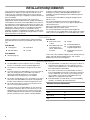
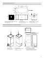
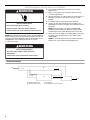
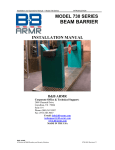
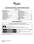
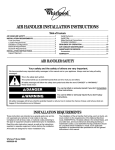
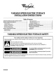
WHOLE HOUSE DEHUMIDIFIER
INSTALLATION INSTRUCTIONS
Table of Contents
WHOLE HOUSE DEHUMIDIFIER SAFETY...................................1
INSTALLATION REQUIREMENTS ................................................2
Tools and Parts ............................................................................2
Location Requirements ................................................................2
Installation Configurations ...........................................................4
Ductwork Requirements ..............................................................5
Electrical Requirements ...............................................................5
INSTALLATION INSTRUCTIONS ..................................................5
Inspect Shipment .........................................................................5
Install Dehumidifier—Existing Furnace or Air Handler.................6
Install Dehumidifier—Existing Furnace or Air Handler
with Fresh Air Duct.......................................................................7
Install Dehumidifier—Existing Furnace or Air Handler
with Dry Air to the Basement or Crawl Space .............................8
Install Dehumidifier—Attic Installation .......................................10
Complete Installation..................................................................11
Make Electrical Connections .....................................................11
SEQUENCE OF OPERATION ......................................................14
Whole House Dehumidifier.........................................................14
WHOLE HOUSE DEHUMIDIFIER MAINTENANCE....................14
Pre-filter ......................................................................................14
HEPA or MERV 11 Air Filter .......................................................14
Fresh Air Return..........................................................................15
UVC Germicidal Light.................................................................15
ASSISTANCE OR SERVICE .........................................................16
WHOLE HOUSE DEHUMIDIFIER SAFETY
Your safety and the safety of others are very important.
We have provided many important safety messages in this manual and on your appliance. Always read and obey all safety
messages.
This is the safety alert symbol.
This symbol alerts you to potential hazards that can kill or hurt you and others.
All safety messages will follow the safety alert symbol and either the word “DANGER” or “WARNING.”
These words mean:
DANGER
WARNING
You can be killed or seriously injured if you don't immediately
follow instructions.
You can be killed or seriously injured if you don't follow
instructions.
All safety messages will tell you what the potential hazard is, tell you how to reduce the chance of injury, and tell you what can
happen if the instructions are not followed.
Whirlpool Gold®Models WGDH160UH and WGDV160UH
Whirlpool® Models WPDH160XS and WPDV160XS
400-1014
INSTALLATION REQUIREMENTS
These instructions are intended as a general guide only for use by
qualified persons and do not supersede any national or local
codes in any way. Compliance with all local, state or national
codes pertaining to this type of equipment should be determined
prior to installation.
Read this entire instruction manual as well as instructions
supplied with separate equipment before starting the installation.
The installation of the whole house dehumidifier must conform to
the requirements of the National Fire Protection Association, the
National Electrical Code, ANSI/NFPA No. 70 (latest edition) in the
United States, and any state laws, local ordinances (including
plumbing or wastewater codes). Local authorities having
jurisdiction should be consulted before installation is made. Such
applicable regulations or requirements take precedence over the
general instructions in this manual.
Install the conditioned air plenum, ducts and air filters (not
provided) in accordance with NFPA 90B Standard for the
Installation of Warm Air Heating and Air-Conditioning Systems
(latest edition).
The whole house dehumidifier is designed and approved for
indoor use only.
It is recommended that the whole house dehumidifier be
matched to the HVAC system to ensure proper operation and
efficient performance.
Refer to the rating plates located on the whole house
dehumidifier and on the HVAC system.
It is recommended that the whole house dehumidifier be
connected to only one existing HVAC system. If there are multiple
HVAC systems in the building, use one dehumidifier per system.
Tools and Parts
Gather the required tools and parts before starting installation.
Read and follow the instructions provided with any tools listed
here.
Parts Needed
Tools Needed
■
Locking pliers
■
Screwdriver
■
Drill and drill bit
■
Tin snips
Parts Supplied
■
Sheet metal screws
or rivets
■
Shop-fabricated sheet
metal turning vanes,
offsets, and transitions,
if needed
■
Sealant
■
Insulated flexible duct
■
³⁄₈"-16 all-thread rod for
suspended applications
■
Insulated duct for fresh air
ventilation
Check local codes and HVAC supplier. Check existing electrical
supply, and read “Electrical Requirements” and “Location
Requirements” before purchasing parts.
■
Grommet plugs (4)
■
The dehumidifier may be installed on all new or existing
furnaces or air handlers used in residential applications.
■
The whole house dehumidifier is designed to be located
indoors.
■
Locate the whole house dehumidifier as close to the return air
duct of an existing furnace or air handler as possible to
minimize the required ductwork for connecting the
dehumidifier to the existing furnace or air handler.
■
The location should allow for access to the filter access panel
at the front of the dehumidifier for inspection and replacing
the filter. See the Minimum Clearance Requirements chart.
■
The location must allow for access to the electrical access
panel for servicing and maintenance.
■
Locate the whole house dehumidifier in an area where the
temperature is between 40ºF (4ºC) and 125ºF (52ºC). If the
dehumidifier is located in an area of extreme heat or high
humidity, additional external insulation may be required to
prevent condensation on the exterior of the dehumidifier.
Location Requirements
2
■
If the dehumidifier is located above a living area or above an
area where water leakage may cause damage (see local
codes for other requirements), a secondary drain pan must
be installed under the dehumidifier.
■
The controls for the whole house dehumidifier are remote
from the dehumidifier and must be located in the space that
is to be conditioned. The controls are low voltage (24-volt)
and should be connected to the dehumidifier with code
approved, low voltage thermostat cable.
■
If the dehumidifier is located directly on structural building
members, use vibration absorbers/eliminators.
Minimum Clearance Requirements
For Optimum Service Access
Front
24"
Rear
12"
Blower End
12"
Top
12"
Horizontal Installation Dimensions
32"
A
A
Top View
16"
22¹⁄₂"
B
22¹⁄₂"
49"
20⁵⁄₈"
C
D
18⁷⁄₈"
I
20⁵⁄₈"
G
H
F
Left-Side View
E
Front View
A. Suspension holes for ³⁄₈"-16 all-thread rod (4)
B. 10" round discharge air outlet
C. Low voltage entry
Right-Side View
D. Line voltage entry
E. ³⁄₄" PVC condensate drain outlet
F. Electrical access panel
G. Internal component access panel
H. Filter access panel
I. Duct flange on return air inlet
Vertical Installation Dimensions—Upflow/Counterflow
21³⁄₁₆"
A
22"
A
Top View
19⁵⁄₈"
24" Minimum
Clearance for Optimum
Service Access
B
B
G
H
56"
C
22¹⁄₄"
E
I
F
A. Return air inlet
B. Filter access panel
C. Low voltage entry
D. Line voltage entry
E. Right-side discharge air outlet
cover
F. Electrical access panel
F
Front View
D
E
Right-Side View
G. Internal component access panel
H. ³⁄₄" PVC condensate drain outlet
I. 10" round discharge air outlet, left side
(shipped right, convertible to left or rear)
3
Installation Configurations
For ease in installation, it is best to make any necessary
configuration changes before setting the dehumidifier in place.
See “Installation Configuration Options” for the specific
installation.
Vertical Installations
Counterflow/Side Discharge
The dehumidifier must be supported on the bottom only and set
on a field-supplied supporting frame with a return air inlet
opening. Securely attach the dehumidifier to the supporting
frame.
Installation Configuration Options
Suspended Cabinet Installation
NOTE: Ensure there is adequate room to remove the dehumidifier
access panels. See Minimum Clearance Requirements chart in
“Location Requirements.”
■ The suspending installation uses field-fabricated ³⁄₈"-16 allthread rod passing through the top panel and connected to
the dehumidifier base.
■
The ³⁄₈"-16 all-thread rod should be attached to the
appropriate lengths of angle iron or equivalent structural steel
which is attached to building structure capable of supporting
the weight of the dehumidifier.
■
If the dehumidifier is not suspended by ³⁄₈"-16 all-thread rod,
use the grommet plugs to cover the holes in the grommets.
Installation Configuration Options
A
B
A
B
C
C
A. Left discharge
B. Right discharge
C. Rear discharge
A. ³⁄₈"-16 all-thread rod
B. Grommet
C. Top panel
Horizontal Installations
Horizontal installations can be only right-hand air supply. The
cabinet must be supported by the building structure to ensure
cabinet integrity. Ensure that there is adequate room to remove
the access panels if installing in the horizontal position. See
Minimum Clearance Requirements in “Location Requirements.”
A
B
Installation Configuration Options
C
A
A. Left to right airflow
A. ³⁄₈"-16 all-thread rod
B. ³⁄₈" threaded hole
C. Dehumidifier base
4
Ductwork Requirements
Electrical Requirements
Install the conditioned air plenum, ducts and air filters (not
provided) in accordance with NFPA 90B Standard for the
Installation of Warm Air Heating and Air-Conditioning Systems
(latest edition).
For the best performance, draw air from the central part of the
building and return it to the outer areas of the building.
Insulated flexible duct may be used on the discharge air supply
side of the dehumidifier to reduce air noise from the fan.
Flexible duct is recommended on all connections to reduce noise
and vibration transmitted to rigid ductwork in the building.
WARNING
Electrical Shock Hazard
Use 12 gauge solid copper wire.
Duct Size
■
■
Electrically ground dehumidifier.
Connect ground wire to green ground lug.
For supply duct lengths up to 25 ft, use a minimum of 10"
diameter round or equivalent rectangular duct. For return
duct lengths up to 25 ft, use a minimum of 12" diameter
round or equivalent rectangular duct.
For supply duct lengths longer than 25 ft, use a minimum of
12" diameter or equivalent rectangular duct. Grilles or
diffusers installed on the duct ends should not restrict airflow.
For return duct lengths longer than 25 ft, use a minimum of
14" diameter round or equivalent rectangular duct.
■
For two or three isolated areas that do not have any heat or
air conditioning ductwork, use a minimum of 8" diameter
branch duct to each area.
■
For four or more isolated areas with stagnant air, use a
minimum of 6" diameter branch duct to each area.
Failure to follow these instructions can result in death,
fire, or electrical shock.
Recommended Grounding Method
■
A 110- to 120-volt, 14.5 FLA amps, 60 Hz, AC only 20-amp
fused, grounded electrical supply is required.
■
All field wiring must be done in accordance with National
Electrical Code requirements, applicable requirements of UL,
or local codes, where applicable.
INSTALLATION INSTRUCTIONS
WARNING
Inspect Shipment
WARNING
Excessive Weight Hazard
Fire Hazard
Read and follow all instructions provided for
installation, service, alteration, or maintenance.
Failure to follow these instructions can result in death
or fire.
Use two or more people to move and install
dehumidifier.
Failure to do so can result in back or other injury.
This whole house dehumidifier is shipped in one package,
completely assembled and wired.
1. Check the dehumidifier rating plate to confirm specifications
are as ordered.
2. Upon receipt of equipment, inspect it for possible shipping
damage. Examine the dehumidifier inside the carton if the
carton is damaged.
If damage is found, it should be noted on the carrier’s freight bill.
Damage claims should be filed with the carrier immediately.
Claims of shortages should be filed with the seller within 5 days.
NOTE: If any damages are discovered and reported to the carrier,
do not install the dehumidifier, because your claim may be
denied.
5
Install Dehumidifier—Existing Furnace or Air Handler
2. Place the dehumidifier in final location. See “Location
Requirements.”
3. Attach ³⁄₄" PVC pipe to the condensate drain outlet. See
“Location Requirements.”
4. Run the PVC pipe to an outdoor drain. Any horizontal run of
drain pipe must have an anti-siphon vent for it to drain
properly.
5. If needed, install a condensate pump kit (optional).
6. Using a 10" duct, attach the discharge air supply on the
dehumidifier to the return air supply on the existing furnace or
air handler.
NOTE: Install ductwork in accordance with NFPA 90B
Standard for the Installation of Warm Air Heating and Air
Conditioning Systems (latest edition) and any local codes.
WARNING
Electrical Shock Hazard
Disconnect power before servicing.
Replace all parts and panels before operating.
Failure to do so can result in death or electrical shock.
7. Attach the return air supply on the dehumidifier to the return
air supply on the existing furnace or air handler near the
return air grille.
NOTE: Do not draw air directly from the kitchen, bathroom,
laundry room or unconditioned isolated basement.
NOTE: When using the existing duct system, the dehumidifier fan
and the existing system fan must be interlocked by using the low
voltage interlock method provided with the dehumidifier. See the
wiring diagrams in the “Electrical Connections” section.
1. Disconnect power.
WARNING
Excessive Weight Hazard
Use two or more people to move and install
dehumidifier.
Failure to do so can result in back or other injury.
Horizontal Installation
B
A
C
D
A. Return air from house
B. Existing return air duct
6
C. Dehumidifier
D. To existing furnace or air handler
Vertical Installation
B
A
C
D
A. Return air from house
B. Existing return air duct
C. Dehumidifier
D. To existing furnace or air handler
Install Dehumidifier—Existing Furnace or Air Handler with Fresh Air Duct
NOTE: Locate the outside air intake away from undesirable
fumes, gases or odors.
Advantages of fresh air ventilation:
■
Outside air is filtered before entering the building.
■
Outside air will be dehumidified by the dehumidifier before
entering the building.
■
Outside air entering the building through the dehumidifier
helps equalize pressure to prevent humid air from entering
the building through other means.
■
In cold climates, outside air can have a lower dew point and
can lower humidity inside the building without running the
dehumidifier.
WARNING
Electrical Shock Hazard
Disconnect power before servicing.
Replace all parts and panels before operating.
Failure to do so can result in death or electrical shock.
NOTE: When using the existing duct system, the dehumidifier fan
and the existing system fan must be interlocked by using the low
voltage interlock method provided with the dehumidifier. See the
wiring diagrams in the “Electrical Connections” section.
1. Disconnect power.
WARNING
Excessive Weight Hazard
Use two or more people to move and install
dehumidifier.
Failure to do so can result in back or other injury.
2. Place the dehumidifier in final location. See “Location
Requirements.”
3. Attach ³⁄₄" PVC pipe to the condensate drain outlet. See
“Location Requirements.”
4. Run the PVC pipe to an outdoor drain. Any horizontal run of
drain pipe must have an anti-siphon vent for it to drain
properly.
5. If needed, install a condensate pump kit (optional).
6. Using a 10" duct, attach the discharge air supply on the
dehumidifier to the return air supply on the existing furnace or
air handler.
NOTE: Install ductwork in accordance with NFPA 90B
Standard for the Installation of Warm Air Heating and Air
Conditioning Systems (latest edition) and any local codes.
7. Attach the return air supply on the dehumidifier to the return
air supply on the existing furnace or air handler near the
return air grille.
NOTE: Do not draw air directly from the kitchen, bathroom,
laundry room or unconditioned isolated basement.
8. Using a 6" diameter insulated duct, attach to the return
plenum on the dehumidifier.
9. Install the outside air intake in a location away from
undesirable fumes, gases and odors.
10. Install a screened intake hood on the outside air intake duct.
Be sure screen is clear of debris at all times to ensure proper
air flow to dehumidifier.
11. Install a manual damper on the return air side of the
dehumidifier.
NOTE: If desired, a power damper may be installed.
7
Horizontal Installation
B
A
D
C
G
E
H
F
A. Return air from house
B. Existing return air duct
C. To existing furnace or air handler
D. Dehumidifier
E. Power damper (optional)
F. Manual damper (required)
G. Outside air
H. Screened intake hood
Vertical Installation
A
H
B
G
E
F
D
C
A. Return air from house
B. Existing return air duct
C. To existing furnace or air handler
D. Dehumidifier
E. Power damper (optional)
F. Manual damper (required)
G. Outside air
H. Screened intake hood
Install Dehumidifier—Existing Furnace or Air Handler with Dry Air to the Basement or Crawl Space
To reduce the humidity that can be found under buildings and in
damp basements, install a supply air duct from the dehumidifier
to the basement or crawl space.
WARNING
NOTE: When using the existing duct system, the dehumidifier fan
and the existing system fan must be interlocked by using the low
voltage interlock method provided with the dehumidifier. See the
wiring diagrams in the “Electrical Connections” section.
1. Disconnect power.
WARNING
Excessive Weight Hazard
Use two or more people to move and install
dehumidifier.
Electrical Shock Hazard
Failure to do so can result in back or other injury.
Disconnect power before servicing.
Replace all parts and panels before operating.
Failure to do so can result in death or electrical shock.
8
2. Place the dehumidifier in final location. See “Location
Requirements.”
3. Attach ³⁄₄" PVC pipe to the condensate drain outlet. See
“Location Requirements.”
4. Run the PVC pipe to an outdoor drain. Any horizontal run of
drain pipe must have an anti-siphon vent for it to drain
properly.
5. If needed, install a condensate pump kit (optional).
6. Using a 10" duct, attach the discharge air supply on the
dehumidifier to the return air supply on the existing furnace or
air handler.
NOTE: Install ductwork in accordance with NFPA 90B
Standard for the Installation of Warm Air Heating and Air
Conditioning Systems (latest edition) and any local codes.
7. Attach the return air supply on the dehumidifier to the return
air supply on the existing furnace or air handler near the
return air grille.
NOTE: Do not draw air directly from the kitchen, bathroom,
laundry room or unconditioned isolated basement.
8. Attach insulated flexible duct to the discharge air supply on
the dehumidifier.
9. Run duct to the basement or crawl space of the building.
Horizontal Installation
B
A
G
C
I
J
D
H
F
F
E
A. Return air from house
B. Existing return air duct
C. To existing furnace or air handler
D. Backflow damper (required)
E. Dry air to crawl space or unconditioned isolated basement
F. Manual damper (required)
G. Dehumidifier
H. Power damper (optional)
I. Outside air
J. Screened intake hood
Horizontal Installation with Added Return
A
B
K
C
J
I
G
H
D
G
E
F
A. Added return
B. Return air from house
C. Existing return air duct
D. To existing furnace or air handler
E. Back flow damper (required)
F. Dry air to crawl space or unconditioned isolated basement
G. Manual damper (required)
H. Dehumidifier
I. Power damper (optional)
J. Outside air
K. Screened intake hood
9
Install Dehumidifier—Attic Installation
WARNING
Electrical Shock Hazard
Disconnect power before servicing.
Replace all parts and panels before operating.
Failure to do so can result in death or electrical shock.
NOTES:
■ Install a secondary drain pan with a drain or float interrupt
under the dehumidifier to prevent damage to ceiling or living
space below.
■
When using the existing duct system, the dehumidifier fan
and the existing system fan must be interlocked by using the
low voltage interlock method provided with the dehumidifier.
See the wiring diagrams in the “Electrical Connections”
section.
1. Disconnect power.
WARNING
Excessive Weight Hazard
Use two or more people to move and install
dehumidifier.
Failure to do so can result in back or other injury.
2. Place the dehumidifier in final location. See “Location
Requirements.”
10
3. Attach ³⁄₄" PVC pipe to the condensate drain outlet. See
“Location Requirements.”
4. Run the PVC pipe to an outdoor drain. Any horizontal run of
drain pipe must have an anti-siphon vent for it to drain
properly.
5. If needed, install a condensate pump kit (optional).
6. Place a secondary drain pan under the dehumidifier.
7. Using a 10" duct, attach the discharge air supply on the
dehumidifier to the return air supply on the existing lower
level furnace or air handler.
NOTE: Install ductwork in accordance with NFPA 90B
Standard for the Installation of Warm Air Heating and Air
Conditioning Systems (latest edition) and any local codes.
8. Attach the return air supply on the dehumidifier to the return
air supply on the existing upper level furnace or air handler
near the return air grille.
NOTE: Do not draw air directly from the kitchen, bathroom,
laundry room or unconditioned isolated basement.
9. If desired, install a fresh air duct. See “Install Dehumidifier—
Existing Furnace or Air Handler with Fresh Air Duct.”
10. If desired, install a supply air duct to the basement or crawl
space. See “Install Dehumidifier—Existing Furnace or Air
Handler with Dry Air to the Basement or Crawl Space.”
Complete Installation
1. If the dehumidifier is installed on an existing system, seal all
joints in the return air system between the discharge air
supply duct and the return air supply duct on the dehumidifier
and the return air duct of the existing system.
2. If fresh air ventilation is used, remove any debris from
screened intake hood.
3. Replace any access doors removed during the installation.
4. Run the furnace or cooling system through one complete
cycle to be sure the system operates as desired.
Make Electrical Connections
WARNING
5. Connect the line voltage wire to the L1 terminal of the
contactor.
6. Connect the neutral wire to the L2 terminal of the contactor.
7. Connect the ground wire to the green ground lug marked
“Ground.”
A
Electrical Shock Hazard
Disconnect power before servicing.
Replace all parts and panels before operating.
Failure to do so can result in death or electrical shock.
1.
2.
3.
4.
Disconnect all power supplies.
Remove the electrical access panel.
Remove the control box cover.
Route the field supply wires to the dehumidifier’s electrical
connection box.
B
C
A. L1 terminal
B. L2 terminal
C. Green ground lug
8. Replace the control box cover.
9. Replace the electrical access panel.
11
Digital Humidistat with Fan Switch Wiring Diagram
DVA Low Voltage Terminal
Dehumidistat Fan Control
V
R
C
H
V
D
G
X
C
R
D
H
G
GT
RF
GF
X
15-minute time delay “On Make”
“X” required on UH models only
Optional
24-Volt
Damper
Furnace/Air Handler Interlock
“G” Terminal on existing thermostat*
“G” Terminal on furnace or air handler*
(24V Hot) “R” Terminal on furnace or air handler
*Remove existing wire between T-stat and furnace or air handler.
Digital Humidistat with Humidifier Control Wiring Diagram
S2000 & S2020 Humidifier
Dehumidistat Fan Control
DVA Low Voltage Terminal
C
G1
R
G2
H
H
R
C
H
V
D
Furnace/Air Handler Interlock
“G” Terminal on furnace or air handler*
(24V Hot) “R” Terminal on furnace or air handler
*Remove existing wire between T-stat and furnace or air handler.
12
D
H
G
Optional
24-Volt
Damper
“G” Terminal on existing thermostat*
R
Field
Supplied
24-Volt
Relay
N.O.
G
GT
GF
RF
Whole House Humidifier Schematic Diagram
D
G
GF
X
R
H
GT
RF
V
115 Volt, 60 Hz, 20 Amp
1 Phase Power Supply
Y
G
BK
BU
BK
Low Voltage Terminal
C
BU
BU
BR
OR
W
BK
R
W
Contactor
Transformer
W
BK
R
R
BK
*Time Delay
Low
Pressure
Switch
Fan Relay
Freeze
Stat
3
1
2
BU
BK
Blower Motor
C
4
High Speed
For UH
6
5
MH
H
Door
Switch
Compressor
Filter
Pressure
Switch
Overload
Compressor
Run Capacitor
C
S
Lamp
Ballast
R
* Optional Component
BK
R
*Start
Assist
UV
Lamp
UH/UV Models Only
13
SEQUENCE OF OPERATION
Whole House Dehumidifier
The whole house dehumidifier is designed to deliver
dehumidified, filtered air to the living space. Ventilation air can
also be delivered in a controlled fashion using the outside air
venting option.
When the relative humidity exceeds the humidistat set point by
approximately 3%, the humidistat will energize the
dehumidification and air circulation components of the
dehumidifier (with 15-minute delay on digital humidistat). If the
dehumidifier is connected and interlocked with an existing
furnace or air handler, the system’s circulation fan will also be
energized. The dehumidifier will continue to operate until the
humidity level is reduced to the set point selected on the
humidistat and then will cycle off. During this cycle, the air
circulated through the dehumidifier will be filtered and
dehumidified. If an outside ventilation air duct has been installed,
fresh air will be filtered and dehumidified and introduced into the
space during this cycle.
Coil Freeze Protection
The dehumidification coil (evaporator) is equipped with a low
temperature freeze thermostat. If the coil temperature is reduced
to the point of ice buildup, the thermostat will turn off the
compressor while allowing the fan to continue running. Once the
coil has returned to normal conditions, the thermostat will allow
the compressor to restart. The prevailing conditions of the return
air, temperature and humidity will determine the length of this
cycle.
Low Pressure Control
If the low-side refrigerant pressure drops to 20 psig, the low
pressure control opens and turns off the compressor. It is an
automatically reset control that will close when the pressure rises
to 50 psig. It may also open if the dehumidifier is installed in a
cool area below 40ºF and then started. Under these conditions,
the dehumidifier will restart within several minutes. Until the
whole house dehumidifier warms up, it may repeat the cycle
several times.
WHOLE HOUSE DEHUMIDIFIER MAINTENANCE
To assure optimum performance from the whole house dehumidifier, the pre-filter should be replaced every three to six months, and the
HEPA air filter every 18 to 30 months.
Pre-filter
The dehumidifier is equipped with a 2" pleated pre-filter.
Operating the dehumidifier with a dirty pre-filter will reduce
dehumidifier capacity and efficiency and may cause the
compressor to cycle off and on unnecessarily. Under normal
operating conditions, the pre-filter should be replaced every
6 months. However, in high particulate concentrations, more
frequent replacements may be necessary. It is recommended
that the pre-filter be inspected regularly for the first 3 to 4 months
to determine the correct replacement intervals.
To replace the pre-filter
3. Slide the panel out and down until it is free from underneath
the top panel.
4. Remove the pre-filter by pulling the pre-filter straight out of
the dehumidifier.
Replacement pre-filters may be purchased from your installation
contractor or ordered from the factory if a local representative is
not available. Do not operate the dehumidifier without the prefilters, or with less effective pre-filters than originally supplied.
The heat exchange coils inside the dehumidifier could become
clogged and require disassembly to clean.
1. Locate the filter access panel on the left-hand side of the
dehumidifier. See “Location Requirements.”
2. Remove the ⁵⁄₁₆" hex screws from the panel marked “Filter
Access.”
HEPA or MERV 11 Air Filter
The UH model is equipped with a high efficiency HEPA air filter.
This filter is rated MERV 20, and is more efficient and traps
smaller allergy-causing particles than standard air filters. Under
normal operating conditions, the HEPA air filter should be
replaced every 18 to 30 months. However, in high particulate
concentrations more frequent replacements may be necessary.
The dehumidifier is equipped with a pressure sensing system that
monitors the HEPA air filter and signals when the filters should be
serviced. The LED indicator light on the digital humidistat will
flash “FL” when the filters require service. If the filters are not
serviced promptly, damage to the dehumidifier may occur. The
filters may be changed prior to signal.
The HEPA air filter should be used in conjunction with the 2" prefilter. It should be installed in the filter enclosure directly to the
14
right, or downstream of the 2" pre-filter. The 2" pre-filter serves to
prolong the life of the HEPA air filter.
The XS model is equipped with a 4" MERV 11 filter and should
also be used with the 2" pre-filter.
To replace the air filter
1. Locate the filter access panel on the left-hand side of the
dehumidifier. See “Location Requirements.”
2. Remove the ⁵⁄₁₆" hex screws from the panel marked “Filter
Access.”
3. Slide the panel out and down until it is free from underneath
the top panel.
4. Remove the HEPA air filter by pulling the air filter straight out
of the dehumidifier.
NOTES:
■ Handle the HEPA air filter gently to prevent damage to the
fabric media.
■
To replace the UVC light bulb
WARNING
The HEPA air filter should not be cleaned. It should be
replaced when it becomes restrictive.
A
Electrical Shock Hazard
Disconnect power before servicing.
Replace all parts and panels before operating.
B
Failure to do so can result in death or electrical shock.
1.
2.
3.
4.
5.
6.
7.
Disconnect power.
Remove the filter access panel.
Remove the electrical access panel.
Remove the internal component access panel.
Remove the connector from the UVC light and sleeve.
Remove the connector sleeve from the UVC bulb.
Remove the UVC bulb.
A. Pre-filter
B. HEPA filter
Fresh Air Return
If your system includes the optional fresh air return, it will have an
outside air intake. Check and clean the hood screen on the
outside air intake seasonally. The intake hood screen must
remain clear of any debris that could restrict airflow into the
dehumidifier.
A
UVC Germicidal Light
WGDH160UH and WGDV160UH models are equipped with UVC
germicidal ultraviolet lights. The bulb for the germicidal ultraviolet
light is rated for at least 9,000 hours (1 year) when used in
accordance with the whole house dehumidifier installation
instructions. The bulb may last longer in some situations, but
annual bulb replacement is recommended since UVC ouput is
typically reduced by about 25 percent at 9,000 hours and drops
off more rapidly afterward.
B
C
CAUTION: UV Light Hazard RG-3. Harmful to bare skin and
eyes. Can cause temporary or permanent loss of vision.
Never look at the lamps while illuminated. This heating/air
conditioning system is equipped with an ultraviolet air
treatment system. To prevent exposure to ultraviolet light,
disconnect power to the ultraviolet air treatment system
before servicing any part of the heating/air conditioning
system.
A. UVC germicidal light bulb
B. Connector sleeve
C. Connector
8. Replace the UVC bulb.
9. Replace the connector sleeve.
10. Replace the connector.
11. Replace the internal component access panel.
12. Replace the filter access panel.
13. Reconnect power.
15
ASSISTANCE OR SERVICE
If you need further assistance, you can write to the below
address with any questions or concerns:
Whirlpool® Home Cooling and Heating
14610 Breakers Drive
Jacksonville, FL 32258
Please include a daytime phone number in your correspondence.
400-1014
© 2007. All rights reserved.
®Registered Trademark/TM Trademark of Whirlpool, U.S.A.,
Manufactured under license by Tradewinds Distributing Company, LLC., Coconut Grove, Florida
8/07
Printed in U.S.A.