1
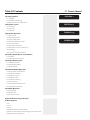
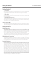
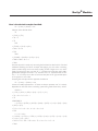
Ci
TM
PROFESSIONAL
POWER AMPLIFIERS
6
6
6
6
6
6
6
6
6
6
6
6
OWNER’S MANUAL
Intended to alert the user to the presence of uninsulated “dangerous voltage” within the product’s
enclosure that may be of sufficient magnitude to constitute a risk of electric shock to persons.
Intended to alert the user of the presence of important operating and maintenance (servicing)
instructions in the literature accompanying the product.
CAUTION: Risk of electrical shock — DO NOT OPEN!
CAUTION: To reduce the risk of electric shock, do not remove cover. No user serviceable parts inside.
Refer servicing to qualified service personnel.
WARNING: To prevent electrical shock or fire hazard, this apparatus should not be exposed to rain or
moisture‚ and objects filled with liquids‚ such as vases‚ should not be placed on this apparatus. Before
using this apparatus‚ read the operating guide for further warnings.
Este símbolo tiene el propósito, de alertar al usuario de la presencia de “(voltaje) peligroso” sin
aislamiento dentro de la caja del producto y que puede tener una magnitud suficiente como para
constituir riesgo de descarga eléctrica.
Este símbolo tiene el propósito de alertar al usario de la presencia de instruccones importantes sobre la
operación y mantenimiento en la información que viene con el producto.
PRECAUCION: Riesgo de descarga eléctrica ¡NO ABRIR!
PRECAUCION: Para disminuír el riesgo de descarga eléctrica, no abra la cubierta. No hay piezas útiles
dentro. Deje todo mantenimiento en manos del personal técnico cualificado.
ADVERTENCIA: Para prevenir choque electrico o riesgo de incendios, este aparato no se debe exponer a
la lluvia o a la humedad. Los objetos llenos de liquidos, como los floreros, no se deben colocar encima
de este aparato. Antes de usar este aparato, lea la guia de funcionamiento para otras advertencias.
Ce symbole est utilisé dans ce manuel pour indiquer à l’utilisateur la présence d’une tension dangereuse
pouvant être d’amplitude suffisante pour constituer un risque de choc électrique.
Ce symbole est utilisé dans ce manuel pour indiquer à l’utilisateur qu’il ou qu’elle trouvera d’importantes
instructions concernant l’utilisation et l’entretien de l’appareil dans le paragraphe signalé.
ATTENTION: Risques de choc électrique — NE PAS OUVRIR!
ATTENTION: Afin de réduire le risque de choc électrique, ne pas enlever le couvercle. Il ne se trouve
à l’intérieur aucune pièce pouvant être reparée par l’utilisateur. Confiez I’entretien et la réparation de
l’appareil à un réparateur Peavey agréé.
AVIS: Dans le but de reduire les risques d’incendie ou de decharge electrique, cet appareil ne doit
pas etre expose a la pluie ou a l’humidite et aucun objet rempli de liquide, tel qu’un vase, ne doit
etre pose sur celui-ci. Avant d’utiliser de cet appareil, lisez attentivement le guide fonctionnant pour
avertissements supplémentaires.
Dieses Symbol soll den Anwender vor unisolierten gefährlichen Spannungen innerhalb des Gehäuses
warnen, die von Ausreichender Stärke sind, um einen elektrischen Schlag verursachen zu können.
Dieses Symbol soll den Benutzer auf wichtige Instruktionen in der Bedienungsanleitung aufmerksam
machen, die Handhabung und Wartung des Produkts betreffen.
VORSICHT: Risiko — Elektrischer Schlag! Nicht öffnen!
VORSICHT: Um das Risiko eines elektrischen Schlages zu vermeiden, nicht die Abdeckung enfernen.
Es befinden sich keine Teile darin, die vom Anwender repariert werden könnten. Reparaturen nur von
qualifiziertem Fachpersonal durchführen lassen.
WARNUNG: Um elektrischen Schlag oder Brandgefahr zu verhindern, sollte dieser Apparat nicht
Regen oder Feuchtigkeit ausgesetzt werden und Gegenstände mit Flüssigkeiten gefuellt, wie Vasen,
nicht auf diesen Apparat gesetzt werden. Bevor dieser Apparat verwendet wird, lesen Sie bitte den
Funktionsführer für weitere Warnungen.
2
IMPORTANT SAFETY INSTRUCTIONS
WARNING: When using electrical products, basic cautions should always be followed, including the following:
1.
2.
3.
4.
5.
6.
7.
8.
9.
10.
11.
12.
13.
14.
15.
16.
17.
18.
19.
Read these instructions.
Keep these instructions.
Heed all warnings.
Follow all instructions.
Do not use this apparatus near water.
Clean only with a dry cloth.
Do not block any of the ventilation openings. Install in accordance with manufacturer’s instructions.
Do not install near any heat sources such as radiators, heat registers, stoves or other apparatus (including amplifiers)
that produce heat.
Do not defeat the safety purpose of the polarized or grounding-type plug. A polarized plug has two blades with one
wider than the other. A grounding type plug has two blades and a third grounding plug. The wide blade or third prong is
provided for your safety. If the provided plug does not fit into your outlet, consult an electrician for replacement of the
obsolete outlet.
Protect the power cord from being walked on or pinched, particularly at plugs, convenience receptacles, and the point
they exit from the apparatus.
Only use attachments/accessories provided by the manufacturer.
Use only with a cart, stand, tripod, bracket, or table specified by the manufacturer, or sold with the apparatus. When a
cart is used, use caution when moving the cart/apparatus combination to avoid injury from tip-over.
Unplug this apparatus during lightning storms or when unused for long periods of time.
Refer all servicing to qualified service personnel. Servicing is required when the apparatus has been damaged in any
way, such as power-supply cord or plug is damaged, liquid has been spilled or objects have fallen into the apparatus,
the apparatus has been exposed to rain or moisture, does not operate normally, or has been dropped.
Never break off the ground pin. Write for our free booklet “Shock Hazard and Grounding.” Connect only to a power
supply of the type marked on the unit adjacent to the power supply cord.
If this product is to be mounted in an equipment rack, rear support should be provided.
Note for UK only: If the colors of the wires in the mains lead of this unit do not correspond with the terminals in your
plug‚ proceed as follows:
a) The wire that is colored green and yellow must be connected to the terminal that is marked by the letter E‚ the earth
symbol‚ colored green or colored green and yellow.
b) The wire that is colored blue must be connected to the terminal that is marked with the letter N or the color black.
c) The wire that is colored brown must be connected to the terminal that is marked with the letter L or the color red.
This electrical apparatus should not be exposed to dripping or splashing and care should be taken not to place objects
containing liquids, such as vases, upon the apparatus.
Exposure to extremely high noise levels may cause a permanent hearing loss. Individuals vary considerably in susceptibility to noise-induced hearing loss, but nearly everyone will lose some hearing if exposed to sufficiently intense noise
for a sufficient time. The U.S. Government’s Occupational Safety and Health Administration (OSHA) has specified the
following permissible noise level exposures:
Duration Per Day In Hours
8
6
4
3
2
1 1⁄2
1
1⁄2
1⁄4 or less
Sound Level dBA, Slow Response
90
92
95
97
100
102
105
110
115
According to OSHA, any exposure in excess of the above permissible limits could result in some hearing loss. Ear plugs or protectors to
the ear canals or over the ears must be worn when operating this amplification system in order to prevent a permanent hearing loss, if
exposure is in excess of the limits as set forth above. To ensure against potentially dangerous exposure to high sound pressure levels, it is
recommended that all persons exposed to equipment capable of producing high sound pressure levels such as this amplification system be
protected by hearing protectors while this unit is in operation.
SAVE THESE INSTRUCTIONS!
WICHTIGE SICHERHEITSHINWEISE
ACHTUNG: Beim Einsatz von Elektrogeräten müssen u.a. grundlegende Vorsichtsmaßnahmen befolgt werden:
1.
Lesen Sie sich diese Anweisungen durch.
2.
Bewahren Sie diese Anweisungen auf.
3.
Beachten Sie alle Warnungen.
4.
Befolgen Sie alle Anweisungen.
5.
Setzen Sie dieses Gerät nicht in der Nähe von Wasser ein.
6.
Reinigen Sie es nur mit einem trockenen Tuch.
7.
Blockieren Sie keine der Lüftungsöffnungen. Führen Sie die Installation gemäß den Anweisungen des Herstellers durch.
8.
Installieren Sie das Gerät nicht neben Wärmequellen wie Heizungen, Heizgeräten, Öfen oder anderen Geräten (auch Verstärkern),
die Wärme erzeugen.
9.
Beeinträchtigen Sie nicht die Sicherheitswirkung des gepolten Steckers bzw. des Erdungssteckers. Ein gepolter Stecker weist
zwei Stifte auf, von denen einer breiter ist als der andere. Ein Erdungsstecker weist zwei Stifte und einen dritten Erdungsstift auf.
Der breite Stift bzw. der dritte Stift dient Ihrer Sicherheit. Sollte der beiliegende Stecker nicht in Ihre Steckdose passen, wenden
Sie sich bitte an einen Elektriker, um die ungeeignete Steckdose austauschen zu lassen.
10.
Schützen Sie das Netzkabel, sodass niemand darauf tritt oder es geknickt wird, insbesondere an Steckern oder Buchsen und
ihren Austrittsstellen aus dem Gerät.
11.
Verwenden Sie nur die vom Hersteller erhältlichen Zubehörgeräte oder Zubehörteile.
12.
Verwenden Sie nur einen Wagen, Stativ, Dreifuß, Träger oder Tisch, der den Angaben des Herstellers entspricht oder zusammen
mit dem Gerät verkauft wurde. Wird ein Wagen verwendet, bewegen Sie den Wagen mit dem darauf befindlichen Gerät besonders
vorsichtig, damit er nicht umkippt und möglicherweise jemand verletzt wird.
13.
Trennen Sie das Gerät während eines Gewitters oder während längerer Zeiträume, in denen es nicht benutzt wird, von der
Stromversorgung.
14.
Lassen Sie sämtliche Wartungsarbeiten von qualifizierten Kundendiensttechnikern durchführen. Eine Wartung ist erforderlich,
wenn das Gerät in irgendeiner Art beschädigt wurde, etwa wenn das Netzkabel oder der Netzstecker beschädigt wurden,
Flüssigkeit oder Gegenstände in das Gerät gelangt sind, das Gerät Regen oder Feuchtigkeit ausgesetzt wurde, nicht normal
arbeitet oder heruntergefallen ist.
15.
Der Erdungsstift darf nie entfernt werden. Auf Wunsch senden wir Ihnen gerne unsere kostenlose Broschüre „Shock Hazard and
Grounding“ (Gefahr durch elektrischen Schlag und Erdung) zu. Schließen Sie nur an die Stromversorgung der Art an, die am
Gerät neben dem Netzkabel angegeben ist.
16.
Wenn dieses Produkt in ein Geräte-Rack eingebaut werden soll, muss eine Versorgung über die Rückseite eingerichtet werden.
17.
Hinweis – Nur für Großbritannien: Sollte die Farbe der Drähte in der Netzleitung dieses Geräts nicht mit den Klemmen in Ihrem
Stecker übereinstimmen, gehen Sie folgendermaßen vor:
a) Der grün-gelbe Draht muss an die mit E (Symbol für Erde) markierte bzw. grüne oder grün-gelbe Klemme angeschlossen
werden.
b) Der blaue Draht muss an die mit N markierte bzw. schwarze Klemme angeschlossen werden.
c) Der braune Draht muss an die mit L markierte bzw. rote Klemme angeschlossen werden.
18.
Dieses Gerät darf nicht ungeschützt Wassertropfen und Wasserspritzern ausgesetzt werden und es muss darauf geachtet
werden, dass keine mit Flüssigkeiten gefüllte Gegenstände, wie z. B. Blumenvasen, auf dem Gerät abgestellt werden.
19.
Belastung durch extrem hohe Lärmpegel kann zu dauerhaftem Gehörverlust führen. Die Anfälligkeit für durch Lärm bedingten
Gehörverlust ist von Mensch zu Mensch verschieden, das Gehör wird jedoch bei jedem in gewissem Maße geschädigt, der über
einen bestimmten Zeitraum ausreichend starkem Lärm ausgesetzt ist. Die US-Arbeitsschutzbehörde (Occupational and Health
Administration, OSHA) hat die folgenden zulässigen Pegel für Lärmbelastung festgelegt:
Dauer pro Tag in Stunden Geräuschpegel dBA, langsame Reaktion
8
6
4
3
2
1 1/2
1
1
/2
1
/4 oder weniger
90
92
95
97
100
102
105
110
115
Laut OSHA kann jede Belastung über den obenstehenden zulässigen Grenzwerten zu einem gewissen Gehörverlust führen. Sollte die Belastung
die obenstehenden Grenzwerte übersteigen, müssen beim Betrieb dieses Verstärkungssystems Ohrenstopfen oder Schutzvorrichtungen
im Gehörgang oder über den Ohren getragen werden, um einen dauerhaften Gehörverlust zu verhindern. Um sich vor einer möglicherweise
gefährlichen Belastung durch hohe Schalldruckpegel zu schützen, wird allen Personen empfohlen, die mit Geräten arbeiten, die wie dieses
Verstärkungssystem hohe Schalldruckpegel erzeugen können, beim Betrieb dieses Geräts einen Gehörschutz zu tragen.
BEWAHREN SIE DIESE SICHERHEITSHINWEISE AUF!
INSTRUCTIONS IMPORTANTES DE SECURITE
ATTENTION: L’utilisation de tout appareil électrique doit être soumise aux precautions d’usage incluant:
1.
2. 3.
4.
5.
6.
7.
8.
9.
10.
11. 12.
13.
14.
15.
16.
17.
18.
19.
Lire ces instructions.
Gardez ce manuel pour de futures références.
Prétez attention aux messages de précautions de ce manuel.
Suivez ces instructions.
N’utilisez pas cette unité proche de plans d’eau.
N’utilisez qu’un tissu sec pour le nettoyage de votre unité.
N’obstruez pas les systèmes de refroidissement de votre unité et installez votre unité en fonction des instructions
de ce manuel.
Ne positionnez pas votre unité à proximité de toute source de chaleur.
Connectez toujours votre unité sur une alimentation munie de prise de terre utilisant le cordon d’alimentation
fourni.
Protégez les connecteurs de votre unité et positionnez les cablages pour éviter toutes déconnexions accidentelles.
N’utilisez que des fixations approuvées par le fabriquant.
Lors de l’utilsation sur pied ou pole de support, assurez dans le cas de déplacement de l’ensemble enceinte/
support de prévenir tout basculement intempestif de celui-ci.
Il est conseillé de déconnecter du secteur votre unité en cas d’orage ou de durée prolongée sans utilisation.
Seul un technicien agréé par le fabriquant est à même de réparer/contrôler votre unité. Celle-ci doit être contrôlée si
elle a subit des dommages de manipulation, d’utilisation ou de stockage (humidité,…).
Ne déconnectez jamais la prise de terre de votre unité.
Si votre unité est destinée a etre montée en rack, des supports arriere doivent etre utilises.
Note pour les Royaumes-Unis: Si les couleurs de connecteurs du cable d’alimentation ne correspond pas au guide
de la prise secteur, procédez comme suit:
a) Le connecteur vert et jaune doit être connectrer au terminal noté E, indiquant la prise de terre ou correspondant
aux couleurs verte ou verte et jaune du guide.
b) Le connecteur Bleu doit être connectrer au terminal noté N, correspondnat à la couleur noire du guide.
c) Le connecteur marron doit être connectrer au terminal noté L, correspondant à la couleur rouge du guide.
Cet équipement électrique ne doit en aucun cas être en contact avec un quelconque liquide et aucun objet
contenant un liquide, vase ou autre ne devrait être posé sur celui-ci.
Une exposition à de hauts niveaux sonores peut conduire à des dommages de l’écoute irréversibles. La susceptibilité au bruit varie considérablement d’un individu à l’autre, mais une large majorité de la population expériencera
une perte de l’écoute après une exposition à une forte puissance sonore pour une durée prolongée. L’organisme de
la santé américaine (OSHA) a produit le guide ci-dessous en rapport à la perte occasionnée:
Durée par Jour (heures)
8
6
4
3
2
1 1/2
1
1
/2
1
/4 ou inférieur
Niveau sonore moyen (dBA)
90
92
95
97
100
102
105
110
115
D’après les études menées par le OSHA, toute exposition au delà des limites décrites ce-dessus entrainera des pertes de l’écoute chez la
plupart des sujets. Le port de système de protection (casque, oreilette de filtrage,…) doit être observé lors de l’opération cette unité ou des
dommages irréversibles peuvent être occasionnés. Le port de ces systèmes doit être observé par toutes personnes susceptibles d’être exposées à des conditions au delà des limites décrites ci-dessus.
GARDEZ CES INSTRUCTIONS!
INSTRUCCIONES IMPORTANTES PARA SU SEGURIDAD
CUIDADO: Cuando use productos electrónicos, debe tomar precauciones básicas, incluyendo las siguientes:
1.
Lea estas instrucciones.
2.
3.
4.
5.
6.
7.
8.
9.
10.
11.
12.
13. 14. 15. 16.
17. 18.
19.
Guarde estas instrucciones.
Haga caso de todos los consejos.
Siga todas las instrucciones.
No usar este aparato cerca del agua.
Limpiar solamente con una tela seca.
No bloquear ninguna de las salidas de ventilación. Instalar de acuerdo a las instrucciones del fabricante.
No instalar cerca de ninguna fuente de calor como radiadores, estufas, hornos u otros aparatos (incluyendo amplificadores)
que produzcan calor.
No retire la patilla protectora del enchufe polarizado o de tipo “a Tierra”. Un enchufe polarizado tiene dos puntas, una de
ellas más ancha que la otra. Un enchufe de tipo “a Tierra” tiene dos puntas y una tercera “a Tierra”. La punta ancha (la
tercera ) se proporciona para su seguridad. Si el enchufe proporcionado no encaja en su enchufe de red, consulte a un
electricista para que reemplaze su enchufe obsoleto.
Proteja el cable de alimentación para que no sea pisado o pinchado, particularmente en los enchufes, huecos, y los puntos
que salen del aparato.
Usar solamente añadidos/accesorios proporcionados por el fabricante.
Usar solamente un carro, pie, trípode, o soporte especificado por el fabricante, o vendido junto al aparato. Cuando se use
un carro, tenga cuidado al mover el conjunto carro/aparato para evitar que se dañe en un vuelco. No suspenda esta caja de
ninguna manera.
Desenchufe este aparato durante tormentas o cuando no sea usado durante largos periodos de tiempo.
Para cualquier reparación, acuda a personal de servicio cualificado. Se requieren reparaciones cuando el aparato ha sido
dañado de alguna manera, como cuando el cable de alimentación o el enchufe se han dañado, algún líquido ha sido
derramado o algún objeto ha caído dentro del aparato, el aparato ha sido expuesto a la lluvia o la humedad, no funciona de
manera normal, o ha sufrido una caída.
Nunca retire la patilla de Tierra.Escríbanos para obtener nuestro folleto gratuito “Shock Hazard and Grounding” (“Peligro
de Electrocución y Toma a Tierra”). Conecte el aparato sólo a una fuente de alimentación del tipo marcado al lado del cable
de alimentación.
Si este producto va a ser enracado con más equipo, use algún tipo de apoyo trasero.
Nota para el Reino Unido solamente: Si los colores de los cables en el enchufe principal de esta unidad no corresponden
con los terminales en su enchufe‚ proceda de la siguiente manera:
a) El cable de color verde y azul debe ser conectado al terminal que está marcado con la letra E‚ el símbolo de Tierra
(earth)‚ coloreado en verde o en verde y amarillo.
b) El cable coloreado en azul debe ser conectado al terminal que está marcado con la letra N o el color negro.
c) El cable coloreado en marrón debe ser conectado al terminal que está marcado con la letra L o el color rojo.
Este aparato eléctrico no debe ser sometido a ningún tipo de goteo o salpicadura y se debe tener cuidado para no poner
objetos que contengan líquidos, como vasos, sobre el aparato.
La exposición a altos niveles de ruido puede causar una pérdida permanente en la audición. La susceptibilidad a la pérdida
de audición provocada por el ruido varía según la persona, pero casi todo el mundo perderá algo de audición si se expone
a un nivel de ruido suficientemante intenso durante un tiempo determinado. El Departamento para la Salud y para la
Seguridad del Gobierno de los Estados Unidos (OSHA) ha especificado las siguientes exposiciones al ruido permisibles:
Duración por Día en Horas
8
6
4
3
2
1 1/2
1
1
/2
1
/4 o menos
Nivel de Sonido dBA, Respuesta Lenta
90
92
95
97
100
102
105
110
115
De acuerdo al OSHA, cualquier exposición que exceda los límites arriba indicados puede producir algún tipo de pérdida en la audición.
Protectores para los canales auditivos o tapones para los oídos deben ser usados cuando se opere con este sistema de sonido para prevenir una pérdida permanente en la audición, si la exposición excede los límites indicados más arriba. Para protegerse de una exposición a
altos niveles de sonido potencialmente peligrosa, se recomienda que todas las personas expuestas a equipamiento capaz de producir altos
niveles de presión sonora, tales como este sistema de amplificación, se encuentren protegidas por protectores auditivos mientras esta unidad esté operando.
GUARDE ESTAS INSTRUCCIONES!
Important Precautions
1
Save the carton and packing material
even if the equipment has arrived in
good condition. Should you ever need
to ship the unit, use only the original
factory packing.
2
Read all documentation before operating your equipment. Retain all documentation for future reference.
3
Follow all instructions printed on unit
chassis for proper operation.
4
5
6
7
8
9
Do not spill water or other liquids into
or on the unit, or operate the unit while
standing in liquid.
Make sure power outlets conform to
the power requirements listed on the
back of the unit.
Do not use the unit if the electrical
power cord is frayed or broken. The
power supply cords should be routed
so that they are not likely to be walked
on or pinched by items placed upon or
against them, paying particular attention
to cords and plugs, convenience receptacles, and the point where they exit
from the appliance.
Always operate the unit with the AC
ground wire connected to the electrical
system ground. Precautions should be
taken so that the means of grounding of
a piece of equipment is not defeated.
Mains voltage must be correct and the
same as that printed on the rear of the
unit. Damage caused by connection to
improper AC voltage is not covered by
any warranty.
Have gain controls on amplifiers turned
down during power-up to prevent
speaker damage if there are high signal
levels at the inputs.
0
Power down & disconnect units from
mains voltage before making connections.
¡
Never hold a power switch in the “ON”
position if it won’t stay there itself!
Ô
Do not use the unit near stoves, heat
registers, radiators, or other heat producing devices.
£
Do not block fan intake or exhaust
ports. Do not operate equipment on a
surface or in an environment which may
impede the normal flow of air around
the unit, such as a bed, rug, weathersheet, carpet, or completely enclosed
rack. If the unit is used in an extremely
dusty or smoky environment, the unit
should be periodically “blown free” of
foreign matter.
¢
Do not remove the cover. Removing
the cover will expose you to potentially
dangerous voltages. There are no user
serviceable parts inside.
ˆ
Connecting amplifier outputs to oscilloscopes or other test equipment while
the amplifier is in bridged mode may
damage both the amplifier and test
equipment!
§
¶
Do not drive the inputs with a signal
level greater than that required to drive
equipment to full output.
Do not connect the inputs / outputs
of amplifiers or consoles to any other
voltage source, such as a battery, mains
source, or power supply, regardless of
whether the amplifier or console is
turned on or off.
ƒ
Do not run the output of any amplifier channel back into another channel’s
input. Do not parallel- or series-connect an amplifier output with any other
amplifier output. Crest Audio is not
responsible for damage to loudspeakers for any reason.
ƒ
Do not ground any + (“hot”) terminal.
Never connect a + (“hot”) output to
ground or to another + (“hot”) output!
ª
Non-use periods. The power cord of
equipment should be unplugged from
the outlet when left unused for a long
period of time.
Service Information
Equipment should be serviced by
qualified service personnel when:
A. The power supply cord or the plug
has been damaged;
B. Objects have fallen, or liquid has
been spilled into the equipment;
C. The equipment has been exposed
to rain;
D. The equipment does not appear to
operate normally, or exhibits a marked
change in performance;
E. The equipment has been dropped, or
the enclosure damaged.
To obtain service,
contact your nearest Crest Audio
Service Center, Distributor, Dealer, or
Crest Audio at 201.909.8700 (USA).
This symbol is used to alert the
operator to follow important
operating procedures and precautions detailed in documentation.
This symbol is used to warn
operators that uninsulated
“dangerous voltages” are present
within the equipment enclosure
that may pose a risk of electric
shock.
Table Of Contents
1.0 Introduction
2.0 Getting Started
2.1 Unpacking
2.2 Installation and Mounting
2.3 Requirements and Considerations
3.0 Amplifier Layout
3.1 Front Panel
3.2 Rear Panel
3.3 Side Panels
4.0 Amplifier Operation
4.1 Input Sources
4.2 Output Connections
4.3 Output Configuration
4.4 Removable Attenuator Knobs
4.5 Gain Select Switch
4.6 Signal Ground Lift Switch
4.7 Sequential Turn-On/Turn-Off (STO)
4.8 Module Bay
4.9 TourClass® Protection Features
5.0 NexSys Module Basics and Installation
5.1 Installation
5.2 Software Control Concerns
6.0 NexSys Module Layout
6.1 NxEthernet Module
6.2 NxCobraNet Module
6.3 NxDSP Module
7.0 Network Module Operation
7.1 Making Network Connections
7.2 Setting the I.P. Address
7.3 Setting the Amp I.D.
7.4 Adjusting the Gain
7.5 Condition Monitoring
7.6 Fault Monitoring
7.7 NxCobraNet Specific Features
7.8 Advanced Features Menu
8.0 NxDSP Operation
8.1 Blah blah blah
8.2 Blah blah blah
9.0 Service Information
Appendix A: Electrical Specifications
& Block Diagrams
i. CKi
ii. CKi-V
iii. CKi-X
Appendix B: Network Setup Examples
Appendix C: Distributed (Constant Voltage) Systems Information
Appendix D: Wire Gauge Charts
Ci Owner’s Manual
TM
ENGLISH p.1
DEUTSCH p.19
FRANÇAIS p.39
ESPAÑOL p.58
Introduction
Welcome
Congratulations on your purchase of a Crest Audio Ci family of Power Processing
amplifiers. Please read this manual carefully (especially the “Important Precautions”
section located inside the front cover) as it contains information vital to the safe
operation of the amplifier. Also, please fill out and return the enclosed product registration card. The Ci 20x8 eight channel and Ci 30x4 four channel Power Processing
amplifiers represent new levels of value and flexibility never before offered to the
contracting market. Ci Series amplifier is specially designed to independently drive
low impedance speaker loads and / or provide directly coupled 70.7 volt outputs
on a per channel basis. For 100V or 50V applications the Ci-2400X features eight
transformer-isolated outputs for 100V operation (50V optional). This amplifier covers almost every conceivable installed or distributed sound power requirement. By
combining legendary Crest performance with a plug-in module bay located on the
rear panel, these amplifiers can become very sophisticated audio processors. The
Ci family is everything that you expect from Crest Audio. They are ruggedly built
from high quality components, intelligently laid out, and possess comprehensive
protection features. After-sale support is considered paramount at Crest Audio. For
any assistance in the set-up or operation of this product please call Crest Audio’s
Customer Service department or your local Crest Audio representative. Should
you have any problems at all, or suggestions that may help us improve our products
or service, please contact us. We encourage your participation in Crest’s future.
(See back cover for contact info) Crest Audio may also be contacted on the World
Wide Web at: http://www.crestaudio.com.
For your safety,
read the important
precautions section,
as well as input, output, and power connection sections.
a
Installation
Ci Owner’s Manual
TM
Getting Started
This chapter covers the basics for setting up the Ci. Refer to this chapter in
order to get the amplifier up and running quickly, and pay special attention to the
Requirements and Considerations section. It contains important information concerning the operating conditions necessary to operate the Ci in a safe and stable
fashion. Also be sure to refer to the Precautions page at the front of this manual
for additional safety warnings.
For replacement
packaging, call Crest
Audio’s Customer Service
Department directly.
+
see—service and support
Unpacking
Upon unpacking, inspect the amplifier. If you find any damage, notify your supplier
immediately. Only the consignee may institute a claim with the carrier for damage incurred during shipping. Be sure to save the carton and all packing materials.
Should you ever need to ship the unit back to Crest Audio, one of its offices, service
centers, or the supplier, use only the original factory packing. If the shipping carton
is unavailable, contact Crest to obtain a replacement.
Installation And Mounting
Crest Audio Ci Power Processing amplifiers are configured to a standard set-up at
the factory. They are functional and ready to use ‘out of the box.’ All controls and
input/output connections are clearly labeled. Units are shipped standard with a
blank panel in the module bay.
To Set The Amplifier Up For Basic Usage:
1 Rack mount the amplifier, remembering to allow for adequate access and cooling space. For more information, see the section titled Cooling Requirements in
this chapter.
2. Make input connections to the Phoenix connector inputs. Make the connections
to all inputs (Ch 1 - Ch 8) for normal operation, or connect to odd channels Ch 1,
3, 5, 7 only for bridged configuration. See the sections on Input Sources and Output
Configuration in Chapter 4 – Amplifier Operation for more information.
3 Connect speakers to the output barrier strip. Be sure to make the correct
output connections for stereo or bridged configuration. See the section on Output
Module Connections in Chapter 4 – Amplifier Operation for more information.
4 Make AC power connections, allowing for proper current draw. See the section
on Circuit Size Requirements in this chapter for more information.
5Turn the front panel three-position AC switch to ‘Active’, and bring up the rear
panel gain attenuators to the desired level.
a
Always turn off and
disconnect the amplifier
from mains voltage before
making audio connections.
Also, as an extra precaution,
have the attenuators turned
down during power-up.
Installation
Ci Power Processing amplifiers are 2 rack space units of 17 1/8” (437mm) depth
that mount in a standard 19-inch rack. On all amplifiers, four front panel-mounting holes are provided. Rear mounting ears are also provided on all amplifiers for
additional support, which is essential in non-permanent installations like mobile
or touring sound systems, and recommended for permanent installations as well.
(Distance from the back of the front rack ear to the center of the rear mounting ear
holes is 16 5/8” / 422mm) Because of the cables and connectors on the rear panel,
a right-angle or offset screwdriver or hex key will make it easier to fasten the rear
mounting ears to the rails. Dimension drawings are included on page 4.
Make certain that there
is enough space around
the front and rear of the
amplifier to allow the
heated air to escape.
a
suggestion: In racks
with closed backs allow at least one
standard-rack-space
opening for every four
amps.
+
Always turn off and
disconnect the amplifier
from mains voltage
before making audio
connections. Also, as an
extra precaution, turn
the attenuators down
during power-up.
a
Requirements And Considerations
Circuit Size Requirements
Ci Power Processing amplifier power requirements are rated at “idle,” 1/8th power
(“typical” music conditions), 1/3rd power, and maximum rated power. The maximum power current draw rating is limited by the amplifier’s circuit breaker. Consult
Appendix A for the current that each amplifier will demand. AC mains voltage must
be the same as that indicated on the rear of the amplifier. Damage caused by connecting the amplifier to improper AC voltage is not covered by any warranty.
Note: Always turn off and disconnect the amplifier from the mains voltage before
making audio connections. If possible, as an extra precaution, have the attenuators
turned down during power-up.
Cooling Requirements
Ci Power Processing amplifiers use a forced-air cooling system to maintain a low,
even operating temperature. Air drawn by a fan mounted behind the front panel
enters through the front grill and cools the amplifier’s power transistors. Heated
exhaust air exits through the side panel ports. The fan will remain inactive until the
unit is “Active”. Make sure that there is enough space around the front of the amplifier to allow air to enter, and around the sides to allow the heated air to exit. See
page 4 for intake and exhaust locations.
Note: If the amplifier is rack-mounted, do not use doors or covers on the front or
rear without pressurizing the rack. Whatever type of rack you are using, make sure
that heated air can escape freely, and that there is no resistance to the intake of
cool air through the front grill. Intake and exhaust air must flow without resistance.
Ensure that fan filters are regularly cleaned and periodically replaced. (No tools are
required for filter removal)
Thermal Emissions
System cooling needs must be considered before installation, and the system
installer/designer should specify appropriate countermeasures, such as ventilation,
air conditioning, etc. Refer to Appendix ??? at the back of this manual for specific
thermal emissions figures.
Features Overview
Ci Owner’s Manual
TM
6
1
3
6
6
6
6
6
6
6
6
6
6
6
4 56 7
7
2
Features Overview
This chapter identifies and labels all the switches, indicators, connectors and functional
components with which a Ci owner should become familiarized. Getting to know the
items in this chapter and their locations on the Ci will make the subsequent chapters
in this manual much clearer. Keep in mind that this chapter is provided only as an
overview of the amplifier’s layout, and does not contain all the information necessary
to effectively operate the Ci. For more detailed information on many of the items
listed here, see Chapter 4 – Amplifier Operation.
front panel
1 Rack Mounting Ears
Two mounting holes are provided on each front mounting ear.
2 Three-position AC Power Switch
With this switch in the “up” position the amplifier is “Active” (On). The middle position is
“Standby” (Off) and the lower position is marked Remote. When switched to Remote, the
amplifier must be activated by the sequential turn on/turn off (STO) circuit or NexSys software.
3 AC Power LED
The AC Power LED indicates the amplifier has AC power.
3 Active LED
The Active LED indicates the amplifier is “Active” (turned on).
4 Signal LED’s
Each channel has a Signal LED indicating that signal is present on that channel.
5 ACL/IGM LED’s
Each channel has an ACL/IGM (Active Clip Limiting/Instantaneous Gain Modulation) LED. If the
signal reaches the clipping point, this LED will light to show that ACL/IGM has engaged.
6 Fault LED
If the amplifier enters Protect mode, the output relay will open, and this LED will light.
7 Mute LED’s
Each channel has a Mute LED. If a channel is muted, this LED will light.
8 Fan, Grill & Filter Assembly
A high-efficiency DC fan draws cool air into the amplifier though the safety grill and removable
dust filter. Do not block this intake! The variable speed fan operates when the unit is “Active”.
Fan filters are easy to remove and should be cleaned regularly to ensure optimum performance.
The power only breaks
one side of the AC mains.
Hazardous energy may be
present in the enclosure
when the power switch is in
the off position.
a
When operating in the bridged
mode, both attenuators must
be in the same position so the
speaker load will be equally
shared between the channels.
See the section on Bridged
Mono Operation for more
information and precautions.
a
Features Overview
12 3 4 5
6
rear panel
6
6
6
6
6
6
6
6
78
9 0
6
6
6
6
Ci Owner’s Manual
TM
¡
Ô
1 Circuit Breaker
A push type circuit breaker is located on the rear of the amplifier. If this breaker trips repeatedly,
the amplifier needs servicing.
2 IEC Connector
A standard IEC power connector is located on the rear panel of amplifier. The connector
accommodates a standard IEC line cord, included in the amplifier box. Should this cord need to
be replaced, only a cord with the same current rating should be used.
3 STO Connectors
These connectors can be wired to a contact closure for remote turn-on and to other Ci/Cki/CK
amplifiers for sequential turn-on (STO).
4 Power LED
The Power LED indicates the amplifier has AC power. Same as front panel LED.
5 Active LED
The Active LED indicates the amplifier is “Active” (turned on). Same as front panel LED.
6 Output Connectors
A barrier strip provides output connection terminals for two speakers operating in stereo or for
a single speaker wired in a bridged mono configuration. Bare wire or spade lugs may be used to
make barrier strip connections.
7 Bridged Mode Switch
This switch reconfigures the amplifiers outputs for stereo or bridged operation.
£
Features Overview
8 Attenuators
Each channel has an attenuator knob to adjust the channel’s output from -∞ to 0dB.
9 Rear Panel Status LED’s
The “Signal,” “ACL/IGM,” “Fault,” and “Mute” LED’s on the rear panel serve the same function as
the front panel LED’s of the same names.
0 Input Connectors
The Ci uses one 3-pin Phoenix connector per channel for balanced line-level audio input. These
inputs can also be setup to accept an unbalanced signal.
¡ “Low Z/ 70V” Gain Switch
This switch sets the amplifier’s gain structure as “70V” constant sensitivity (1.4V setting) or “Low
Z” constant gain (x40 settings)
Ô Fault Outputs
Each channel has a Fault output contact closure. When a channel fault occurs, this contact closure
will engage. These contact closures can be further programmed using NexSys Software.
£ Control Voltage (CV) Inputs
Each channel has a Control Voltage Input. Using a 1K Ohm potentiometer across the +/terminals, these inputs (by default) control the volume of the corresponding channel. These inputs
can be further programmed using NexSys Software.
¢ Module Bay
The rear panel of a Ci Power Processing amplifier provides a module bay configured to accept
interchangeable plug-in modules. Your amplifier may have been factory configured with some of
the optional modules. In this case, additional information on the relevant modules will be enclosed
in the amplifier box, or in a separate binder. If all required information is not included, please call
Crest Audio’s Customer Service department or your local Crest Audio representative.
side panels
¢
ˆ Exhaust Ports
Heated air exits through the exhaust ports, located on the sides of the amplifier chassis. Do not
block these ports when rack-mounting the amplifier.
When operating in the
bridged mode, both
attenuators must be in
the same position so
the speaker load will be
equally shared between
the channels.
a
Amplifier Operation
Input Sources
Ci Power Processing amplifiers are designed to accept a balanced input signal. For
use with an unbalanced source, tie the inverting (minus) input to ground by installing
a jumper across the appropriate Phoenix connector terminals. If the inverting input
is left floating, a 6 dB loss in gain will result. See the diagram below.
(Wiring diagram for unbalanced input)
Output Connections
Speakers are connected using the Output Barrier Strip connectors. Spade lugs,
ring tongues or bare wire may be connected to the output barrier strip elements.
Spade Lug measurements for Output barrier strip are as follows: 0.44” (11mm)
screw spacing, 0.32” (8mm) lug space. For output spade lugs, Panduit Part No.
PNF 14-8LF-C (or equivalent) is recommended (consult the wire gauge charts
in Appendix D for speaker wiring recommendations). Make sure the amplifier is
turned off before you change any output connections or jumpers. Also ensure
that the impedance of the load being connected is not less than the amplifier’s
recommended minimum load.
Output Configuration
Ci Power Processing amplifiers are factory configured for two channel (stereo)
operation. They can, however, be wired to operate in bridged mono mode (a single
mono input amplified to the combined power of two channels and made available
as a single Mono output) or parallel mode (where a single mono input signal is fed
to both channels).
Channel (Stereo) Mode
In the standard channel (stereo) mode, all channels operate independently.
Individual input attenuators control the respective levels of each channel. Signal at
Channel 1 input produces output at Channel 1 output, while signal at Channel 2
input produces output at Channel 2 output and Channel 3 input produces output
at Channel 3 output, etc.. Recommended minimum nominal load impedance
for stereo operation of Ci Series amplifiers is 4 ohms per channel. Connect
loudspeakers to the barrier strip output connectors for all channels A thru H.
Connections are shown in the diagram below.
(Diagram of Stereo Output Configuration)
The Ci amplifier is an eight channel amplifier. It can be configured in combinations
of bridged and single (stereo) channels. For instance, channels 1, 2, 7 and 8 can be
independent (stereo) channels while channels 3 and 4 are bridged and channels 5
and 6 are bridged. Each channel pair (1 & 2 or 3 & 4 or 5 & 6 or 7 & 8) has an
associated Mode switch for Stereo or Bridged operation. When in stereo mode
the channel pair act as independent amplifier channels. When in bridged mode, the
channel pair is setup to run as one more powerful channel.
Ci owner’s manual
TM
Amplifier Operation
Stereo
For stereo operation, turn the amplifier off and set the Mode Select Switch to the
stereo position. In this mode, both channels operate independently of each other,
with the input attenuators controlling each channel’s level. Thus, a signal at Channel
2’s input produces an amplified signal at Channel 2’s output, and the same for other
stereo channels.
Parallel Mode
To send the same signal to both channels, connect the input signal to Channel 1
via the Input Barrier Strip. Run jumpers from the positive and negative terminals
of Channel 1 Input Barrier Strip to the respective terminals of Channel 2. Both
channels then share Channel 1 input signal, but will operate independently. Speakers
are connected as in Stereo Mode.
Bridged Mono
For Bridged operation, turn the amplifier off and set the Mode Select Switch to
the Bridge position. This Mode straps the two adjacent amplifier channels together,
making a very powerful single channel. One channel “pushes” and the other “pulls”
equally, effectively quadrupling the power of either channel alone. When in bridged
mode, the odd chaneel controls act as the master controls for both channels. Signal
is connected to the odd channel only (1, 3, 5, or 7). The level is set using the odd
channels attenuator. The even channel attenuator should be set to off The speakers are connected only to the designated “+” output terminals for
that channel pair. Use extreme caution when operating in the bridged mode, as
potentially lethal voltage may be present at the output terminals.
Unlike the stereo and parallel modes, in which one side of each output is grounded,
both sides are hot in bridged mono mode. Channel A’s side is the same polarity
as the input. Never ground either side of the speaker cable when the amplifier is
in bridged mono mode; both sides are “hot.” If an output patch panel is used, all
connections must be isolated from each other and from the panel.
(Diagram of Bridged Mono Output Configuration)
Note: Use extreme caution when operating in bridged mono mode.
Never ground either side of the speaker cable when the amplifier is in bridged
mono mode; both sides are “hot.” If an output patch panel is used, all connections
must be isolated from each other and from the panel. For Ci Series amplifiers, the
recommended minimum nominal load impedance in bridged mono mode is 8
ohms, the equivalent to driving both channels at 4 ohms. Driving loads of less than
the recommended minimums will activate the IGM circuitry, resulting in a loss of
power, and may also cause a thermal protect condition.
Regardless of operating mode, NEVER connect amplifier outputs
together!
Gain Select Switch (Low Z – 70V)
A two-position gain select switch found on the rear panel of the Ci is used to set the
overall gain of the amplifier. The bottom position sets the amplifier for constant gain of x40 (32 dB) respectively.The top position sets the amplifier for constant sensitivity. In this
position, a +5dBu (1.4 VRMS) input signal will produce maximum power at the amplifier’s
output. The standard factory setting is for x40 (32dB). Refer to the specifications for a
specific Ci model in Appendix A for more gain/sensitivity information.
Amplifier Operation
Sequential Turn-On/Turn-Off (STO)
Ci Power Processing amplifiers come standard with Sequential Turn-On/Turn-Off
(STO) circuitry. If the amplifier front power switch is set to “remote,” a single SPDT
toggle switch or two SPST momentary switches can be used to turn the amplifier
on and off. Using the same switch(es), additional amplifiers can be turned on/off
sequentially by daisy chaining the STO “Out” terminals of one amplifier to the STO
“In” terminals of a subsequent amplifier. The standard turn-on delay time between
amplifiers is approximately 100ms; turn-off delay time is 200ms. When using NexSys
control with an amplifier equipped with an NxEthernet8 or NxCobraNet8 module,
these standard turn-on and turn-off delay times may be modified in the control
software.
Note: when using NexSys control, hardwiring for manual switch closure
between amplifiers should be used cautiously. If the switch closure
output is wired up, it WILL cause the next amp to switch, regardless
of which source (hardware switch or NexSys STO command) has
initiated the command.
Standard Sequential Turn-On/Turn-Off Wiring
For non-NexSys remote turn-on, a single SPDT toggle switch or two SPST
momentary switches can be used. In either case, the switch(es) are wired to the
“STO In” connector on the amplifier’s rear panel and the amplifier’s front panel
power switch must be set to “Remote.” With an SPDT toggle, the center tap of
the switch must be wired to the “Com” pin on the connector, one of the end taps
must be wired to the “On” pin, and the other end tap must be wired to the “Off ”
pin. When the switch shorts the “On” and “Com” pins, the amplifier will turn-on.
Likewise, throwing the switch and shorting the “Off ” and “Com” pins turns the Ci
off. See the diagram below:
(Diagram of remote turn-on wiring scheme with SPST toggle)
With two SPST momentary switches, one switch must be wired across the “On”
and “Com” pins, and the other switch must be wired across “Off ” and “Com” pins.
When the first switch is depressed, it shorts the “On” and “Com” pins, turning
the amplifier on. Depressing the other switch will short the “Off ” and “Com” pins,
turning the Ci off. See the diagram below:
(Diagram of remote turn-on wiring scheme with two SPST momentary switches)
Any number of Ci amplifiers can be daisy-chained together for sequential turn-on.
Wiring two amplifiers for STO is as simple as connecting the “On,” “Com” and “Off ”
pins of the “STO Out” connector on the first amplifier to the corresponding pins
on the “STO In” connector on the second amplifier. Repeating this wiring scheme
with subsequent amplifiers allows entire systems of Ci’s to be wired for STO. See
the diagram below:
(Diagram of STO wiring scheme)
CC™ owner’s manual
Amplifier Operation
Module Bay
Ci Power Processing amplifiers come standard with a blanking panel fixed over the
module bay. When a NexSys module is installed in this bay, connection to a network
is made via a standard RJ-45 connector and CAT-5 Ethernet cable. Refer to module
documentation for exact connection and control information.
Module Removal
Only jumper setting changes or module upgrades require modules to be removed
from the amplifier. Contact Crest Audio Customer Service for full details on module
removal. The ‘General Module Setup’ diagram indicates the general setup of the rear
panel module/bay configuration.
Note: Removable modules contain static-sensitive devices; handle
modules only at static-safe workstations!
Replacing or Installing a Network Module
The amplifier must be switched off and unplugged from the AC mains supply before
this operation is undertaken. Two Phillips head screws secure the module to the
chassis. The module is connected electrically to the amplifier with a single multi-pin
ribbon cable. Once unscrewed from the chassis, unplugging the module from this
ribbon cable frees the module for removal. To insert a module, simply reverse this
procedure.
Note: Standard Ci Power Processing amplifiers come with a blank
panel installed in the Network bay.The amplifier must not be operated
without a Network module or blank panel in place.
TourClass® Protection Features
Every model in the Ci Power Processing line incorporates Crest Audio’s TourClass
protection features. Derived from Crest’s extensive experience with the world’s
largest sound rental companies, the TourClass group of features sets new standards
in load and amplifier protection.
Active Clip Limiting (ACL)
Active Clip Limiting (ACL) circuitry protects both loudspeakers and audio fidelity
against damaging square-wave clipping. When the amplifier reaches its maximum
output power (the point at which the amplifier would begin to clip), the ACL
circuitry automatically reduces the amplifier’s gain to keep the signal from being
driven into clipping. Situations that may activate ACL include: uncontrolled feedback,
oscillations, or an improper equipment setting or malfunctions upstream from the
amplifier. Normal program transients will not trigger ACL, only steady or excessive
clipping. ACL is virtually transparent in operation and full signal bandwidth is
maintained.
Instantaneous Gain Modulation (IGM)
Instantaneous Gain Modulation (IGM) is an innovative impedance sensing circuit
that allows the Ci amplifier to operate safely into any load. When the amplifier
sees a load that overstresses the output stage, the IGM circuit reduces the channel
gain to a safe level. Like ACL, the IGM circuit is sonically transparent in normal use.
In cases where extremely low output impedance is encountered (e.g. a shorted
speaker cable or speaker driver), the IGM circuit will open the amplifier’s output
relay. This will completely disconnect the output path, protecting both the amplifier
and the load it is driving.
Amplifier Operation
Ci owner’s manual
TM
Thermal Protection
If the temperature of the amplifier’s output devices becomes abnormally high, the Ci
will protect itself by opening its output relays (disconnecting itself from its load) and
shutting down the amplifier’s output stage. The Protect LED will light if this occurs.
If the power transformer gets too hot, its thermal sensing circuit will disconnect
both channel outputs. The Active LED will extinguish and the Protect LED will again
illuminate. In either case, the fan will remain running to cool down the amplifier.
Once adequately cooled, the amplifier will resume operation automatically.
Short Circuit
If an output is shorted, the IGM and thermal circuits will automatically protect the
amplifier. The IGM circuit senses the short circuit as an extremely stressful load
condition and attenuates the signal, protecting the channel’s output transistors from
over-current stress. If the short circuit remains, the load will be disconnected by the
thermal protection circuitry (See Thermal Protection above).
DC Voltage Protection
If an amplifier channel detects DC voltage at its output terminals, the output relay
will immediately open to prevent loudspeaker damage. The Protect LEDs will light.
AutoRamp Protection
AutoRamp gradually increases the amplifier gain from -∞ to the attenuator setting
every time the amplifier is turned on or is reactivated after a protect condition. This
exclusive Crest feature avoids unnecessary stress on the loudspeakers by preventing
sudden bursts of audio from arriving at the amplifier’s output after its output relays
initially close.
NexSys Fault Monitoring
A Ci equipped with an NxEthernet8 or NxCobraNet8 module and connected to
a NexSys network will report fault conditions to the PC controlling the network. If
a networked amplifier enters ACL or IGM or experiences a thermal, DC voltage, or
short circuit fault, the fault condition will be reported the PC interface. This allows
easy monitoring of amplifier operating conditions across a large or widespread
network from a single location.
Service Information.
For service, contact your nearest Crest Audio Service Center, Distributor, Dealer,
or any of the worldwide Crest Audio offices, or contact Crest Audio Inc. Customer
Service directly at: TEL. 201.909.8700 (USA) Fax. 201.909.8744 (USA)
Technical Inquiries
For technical inquiries only, the Crest Audio Technical Services Dept. can be faxed at
201.587.0550 (USA). Crest Audio may also be contacted on the World Wide Web
at: http://www.crestaudio.com.
+
Because of the complexity
of the design and the risk of
electrical shock, all repairs
must be attempted only by
qualified technical personnel.
If the unit needs to be
shipped back to the factory,
it must be sent in its original carton.
If improperly packed, your amplifier
may be damaged..
a
For replacement
packaging, call Crest
Audio’s Customer
Service.
+
NexSys® Modules
5.0 NexSys Module Basics and Installation
Although the Ci Power Processing amplifiers are venerable audio workhorses in
their own right, the true breadth of their capabilities is only reached once they
are tied into a NexSys amplifier network. In order for a Ci to capitalize on this
network potential, it must be equipped with one or more of a series of NexSys
modules. These modules reside in the Ci’s module bay (see Chapter 3 – Amplifier
Layout for the exact location of the module bay) and provide numerous control,
monitoring, and signal processing features to the NexSys system. This chapter will
cover installation of the three NexSys modules as well as important information
concerning computer control of a NexSys system. For diagrams of the layout
of a particular NexSys module, please see Chapter 6 – NexSys Module Layout.
Instructions for operating a given module can be found in Chapters 7, 8, and 9.
To learn about controlling a system of NexSys amplifiers from a PC GUI, please
reference the NexSys Software Manual included with each NexSys Module and
NexSys equipped amplifier.
Installation
Network Modules
There are two types of modules that allow a Ci amplifier to be wired in to a NexSys
network – the NxEthernet8 Module and NxCobranet8 Module. Although they
have different feature sets, they both serve the networking function in an amplifier.
Because of this, this manual may refer to them collectively as the “network modules.”
The installation procedure for either of these network modules is he same, and is
covered in this section.
1 Begin by removing the blanking panel covering the Ci’s module bay. To do this,
simply unscrew the screws on either side of the panel. Be sure to save these two
screws, as they will be needed for fastening the network module into the module
bay.
(Picture showing location of screws and module bay)
2 Prepare to install the 50-pin ribbon cable supplied with the network module.
Peer into the exposed module bay and locate the ribbon cable connector on the
amplifier’s circuit board. Take note of the way the connector is keyed, and orient the
ribbon cable to match the keying of the connector. Insert the cable into the module
bay and press it firmly into the connector on the amplifier, allowing the opposite end
to dangle out of the module bay.
(Picture showing location of ribbon cable connector and key)
NexSys® Modules
3 Orient the network module as shown in the picture below, with the text right
side up. Connect the exposed end of the ribbon cable to the connector on the
module, again taking note of the keying of the connectors.
(Picture showing orientation of module and module connector)
4 Slide the module into the bay, and fasten it to the Ci’s chassis with the screws
removed in Step #1.
(Picture showing the final installation of the network module.)
Software Control Concerns
Blah blah blah…
Overview
The extended capabilities of Ci amplifiers are reached when connected to a
NexSys amplifier network via a NexSys module. These modules reside in the Ci’s
module bay and provide control, monitoring, and signal processing features. This
chapter covers the installation of NexSys modules as well as information concerning
computer control of a NexSys system. For more information about controlling a
system with NexSys refer to the NexSys System Manual.
Module Installation
There are two modules through which a Ci amplifier can be connected to a NexSys
network – the NxEthernet8 Module and NxCobranet8 Module. Although they
have different feature sets, they both serve the networking function. Because of this,
they are collectively referred to as “network modules.” The installation procedure
for both is the same. 1 Remove the blank panel covering the Ci’s module bay by removing the screws
on either side of the panel. Save these screws, as they will be needed for fastening
the network module.
2 Inside the exposed module bay you should see the ribbon cable connector on
the amplifier’s circuit board. Note of the way the connector is keyed, and position
the ribbon cable to match. Insert the cable into the connector, with the opposite
end hanging out of the module bay.
3 Position the network module right side up. Connect the exposed end of the
ribbon cable to the connector on the module, again taking note of the keying of
the connectors.
4 Slide the module into the bay, and fasten it to the Ci’s chassis with the screws
removed in Step #1.
Ci owner’s manual
TM
NexSys® Modules
NexSys module installation diagram
NexSys Modules 7
Module Features
These following pages describe the buttons, indicators, connectors and functional
components that are relevant to the two NexSys modules. These features exist
on both the NxEthernet8 and NxCobranet8 Modules. Features specific to the
NxCobranet8 Module are discussed later in this chapter.
1 4-character Display
The LED display shows the value of the current parameter for the function chosen.
The selected Function is indicated by the corresponding LED.
2 Edit Button
Enables and disables editing of a function parameter. When pressed, the value in the
display will flash, indicating that edit mode has been entered.The value can now be
adjusted using the increment and decrement buttons. Pressing Edit again will register
the value and stop the flashing of the display.
3 Select Button
When a function parameter exists for both channels independently (e.g.
Gain,Temperature), this button changes between the parameter values for Channel
A and Channel B. This button is also used to select parameters within a given
function.
4 Function Button
This button scrolls through the functions that can be controlled from the module
panel including: I.P.Address,Amp ID, Gain,Temperature, AC Line Voltage. As each is
selected, the corresponding LED wil light and the appropriate function parameter
will appear in the display.
5 Increment/Decrement Buttons
When the module is in edit mode and the value in the display is flashing, the
increment and decrement buttons will adjust the value.
6 Function LEDs
Each of the main functions has a corresponding LED. When a function is selected,
this LED will light to identify the selection. Some secondary functions do not have
an associated LED, so no LED will light when these functions are selected.
Note: Not all function parameters can be adjusted
(e.g.AC Line Voltage,Temperature, etc.) as they are output values only.
NexSys® Modules
NexSys Modules 7
7 Fault LEDs
Each channel has a fault LED on the module panel. If one or more of a channel’s faults
is triggered,this LED will illuminate. A fault code will also appear in the display.
8 Mute LEDs
Each channel has a mute LED that will illuminate if the channel is muted through
the control software.
9 RJ-45 Network Connector
The Neutrik® EtherCon® ruggedized RJ-45 connector allows connection of the
CKi amplifier to an Ethernet network.The jack accommodates a standard male RJ45 connector or the male EtherCon® connector.
10 Data & Link LEDs
The Data LED will flash when data packets are being sent or received by the module.
The Link LED will light when the module detects that it is connected to an Ethernet network.
NexSys Modules 7
Module Operation
The following pages contain information on how to operate the NxEthernet and
NxCobraNet modules. The NexSys functions that can be controlled from the
amplifier’s rear panel will be explained. After working through this section, you should
have an understanding of the network modules’ operation through hardware. For
more on software control of the modules’ features, see the NexSys Manual.
The instructions in this chapter assume that a module has been mounted in the CKi
amplifier and the user has a working knowledge of the module’s control panel layout.
Making Network Connections
The Network modules are connected to the network via standard CAT-5 Ethernet
cabling using and RJ-45 connector. When the cable has been physically connected
to the module and to an active network device, the “Link” LED will illuminate.
Setting IP Addresses
Press the Function button until the LED next to I.P.Address illuminates. Once the
function has been chosen, depressing the Select button will scroll through the four
octets of the I.P. Address. The position of the decimal point in the numeric display
designates which octet has been selected. If the decimal point is to the left of all
three digits, then the first octet is being displayed. If the decimal is between the
first and second digit, the second octet is being displayed and so on. Once the
appropriate octet has been selected, press the Edit button. The octet value will
begin flashing. Press the increment and decrement buttons to change the octet
value. There are 256 possible values for each octet, ranging from 0 to 255. Once
the correct value has been reached, press the Edit button again to register the value
and exit edit mode. If another octet value must be changed, select it using the Select
button and repeat the editing procedure. Setting the I.P.Address to 000.000.000.000
will enable DHCP for this amplifier. Under this setting a connected DHCP server
will dynamically assign an I.P.Address to the amplifier.
Ci owner’s manual
TM
NexSys® Modules
Setting Amplifier ID
Use the Function button to choose Amp ID. Each Amp ID is composed of two,
two-digit hexadecimal values (see Appendix C for more information on Hex
Numbering).The upper two digits (the High Value) and the lower two digits (the
Low Value) can be independently adjusted. For this function, the Select button
toggles between these two values.
Select a value for adjustment, and press Edit. The selected portion of the ID will
flash, and the increment and decrement keys can now be used to adjust the value.
An amplifier’s I.P.Address can be used to designate an amp in a network, however
Amp ID is more useful for designation, particularly when DHCP is being used.
Note: For instructions on I.P.Addresses, designing and setting up a
complete network, please see Appendix C:
Network Examples
NexSys Modules 7
Amplifier IDs can remain fixed even if I.P.Address change, making the amplifier’s
settings and operating conditions easier to track. Additionally, creative use of the
High and Low Values in the Amp ID can provide even more information about an
amplifier. Since the two values can be adjusted independently, the High Value could
be used to designate a group of amplifiers, while the Low Value would identify
specific amplifiers in that group.
Adjusting Gain
Use the Function button to choose Gain. In this mode, the Select button chooses
between Channel 1 thru 8. With the proper channel selected, press the Edit
button. The increment and decrement buttons will now adjust the channel’s gain.
If the channel has been muted by NexSys, the first press of either the increment
or decrement will bring the channel out of mute and return its previous value. Subsequent presses will adjust the gain value. Once the gain has been adjusted,
pressing the “Edit” button again will lock in the value and the display will stop
flashing. Gain values are listed in dB, from 0 (unity) to –80. The setting of the
amplifier’s attenuators will also affect the overall gain.The attenuators are positioned
after the NexSys gain control in the amp’s gain structure resulting in an additive
attenuation value. For example, if an attenuator is set to –6dB, and the NexSys gain
for that channel is set to –10dB, the amplifier’s overall gain will be 16dB below the
amplifier’s maximum output.
Condition Monitoring
These functions do not make use of the Edit and increment/decrement buttons. They simply provide information concerning the amplifier’s operating condition.
Temperature
Use the Function button to choose Temperature.The internal ambient temperature
of the amplifier will be displayed with a designation of “F” for degrees Fahrenheit
or “C” for degrees Celsius.To change the units that the temperature is displayed in,
press the Select button.
NexSys® Modules
AC Line Voltage
Use the Function button to choose AC Voltage. The AC line voltage will be
displayed.
Advanced Feature Menu
Security Lockout
Select Gateway (Default Route)
viii. Fault Monitoring
The Amp ID’s
The Amp ID’s given to each amplifier in a NexSys system are composed of two
independently adjustable two-digit hexadecimal values. It is not necessary to fully
understand hexadecimal numbering in order to set an Amp ID, but it is helpful to
know. Also, when the numeric display reads “AE,” the operator will realize this is a
completely normal number when working in hex, and there is no cause for alarm!
Hexadecimal or “hex” numbering is a system of counting widely used in digital
technology and in the design of digital systems. This is largely because of its close
relationship to binary numbering, which is the counting scheme that makes up the
fundamentals of all digital technology. Hexadecimal is a Base-16 numbering system, as
opposed to binary, which is Base-2, or our comfortable, everyday decimal numbering
system, which is Base-10.
The “base” of a numbering system is simply the number of digits in the system. For
example, the garden-variety decimal system has ten digits (“0,” “1,” “2,” “3,” “4,” “5,”
“6,” “7,” “8,” and “9”) and therefore we say it is a Base-10 system. Binary, as the name
implies, has only two digits – the lowly “1” and the humble “0.” However, these two
digits can still be used to represent infinitely large numbers just as effectively as the
decimal system. In fact, while most humans think in terms of the decimal system,
computers and digital devices “think” in terms of the binary system.
Hex uses sixteen digits – all of the numerals used in the decimal system, plus the first
six letters of the alphabet. Therefore, counting from zero in hex one has “0,” “1,” “2,”
“3,” “4,” “5,” “6,” “7,” “8,” “9,” “A,” “B,” “C,” “D,” “E,” and “F.” Remember, the digits are just
symbols representing a value – they could be numerals, letters, hieroglyphs, dots of
different colors, anything. This is important to keep in mind, because many systems
(including the three mentioned here) just so happen to use many of the same symbols,
however in the different systems they may not always represent the same value.This is
where confusion often arises, and it is an issue that will be address shortly.
Counting in the decimal system, once “9” is reached there are no more different
symbols to use. The solution is to start combining digits in a logical fashion, by adding
a new placeholder. The result is the number “10.” The value in this new place is worth
ten times the placeholder to its right, and as we all know we can continue this pattern
indefinitely. However, the reason each value is worth ten times the placeholder to its
right is because decimal is a Base-10 numbering system. This is not a hard and fast
rule, although it may seem to be because the Base-10 (decimal) system is used almost
exclusively in day-to-day life. However, in Base-2 for example, each placeholder is
worth two times the placeholder to its right, and in Base-16, sixteen times.
Ci owner’s manual
TM
NexSys® Modules
Here is the decimal example described:
10 = (1*ten) + (0*one) = ten
Likewise, other decimal values:
35
= (3*10) + (5*1)
= 30 + 5
= 35
528
= (5*100) + (2*10) + (8*1)
= 500 + 20 + 8
= 528
2046
= (2*1000) + (0*100) + (4*10) + (6*1)
= 2000 + 000 + 40 + 6
= 2046
However, since this is really only converting decimal back into decimal, it is of limited
usefulness. Retaining the above concepts and applying it to the other numbering
systems makes things much more clear. Looking at Base-2, digits are in very short
supply. Counting from zero, one has “0,” “1,” and then one must start again. Add a
placeholder, and again the result is “10.” However, now “10” represents two, not ten.
The “1” in “10” binary has a value of two times the place to its right, and the place
to it’s right has a one’s value.
Analyzing this example with the approach used above:
10 = (1*two) + (0*one) = two
It becomes readily apparent that “10” does not always represent “ten,” it is entirely
dependent on the base of the numbering system being used. Other binary values:
100011 b
= (1*32) + (0*16) + (0*8) + (0*4) + (1*2) + (1*1)
= 32 + 0 + 0 + 0 + 2 + 1
= 35
1000010000 b
= (1*512) + (0*256) + (0*128) + (0*64) + (0*32) + (1*16) + (0*8) + (0*4)
+ (0*2) + (0*1)
= 512 + 0 + 0 + 0 + 0 + 16 + 0 + 0 + 0 + 0
= 528
11111111110 b
= (1*1024) + (1*512) + (1*256) + (1*128) + (1*64) + (1*32) + (1*16) + (1*8)
+ (1*4) + (1*2) + (0*1)
= 1024 + 512 + 256 + 128 + 64 + 32 + 16 + 8 + 4 + 2 + 0
= 2046
NexSys® Modules
Of course, a similar approach can be applied to hex. However, this time there are
more digits than in decimal. Now, counting to “9” is the same as in decimal, but it
is possible to continue on with “A,” “B,” “C,” “D,” “E,” and “F.” It is only once “F” is
exceeded that a new placeholder is required, and it will of course have a value
sixteen times that of the placeholder to its right. If we use our example of “10” again,
the “1” is worth sixteen, so the number represented in this case is sixteen.
Approaching “10” with the above method in hex:
10 = (1*sixteen) + (0*one) = sixteen
Yet another proof that “10” does not always mean “ten.” Here are other hex
examples:
23 h
= (2*16) + (3*1)
= 32 + 3
= 35
210 h
= (2*256) + (1*16) + (0*1)
= 512 + 16 + 0
= 528
7FE h
= (7*256) + (15*16) + (14*1)
= 1792 + 240 + 14
= 2046
Ci owner’s manual
TM
NexSys® Modules
Troubleshooting
1. The new FPGA code uses the “Mute” LEDs to decode faults with
the amplifier. If the MUTE LED is lit, then the following fault has
occurred:
Channel 1 Mute LED: Heat sink Temperature reading is not within limits as read
from U37 pin 5 on main PCB. (0 - 80 degrees C).
Channel 2 Mute LED: Transformer Temperature sensor is bad or not plugged
in (J13 on main PCB).
Channel 3 Mute LED: Power supervisors are reporting faults (U5 and U10 on
FPGA board)
Channel 4 Mute LED: AC Voltage is not within limits (80V to 250V AC) as read
from U18 on main PCB
Channel 5 Mute LED: +12V_DRV voltage is not within limits as read from U37
pin 10 on main PCB.
Channel 6 Mute LED: +V_Rail and -V_Rail are not with limits as read by U37
pins 6 and 7 (+/-25V to ±100V)
Channel 7 Mute LED: Unregulated +15V is not within limits as read from U37
pin 9 (8.5V to 25V)
Channel 8 Mute LED: -5V regulated voltage is not within limits as read from
U37 pin 11 (-4.2 to -5.5)
The limits set above will allow a ±30VDC power supply to be hooked to J8 on the
main board for testing.
CH1 - Temperature fault: Heatsink Temp sensor, rear temp sensor or Transformer
temp sensor is out of range.
CH2 - Transformer temp sensor is set.
CH3 - Low voltage supervisors issue.
CH4 - AC Voltage is out of range.
CH5 - The FET Driver voltage (+12V_DRV) is out of range.
CH6 - The High voltage rails (+V_RAIL, -V_RAIL) are out of range.
CH7 - The unregulated +15V (15V-UNREG) rail is out of range.
CH8 - The -5V rail is out of range.
2. The new FPGA code will still display the revision during turn-on initialization on
the SIGNAL and IGM/ACL LEDs (see testing instruction for more info).
3. The ribbon cables to the LOAD MONITOR PCB assemblies must be plugged in
for the amp to initialize properly. Channels 1-4 ribbon cable connects to J21 on the
FPGA PCB. Channels 5-8 ribbon cable connects to J14 on the FPGA PCB.