1
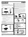
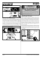
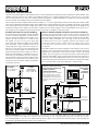
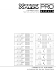
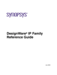
POWER PROCESSING
AMPLIFIERS
On
Protect
ACL
Ch A
Ch B
Active
Signal
Signal
Off
Remote
ACL
CKS 800
Professional Power Amplifier
On
Protect
ACL
Ch A
Ch B
Active
Signal
Signal
Off
Remote
ACL
CKV 80 0
Professional Power Amplifier
On
Protect
ACL
Ch A
Ch B
Active
Signal
Signal
Off
Remote
ACL
CKX 500
Professional Power Amplifier
OWNER’S MANUAL
Important Precautions
This symbol is used to alert the operator to follow important operating
procedures and precautions detailed
in documentation.
This symbol is used to warn operators that uninsulated “dangerous voltages” are present within the equipment enclosure that may pose a risk
of electric shock.
1. Save the carton and packing material
even if the equipment has arrived in
good condition. Should you ever need
to ship the unit, use only the original
factory packing.
2. Read all documentation before operating your equipment. Retain all documentation for future reference.
3. Follow all instructions printed on unit
chassis for proper operation.
4. Do not spill water or other liquids
into or on the unit, or operate the unit
while standing in liquid.
5. Make sure power outlets conform to
the power requirements listed on the
back of the unit.
6. Do not use the unit if the electrical
power cord is frayed or broken. The
power supply cords should be routed so
that they are not likely to be walked on
or pinched by items placed upon or
against them, paying particular attention to cords and plugs, convenience
receptacles, and the point where they
exit from the appliance.
7. Always operate the unit with the AC
ground wire connected to the electrical system ground. Precautions should
be taken so that the means of grounding of a piece of equipment is not
defeated.
8. Mains voltage must be correct and
the same as that printed on the rear
of the unit. Damage caused by connection to improper AC voltage is not covered by any warranty.
9. Have gain controls on amplifiers
turned down during power-up to prevent speaker damage if there are high
signal levels at the inputs.
10. Power down & disconnect units from
mains voltage before making connections.
11. Never hold a power switch in the
“ON” position if it won’t stay there
itself!
12. Do not use the unit near stoves, heat
registers, radiators, or other heat
producing devices.
13. Do not block fan intake or exhaust
ports. Do not operate equipment on a
surface or in an environment which
may impede the normal flow of air
around the unit, such as a bed, rug,
weathersheet, carpet, or completely
enclosed rack. If the unit is used in an
extremely dusty or smoky environment, the unit should be periodically
“blown free” of foreign matter.
14. Do not remove the cover. Removing
the cover will expose you to potentially
dangerous voltages. There are no user
serviceable parts inside.
15. Connecting amplifier outputs to
oscilloscopes or other test equipment
while the amplifier is in bridged mode
may damage both the amplifier and test
equipment!
16. Do not drive the inputs with a signal
level greater than that required to
drive equipment to full output.
17. Do not connect the inputs / outputs
of amplifiers or consoles to any other
voltage source, such as a battery,
mains source, or power supply, regardless of whether the amplifier or console
is turned on or off.
18. Do not run the output of any amplifier channel back into another channel’s input. Do not parallel- or
series-connect an amplifier output
with any other amplifier output.
Crest Audio is not responsible for damage to loudspeakers for any reason.
19. Do not ground any + (“hot”) terminal. Never connect a + (“hot”) output
to ground or to another + (“hot”)
output!
20. Non-use periods. The power cord of
equipment should be unplugged from
the outlet when left unused for a long
period of time.
21. Service Information E q u i p m e n t
should be serviced by qualified service
personnel when:
A. The power supply cord or the plug
has been damaged;
B. Objects have fallen, or liquid has
been spilled into the equipment;
C. The equipment has been exposed to
rain;
D. The equipment does not appear to
operate normally, or exhibits a
marked change in performance;
E. The equipment has been dropped,
or the enclosure damaged.
22. To obtain service, contact your nearest Crest Audio Service Center,
Distributor, Dealer, or Crest Audio at
201.909.8700 (USA).
Power Amplifier Owner’s Manual
Table of Contents.
Introduction . . . . . . . . . . . . . . . . . . . . . . . . . . . . . . . . . . . 2
Quick Set-Up . . . . . . . . . . . . . . . . . . . . . . . . . . . . . . . . . . 3
Unpacking . . . . . . . . . . . . . . . . . . . . . . . . . . . . . . . . . . . . 3
Installation and Mounting . . . . . . . . . . . . . . . . . . . . . . . . 3
Front Panel. . . . . . . . . . . . . . . . . . . . . . . . . . . . . . . . . . . . 3
Side Panels. . . . . . . . . . . . . . . . . . . . . . . . . . . . . . . . . . . . 3
Rear Panel . . . . . . . . . . . . . . . . . . . . . . . . . . . . . . . . . . . . 4
Operation . . . . . . . . . . . . . . . . . . . . . . . . . . . . . . . . . . . . . 4
Input Bay . . . . . . . . . . . . . . . . . . . . . . . . . . . . . . . . . . . . . 6
Input Module Jumpers. . . . . . . . . . . . . . . . . . . . . . . . . . . 6
Network Bay . . . . . . . . . . . . . . . . . . . . . . . . . . . . . . . . . . 7
Power/Output Bay . . . . . . . . . . . . . . . . . . . . . . . . . . . . . . 7
Module Removal . . . . . . . . . . . . . . . . . . . . . . . . . . . . . . . 7
Signal Ground Lift Jumper . . . . . . . . . . . . . . . . . . . . . . . 8
TourClass® Protection Features . . . . . . . . . . . . . . . . . . . . 9
Sequential Turn-On/Off. . . . . . . . . . . . . . . . . . . . . . . . . 10
Service Information . . . . . . . . . . . . . . . . . . . . . . . . . . . . 10
CKS Series Specifications . . . . . . . . . . . . . . . Appendix A
CKV Series Specifications. . . . . . . . . . . . . . . Appendix B
CKX Series Specifications. . . . . . . . . . . . . . . Appendix C
Wire Gauge Charts. . . . . . . . . . . . . . . . . . . . . Appendix D
Distributed/Constant Voltage Systems . . . . . . Appendix E
Crest Audio CK Power Processing Amplifiers
Page 1
Introduction.
Congratulations on your purchase of a Crest Audio CK family of
Power Processing amplifiers. Please read this manual carefully (especially the the “Important Precautions” section located inside the front
cover) as it contains information vital to the safe operation of the
amplifier. Also, please fill out and return the enclosed product registration card.
By combining legendary Crest performance with three unique plug-in
module bays located on the rear panel, these amplifiers can become
very sophisticated audio processors. The CK family is everything that
you expect from Crest Audio. They are ruggedly built from high quality components, intelligently laid out, and possess comprehensive protection features.
The CK Power Processing amplifiers represent new levels of value
and flexibility never before offered to the contracting market. CKS
Series models are specially designed to drive low impedance speaker
loads - down to two ohms with “-2” models,. CKV Series models feature a unique proprietary front end circuit to provide directly coupled
70.7 volt outputs, eliminating the need for step-up transformers. CKX
Series models feature transformer-isolated outputs for 100V operation (50V optional). Together, these amplifiers cover almost every
conceivable installed or distributed sound power requirement.
After-sale support is considered paramount at Crest Audio. For any
assistance in the set-up or operation of this product please call Crest
Audio’s Customer Service department or your local Crest Audio representative. Should you have any problems at all, or suggestions that
may help us improve our products or service, please contact us. We
encourage your participation in Crest’s future. (See back cover for
contact info).
Crest Audio may also be contacted on the World Wide Web at:
http://www.crestaudio.com.
Front View
4U-6.94" / 176mm
CKS1200-2
CKS1600-2
CKV1600
CKV2400
Cooling
Air
3U-5.13" / 130mm
Intake
CKS800 CKX150
CKS800-2 CKX300
CKV800 CKX500
CKX800
2U - 3.44" / 87mm
CKS100
CKS200
CKS400
On
Protect
ACL
ACL
Active
Signal
Signal
CKV100
CKV200
CKV400
Off
CKS 400
Remote
Professional Power Amplifier
19"
1
2 34
5
6
1
7
Side View
4U-6.94" / 176mm
CKS1200-2
CKS1600-2
CKV1600
CKV2400
3U-5.13" / 130mm
CKS800
CKS800-2
CKV800
CKX150
CKX300
CKX500
CKX800
2U - 3.44" / 87mm
CKS100
CKS200
CKS400
CKV100
CKV200
CKV400
Heated Air Exhaust
Heated Air Exhaust
8
17.125"/435mm
Page 2
Crest Audio CK Power Processing Amplifiers
Unpacking.
Front Panel.
Upon unpacking, inspect the amplifier. If you find any damage, notify your supplier immediately. Only the consignee may institute a
claim with the carrier for damage incurred during shipping. Be sure
to save the carton and all packing materials. Should you ever need to
ship the unit back to Crest Audio, one of its offices, service centers,
or the supplier, use only the original factory packing. If the shipping
carton is unavailable, contact Crest to obtain a replacement.
1. Rack Mounting Ears.
Two to four mounting holes are provided on each front mounting
ear.
Amplifier Quick Set-Up.
Crest Audio CK Power Processing amplifiers are configured to a
standard set-up at the factory. They are functional and ready to use
‘out of the box’. All controls and input/output connections are clearly labeled. Units are shipped standard with modules as follows:
Input Bay: CC-IPB Module.
Network Bay: CC-BLK (Blank) Module.
Power/Output Bay: CC-STL Module.
To set the amplifier up for basic usage:
1. Rack mount the amplifier in the location where it is to be used,
remembering to allow for adequate access and cooling space. For
more information, see the sections on Installation, Mounting, and
Cooling Requirements.
2. Make input connections to the input barrier strips on the Input
Module. Be sure to make the correct connections for stereo, parallel, or bridged mono configuration. See the sections on Mode
Configuration and Input Module Connections and Controls for
more information.
3. Connect speakers to the output barrier strips on the Power/Output
Module. Be sure to make the correct output connections for
stereo, parallel or bridged mono configuration. See the section on
Power/Output Module Connections for more information.
4. Make power connections, allowing for proper current draw. See
the section on Connecting Power/Circuit Size Requirements for
more information.
5. Turn the front panel three-position AC switch to 'on', and bring
up the rear panel gain attenuators to the desired levels.
Installation and Mounting.
CK Power Processing amplifiers are 2, 3 & 4-rack space units of 17
1/8" (437mm) depth that mount in a standard 19-inch rack. On all
amplifiers except 4-rack space units, four front panel mounting holes
are provided. (4-rack space units have eight front panel mounting
holes). Rear mounting ears are also provided on all amplifiers for
additional support, which is essential in non-permanent installations
like mobile or touring sound systems, but recommended for permanent installations as well.(Distance from the back of the front rack
ear to the center of the rear mounting ear holes is 16 5/8" / 422mm )
Because of the cables and connectors on the rear panel, a right-angle
or offset screwdriver or hex key will make it easier to fasten the rear
mounting ears to the rails. Dimension drawings are included on page
4.
Crest Audio CK Power Processing Amplifiers
2. Three-position AC Power Switch.
A three-position switch is on the front panel. With the switch pushed
towards the upper position the amplifier is On. The middle position
is Off and the lower position is marked Remote. When switched to
Remote, the amplifier must be activated by the sequential turn
on/turn off (STO) circuit. (CK amplifiers are shipped with the CCSTL Power/Output module standard, which permits STO. If NexSys
compatible modules are used, STO can also be performed under
NexSys computer control.) When a voltage of +8 to +18V DC is
applied to the rear-mounted STO terminal and the “In” terminal is
connected to the “Com” terminal, the amplifier will turn on. When
no voltage is present or the In-Com connection is opened, the amplifier will switch off. Other CK Power Processing amplifiers can be
“daisy-chained” together and will turn on at 200ms intervals. See the
section on Sequential Turn-On/Turn-Off for more information about
STO.
3. Protect LED.
If the amplifier is in Protect mode, the output relay will open, and
this LED will light.
4. Active LED.
The Active LED indicates the amplifier is turned on.
5. Signal LED.
Each channel has a Signal LED, which comes on gradually, first
dim, and then brighter as the signal level increases.
6. ACL LED.
Each channel has an ACL (Active Clip Limiting) LED. This LED
comes on at the clipping point, and indicates that ACL is engaged.
See the section on TourClass Protection for more information.
7. Fan Grill & Filter.
A high-efficiency DC fan (with continuously variable speed) mounted behind the fan filter & fan intake grill draws cooling air into the
amplifier. Do not block this intake! The fan operates only when the
amplifier heatsinks require cooling. Fan filters are easy to remove
and must regularly be cleaned to ensure optimum performance.
Side Panels.
8. Exhaust Ports.
Heated air exits through the exhaust ports, located on the sides of the
amplifier chassis. Do not block these ports when rack-mounting the
amplifier. See Side View.
Page 3
Rear Panel.
Module Bays & Modules.
The rear panel of CK Power Processing amplifiers provides three
bays (Input, Network and Output/Power) configured to accept interchangeable plug-in modules. Your amplifier may have been factoryconfigured with some of the optional modules. In this case, info on
the relevant modules will be enclosed in the amplifier box, or in a
separate binder. If all required information is not included, please
call Crest Audio’s Customer Service department or your local Crest
Audio representative.
About CC Modules and NC Modules.
CC modules fit into the Power/Output or Input module bays in the
rear panel of CK Power Processing amplifiers. These "basic" analog
modules are non-programmable and non-NexSys® compatible; only
the STO function can be controlled (through hardwiring).
NC Modules can be controlled, programmed and/or monitored. They
fit into the rear panel of the amplifiers. NC Input Modules can be
controlled and/or programmed over the NexSys network or via the
N-Coder (Hand-Held) or N-Coder/PC software. (NexSys is Crest
Audio’s hardware and software package that offers network connection of Crest Audio amplifiers and associated devices.). NC Input
and NC Output/Power Modules are NexSys-compatible. Using
NexSys with the appropriate NC Network Module, NC Input and
Output/Power Modules can be controlled, programmed and/or monitored remotely. NexSys also offers a number of diagnostic facilities.
On the NC Input Modules, the individual channel attenuators offer
manual level adjustment and removable knobs for additional security. Except for the STO feature, NC Modules are “tamper-proof” in
that there are no user-accessible setup controls.
9. Circuit Breaker.
A re-settable, protective AC circuit breaker is located at the upper
left of the amplifier rear panel. Two and three rack space amplifiers
have a push-type breaker fitted, while four rack space units have a
throw-switch style breaker. If the breaker has tripped, push it back in
(or, in the case of four rack space units, flip the breaker up) to return
the amplifier to operating condition. If the breaker trips repeatedly,
the amplifier needs servicing.
10. IEC Power Connector with removable Power Cord or
Captive Power Cord.
On two rack space amplifiers, a standard IEC power connector is
located at the lower left corner of the amplifier rear panel. An AC
mains cord having an appropriate AC plug for the intended operating
voltage is included. Three and four rack space units have a captive
power cord.
11. Power/Output Bay.
All Power/Output modules (CC-STL module is shipped standard)
provide a ground lift jumper, barrier strip output connectors, and
connections for sequential turn-on /off (STO) activation.
Rear
View
CLASS 2 WIRING
MAY BE USED
Output
–
+8 to +18VDC
20 mA
LISTED 8B42
COMMERCIAL
POWER
AMPLIFIER
120V~60 Hz 15A
A
+
In
Out
+
Com
A barrier strip is provided for connection of loudspeakers with bare
wire or spade lug connectors. A signal ground lift jumper permits the
audio ground to be lifted from the chassis ground. For more information see the sections on Signal Ground Lift Jumper, Module
Removal, and Sequential Turn-On/Turn-Off.
12. Network Bay.
The CC-BLK (blank panel) comes standard with all amplifiers. See
the section on Replacing or Installing a Network Module for more
information.
13. Input Bay.
CK Power Processing amplifiers come standard with a CC-IPB Input
module. Barrier strip input connectors and individual channel rotary
attenuators are provided. All Input modules have an internal voltage
gain/input sensitivity jumper that is factory-set for X40 gain. See the
sections on Input module Connections and Removing or Replacing
an Input module for more information.
Operation.
Connecting Power/Circuit Size Requirements.
CK Power Processing amplifier power requirements are rated at
“idle”, 1/8th power (“typical” music conditions), 1/3rd power, and
maximum rated power. The maximum power current draw rating is
limited by the amplifier's circuit breaker. Consult the specifications
at the end of this manual for the current that each amplifier will
demand. AC mains voltage must be the same as that indicated on the
rear of the amplifier. Damage caused by connecting the amplifier to
improper AC voltage is not covered by any warranty. Note: Always
turn off and disconnect the amplifier from the mains voltage before
making audio connections. If possible, as an extra precaution, have
the attenuators turned down during power-up.
Cooling Requirements.
CK Power Processing amplifiers use a forced-air cooling system to
maintain a low, even operating temperature. Drawn by a continuously-variable-speed fan mounted behind the front panel, air enters
through the front grill and courses through the cooling fins of the
heat sink, (which dissipates power transistor heat), before exiting
through the side panel ports. The fan will remain inactive until operating temperature rises above 45° C. Make sure that there is enough
space around the front of the amplifier to allow air to enter, and
around the sides to allow the heated air to exit. (See page 4 for intake
and exhaust locations. Note: If the amplifier is rack-mounted, do not
use doors or covers on the front or rear without pressurizing the
rack. Whatever type of rack you are using, make sure that heated air
can escape freely, and that there is no resistance to the intake of cool
air through the front grill. Intake and exhaust air must flow without
resistance. Ensure that fan filters are regularly cleaned and periodically replaced. (No tools are required for filter removal).
Model
Name
Output Power
@70.7V
Model
Name
Output Power
@8Ω/Ch.
CKV 100
CKV 200
CKV 400
CKV 800
CKV 1600
CKV 2400
50W
100W
200W
400W
800W
1200W
CKS 100
CKS 200
CKS 400
CKS 800
CKS 800-2
CKS 1200-2
CKS 1600-2
50W
100W
200W
400W
400W
600W
800W
Signal
Ground
Lift
Jumper
9 10
Page 4
11
0
Input A
Model
CC-BLK
–
Model
CC-STL
2
1
Designed & manufactured in the USA by:
B
NEC
CLASS 2 ONLY
Level
4 5 6
A 3
7
+
–
2
1
–
0
Crest Audio Inc.
100 Eisenhower Dr.
Paramus, New Jersey 07652 USA
12
Input B
+
8
9
10
Level
4 5 6
B 3
7
8
9
10
Model
CC-IPB
13
Crest Audio CK Power Processing Amplifiers
PowerSave.
All CK Power Processing amplifiers come standard with PowerSave
circuitry. This effectively reduces current draw and thermal emissions to a minimum when the amplifier is at idle. PowerSave operates by cutting off the bias current to the output stage after signal
absence is sensed at the input. Once signal is present, PowerSave
instantly restores the bias current after the first positive-going waveform. Current draw specifications while PowerSave is active are
included in specifications under "Idle Current Draw."
Thermal Emissions.
System cooling needs must be considered before installation, and the
system installer/designer should specify appropriate countermeasures, such as ventilation, air conditioning, etc. Refer to the specifications appendix at the back of this manual for specific thermal
emissions figures.
Mode Configuration.
CK Power Processing amplifiers are configured standard for two
channel (stereo) operation. They can, however, be wired to operate
in bridged mono mode (a single Mono input amplified to the combined power of both channels and made available as a single Mono
output) or parallel mode (where a single Mono input signal is fed to
both channels).
Two Channel (Stereo) Mode.
In the factory configured, standard two channel (stereo) mode, both
channels operate independently, individual input attenuators controlling their respective levels. Signal at Channel A’s input produces
output at Channel A’s output, while signal at Channel B’s input produces output at Channel B’s output. (Recommended minimum nominal load impedance for stereo operation of CKS Series amplifiers is
4 ohms per channel; 2 ohms per channel for models CKS 800-2,
1200-2, and 1600-2. CKV and CKX Series amplifiers are specifically designed for use with distributed or constant voltage systems. See
appendix E for information on recommended distributed line impedance.). Connect loudspeakers to the barrier strip output connectors
for channels A and B. Connections are shown in the diagram below.
Parallel Mode.
To send the same signal to both channels, connect the input signal to
Channel A via the Input Barrier Strip. Run jumpers from the positive
and negative terminals of Channel A’s Input Barrier Strip to the
respective terminals of Channel B’s. Both channels then share
Channel A’s input signal, but will operate independently. Speakers
are connected as in Stereo Mode.
Parallel Mode Diagram
- +
CLASS 2 WIRING
MAY BE USED
Output
+8 to 18VDC
20 mA
LISTED 8B42
COMMERCIAL
POWER
AMPLIFIER
120V~60 Hz 15A
Level
4 5 6
A 3
7
–
2
1
A
+
+
Input A
+
B
NEC
CLASS 2 ONLY
Input B
+
–
Level
4 5 6
B 3
7
2
1
–
–
Model
CC-IPB
Model
CC-STL
- +
+ -
Bridged Mono Mode - CKS Series Power Amplifiers.
Bridged Mono Mode straps both amplifier channels together, making
a very powerful single channel amplifier. One channel “pushes” and
the other “pulls” equally, effectively quadrupling the power over that
of either channel alone. Signal is connected to the input barrier strip
as shown in the drawing below, with one jumper connecting the positive (+) terminal of Input A to the negative (-) terminal of Input B,
and another jumper connecting the negative (-) terminal of Input A
to the positive (+) terminal of Input B. Both channel attenuators
(A&B) are used to control signal level, and both must at the same
level, preferably at 0dB attenuation. The speakers are connected only
to the designated “+” output terminals as shown below.
Note: Use extreme caution when operating in bridged mono mode.
Never ground either side of the speaker cable when the amplifier is
in bridged mono mode; both sides are “hot.” If an output patch
panel is used, all connections must be isolated from each other and
from the panel. For CKS Series amplifiers, the recommended minimum nominal load impedance in bridged mono mode is 8 ohms, the
equivalent to driving both channels at 4 ohms. [For models CKS
800-2, 1200-2 and 1600-2, the recommended minimum nominal load
impedance in the bridged mono mode is 4 ohms, equivalent to driving both channels at 2 ohms].
Note: Driving loads of less than the recommended minimums will
activate the IGM circuitry, resulting in a loss of power, and may also
cause a thermal protect condition.
Bridged Mono Mode Connection Diagram.
CLASS 2 WIRING
MAY BE USED
Output
+8 to 18VDC
20 mA
LISTED 8B42
COMMERCIAL
POWER
AMPLIFIER
In
120V~60 Hz 15A
Out
Level
4 5 6
A 3
7
–
2
1
A
+
0
+
Com
Input A
B
NEC
CLASS 2 ONLY
+
–
Input B
+
8
9
10
Level
4 5 6
B 3
7
2
1
–
–
0
8
9
10
Model
CC-IPB
Model
CC-STL
- +
- +
8
9
10
0
Signal
Ground
Lift
Jumper
Signal
Ground
Lift
Jumper
Stereo Mode Connection Diagram
8
9
10
0
In
Out
Com
+ Ch.A
CLASS 2 WIRING
MAY BE USED
Output
+8 to 18VDC
20 mA
LISTED 8B42
COMMERCIAL
POWER
AMPLIFIER
In
120V~60 Hz 15A
Out
Level
4 5 6
A 3
7
–
2
1
A
+
0
+
Com
Input A
B
NEC
CLASS 2 ONLY
+
–
Input B
+
2
1
–
–
0
Signal
Ground
Lift
Jumper
Model
CC-IPB
Model
CC-STL
- +
+ -
+ -
Regardless of operating mode, NEVER
connect amplifier outputs together!
Crest Audio CK Power Processing Amplifiers
8
9
10
Bridged Mono Mode - CKV & CKX Series.
Level
4 5 6
B 3
7
8
9
10
CKV and CKX Series amplifiers can also be
wired for Bridged Mono mode operation.
However, bridging these models is usually undesirable, as the resultant output will be approximately 140V (CKV) or 200V (CKX)! There are,
however, specific applications for this configuration. Contact Crest Audio Customer Service for
more information if required.
Page 5
Input Bay.
Input Module Connections and Controls.
Input barrier strips have a 0.325" (8.3mm) center and 0.270"
(6.9mm) lug space. For connecting to the input barrier strips, a wire
gauge between 14 AWG (2.5mm2) & 24 AWG (0.25mm2), and spade
lugs (Panduit Part No. PNF 18-6LF-C or equivalent) are recommended.
Input Module Connections and Controls Diagram.
SEE INSTRUCTION MANUAL
Level
4 5 6
A
3
7
2
1
0
Input A
+
–
Input B
+
8
9
10
Level
4 5 6
B
3
7
2
1
–
0
8
9
10
Model
CC-IPB
Input Level
Attenuators
Input Barrier Strip
Removable Attenuator Knobs.
The attenuator knobs can be removed and replaced with blanking
plugs. These plugs are shipped with the amplifier. The procedure for
attenuator knob removal is as follows:
1. With an X-Acto or similar knife, pop off the grey key cap of
the attenuator knob. This will reveal the inside nut.
2. Using a needle nose pliers or appropriate size nut driver,
loosen the inside nut.
3. Slide the attenuator knob off the shaft.
4. Insert a regular screwdriver in the slotted end of the shaft, and
adjust attenuation to desired level.
5. Blanking plugs may now be inserted in the attenuator holes.
Unbalanced Sources.
For use with an unbalanced source, tie the inverting (minus) input to
ground by installing a jumper across the appropriate barrier strip terminals. If the inverting input is left floating, a 6 dB loss in gain will
result. See the diagram below.
all input NC modules), labeled “W1 W2 W3”, are used to set the
overall gain of the amplifier. The 3 positions allow the amplifier to
be set for constant gain of X20 (26 dB), X40 (32 dB), OR constant
sensitivity for full output (.775V) at 0 dBu input. The standard factory setting is for X40 (32dB). (Refer to the specifications for more
gain/sensitivity information). The diagram below shows the location
of these jumpers. All jumpers must be set to the same position as
indicated in the drawing below. To change jumper settings, the Input
module must first be removed from the amplifier chassis. This operation is covered in the section "Module Removal/Replacement".
N-Coder Setup Jumpers.
All NC Modules have internal jumpers used to set the module for
operation with NexSys or N-Coder. These jumpers are labeled “W4
W5” on the Input module circuit board. The “NC-NXS” jumper position allows operation with NexSys, while the “NCODE” jumper
position permits the Input module to be programmed through NCoder or N-Coder/PC software when the amplifier is off . Note:
Factory setting is the 'NexSys' position. If NexSys, N-Coder, or NCoder/PC software is not being used, jumper position will have no
effect upon the operation of the amplifier.
Gain Select Jumpers Diagram.
Channel A Jumper
Channel B Jumper
NexSys Indicator Jumper (NC-IPN Only)
+26dB
0dBu
+32dB
+26dB
0dBu
+26dB
+32dB
0dBu
+32dB
.775V / 0 dBu (For Full Power)
+26dB
0dBu
B
+32dB +26d
0dBu
+32dB
+26dB
0dBu
+32dB
X40 (+32dB) Standard Factory Setting
X20 (+26 dB)
N-Coder/NexSys Setup Jumpers Diagram.
N-CODE
NC-NXS
N-CODE
NC-NXS
N-Coder Setup
NexSys Setup
Input Module Jumpers Location Diagram - CC-IPB.
CREST AUDIO
26C2197-02
Input Balanced /Unbalanced Connections Diagram.
+26dB
0dBu IN
+32dB
SEE INSTRUCTION MANUAL
Level
4 5 6
A
3
7
2
1
0
Input A
+
–
Input B
+
W1
W2
8
9
10
A
B
Level
4 5 6
B
3
7
2
1
–
0
8
9
10
Input Gain/Sensitivity Jumpers
Model
CC-IPB
Balanced
Input
+ –
Unbalanced
Input
Input Module Jumpers.
Gain Select Jumpers.
Input modules have user-settable jumpers to configure Input
Gain/Sensitivity. These internal jumpers (two for CC-IPB, three for
Page 6
CREST AUDIO
26C2797-02
+ –
Input Module Jumpers Location Diagram - NC-IPN shown.
Input Gain/Sensitivity Jumpers
W2 W1 W3
+26dB
0dBu Sen
+32dB
N-CODE
NC-NXS
W4 W5
Nexsys / N-Coder Jumpers
Crest Audio CK Power Processing Amplifiers
Network Bay.
Network Module Controls/Connections.
CK Power Processing amplifiers come standard with a blanking
panel fixed over the Network bay. When a Network module is
installed in this bay, network connection is made via a pair of threepin connectors. They are wired in parallel, and form a loop-through
connection. (Mates for these connectors are shipped with the
Network module.) Network bus addressing is accomplished through
use of the Hi and Lo Address dials. Refer to module documentation
for exact connection and control information.
If Load Monitoring is
employed, an additional ribbon
cable will be located here.
Network Bay Controls/Connections Diagram.
Designed & manufactured in the USA by:
Crest Audio Inc.
100 Eisenhower Dr.
Paramus, New Jersey 07652 USA
Model
Name
Output Power
@70.7V
Model
Name
Output Power
@8Ω/Ch.
CKV 100
CKV 200
CKV 400
CKV 800
CKV 1600
CKV 2400
50W
100W
200W
400W
800W
1200W
CKS 100
CKS 200
CKS 400
CKS 800
CKS 800-2
CKS 1200-2
CKS 1600-2
50W
100W
200W
400W
400W
600W
800W
Network
6
5 4 3 2
6
DCBA
DCBA
9 8 7
NexSys Network
Connectors
Hi
E
+ –
Input Module
General Module Setup Diagram.
Model
NC-NXS
1 0 F
E
5 4 3 2
1 0 F
9 8 7
Data
+ –
Network Module
Address
Lo
Amplifier is shown with the top cut away for
clarity only. Dangerous voltages exist inside,
and only a Crest Audio-certified service
technician should remove top cover !
Network Bus
Address Selectors
Power/Output Bay.
Power/Output Module Connections.
Speakers are connected using the Output Barrier Strip connectors.
Spade lugs, ring tongues or bare wire may be connected to the output
barrier strip elements. Spade Lug measurements for Output barrier
strip are as follows: .44" (11mm) screw spacing, .32" (8mm) lug
space. For output spade lugs, Panduit Part No. PNF 14-8LF-C (or
equivalent) is recommended. (Consult the wire gauge charts in theis
manual for speaker wiring recommendations.) Make sure the amplifier is turned off before you change any output connections or
jumpers. Also ensure that the load impedance being connected is not
less than the amplifier's ability to drive it.
On the standard CC-STL Power/Output module, a four-pin
Sequential Turn-On/Turn-Off (STO) connector is suppled. A mating
connector is shipped with the amplifier. For more information on
STO, see the section on Sequential Turn-On/Off.
The amplifier must be switched off and the
mains plug removed from the supply before
module removal operation is undertaken.
Removing or Replacing an Input Module.
The amplifier must be switched off and unplugged from the mains
supply before this operation is undertaken. Remove the four #8 3/8"
Phillips pan head sheet metal screws that secure the module to the
chassis. The module is connected electrically to the amplifier via
multi-pin ribbon cables. Unplugging the module from the ribbon
cable connectors frees the module for removal. To insert the same or
another module, simply reverse this procedure, making sure that any
ribbon cable connectors are properly and securely seated. Note: The
amplifier must not be operated without an Input module in place.
Input Module Removal Diagram - CC-IPB.
S 2 WIRING
BE USED
put
Power/Output Module
Connections Diagram.
CLASS 2 WIRING
MAY BE USED
Output
+8 to 18VDC
20 mA
Output Power
@70.7V
Model
Name
Output Power
@8Ω/Ch.
50W
100W
200W
400W
800W
1200W
CKS 100
CKS 200
CKS 400
CKS 800
CKS 800-2
CKS 1200-2
CKS 1600-2
50W
100W
200W
400W
400W
600W
800W
Designed & manufactured in the USA by:
–
Model
CC-BLK
A
+
al
nd
per
In
Out
Model
Name
CKV 100
CKV 200
CKV 400
CKV 800
CKV 1600
CKV 2400
Crest Audio Inc.
100 Eisenhower Dr.
Paramus, New Jersey 07652 USA
+
Com
B
NEC
CLASS 2 ONLY
–
Signal
Ground
Lift
Jumper
Model
CC-STL
SEE INSTRUCTION MANUAL
Level
4 5 6
A
3
7
2
1
Output Barrier Strip
Sequential Turn-On/Off
(STO) Connector
0
Input A
+
–
Input B
+
8
9
10
Level
4 5 6
B
3
7
2
1
–
0
8
9
10
Model
CC-IPB
Module Removal.
Removable modules contain static-sensitive
devices; handle modules at static-safe work
stations!
Situations Requiring Module Removal
Only jumper setting changes or module upgrades require modules to
be removed from the amplifier. Contact Crest Audio Customer
Service for full details on module removal. The ‘General Module
Setup’ diagram indicates the general setup of the rear panel
module/bay configuration.
Crest Audio CK Power Processing Amplifiers
Page 7
IMPORTANT:
THE POWER/OUTPUT
MODULE IS NOT REMOVABLE. DO NOT
ATTEMPT TO REPLACE OR REMOVE A
POWER/OUTPUT MODULE !
Input Module Replacement Diagram - NC-IPN.
Designed & manufactured in the USA by:
Crest Audio Inc.
100 Eisenhower Dr.
Paramus, New Jersey 07652 USA
WIRING
E USED
ut
Model
Name
Output Power
@70.7V
Model
Name
Output Power
@8Ω/Ch.
CKV 100
CKV 200
CKV 400
CKV 800
CKV 1600
CKV 2400
50W
100W
200W
400W
800W
1200W
CKS 100
CKS 200
CKS 400
CKS 800
CKS 800-2
CKS 1200-2
CKS 1600-2
50W
100W
200W
400W
400W
600W
800W
Network
Address
Data
5 4 3 2
6
9 8 7
6
Model
NC-NXS
1 0 F
DCBA
9 8 7
Hi
DCBA
+ –
E
5 4 3 2
1 0 F
E
+ –
Lo
This module can only be serviced by a Crest Audio-certified
service technician. Please consult your dealer or Crest Audio
representative for assistance. User-inflicted damage to this
module will invalidate your warranty.
Ribbon Cable from
Network Module, if fitted
SEE INSTRUCTION MANUAL
Level
4 5 6
A 3
7
N-Coder
Data
Port
2
1
0
+
–
+
8
9
10
Level
4 5 6
B 3
7
Input B
Input A
2
1
–
0
8
9
10
Signal Ground Lift Jumper.
Model
NC-IPN
Whenever possible, the signal source equipment should share the
same AC ground as the amplifier(s). In some cases, however, particularly if an amplifier is being installed in an existing system, this
may result in a ground loop. If this happens, remove the factoryinstalled ground lift jumper from the output barrier strip (located on
the Power/Output module), which electrically connects the signal
ground to the chassis/AC ground. If the jumper is removed, the signal ground is lifted and is clamped to ± 0.6V. Don’t remove the
jumper if the amplifier and the signal source equipment are not on
the same AC ground!
Replacing or Installing a Network Module.
The amplifier must be switched off and unplugged from the AC
mains supply before this operation is undertaken. Four Phillips head
screws secure the module to the chassis. The module is connected
electrically to the amplifier via multi-pin ribbon cables. Unplugging
the module from the ribbon cable connectors frees the module for
removal. To insert the same or another module, simply reverse this
procedure. Note: Standard CK Power Processing amplifiers come
with a blank panel installed in the Network bay. The amplifier must
not be operated without a Network module or blank panel in place.
Network Module Installation Diagram.
SEE INSTRUCTION M
CLASS 2 WIRING
MAY BE USED
Output
+8 to 18VDC
20 mA
N-Coder
Data
Port
–
A
+8 to 18VDC
240 mA
Error
+
PUSH
+
B
NEC
CLASS 2 ONLY
In a properly designed system (for safety and to minimize noise), the
amplifier should receive its ground from the AC line cord. The shield
on a balanced input line should be grounded at one end only (usually
the sending end), and it must never be relied on to supply AC ground
to the amplifier.
AES/EBU
In
A
Inpu
+
–
–
+
Signal
Ground
Lift
Jumper
Model
CC-STL
Signal Ground
Lift Jumper
In
Out
+
Designed & manufactured in the USA by:
Crest Audio Inc.
100 Eisenhower Dr.
Paramus, New Jersey 07652 USA
Model
Name
Output Power
@70.7V
Model
Name
Output Power
@8Ω/Ch.
CKV 100
CKV 200
CKV 400
CKV 800
CKV 1600
CKV 2400
50W
100W
200W
400W
800W
1200W
CKS 100
CKS 200
CKS 400
CKS 800
CKS 800-2
CKS 1200-2
CKS 1600-2
50W
100W
200W
400W
400W
600W
800W
Network
5 4 3 2
–
Signal
Ground
Lift
Jumper
DCBA
9 8 7 6
9 8 7 6
Hi
DCBA
+ –
E
+ –
Model
NC-NXS
1 0 F
E
5 4 3 2
1 0 F
B
NEC
CLASS 2 ONLY
Address
Data
Com
Lo
Model
CC-STL
Page 8
Crest Audio CK Power Processing Amplifiers
TourClass® Protection Features.
Every model in the CK Power Processing incorporates TourClass
protection features. Derived from Crest’s extensive experience with
the world’s largest sound rental companies, the TourClass group of
circuits sets new standards in load and amplifier protection.
ACL (Active Clip Limiting).
At the amplifier’s full power, or clipping point, ACL will be activated. This is indicated by illumination of the Clip/ACL LED. The
channel gain will automatically be reduced, guarding the loudspeakers against damaging high power and continuous square waves that
would otherwise be produced. Situations that may activate ACL
include: uncontrolled feedback, oscillations, or an improper equipment setting or malfunctions upstream from the amplifier. Normal
program transients will not trigger ACL; only steady or excessive
clipping will. ACL is virtually transparent in operation and full signal bandwidth is maintained. If NexSys control is installed, ACL
operation is reported to NexSys.
IGM Impedance Sensing.
IGM (Instantaneous Gain Modulation) is an innovative circuit that
allows the amplifier to operate safely into any load. When the amplifier sees a load that overstresses the output stage, the IGM circuit
adjusts the channel gain to a safe level. Like ACL, the IGM circuit is
inaudible in normal use. In addition, if extreme low impedance is
encountered, the amplifier’s output relay will open. If NexSys control is installed, IGM operation is reported to NexSys.
AutoRamp Protection.
AutoRamp operates every time the amplifier is turned on or is reactivated after a protect condition. This exclusive Crest feature gradually
increases gain to the attenuator setting after the output relays close,
avoiding unnecessary stress on the loudspeakers.
Thermal Protection.
If the heatsink temperature reaches an abnormally high temperature,
the amplifier will protect itself by disconnecting speakers and shutting down until sufficiently cooled. During this time, the Protect
LED will light. If the power transformer gets too hot, its thermal
sensing circuit will disconnect both channel outputs. During this
time, the Active LED will extinguish, the Protect LED will illuminate, and ACL LEDs will stay off, and the cooling fan will stay running. Once cool enough, the amplifier will resume operation automatically. If NexSys control is installed, thermal protect operation is
reported to NexSys.
Short Circuit.
If an output is shorted, the IGM and thermal circuits will automatically protect the amplifier. The IGM circuit senses the short circuit
as an extremely stressful load condition and attenuates the signal,
protecting the channel’s output transistors from overcurrent stress. If
the short circuit remains, the load will be disconnected by the thermal protection circuitry.
DC Voltage Protection.
If an amplifier channel detects DC voltage at its output terminals, the
output relay will immediately open to prevent loudspeaker damage.
The Protect LEDs will light. If NexSys control is installed, a DC protect condition is reported to NexSys.
Crest Audio CK Power Processing Amplifiers
Page 9
Sequential Turn-On/Turn-Off.
CK Power Processing amplifiers come standard with the CC-STL Sequential Turn-On/Turn-Off (STO) Output/Power module installed. If the
amplifier front power switch is set to “remote” and a voltage of between +8 to +18 VDC is applied across the “Com” and “+8 to +18V” terminals, a closure between the “In” and “Com” terminals will turn the amplifier on. Additional amplifiers are added to the chain by looping from
the "Out" terminal of one amplifier into the "In" terminal of the next amplifier.
Turn-on delay time between amplifiers fitted with basic modules (i.e., CC-STL) is approximately 100ms, turn-off delay time is 200ms. (When
using NexSys-controlled Power/Output modules, these standard turn-on and turn-off delay times may be modified in the software). The number
of CC-STL modules that an external DC supply will be able to power is dependent on the supply's voltage output and current capability. The
external Direct Plug-In Power Supply Unit (CC-WW1, available from Crest Audio) supplies 9 volts at 300 milliamps and can power 15 CCSTL modules. If your configuration requires the STO control of more than 15 amplifiers, contact Crest Audio.
Standard Sequential Turn-On/Turn-Off Wiring.
For CK Power Processing amplifier systems configured
for basic non-NexSys applications, (CC-IPB with CCSTL) an external Direct Plug-In Power Supply Unit is
needed to provide a nominal +8 to +18 Volts to each
STL module. Use only a two-wire power supply! This
power supply (part number CC-WW1) may be ordered
from Crest Audio . (Note that module CC-SDC has an
integral STO power supply, and does not require CCWW1). The “Com” and “+8 to+18V” terminals on each
CK Power Processing amplifier are bussed together in
parallel and connected to the DC supply. The “Out” terminal of each CK amplifier is connected to the “In” terminal of the next CK amplifier in the turn-on sequence.
The first amplifier in the chain requires an SPST closure
between it’s “In” terminal and “Com” terminal to initiate the power turn-on sequence and keep the amplifiers
in the chain powered on.
Standard Sequential
Turn-On/Off
(max. # of amplifiers is
15 per CC-WW1)
CC-WW1
Direct Plug-In
Power Supply Unit
+8 (min) to +18VDC (max)
+8 to 18VDC
20 mA
LISTED 8B42
COMMERCIAL
POWER
AMPLIFIER
120V~60 Hz 15A
Manual or NexSys-Compatible Sequential Turn-On/Turn-Off Wiring.
CK Power Processing amplifiers fitted with a NexSys-compatible NC
Power/Output Module (NC-STI, NC-SAC, NC-SLM) may be powered up via
NexSys OR with a manual switch closure. If NexSys is employed, the STO delay
time is also software-controllable. Note: when using NexSys control, hard-wiring
for manual switch closure between amplifiers should be used cautiously. If the
switch closure output is wired up, it WILL ¨cause the next amp to switch, regardless of which source (hardware switch or NexSys STO command) has initiated
the command.
The modules (and the non-NexSys compatible CC-SIO) feature a 6-pin connector
providing a 3-wire input from switch closures (or from a CK Power Processing
amplifier) and an opto-isolated 3-wire output to another CK Power Processing
amplifier. The 3-wire signals are: ON, OFF, and COM. To initiate either the ON
or OFF function manually, simply provide a closure from the proper signal line to
COM; after a time delay of approximately 200ms, the closure is echoed on the 3
isolated output signal pins to initiate the turn-on function in 'downstream' amplifiers. The on/off closures can be either momentary or constant contact.
Manually Initiated (hard-wired)
Sequential Turn-On/Off using
NexSys-compatible
Power/Output Modules
When employing NexSys-compatible
Power/Output modules, use either
NexSys-initiated Sequential TurnOn/Off OR (three-wire) hard-wired
Sequential Turn-On/Turn-Off; NOT
BOTH!
On Off
NexSys-Initiated Sequential TurnOn/Off using NexSys-compatible
Power/ Output
Modules
(unlimited #
®
of amplifiers)
PC
In
Out
Com
Output
NEC
CLASS 2 ONLY
NC-NXS
In
On
Com
Off
On
Com
Off
Out
Output
+8 to 18VDC
20 mA
LISTED 8B42
COMMERCIAL
POWER
AMPLIFIER
In
120V~60 Hz 15A
Out
In
NC-NXS
On
Com
Com
Off
On
Com
NEC
CLASS 2 ONLY
Off
Out
Service Information. For service, contact your nearest Crest Audio Service Center, Distributor, Dealer, or any of the worldwide Crest Audio
offices, or contact Crest Audio Inc. Customer Service directly at: T EL . 201.909.8700 (USA) Fax. 201.909.8744 (USA).
For technical inquiries only, the Crest Audio Technical Services Dept. can be faxed at 201.587.0550 (USA). Crest Audio may also
be contacted on the World Wide Web at: http://www.crestaudio.com.
Page 10
Crest Audio CK Power Processing Amplifiers
Appendices
Appendix A - CKS Series Specifications.
CKS100
CKS200
CKS400
CKS800
CKS800-2
CKS1200-2
8Ω Stereo Power, 20Hz-20kHz, 0.1% THD+N
50 Watts
100 Watts
200 Watts
400 Watts
400 Watts
600 Watts
700 Watts
8Ω Stereo Power, 1kHz, 0.01% THD+N
60 Watts
120 Watts
255 Watts
440 Watts
420 Watts*
620 Watts*
715 Watts*
4Ω Stereo Power, 20Hz-20kHz, 0.1% THD+N
75 Watts
150 Watts
300 Watts
600 Watts
600 Watts
900 Watts
1100 Watts
4Ω Stereo Power, 1kHz, 0.01% THD+N
90 Watts
175 Watts
320 Watts
670 Watts
670 Watts*
940 Watts*
1130 Watts*
2Ω Stereo Power, 20Hz-20kHz, 0.1% THD+N
N/A
N/A
N/A
N/A
800 Watts
1100 Watts
1100 Watts
2Ω Stereo Power, 1kHz, 0.1% THD+N
N/A
N/A
N/A
N/A
870 Watts
1130 Watts
1440 Watts
Max RMS Output Voltage (each channel)
22V
32V
45V
64V
64V
78V
90V
Peak Output Voltage (each channel)
31V
45V
64V
90V
64V
110V
127V
10Hz–20kHz, -3dB @148kHz
Frequency Response (+0 / -0.3dB, 1W/8Ω)
10Hz–20kHz, +0/-0.2dB
Power Bandwidth (rated power at 4Ω, 1% THD+N)
ACL, IGM, AutoRamp, short circuit, DC voltage, turn-on/off transient, current inrush, and sub/ultrasonic input.
TourClass® Protection
THD+N (rated power at 4Ω, 1kHz)
<0.01%
<0.01%
<0.01%
<0.01%
300:1
300:1
300:1
0.5V
0.707V
1.0V
400:1
400:1
400:1
1.41V
1.732V
1.87V
H
H
1.41V
X40 standard, X20 & 0.775V user-selectable
Input Impedance (balanced, unbalanced)
>20kΩ, >10kΩ
Hum and Noise (below rated power @ 4Ω)
105dB, A-weighted
>60dB @ 1kHz
Crosstalk (below rated power @ 4Ω)
AB
AB
AB
AB
H
Rear-panel barrier strip input, 4-pin Phoenix sequential turn-on/off connector on standard CC-STL module
Input Connectors (per channel)
Rear-panel barrier strip output
Output Connectors (per channel)
Filter Storage
<0.02%
>60dB
Voltage Gain
Class
<0.02%
400:1
Input CMRR (1kHz)
Input Sensitivity (rated power at 8Ω, @ X40 gain)
<0.02%
<0.1%
SMPTE IMD (rated power at 8Ω, 60Hz & 7kHz)
Damping Factor
CKS1600-2
10,000 µF
22,000 µF
16,400 µF
24,000 µF
24,000 µF
27,500 µF
37,000 µF
1.3A
100–240V, 50–60Hz
Power Supply (factory configured)
Idle Current Draw (PowerSave active, 120V)
0.5A
0.6A
0.7A
0.7A
0.7A
1.3A
1/8 Power Current Draw (typical music, 120V/4Ω)
1.65A
3.0A
5.8A
10A
4.2A
9.6A
10A
1/3 Power Current Draw (cont. music, 120V/4Ω)
2.32A
4.2A
8.6A
14.8A
12.1A
17.3A
22.6A
3.5A
6.5A
12A
15A
20A
26A
30A
Thermal Emissions (1/8 Power, 4Ω)
612 BTU/hr
1100 BTU/hr
2120 BTU/hr
3584 BTU/hr
1210 BTU/hr
3164 BTU/hr
3154 BTU/hr
Thermal Emissions (1/3 Power, 4Ω)
780 BTU/hr
1380 BTU/hr
2820 BTU/hr
4700 BTU/hr
3600 BTU/hr
5040 BTU/hr
6525 BTU/hr
Max Current Draw (circuit brkr rating, 120V/4Ω)
Cooling
Variable speed, front panel mounted fan, front-to-side airflow
Controls
Three-position front panel On/Remote/Off switch, two rear panel channel attenuators, AC mains circuit breaker
Signal, ACL (one per ch.) Protect, Active
LED Indicators (per channel)
Steel Chassis, 16 gauge, double thickness in rack ear area.
Construction
Dimensions (Height x Width x Depth) 3.5"x19.0"x17.13" 3.5"x19.0"x17.13"
89x483x435mm
89x483x435mm
Gross Weight
31.63 lbs. (14.36 kg) 34.44 lbs. (15.64 kg)
Net Weight
26.63 lbs. (12.09 kg) 29.44 lbs. (13.37 kg)
Warranty
3.5"x19.0"x17.13"
5.25"x19.0"x17.13"
5.25"x19.0"x17.13"
7.0"x19.0"x17.13"
89x483x435mm
133x483x435mm
133x483x435mm
178x483x435mm
7.0"x19.0"x17.13"
178x483x435mm
35.44 lbs. (16.09 kg)
58.20 lbs. (26.42 kg)
58.20 lbs. (26.42 kg)
78.65 lbs. (35.39 kg)
78.65 lbs. (35.39 kg)
30.44 lbs. (13.82 kg)
50.20 lbs. (22.80 kg)
50.20 lbs. (22.80 kg)
70.65 lbs. (32.08 kg)
70.65 lbs. (32.08 kg)
5 Years (USA, Canada, United Kingdom, and many other countries)
* 0.02% THD+N
Voltage Gain / Input Sensitivity Options
CKS100
9/4/97
Factory Standard (“+32dB”)
Option 1 (“+26dB”)
Option 2 (“0dBu”)
Gain
X40
X20
X25.8
Sens
0.5V
1.0V
.775V
CKS200
Gain
X40
X20
X36.5
Sens
0.70V
1.41V
.775V
CKS400
Gain
X40
X20
X51.6
Sens
1.0V
2.0V
.775V
CKS800
CKS800-2
CKS1200-2
CKS1200-2
Gain Sens
X40 1.41V
X20 2.82V
X73 .775V
Gain Sens
X40 1.41V
X20 2.82V
X73 .775V
Gain
X40
X20
X89.4
Gain
X40
X20
X96.5
Sens
1.73V
3.46V
.775V
Sens
1.87V
3.74V
.775V
Power figures are watts per channel, both channels driven
Crest Audio reserves the right to make improvements in manufacturing or design which may affect specification
Crest Audio specification literature is available in downloadable PDF format; visit our website at http://www.crestaudio.com
©1997 Crest Audio Inc.
Appendix A
Crest Audio CK Power Processing Amplifiers
Appendix B - CKV Series Specifications.
Output Power, 70.7 Volt
CKV100
CKV200
CKV400
50 Watts
100 Watts
200 Watts
CKV800
400 Watts
1200 Watts
130V
Peak Output Voltage (each channel)
10Hz –20kHz, -3dB @ 148kHz
Frequency Response (+0 / -0.3dB, 1W/70.7V)
10Hz –20kHz, +0/-0.2dB
Power Bandwidth (full power, 1% THD+N)
TourClass® Protection
ACL, IGM, AutoRamp, short circuit, DC voltage, turn-on/off transient, current inrush, and sub/ultrasonic input.
<0.1%
THD+N (rated power, 1kHz)
SMPTE IMD (rated power, 60Hz & 7kHz)
<0.1%
Input CMRR (1kHz)
> 60 dB
1.75V @ X40 gain setting
Input Sensitivity (rated power)
X40 standard, X20 & 0.775V user-selectable
Voltage Gain
>20kΩ/>10kΩ
Input Impedance (balanced, unbalanced)
105dB, A-weighted
Hum and Noise (below rated power)
>60dB @ 1kHz
Crosstalk (below rated power)
AB
AB
AB
AB
H
H
Rear panel barrier strip input, 4-pin Phoenix sequential turn-on/off connector on standard CC-STL module
Input Connectors (per channel)
Rear panel barrier strip output
Output Connectors (per channel)
Filter Storage
CKV2400
800 Watts
92V
Max RMS Output Voltage (each channel)
Class
CKV1600
3,900 µF
3,900 µF
7,800 µF
11,200 µF
37,000 µF
37,000 µF
1.3A
100V–240V, 50–60Hz
Power Supply (factory configured)
Idle Current Draw (PowerSave active, 120V)
0.5A
0.5A
0.6A
0.8A
1.3A
1/8 Power Current Draw (typical music, 120V)
0.76A
2.2A
3.6A
7.0A
8.0A
10A
1/3 Power Current Draw (cont. music, 120V)
1.02A
2.83A
5.1A
10.1A
17.0A
23.0A
2.5A
4.2A
7.0A
15A
30A
30A
Thermal Emissions (1/8 Power, 120V)
269 BTU/hr
816 BTU/hr
1304 BTU/hr
2540 BTU/hr
2600 BTU/hr
3100 BTU/hr
Thermal Emissions (1/3 Power, 120V)
304 BTU/hr
932 BTU/hr
1634 BTU/hr
3263 BTU/hr
5000 BTU/hr
6500 BTU/hr
Max Current Draw (breaker rating, 120V)
Cooling
Variable speed, front panel mounted fan, front-to-side cooling
Controls
Three-position front panel On/Remote/Off switch, two rear panel channel attenuators, AC mains circuit breaker
Signal, ACL (one per ch.) Protect, Active
LED Indicators (per channel)
Steel Chassis, 16 gauge, double thickness in rack ear area.
Construction
Dimensions (Height x Width x Depth)
3.5"x19.0"x17.13"
3.5"x19.0"x17.13"
3.5"x19.0"x17.13"
5.25"x19.0"x17.13"
7.0"x19.0"x17.13"
89x483x435mm
89x483x435mm
89x483x435mm
133x483x435mm
178x483x435mm
178x483x435mm
Net Weight
30.26 lbs. (13.74 kg)
32.20 lbs. (14.62 kg)
35.66 lbs. (16.19 kg)
58.20 lbs. (26.42 kg)
78.65 lbs. (35.39 kg)
78.65 lbs. (35.39 kg)
Gross Weight
25.26 lbs. (11.47 kg)
27.20 lbs. (12.35 kg)
30.66 lbs. (13.92 kg)
50.20 lbs. (22.80 kg)
70.65 lbs. (32.08 kg)
70.65 lbs. (32.08 kg)
Warranty
7.0"x19.0"x17.13"
5 Years (USA, Canada, United Kingdom, and many other countries)
Voltage Gain / Input Sensitivity Options
CKV100
9/4/97
Factory Standard (“+32dB”)
Option 1 (“+26dB”)
Option 2 (“0dBu”)
Gain Sens
X40 1.77V
X20 3.54V
X91 .775V
CKV200
Gain
X40
X20
X91
Sens
1.77V
3.54V
.775V
CKV400
CKV800
CKS1600-2
CKS2400-2
Gain Sens
X40 1.77V
X20 3.54V
X91 .775V
Gain Sens
X40 1.77V
X20 3.54V
X91 .775V
Gain Sens
X40 1.77V
X20 3.54V
X91 .775V
Gain Sens
X40 1.77V
X20 3.54V
X91 .775V
Power figures are watts per channel, both channels driven
Crest Audio reserves the right to make improvements in manufacturing or design which may affect specification
Crest Audio specification literature is available in downloadable PDF format; visit our website at http://www.crestaudio.com
©1997 Crest Audio Inc.
Crest Audio CK Power Processing Amplifiers
Appendix B
Appendix C - CKX Series Specifications.
CKX150
CKX300
75 Watts
150 Watts
CKX500
CKX800
250 Watts
400 Watts
Output Power, 100 volt (50 or 70.7 volt option)
40Hz–20kHz, 0.1% THD+N
Max RMS Output Voltage (each channel)
105V
150V
Peak Output Voltage (each channel)
38Hz–38kHz, +0/-3dB
Frequency Response (1W/100V)
40Hz–16kHz, +0/-1dB
Power Bandwidth (rated power, 1% THD+N)
TourClass® Protection
ACL, IGM, AutoRamp, short circuit, DC voltage, turn-on/off transient, current inrush, and sub/ultrasonic input.
<0.1%
THD+N (rated power, 1kHz)
SMPTE IMD (rated power, 60Hz & 7kHz)
<0.1%
Input CMRR (1kHz)
>60dB
Input Sensitivity (rated power)
.61V @ X40 gain setting
.87V @ X40 gain setting
105dB, A-weighted
Hum and Noise (below rated power)
>60dB @ 1kHz
Crosstalk (below rated power)
AB
AB
AB
AB
Rear-panel barrier strip input, 4-pin Phoenix sequential turn-on/off connector on standard CC-STL module
Input Connectors (per channel)
Touch-proof rear-panel barrier strip output
Output Connectors (per channel)
Filter Storage
1.41V @ X40 gain setting
>20kΩ, >10kΩ
Input Impedance (balanced, unbalanced)
Class
1.1V @ X40 gain setting
X40 standard, X20 & 0.775V user-selectable
Voltage Gain
20,000 µF
20,000 µF
34,000 µF
32,000 µF
100–240V, 50–60Hz
Power Supply (factory configured)
Idle Current Draw (PowerSave active, 240V)
0.5A
0.25A
0.3A
0.4A
1/8 Power Current Draw (typical music, 240V)
0.57A
1.6A
2.2A
3.5A
1/3 Power Current Draw (cont. music, 240V)
.77A
2.1A
3.2A
5.2A
Max Current Draw (breaker rating, 240V)
1.88A
3.2A
4.4A
7.5A
Thermal Emissions (1/8 Power, 240V)
404BTU/hr
1220BTU/hr
1630BTU/hr
2540BTU/hr
Thermal Emissions (1/3 Power, 240V)
456BTU/hr
1400BTU/hr
2450BTU/hr
3263BTU/hr
Cooling
Variable speed, front panel mounted fan, front-to-side cooling
Controls
Three-position front panel On/Remote/Off switch, two rear panel channel attenuators, AC mains circuit breaker
Signal, ACL (one per ch.) Protect, Active
LED Indicators (per channel)
Steel Chassis, 16 gauge, double thickness in rack ear area.
Construction
5.25"x19.0"x17.13"
5.25"x19.0"x17.13"
5.25"x19.0"x17.13"
133x483x435mm
133x483x435mm
133x483x435mm
133x483x435mm
Gross Weight
37 lbs. (16.82 kg)
40.0 lbs. (18.18 kg)
40.0 lbs. (18.18 kg)
65.0 lbs. (29.55 kg)
Net Weight
32 lbs. (14.55 kg)
35.0 lbs. (15.91 kg)
35.0 lbs. (15.91 kg)
57.0 lbs. (25.91 kg)
Dimensions (Height x Width x Depth)
CKX150
9/4/97
Factory Standard (“+32dB”)
Option 1 (“+26dB”)
Option 2 (“0dBu”)
Gain Sens
X40 .61V
X20 1.22V
X31.5 .775V
CKX300
Gain
X40
X20
X44.9
Sens
.87V
1.74V
.775V
CKX500
Gain
X40
X20
X56.8
Sens
1.1V
2.2V
.775V
5.25"x19.0"x17.13"
CKX800
Gain
X40
X20
X73.0
Sens
1.41V
2.82V
.775V
Power figures are watts per channel, both channels driven
Crest Audio reserves the right to make improvements in manufacturing or design which may affect specification
Crest Audio specification literature is available in downloadable PDF format; visit our website at http://www.crestaudio.com
©1997 Crest Audio Inc.
Appendix C
Crest Audio CK Power Processing Amplifiers
Appendix D - Wire Gauge Charts
Stranded Cable Lgth.
(ft.)
Wire Gauge (AWG)
Power Loss
(8 ohm load)
Power Loss
(4 ohm load)
Power Loss
(2 ohm load)
5
18
16
14
12
10
0.81%
0.51
0.32
0.20
0.128
1.61%
1.02
0.64
0.40
0.25
3.2%
2.0
1.28
0.80
0.51
10
18
16
14
12
10
1.61%
1.02
0.64
0.40
0.25
3.2%
2.0
1.28
0.80
0.51
6.2%
4.0
2.5
1.60
1.01
40
18
16
14
12
10
8
6.2%
4.0
2.5
1.60
1.01
0.60
11.9%
7.7
5.0
3.2
2.0
1.20
22%
14.6
9.6
6.2
4.0
2.4
18
16
14
12
10
8
11.9%
7.7
5.0
3.2
2.0
1.20
22%
14.6
9.6
6.2
4.0
2.4
37%
26
17.8
11.8
7.7
4.7
Stranded Cable Lgth.
(m)
Wire Gauge (mm2)
Power Loss
(8 ohm load)
Power Loss
(4 ohm load)
Power Loss
(2 ohm load)
2
0.3
0.5
0.75
1.5
2.5
4
2.9%
1.74
1.16
0.58
0.35
0.22
5.6%
3.4
2.3
1.16
0.70
0.44
10.8%
6.7
4.5
2.3
1.39
0.87
5
0.5
0.75
1.5
2.5
4
6
4.3%
2.9
1.45
0.87
0.55
0.37
8.2%
5.6
2.9
1.74
1.09
0.73
15.5%
10.8
5.6
3.4
2.2
1.45
10
0.5
0.75
1.5
2.5
4
6
8.24%
5.6
2.9
1.74
1.09
0.73
15.5%
10.8
5.6
2.9
1.74
1.09
28%
19.9
10.8
6.7
4.3
2.9
80
Crest Audio CK Power Processing Amplifiers
Appendix D
Appendix E - Distributed / Constant Voltage Systems.
A distributed or constant voltage system, as shown in the figure below, uses
loudspeaker step-down transformers for each speaker. The transformers are
designed to deliver a specific power level into a specific load impedance
when a specific voltage (the example here uses 70.7 volts) appears at the primary. A speaker transformer usually has taps on its primary, secondary, or
both, so it can be used for several different power levels or speaker impedances.
Each speaker step-down transformer converts the low impedance of its loudspeaker to a relatively high impedance as seen by the distributed line.
Consequently, loads can be added or subtracted to the distributed line with
very little effect on the actual line voltage, hence the term “constant voltage.”
The actual line load Z that the amplifier “sees” is determined by the formula
Z = V2/P
where P is the sum of the loudspeaker power taps, compensated for transformer insertion loss;
(P = X [xfrmr#1] * P [speaker#1] + X [xfrmr#2] * P [speaker#2] + ...),
and V is the distributed line voltage. So, for a 70.7 volt line,
Z = 5000/ P
For example, if the total power demanded by the speakers is 200 watts, then:
V2/P = 25
The compensation factor for transformer insertion loss is:
x = power drawn from distributed line
power delivered to speaker = 10 Insertion loss (in dB)/ 10
Therefore, a speaker transformer with an insertion loss of 1 dB, tapped at 4
watts, will actually demand 1.26 times 4 watts, or about 5 watts.
CKV Series amplifiers are specifically designed for use with distributed or
constant voltage systems. Each CKV Series model can drive two distributed
lines (one per channel) of the type for which they are configured, any number
of tapped loudspeakers can be placed on a line as long as the total demanded
power including insertion losses does not exceed the rated power of the
model chosen.
If the impedance of a distributed line overly stresses the amplifier output
stage, the amplifier’s IGM protection circuits engage, reducing gain in order
to protect the amplifier.
Z = (70.7)2 / P
Appendix E
Crest Audio CK Power Processing Amplifiers
Crest Audio CK Power Processing Amplifiers
Crest Audio Inc.
100 Eisenhower Dr., Paramus NJ 07652 USA
TEL: 201.909.8700 FAX: 201.909.8744
http://www.crestaudio.com
Printed in USA
Power is serious business.
v. 1.9 11/26/97 © 1997 Crest Audio, Inc.
*C1000020*