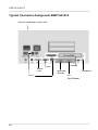
1
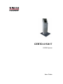
CERTO 415/417 KIOSK-System User Guide CERTO 415/417 Kiosk system User Guide November 2006 Linux™ is a registered trademark of Linus Torvalds Pentium™ is a registered trademark of the Intel Corporation MS-DOS™, Windows 98™, Windows NT™ and Windows CE™ are registered trade marks of the Microsoft Corporation BEETLE™ is a registered trademark of Wincor Nixdorf International GmbH The reproduction, transmission or use of this document or its con tents is not permitted without express authority. Offenders will be liable for damages. All rights, including rights created by patent grant or registration of a utility model or design, are reserved. Delivery subject to availability; technical modifications possible. Copyright © Wincor Nixdorf International GmbH, 2006 Contents Note on the laser 1 Laser safety ................................................................ 1 Device Overview 2 Device type ................................................................. 2 Components................................................................ 2 Device views 3 Front view ................................................................... 3 Rear view .................................................................... 4 Equipment carriage pulled out ...................................... 5 Front panel bottom removed......................................... 6 Basic operation 7 Opening/closing the device........................................... 7 Removing the front panel ........................................... 10 Installing the front panel ............................................. 11 Switch-on via power distributor ................................... 12 Switch-off via the power distributor.............................. 12 Measurements 13 Touchscreen 14 General..................................................................... 14 Capacitive Touch Screen ........................................... 14 How to Operate ....................................................... 15 Cleaning Instructions ................................................. 15 Technical Data Touchscreen 15’’ PanelLink .................................................................. 16 Technical Data Touchscreen 15’’ RGB ........................ 17 Technical Data Touchscreen 17’’ RGB ........................ 18 Printer TP07c 19 Functional components .............................................. 19 Printer control panel................................................... 20 Printer Connectors..................................................... 22 Changing the paper roll .............................................. 23 Setting the paper roll core diameter........................... 23 Choosing a paper roll holder .....................................24 Inserting the paper roll ..............................................25 Removing the paper roll............................................26 ERROR LED Blink Pattern..........................................27 Recoverable Errors ..................................................27 Unrecoverable Errors ...............................................28 Paper transport error ..................................................29 Cutter error ................................................................31 Error thermal print temperature, high voltage/low voltage .....................................................31 Technical Data...........................................................32 Consumables.............................................................33 Paper products ........................................................33 Paper specification...................................................33 Receipt roll dimensions.............................................33 Black mark print .........................................................34 Printing properties ....................................................34 Dimensions..............................................................34 Pre-printed receipts ..................................................35 Swipe Card Reader 37 Technical data ...........................................................37 DIP Reader ID24 38 Function elements......................................................38 Inserting an ID card....................................................39 Cleaning ....................................................................40 Hybrid DIP Reader 41 Functional elements ...................................................41 Inserting an ID card....................................................42 How the hybrid DIP reader works ................................42 Cleaning ....................................................................43 Typical integrated EFT device 44 Features ....................................................................44 Technical Data Hybrid Reader ....................................44 Technical Data PinPad .............................................45 BEETLE /M-II 46 Overview ...................................................................46 Back Panel of the BEETLE /M-II..................................48 Technical Data .......................................................... 49 Important notes ......................................................... 50 Embedded Compact PC 52 Overview of Compact PC ........................................... 52 Technical Data .......................................................... 52 Rear side .................................................................. 53 Barcode Reader 54 Technical Data .......................................................... 55 Keyboard 56 Technical Data .......................................................... 57 Door open sensor 58 Proximity Sensor/Camera 59 Proximity Sensor ....................................................... 59 Introduction ............................................................. 59 Function.................................................................. 59 Technical Data: ....................................................... 60 Camera..................................................................... 60 Features:................................................................. 60 Specification: ........................................................... 60 Approvals................................................................ 61 Appendix 62 Technical Data Certo 415/417 .................................... 62 Installation specifications.......................................... 62 Environmental Conditions......................................... 62 Power Cord Selection ................................................ 63 Block Diagram for CERTO 415 Kiosk System with P4 EPC.................................................. 64 Block Diagram for CERTO 417 Kiosk System with P4 EPC.................................................. 65 Typical Connector Assignment BEETLE/ M-II ............................................................ 66 CERTO 415/417 _____________________________________________________________________ Note on the laser If your device is equipped with a CD-ROM drive, the following condition applies: The CD ROM drive contains a light-emitting diode (LED), classified according to IEC 825-1:1993:LASER CLASS 1; it must not be opened. Laser safety The barcode scanner complies with safety standard EN60825-1 (2001) for a Class 1 laser product. It also complies with IEC 60825-1: 1993+A1:1997+A2:2001. Laser Radiation – do not stare directly into beam. Radiant Energy The barcode scanner uses a low-power laser diode operating at 650 nm in an opto-mechanical scanner resulting in less than 1.1 mW peak output power. _________________________________________________________ 1 CERTO 415/417 _____________________________________________________________________ Device Overview Device type CERTO 415/417 is a multifunctional information terminal designed for indoor installation. Components The CERTO 415/417 basic version consists of: - 15’’ or 17’’LCD monitor (w and w/o touch screen) System unit BEETLE /M-II or embedded PC Lock DOM Power distributor Stereo loudspeaker Country/project specific versions may comprise of the following optional components: - EFT terminal incl. PSU Barcode-scanner Thermal printer TP07c Proximity sensor Power supply system Open door switch Card reader Keyboard _________________________________________________________ 2 CERTO 415/417 _____________________________________________________________________ Device views Front view 1 2 3 4 6 5 7 8 1 2 3 4 5 6 7 8 Loudspeaker Proximity sensor /camera 15“ LCD-monitor with touch screen Barcode reader Integrated EFT terminal (PinPad + card reader) Lock of equipment carriage Paper output Front panel bottom _________________________________________________________ 3 CERTO 415/417 _____________________________________________________________________ Rear view 1 1 Opening for cable _________________________________________________________ 4 CERTO 415/417 _____________________________________________________________________ Equipment carriage pulled out Device with receipt printer TP07c 1 2 1 2 Receipt printer TP07c Power distributor (6 connectors shown in the picture, optional 3 connectors available) _________________________________________________________ 5 CERTO 415/417 _____________________________________________________________________ Front panel bottom removed 1 2 3 1 2 3 Power distributor (6 connectors shown in the picture, optional 3 connectors available) Fans System unit BEETLE /M-II _________________________________________________________ 6 CERTO 415/417 _____________________________________________________________________ Basic operation Opening/closing the device A set of two keys is supplied to open and to close the device doors (monitor cover, rear cover, equipment carriage). Pulling out the equipment carriage: Insert the supplied key into the lock and turn it in the direction of the arrow. _________________________________________________________ 7 CERTO 415/417 _____________________________________________________________________ Grasp the equipment carriage on both sides and pull it out of the device as far as possible (see arrows). Pushing in the equipment carriage: Push the equipment carriage into the device as far as possible. _________________________________________________________ 8 CERTO 415/417 _____________________________________________________________________ Turn the key in the direction indicated by the arrow and remove it from the lock. _________________________________________________________ 9 CERTO 415/417 _____________________________________________________________________ Removing the front panel Pull out the equipment carriage (see section "Pulling out the equipment carriage"). Grasping it on both sides, pull the front panel upwards to disengage the hooks (1). (1) (2) (1) (2) Pull the front panel a little forward (2) and set it down carefully in a protective place to avoid scratches. _________________________________________________________ 10 CERTO 415/417 _____________________________________________________________________ Installing the front panel Hang the catches of the front panel (1) over the fastening bolts on the sides (2) and push the front panel down as far as possible. 1 1 1 1 2 2 2 2 Push the equipment carriage in and lock it (see section "Pushing in the equipment carriage"). _________________________________________________________ 11 CERTO 415/417 _____________________________________________________________________ Switch-on via power distributor Pull out the equipment carriage (see section "Pulling out the equipment carriage"). Switch the device on by using the ON/OFF switch on the power distributor (see arrow). 3 connectors 6 connectors Switch-off via the power distributor Complete all current transactions and power the device down. Pull out the equipment carriage (see section "Pulling out the equipment carriage"). Switch off the device by using the ON/OFF switch at the power distributor (see arrow). 3 connectors 6 connectors _________________________________________________________ 12 CERTO 415/417 _____________________________________________________________________ Measurements Values in mm. Total height with baseplate 1552 mm. _________________________________________________________ 13 CERTO 415/417 _____________________________________________________________________ Touchscreen General The TFT LCD flat panel display is an XGA-compatible 15-inch flat panel display which is absolutely flicker free and low radiation. It is designed for a resolution of 1024 x 768 pixel. Application programs should be used with this resolution! The screen module represents the main unit of the BA73A-2. It comprises of a TFT-LCD colour screen, the TFT-interface and an inverter that generates the voltage for backlighting the screen. As an option the screens are available with Touch Screen including a beeper. Capacitive Touch Screen The TFT Touch Screen works according to the principle of a change in analogue capacitance. It has a glass screen with a transparent, thin-film overlay on the surface. This is fully sealed and protected by a further layer of clear glass. Electrodes on the edges of the screen provide an uniform low-voltage field. As soon as you touch the screen with your finger the contact point is “recognized” by the change in capacitance. Because this takes place very quickly, the Touch Screen is optimally equipped for a number of different requirements and applications. _________________________________________________________ 14 CERTO 415/417 _____________________________________________________________________ The programming interface of the screen is identical to the mouse interface. When you connect your new BA73A-2 to your BEETLE for the first time you have to calibrate the Touch Screen. Details depend on the operating system that you are using. How to Operate The Touch Screen responds to the slightest contact, therefore you do not have to apply much pressure when working with the screen. This does not only safe time, but is also kind to your joints! Touching the touch glass has the same effect as clicking the left mouse button. You only need to apply a little pressure with the fingertip. In this capacitive process only fingertip contact is recognized. The screen does not react in any way if touched, for example, with a pencil or a glove. Cleaning Instructions Always turn off the system before cleaning. The glass surface of your Touch Screen should be cleaned with a mild, abrasive free, commercially available glass cleaning product. All pH neutral materials (pH 6 to 8) are good for cleaning. Cleaners with pH values 9 to 10 are not recommended. Cleaning with water and isopropyl alcohol is possible as well. Do not use solvents containing acetic acid. Use a soft, fine-meshed cloth to clean the surface. Dampen the cloth slightly and then clean the screen. A wrong maintenance may cause damages to the screen, which are not covered by guarantee or warranty. _________________________________________________________ 15 CERTO 415/417 _____________________________________________________________________ Technical Data Touchscreen 15’’ PanelLink Frequencies Horizontal (KHz) 48,3 Vertical (Hz) 60 Resolution Horizontal 1024 pixel Vertical 768 pixel Colour depth: LCD adapter/ graphics PCI Controller: RGB 16, 256, 64k, LCD adapter: up to 16 mio. Pixel format approx. 0,30 mm x 0,30 mm Brightness min.: 200cd/m2 (center of LCD without glass) Interface LVDS Power supply 3,3 V from Interface Reading angle right/left top/button +/- 60° 45°/55° Backlight Twin lamps CCFL, Inverter, Lifetime: 50.000 h Current Consumption of the Screen Module Consisting of an LCD display, Touch Screen incl. controller, inverter, interface. 1 A + 12V (Normal Mode) 0 mA + 12V (Standby Mode) 1 A + 5V (Normal Mode) 400 mA + 5V (Standby Mode) _________________________________________________________ 16 CERTO 415/417 _____________________________________________________________________ Technical Data Touchscreen 15’’ RGB Frequencies Horizontal (KHz) 30 ~ 55 Vertical (Hz) 56 ~ 70 Resolution Horizontal 1024 pixel Vertical 768 pixel Colour depth: 8-bit, 16 million Pixel format 0.297 mm x 0.297 mm Brightness 260cd/m2 Interface RGB analog Power supply 12VDC, 3A (max) Reading angle right/left top/button +/- 60° 45°/55° Backlight Twin lamps CCFL Lifetime: 50.000 h Current Consumption 18 W + 12V (Normal Mode) 1.5W + 12V (Standby Mode) _________________________________________________________ 17 CERTO 415/417 _____________________________________________________________________ Technical Data Touchscreen 17’’ RGB LCD Display 17" TFT Active Matrix Panel Brightness 300 cd/m2 (typ.) Pixel Pitch (mm) 0.264(H) x 0.264(V) Max. Resolution 1280x1024 (SXGA) Contrast Ratio 500:1 (typ.) Display Area 337.92 x 270.336mm Response Time (Typ.) 8ms (typ.) Support Color 16.2 M Viewing Angle +70°~-70° (H), +70°~-70° (V) (typ.) Nominal Input Voltage VDD +5.0V (typ.) Power Comsumption 25.8W (typ.) Electrical Interface Dual Channel LVDS Surface Treatment Anti-glare, Hard Coating (3H) Inverter LI0419B A/D Board AD5621 Option Touch Screen _________________________________________________________ 18 CERTO 415/417 _____________________________________________________________________ Printer TP07c Functional components 1 1 2 3 4 5 6 7 2 3 4 5 6 7 Receipt output (presenter) Cutter Paper core adjustment Thermal print module Paper roll holder Printer control panel Paper guide _________________________________________________________ 19 CERTO 415/417 _____________________________________________________________________ Printer control panel 1 2 3 4 5 1 TEST-button 2 LED ERROR 3 LED PE (paper end) 4 LED POWER 5 LINE FEED-button _________________________________________________________ 20 CERTO 415/417 _____________________________________________________________________ 1 TEST button 2 LED ERROR red For test printout. Off: normal condition On: offline Blinking: error (see section „ERROR LED Blink Pattern“) 3 LED PE (paper end) yellow Off: paper is loaded On: paper roll near end is detected Blinking: paper roll end is detected 4 LED POWER green Off: power is not stable On: power is stable 5 LINE FEED button When the button is pressed once, the paper feeds 1/6". When the button is pressed longer than two seconds, the paper is fed constantly until the button is released. _________________________________________________________ 21 CERTO 415/417 _____________________________________________________________________ Printer Connectors 1 1 Power supply connector 2 Printer controller 3 USB (Full Speed) 2 3 for power supply connection with 24V For system connection _________________________________________________________ 22 CERTO 415/417 _____________________________________________________________________ Changing the paper roll Note the following when changing a paper roll. Setting the paper roll core diameter When starting the device or when changing the paper roll diameter check whether the selection switch for the paper near end adjustment is set to the correct position. Core diameter 18 mm 25 mm 40 mm Paper roll diameter 180 mm Pos. A1 Pos. A2 Pos. A3 A AAA 3 21 _________________________________________________________ 23 CERTO 415/417 _____________________________________________________________________ Choosing a paper roll holder Choose the roll holder which fits to the paper roll core Holder for 18 mm core diameter (identifier 1) Holder for 25 mm core diameter (identifier 2) Holder for 40 mm core diameter (identifier 3) _________________________________________________________ 24 CERTO 415/417 _____________________________________________________________________ Inserting the paper roll Push the paper roll holder into the paper roll core. Insert the paper from behind into the printer as shown in the illustration. Mind the unrolling direction of the paper. Insert the black mark sensor (top left, top right, bottom left, bottom right) when using paper with black marks. For correct paper feed or paper transport the front edge of the paper has to be straight and at right angles. We, therefore, recommend to cut the paper with scissors. _________________________________________________________ 25 CERTO 415/417 _____________________________________________________________________ Take the front edge of the paper over the upper axle and feed it into the paper support (see arrow). Keep pushing the paper into the paper support until it is retracted automatically, the paper is cut off and the printed receipt is output via the presenter. . See also the sticker on the printer. Remove the receipt that was cut off before. Removing the paper roll Cut off the paper at the paper support. Lift the paper roll out of the printer with the paper roll holder upwards. Use the LINE FEED button to remove the remaining paper. _________________________________________________________ 26 CERTO 415/417 _____________________________________________________________________ ERROR LED Blink Pattern Recoverable Errors The following table shows the blink pattern of all errors, that can be recovered by following the steps described in section “Paper feed error”. LED OFF LED ON Error Description Paper jam while cutting The automatic cutter doesnot work because it does not leave or does not reach the home position. A paper jam is detected between print starting position and TOF sensor. The printer does not find the Black Mark. Paper jam before cutting Black Mark detecting error Paper jam after cutting – in presenter ERROR LED Blinking Pattern 1 Approximately 5sec 3 Approximately 5sec 4 5 A paper jam is detected after the printer cuts the paper. This occurs in the printers’ presenter. Approximately 5sec Approximately 5sec _________________________________________________________ 27 CERTO 415/417 _____________________________________________________________________ The following errors can be recovered by removing and inserting the paper roll Error Description ERROR LED Blinking Pattern TOF position not found Operation after power on error StartOfJob timeout After cutting the printer does not find the TOF position. Paper is after power on not at the print starting position. This error is enabled by memory switch 7-4. StartOfJob timeout occurred because no EndOfJob was received within the specified time. 7 Approximately 5sec 8 Approximately 5sec Approximately 5sec Unrecoverable Errors Error Description Temperature There is an error thermal abnormality print head of the print line temperature High voltage The power error supply voltage is extremely high. Low voltage The power error supply voltage is extremely low. ERROR LED Blinking Pattern 1 Approximately 5sec 3 Approximately 5sec 4 Approximately 5sec For recovery please contact the Technical Services. _________________________________________________________ 28 CERTO 415/417 _____________________________________________________________________ Paper transport error In case of a paper jam open the presenter by releasing the stop lever (Take out the presenter, see illustration). Check the paper transport path and remove the paper scraps, if necessary. _________________________________________________________ 29 CERTO 415/417 _____________________________________________________________________ Check whether the cutter is in home position. If it is not, use the thumb wheel as long as you can see the auburn plastic part on top of the cutter. Check the print area of the thermal head for paper scraps. Use the green lever and flap the printing unit upwards. _________________________________________________________ 30 CERTO 415/417 _____________________________________________________________________ Cut off the remaining paper at the paper support and pull it out. Check if the paper roll is inserted correctly or a paper roll without black mark is inserted. Reinsert the paper (see section "Inserting the paper roll"). Cutter error Check whether the cutter is in home position. If it is not, use the thumb wheel as long as you can see the auburn plastic part on top of the cutter. Unplug the power plug and plug it again. This should initialize the printer. If this does not help, please contact the Technical Service. Error thermal print temperature, high voltage/low voltage Please contact the Technical Services _________________________________________________________ 31 CERTO 415/417 _____________________________________________________________________ Technical Data Technology Graphic Print speed Character pitch Character per line Line pitch Print attributes Code pages Interface Power supply Sensors Thermal receipt printer 203 x 203 dpi (8 dots/mm) up to 150 mm/sec 10.2 / 12.7 / 14.5 / 16.9 / 20.3 cpi 28 char/line 10.2 cpi 36 char/line 12.7 cpi 41 char/line 14.5 cpi 48 char/line 16.9 cpi 57 char/line 20.3 cpi 6 and 8 lines/inch additional micro steps n/203 inch - inverse - underline - bold - upside down - turn (90° steps) - n-times heights (1-8) - n-times width (1-8) - 437 (IBM set II) - 850 (Multilingual) - 852 (Latin II9) - 858 (Latin II, EURO Symbol) - 860 (Portuguese) - 863 (Canadian French) - 865 (Nordic) - 866 (Cyrillic) - 1252 (Windows and loadable) USB (Full speed) 24V - Paper near end - Paper end - Top of Form - TOF mark - Presenter out - Cutter _________________________________________________________ 32 CERTO 415/417 _____________________________________________________________________ Consumables Paper products Please refer to the following paper specifications for details on the paper quality. Paper specification Paper quality Paper type Paper color Paper thickness Paper smoothness (print side ) OJI KF50 – HDA or equivalent Thermal paper on rolls (thermal layer on the outside) white min 0.06 – max 0.1 mm min. 300 Bekk Sec. Receipt roll dimensions Paper width Paper weight Outer receipts roll diameter max. End of Paper Inner diameter of roll sleeve Paper core wall thickness Paper core material 80 mm (- 1mm) 55g/m2 – 80g/m2 180mm not glued to roll core 18 mm, 25 mm or 40 mm (+ 1 mm) 2mm (+ 1mm) cardboard/ plastic _________________________________________________________ 33 CERTO 415/417 _____________________________________________________________________ Black mark print Printing properties Opacity PCS value control mark Position Reflection factor Ro 85 % according to DIN 53 146 70 % according to DIN 66 223 left or right or both on the same height 70 % according to DIN 53 145 part 1 Mark height Mark width Mark color Black mark distance 5 mm 0,1 mm 8 mm 0,1 mm black, uncoloured black min. 70 mm, max. 210 mm Dimensions Front side all dimensions in the drawings in mm Min. 70mm/max. 210mm 5 8 Feeding direction _________________________________________________________ 34 CERTO 415/417 _____________________________________________________________________ Rear side 5 18 Feeding direction Pre-printed receipts The receipts can be pre-printed on the front and on the back side in the hatched area (see illustration). In case of pre-printing outside the specified area the PCS value must be lower than 40%, and no sensor-sensitive colors should be used. The sensor light should be reflected completely by pre-printed colors. Front side 8,5 Feeding direction 8,5 _________________________________________________________ 35 CERTO 415/417 _____________________________________________________________________ Rear side 5 18 Feeding direction _________________________________________________________ 36 CERTO 415/417 _____________________________________________________________________ Swipe Card Reader The magnetic card reader can read three ISO tracks simultaneously per card swipe. The card tracks can only be evaluated if the card is swiped manually. The card must be swiped through the slot from top to bottom at a swift, even pace. The swipe card reader is always connected via the BA72 MSR controller. Technical data Card standards Magnetic card coding Speed of card movement DC power supply Current consumption Weight approx. Dimensions ISO 7811, ANSI, AAMVA, CA DMV acc. to ISO 7811 10 cm/s to 140 cm/s +5V 1.0 / 1.25 mA 60 g 100 x 25 x 25 mm _________________________________________________________ 37 CERTO 415/417 _____________________________________________________________________ DIP Reader ID24 The DIP reader ID24 reads the data on an ID card's magnetic stripe when the card is inserted. Function elements The DIP reader ID24 can be installed in the device in such a way that the magnetic track of the ID card faces either up or down. The following picture shows the installation position 'track up'. 1 Read head (behind the panel) 2 Card insertion slot _________________________________________________________ 38 CERTO 415/417 _____________________________________________________________________ Inserting an ID card When you insert an ID card, you should make sure that the magnetic stripe is in the correct position. The ID card unit cannot read the ID card information correctly, unless you insert the ID card into the ID card unit as described below. The insertion of the ID card depends on the installation position of the card reader. The ID card can be inserted in the following ways: Installation position: track facing up Insert the ID card into the ID card unit as shown in the picture. Installation position: track facing down Insert the ID card into the ID card unit as shown in the picture. _________________________________________________________ 39 CERTO 415/417 _____________________________________________________________________ Cleaning The DIP reader ID24 is cleaned with a cleaning card. Check that no dirt remains in the card insertion slot. (If necessary, clean the card insertion slot with a brush.) You can clean the read head when the device is switched on or off. Cleaning interval: every 20,000 transactions Cleaning material: Wincor Nixdorf ELIX wet cleaning card Order number:01750016388 Cleaning process • • • • • Remove the cleaning card from its packaging. The cleaning card can only be used for a brief period as it is a presaturated cleaning card which dries out after removal from its packaging. Insert the cleaning card into the card insertion slot like a regular ID card. Pull the cleaning card from the slot. Repeat this a few times. Dispose of the cleaning card. _________________________________________________________ 40 CERTO 415/417 _____________________________________________________________________ Hybrid DIP Reader The hybrid DIP reader reads the data on an ID card's magnetic stripe when the card is inserted. When the card is inserted the chip data can be processed. Functional elements 1 LED 2 Card insertion slot _________________________________________________________ 41 CERTO 415/417 _____________________________________________________________________ Inserting an ID card When you insert an ID card, you should make sure that the magnetic stripe is in the correct position. The ID card unit cannot read the ID card information correctly, unless you insert the ID card into the ID card unit as described below. Insert the ID card into the ID card unit as shown in the picture. How the hybrid DIP reader works Depending on the application software, the magnetic tracks are read either when the ID card is inserted or when it is pulled out (reading on insertion is the standard). Therefore, it is important that the ID card is pushed in and pulled out in one smooth motion. If the chip card function is used, the card is automatically locked in the insertion slot and released after processing is completed. The meaning of the LED indicator above the card insertion slot is defined via the application software. Therefore it cannot be described in this manual. The module is designed in such a way that inserted foreign bodies (coins, for example) can fall directly through the insertion slot to the bottom of the device. _________________________________________________________ 42 CERTO 415/417 _____________________________________________________________________ Cleaning The hybrid DIP reader is cleaned with a cleaning card. Check that no dirt remains in the card insertion slot. (If necessary, clean the card insertion slot with a brush.) You can clean the read head when the device is switched on or off. Cleaning interval: every 20,000 transactions Cleaning material: Wincor Nixdorf ELIX wet cleaning card Cleaning process • Remove the cleaning card from its packaging. The cleaning card can only be used for a brief period as it is a presaturated cleaning card which dries out after removal from its packaging. • Insert the cleaning card into the card insertion slot like a regular ID card. • Pull the cleaning card from the slot. • Repeat this a few times. • Dispose of the cleaning card. _________________________________________________________ 43 CERTO 415/417 _____________________________________________________________________ Typical integrated EFT device Features - Multi application - Open Java based architecture - Leading edge security - Customer and solution oriented - EMV & Visa PED approved Technical Data Hybrid Reader Chip-card reader ID1 Interface Integrated smart card reader ISO 7816 Parts 1,2,3 Tracks are read either when the ID card is inserted or when it is pulled ISO 7810, ISO 7811 1,2 ,3,4,5 Tracks are read either when the ID card is inserted or when it is pulled 500 000 operations (clean indoor environment) 2x13pin parallel interface Power supply via power supply unit Magnetic stripe reader Card reader lifetime _________________________________________________________ 44 CERTO 415/417 _____________________________________________________________________ Technical Data PinPad Approvals Interface Keyboard Display Electrical supply Lithium backup battery Microcontroller und memory ZKA, PCI–PED, CE 1 x Power 1 x Serial RS232 1 x Parallel to open frame Hybrid Card Reader 1 slot for SAM (ID000 format) 16 – keys anti vandal stainless steel keyboard Keyboard lifetime: 2 million operations Numeric key size: 14 mm x 14 mm Command key size: 28 mm x 14 mm For the assistance of the visually impaired, the keyboard is marked with a tactile dot on the „5” key and tactile symbols on the cancel (X), clear (<) and enter (O) keys. 132 x 40 dot backlit graphics display 7 x 5 dot character size, heights 3,8 mm Scratch-resistant glass face 4mm thickness Display lifetime: 70 000 hours Vin 10-24 V DC Typ CR1/2AA, Expected lifetime 7 years 32-Bit RISC Processor Memory: 2 MB Flash, 512KB SRAM _________________________________________________________ 45 CERTO 415/417 _____________________________________________________________________ BEETLE /M-II Overview The following figure shows the outside of the BEETLE /M-II. On/Off Button LEDs USB DVD/CD-ROM drive (optional) _________________________________________________________ 46 CERTO 415/417 _____________________________________________________________________ The figure below shows the interior of the BEETLE /M-II. Carrier for DVD/ CD ROM Drive Hard Disk Power supply unit Ventilators for processor Intrusion sensor (optional) _________________________________________________________ 47 CERTO 415/417 _____________________________________________________________________ Back Panel of the BEETLE /M-II The figure shows the back panel of the BEETLE /M-II (E1 CPU) with the locations of the connecting sockets and connecting plugs. If you wish to connect a monitor, however, you must also have a video board. You can connect the system to a network via an expansion board. ► Connecting peripherals with the system switched on is not allowed, except for USB. _________________________________________________________ 48 CERTO 415/417 _____________________________________________________________________ Technical Data BEETLE /M-II Motherboard E1 CPU Chip set Intel 845GV Microprocessor Intel P4, 2.2 GHz Celeron, 2.4 GHz HDD IDE HDD 40 GB/80 GB RAM 256 MB – 2GB, 2 DIMM plug (184pin) 2.5V DDR SDRAM technology, unbuffered non EEC DDR266, standard DIMM, height up to 35mm LAN 1x On-board Intel LAN module Interfaces 1 x RS232 COM port 3 x Powered COM port 3 x USB 2.0 port, 2USB rear- 1USB front- other interface options possible via adapter boards 1 x DVI port, depending on configuration 1 x VGA port, depending on configuration 1 x keyboa rd, AT compatible 1 x mouse, via Y cable together with keyboard optional internal connection 1 x speaker port 1 x LAN port 1 x cash drawer 1 x parallel interface IEEE 1284 compatible (ECP, EPP, PS/2 – compatible) Output Power +12V DC +5V DC Sub Modules LAN controller or an ASYNC Connection (optional) ; CRT adapter or a CRT adapter _________________________________________________________ 49 CERTO 415/417 _____________________________________________________________________ Important notes The modular POS system BEETLE /M-II conforms to the current safety standards for data processing equipment. If this device is taken from a cold environment into the operating room, moisture condensation may form. The device must be absolutely dry before being put into service; an acclimatization period of at least two hours must therefore be observed. This device is equipped with a safety-tested power cable and may be connected only to a prescribed grounded-contact power socket. When setting up the device, ensure that the power socket on the device and the grounded-contact power socket are easily accessible. To disconnect the device from the supply voltage completely, switch off the device und disconnect the power plug. Ensure that no foreign objects (e.g. office clips) find their way into the device, as this may lead to electric shocks or short-circuits. In order to ensure that the device is well ventilated and to prevent overheating, do not obstruct the ventilation slots on your device. Never plug in or unplug data communication lines during thunderstorms. Protect devices from vibrations, dust, moisture and heat. Always dispose of used parts in an environmentally safe manner. The lithium battery must be replaced by the end user only by identical batteries or types recommended by Wincor Nixdorf International GmbH. The lithium battery must be disposed of in accordance with local regulations for special waste. _________________________________________________________ 50 CERTO 415/417 _____________________________________________________________________ In emergencies (e.g. damaged housing or damaged power cable, penetration by liquids or foreign bodies), the device must be switched off immediately, the power plug disconnected and the Customer Service of Wincor Nixdorf International GmbH or your dealer must be notified. Your BEETLE system is the result of modern technical innovation. So please see for according structural and technical surroundings to guarantee a faultless and efficient work of your BEETLE. Therefore, you should connect your BEETLE or other IT-devices only to power supply systems with separately guided protective earth conductor (PE). This kind of electricity system is known as TN-S network. Do not use electricity systems with PEN conductors! Please also observe the recommendations of the norm DIN VDE 0100, Part 540, Appendix C2 as well as EN50174-2, §5.4.3. Thus you can help to avoid possible malfunctions. The device may only be repaired by authorized qualified personnel. Unauthorized opening of the device and inexpertly carried-out repairs may not only seriously jeopardize the safety of the user, but also cancel all warranty and liability agreements. _________________________________________________________ 51 CERTO 415/417 _____________________________________________________________________ Embedded Compact PC Overview of Compact PC The device is equipped with a Celeron 4 Embedded Compact PC. Technical Data Motherboard P195-Plus Motherboard Chip set Intel 845GV Microprocessor Intel Pentium 2.0 GHz (PGA478) HDD IDE HDD 40 GB RAM DDR 512 MB LAN 1x On-board Intel LAN module Interfaces 2 x RS232 COM port 4 x Powered COM port 6 x USB 2.0 port 1 x DVI port 1 x VGA port 1 x keyboard 1 x mouse 1 x speaker port 1 x LAN port Output Power +12V DC +5V DC Add On Cards SUNIX PCI Multi I/O Card _________________________________________________________ 52 CERTO 415/417 _____________________________________________________________________ Rear side 10/100 LAN Audio ports Sunix PCI COM 4-port 12VDC output USB 1/2 COM1 PS/2 keyboard VGA COM5 COM6 COM2 USB 3/4 DVI MIDI USB 5/6 _________________________________________________________ 53 CERTO 415/417 _____________________________________________________________________ Barcode Reader The omnidirectional scan pattern offers outstanding scan performance on all standard 1D bar code symbologies, including RSS. The scanner’s main cable connector is located at the top of the unit to facilitate mounting and the auxiliary connector gives users access to several of the I/O signals, providing the flexibility for external hookup of beepers, buttons, and LED’s. The barcode reader is equipped with powerful features such as easy programming, user replaceable cables and upgradeable software. _________________________________________________________ 54 CERTO 415/417 _____________________________________________________________________ Technical Data Light Source Laser Power Decode Capability Visible Laser Diode 650 nm 1.1 mW (peak) Autodiscriminates all standard 1D bar codes, including RSS-Expanded,RSS-14 and RSS-14 Limited; System Interfaces RS232, Light Pen Emulation, Keyboard Wedge, Stand Alone Keyboard, IBM 468x/469x, USB, Laser Emulation, OCIA Number Characters Read Up to 80 data characters Beeper Operation 7 tones or no beep Indicators Blue = laser on, ready to scan White = good read Input Voltage 5 VDC + 0.25 V Power 1.375 W Operating Current 275 mA typical @ 5 VDC DC Transformers Class 2; 5.2 VDC @ 650 mA Laser Class Class 1; IEC60825-1:1993/A1:1997+A2:2001 Class 1; EN60825-1:1994/A11:1996+A2:2001 EMC FCC, ICES-003 & EN55022 Class B Depth of Scan Field 25 mm - 279 mm (1” - 11”) for 0.33 mm (13 mil) bar code(programmable) at default setting Width of Scan Field 30 mm (1.2”) @ 25 mm (1.0”); 150 mm (5.9”) @ 280 mm (11.0”) Scan Speed 1650 scan lines /sec, omnidirectional; 80 scan lines /sec,single line Scan Pattern 5 fields of 4 parallel lines omnidirectional; or button activated single line Number of Scan Lines 20 (omnidirectional); or 1 (single-line) Minimum Bar Width 0.127 mm (5.0 mil) Print Contrast 35% minimum reflectance difference Roll, Pitch, Yaw 360°, 60°, 60° _________________________________________________________ 55 CERTO 415/417 _____________________________________________________________________ Keyboard Advantages / Highlights: – Prestigious design – Especially designed for kiosk and public environment – Vandal resistant – sealed to IP65 / NEMA4 – Fireproofed ABS Layer for best tactile keystrokes – Keycaps with trough for better typing comfort – Keycaps made of stainless steel, non removable, fireproof – Full travel keys with 2.2 mm stroke – Best tactile feel via silicone mat – Laser engraved legends (customized optional) – Any language via programmable controller – Connectivity via USB – Keyboard front panel made of 4 mm stainless steel – Standard or custom front plate design (optional) – Back panel version – Robustly & longevity 38 mm plastic trackball – Stainless-Steel-Trackball (optional) – Integrated USB-HUB (2port) to connect keyboard & trackball _________________________________________________________ 56 CERTO 415/417 _____________________________________________________________________ Technical Data Dimension: Number of Keys: Key Technology: Key Strokes: Durability: Sealing: Connectivity: Connector: Material Front panel: Trackball Diameter: Ball Material: Transducers: Number of Keys: Key Strokes: Sealing: Connectivity: Connector: 403.5 x 137.9 x 32 mm 70 Membrane switch 0.7N / 2.2mm / Tactile feel 10 million Operations P65 USB USB A - A Stainless Steel 4mm 38 mm Plastic / Stainless-Steel optional Photo-optical encoders 2 3N / 0.4mm / Tactile feel IP65 (static) / shock proofed USB Mini USB – USB A _________________________________________________________ 57 CERTO 415/417 _____________________________________________________________________ Door open sensor The sensor is located behind the equipment carriage. If the carriage is pulled out of the device a signal is send to the application software for further reactions. _________________________________________________________ 58 CERTO 415/417 _____________________________________________________________________ Proximity Sensor/Camera Proximity Sensor Introduction The proximity sensor is predominantly applied in self-service terminals such as e. g. kiosk terminals or ticket automats. Persons and objects of comparable size who approach the kiosk terminal are detected by the sensor and are signalled to the application program via evaluation electronics. The application can react to this message e. g. by sending out acoustic signals or by changing the content on the monitor, as soon as a customer approaches the automat. Function On radar sensor basis persons as well as objects of comparable size, who move within the detection area of the sensor, are detected. The signal of the sensor is extended by means of auxiliary electronics; i. e. the signal backspaces 15 seconds after the last detected movement. In case of detection of a further movement within this time frame the delay time will be restarted. _________________________________________________________ 59 CERTO 415/417 _____________________________________________________________________ Important: The sensor does only react on movement. A person standing in front of the terminal without moving will not be detected. It is thus not possible to tell by means of the output signal of the sensor, if a person is present in front of the terminal or not. The sensor can be protected from vandalism by being implemented directly behind plastic covers. It can either be implemented behind an opening of at least 35 x 45 mm in metallic cabinet, whereas the opening in turn can be covered by a plastic element. Starting from the sensor surface the sensitivity area is ball-shaped. Technical Data: Supply voltage: Current consumption: Sensitivity distance: 24V DC +- 10% ca. 50mA pre-adjusted to ca. 1m Camera Features: Low cost and high quality VGA 640x480 @ 30 frame rate per second USB Interface with Plug and Play Lens focus from 3 cm to infinity Full screen 640 x 480 display High quality lens for sharp pictures High-quality still pictures and motion video capturing Specification: Sensor: CMOS 120K pixels (image up to 640x480) Video format: 24-Bit True Color USB interface: compliant to USB 2.0 and 1.1 Image res: 640x480, 352x288, 320x240, 176x144, 160x120 Video resolutions: 640x480, 352x288, 320x240, 176x144, 160x120 VGA 640x480 @ 30 frame rate per second Adjustable focus: 3 CM to infinity Automatic white balance _________________________________________________________ 60 CERTO 415/417 _____________________________________________________________________ Automatic exposure Automatic compensation Store digital videos in AVI and WMV file formats Store digital photos in JPEG and BMP file formats Approvals CE, FCC _________________________________________________________ 61 CERTO 415/417 _____________________________________________________________________ Appendix Technical Data Certo 415/417 Installation specifications CERTO 415/417 Kiosk System With base plate Without base plate Dimensions: Height: Depth: Width: 1552 mm 268 mm 472 mm 1542 mm 268 mm 472 mm Weight of device: Approx. 96 kg Approx. 81 kg Environmental Conditions Operating Indoor air conditioned environment +10°C to +30°C, Optimum operating range (+5°C to +32°C: In this temperature range the system must only be operated for a short period of time) Relative Humidity: +10% to 75% RH, non-condensing Storage Temperature: +10°C to +85°C Relative Humidity: 5% to 85% RH, non-condensing Power supply 100-120V AC @ 50/60Hz 200–240V AC @ 50/60Hz Power consumption 4A 2A _________________________________________________________ 62 CERTO 415/417 _____________________________________________________________________ Power Cord Selection If the power cord is not provided with the system, the user has to ensure that a certified power cord is used as required by the Safety Regulation of the country. Countries Safety Approvals USA UL Canada CSA Germany GS Japan PSE Taiwan BSMI China CCC For other countries not mentioned in the above list, please check with the local authority. _________________________________________________________ 63 CERTO 415/417 _____________________________________________________________________ Block Diagram for CERTO 415 Kiosk System with P4 EPC (Sample) 15” LCD with Touch DC 12 V Chassis Lock Keyboard and Mousepad USB4 USB5 COM1 VGA AC Power USB2 COM3 COM5 Sunix PCI COM Card External USB1 USB3 USB6 PS/2 SPK COM4 COM6 Barcode Scanner Printer Swipe Card Reader 24V DC 8 Oh m Speaker Powe r Lines Data Lines _________________________________________________________ 64 CERTO 415/417 _____________________________________________________________________ Block Diagram for CERTO 417 Kiosk System with P4 EPC (Sample) 17” LCD with Touch DC 12 V Chassis Lock Keyboard and Mousepad USB4 USB5 COM1 VGA AC Power USB2 COM3 COM5 Sunix PCI COM Card External USB1 USB3 USB6 PS/2 SPK COM4 COM6 Barcode Scanner Printer Swipe Card Reader 24V DC 8 Oh m Speaker Powe r Lines Data Lines _________________________________________________________ 65 CERTO 415/417 _____________________________________________________________________ Typical Connector Assignment BEETLE/ M-II Service Keyboard at front USB PLink/RGB Display Touch Waiter Lock TP07c Speakers Barcode Reader EFT/ Card Reader _________________________________________________________ 66 Published by Wincor Nixdorf International GmbH D-33094 Paderborn Order Number: 01750124050A