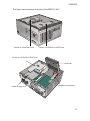
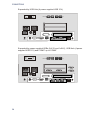
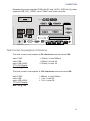
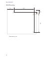
1
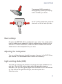
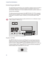
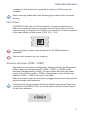
BEETLE /M-II Modular POS System User Guide Edition April 2010 Linux™ is a registered trademark of Linus Torvalds Pentium™ is a registered trademark of the Intel Corporation MS-DOS™, Windows 95™, Windows 98™, Windows NT™, Windows ME™, Windows2000™and Windows XP™ are registered trademarks of the Microsoft Corporation BEETLE™ is a registered trademark of Wincor Nixdorf International GmbH Copyright© Wincor Nixdorf International GmbH, 2010 The reproduction, transmission or use of this document or its contents is not permitted without express authority. Offenders will be liable for damages. All rights, including rights created by patent grant or registration of a utility model or design, are reserved. Delivery subject to availability; technical modifications possible. Contents Manufacturer´s Certification...............................................1 Tested Safety..............................................................................................1 FCC-Class A Declaration............................................................................1 Note on the laser ........................................................................................2 Important notes ...........................................................................................2 Introduction..........................................................................4 About this manual .......................................................................................5 Care of the BEETLE /M-II ...........................................................................5 Recycling the BEETLE /M-II .......................................................................6 Warranty .....................................................................................................7 BEETLE /M-II- the individual POS System.........................8 Overview.....................................................................................................8 BEETLE /M-II Peripherals .....................................................................9 BEETLE /M-II in a network ..................................................................10 Before switching on the System................................................................11 Unpacking and checking the System ..................................................11 Setting up the device...........................................................................12 Vertical installation of the equipment...................................................12 Cabling of the BEETLE /M-II.....................................................................14 Securing the data cable ............................................................................15 Mounting the cable cover ..........................................................................16 Connecting to the mains power supply .....................................................17 Disconnecting cables ................................................................................18 Basic settings............................................................................................19 Adjusting the loudspeaker.........................................................................19 Light emitting diode (LED) ........................................................................19 Connecting peripherals .............................................................................20 Keyboard (KYBD)................................................................................20 Cash drawer .......................................................................................21 Scanners and scales (COM1 - COM4*) ..............................................21 Customer display (COM2* or COM4*).................................................22 Cashier display (COM3*).....................................................................22 Monitor ...............................................................................................22 TFT - LCD Display ..............................................................................23 Connecting standard PC peripherals (COM1) .....................................23 Network ...............................................................................................24 Modular printers .................................................................................24 USB (Universal Serial Bus) .................................................................24 BEETLE /M-II- the Components........................................26 Overview...................................................................................................26 CD/DVD Drive (Optional) ..........................................................................28 General ...............................................................................................28 Operating the Drive .............................................................................28 Notes...................................................................................................29 Power pack ...............................................................................................29 Battery (optional).......................................................................................30 Security in the Event of a Power Outage.............................................30 Mounting the Battery ...........................................................................31 uDiskOnChip (Option)...............................................................................33 Changing a uDiskOnChip (uDOC).......................................................33 Replacing the 3,5 hard disk (SATA)..........................................................36 Configuration variants ......................................................38 Submodules for the CPU ..........................................................................38 CRT- or TFT-adapter ..........................................................................38 Installing the submodules and adapters....................................................39 PCI Cards .................................................................................................41 Installing an expansion card......................................................................41 Starting up the system ......................................................44 Appendix ............................................................................46 Technical data for the BEETLE /M-II ........................................................46 Interfaces ..................................................................................................47 Connections ..............................................................................................48 Standard..............................................................................................48 Options................................................................................................48 Total Current Consumption of Interfaces.............................................51 Wall Mounting ...........................................................................................52 Glossary....................................................................................................53 Abbreviations ............................................................................................55 TESTED SAFETY Manufacturer´s Certification The device complies with the requirements of the EEC directive 89/336/EEC with regard to ‘Electromagnetic compatibility" and 73/23/EEC “Low Voltage Directive”. Therefore, you will find the CE mark on the device or packaging. Tested Safety The POS system has been provided with the symbol for “Tested Safety”. In addition, the BEETLE has received the UL symbol and cUL symbol. FCC-Class A Declaration This equipment has been tested and found to comply with the limits for a Class A digital device, pursuant to part 15 of the FCC Rules. These limits are designed to provide reasonable protection against harmful inter-ference when the equipment is operated in a commercial environment. This equipment generates, uses, and can radiate radio frequency energy and, if not installed and used in accordance with the instruction manual, may cause harmful interference to radio communications. Operation of this equipment in a residential area is likely to cause harmful interference in which case the user will be required to correct the interference at his own expense. Modifications not authorized by the manufacturer may void users authority to operate this device. This class A digital apparatus complies with Canadian ICES-003. Cet appareil numerique de la classe A est conforme à la norme NMB-003 du Canada. 1 IMPORTANT NOTES Note on the laser lf your device is equipped with a DVD drive, the following condition applies: The DVD drive contains a light-emitting diode (LED), classified according to IEC 825-1:1993:LASER CLASS 1; it must not be opened. Important notes The modular POS system BEETLE /M-II conforms to the current safety standards for data processing equipment. 2 n If this device is taken from a cold environment into the operating room, moisture condensation may form. The device must be absolutely dry before being put into service; an acclimatization period of at least two hours must therefore be observed. n This device is equipped with a safety-tested power cable and may be connected only to a prescribed grounded-contact power socket. n When setting up the device, ensure that the power socket on the device and the grounded-contact power socket are easily accessible. n To disconnect the device from the supply voltage completely, switch off the device and disconnect the power plug. n Ensure that no foreign objects (e.g. office clips) find their way into the device, as this may lead to electric shocks or short-circuits. n Never plug in or unplug data communication lines during thunderstorms. n Protect devices from vibrations, dust, moisture and heat. n Always dispose of used parts, such as batteries, in an environmentally safe manner. n The lateral ventilation slots of the BEETLE /M-II must remain unobstructed to ensure sufficient ventilation of the equipment. If the equipment is to be fitted, you must ensure that the specified minimum distances are maintained and constant ventilation is provided. IMPORTANT NOTES n In emergencies (e.g. damaged housing or damaged power cable, penetration by liquids or foreign bodies), the device must be switched off immediately, the power plug disconnected and the Customer Service of Wincor Nixdorf or your dealer must be notified. n The lithium battery must be disposed of in accordance with local regulations for special waste. In case of an improper change of the lithium battery it exist an explosion risk. n The device may only be repaired by authorized qualified personnel. Unauthorized opening of the device and inexpertly carried-out repairs may not only seriously jeopardize the safety of the user, but also cancel all warranty and liability agreements. n Your BEETLE system is the result of modern technical innovation. So please see for according structural and technical surroundings to guarantee a faultless and efficient work of your BEETLE. Therefore, you should connect your BEETLE or other IT-devices only to power supply systems with separately guided protective earth conductor (PE). This kind of electricity system is known as TN-S network. Do not use PEN conductors! Please also observe the recommendations of the norm DIN VDE 0100, Part 540, Appendix C2 as well as EN50174-2, §5.4.3.Thus you can help to avoid possible malfunctions. 3 INTRODUCTION Introduction The BEETLE /M-II is the compact, powerful and economical basis for your POS system. The BEETLE /M-II conforms to the PC/AT industry standard. Powerful Pentium- M/Celeron- M processors ensure a quick processing of all operations. You can connect a variety of different peripheral devices to your BEETLE /M-II and even the choice of the software is not limited to a certain product. Optional the BEETLE /M-II can be equipped with a DVD drive. This provides you with a considerable degree of flexibility when arranging the configuration of your POS system. The BEETLE can also be connected to a network once an appropriate network card has been installed. In the event of a mains voltage failure, the version with battery and corresponding software enable you to save the data by means of a controlled program shutdown. Whatever configuration you need: Wincor Nixdorf International GmbH offers the right solution. So, whenever you want to expand your BEETLE /M-II, please contact your Wincor Nixdorf International GmbH branch office or your dealer. 4 ABOUT THIS MANUAL About this manual This manual describes the modular POS system BEETLE /M-II with a Pentium- M/Celeron- M processor. This documentation is intended to help you work with the POS system and to serve as a reference work. The detailed table of contents help you find the desired information quickly and easily. The first section describes n everything you need to do before switching on the POS system and how to connect peripherals to the BEETLE /M-II. The second section contains n a brief overview of the components of your BEETLE POS system. Here, you will also find a detailed description of recurring actions. The Appendix n contains the most important technical data and a glossary. Notes in the manual are marked by this symbol. This symbol is used for warnings. The type and scope of application programs depend on the customer’s own selection; therefore, software will not be discussed further in this manual. You will find a description of the BIOS Setup and the Central Processing Unit in a separate manual (“POS Motherboard with Pentium- MCPU”), which you can find under www.wincor-nixdorf.com. Care of the BEETLE /M-II Clean your BEETLE /M-II at regular intervals with a suitable plastic-surface cleaner which can be ordered from Wincor Nixdorf International GmbH. Make sure that the power plug is disconnected and that no liquid finds its way into the device. 5 RECYCLING THE BEETLE /M-II Recycling the BEETLE /M-II Environmental protection does not begin when the time has come to dispose of the BEETLE; it begins with the manufacturer. This product was designed according to our internal norm “Environmental conscious product design and development”. The modular BEETLE /M-II system is manufactured without the use of CFCs and CCHS and is produced mainly from reusable components and materials. The processed plastics can, for the most part, be recycled. Even the precious metals can be recovered, thus saving energy and costly raw materials. Please do not stick labels onto plastic case parts. This would help us to re-use components and material. You can protect our environment by only switching on your equipment when it is actually needed. If possible, even avoid the stand-by-mode as this wastes energy, too. Also switch your equipment off when you take a longer break or finish your work. At this time, there are still some parts that are not reusable. Wincor Nixdorf International GmbH guarantees the environmentally safe disposal of these parts in a Recycling Center, which is certified pursuant to ISO 9001 and ISO 14001. So don’t discard your BEETLE /M-II system on the garbage when it has served its time, but take advantage of the environmentally smart, up-to-date recycling methods! Please contact your competent branch or the Recycling Center Paderborn (for European countries) for information on how to return and re-use devices and disposable materials under the following mail address: Email: [email protected] or on the internet. We look forward to your mail. 6 WARRANTY Warranty Wincor Nixdorf guarantees generally a warranty engagement for 12 months beginning with the date of delivery. This warranty engagement covers all damages which occur despite a normal use of the product. Damages because of n improper or insufficient maintenance, n improper use of the product or unauthorized modifications of the product, n inadequate location or surroundings will not be covered by the warranty. For further information of the stipulation look at your contract. All parts of the product which are subject to wear and tear are not included in the warranty engagement. Please order spare parts at the Wincor Nixdorf customer service. 7 OVERVIEW BEETLE /M-II- the individual POS System Overview You can connect a variety of peripherals to your modular POS system BEETLE /M-II and thus implement a wide range of expansion stages. You can connect a two or four-line alphanumeric customer display and a four line cashier display. Alternatively you can connect Flat screens. You can n use various types of scanners such as distance, touch or stationary scanners, n use scales and scanner scales (please take into account the official certification regulations), n connect various printers, n use POS keyboards, n use different types of cash drawers, n connect a monitor, n integrate the BEETLE /M-II in a network and n upgrade the BEETLE /M-II, since it can accommodate two PCI cards (PCI and PCI-e). This means that the BEETLE /M-II can meet your requirements at all times, without having to exchange the complete system for a new one, thus saving you time and money. The illustration below show you how your modular POS system can grow from a scanner to integration in a network. 8 OVERVIEW BEETLE /M-II Peripherals Scanner Screen Display Customer Display BA69 (VGA/4) Cashier Display Flat Screen Keyboard Cash Drawer Scale Printer 9 OVERVIEW BEETLE /M-II in a network Ethernet 10/100 Base T Server 10 Ethernet 10/100 Base T BEFORE SWITCHING ON THE SYSTEM Before switching on the System Unpacking and checking the System Unpack the components and verify that the scope of delivery is identical to the information on the delivery ticket. The cardboard box contains the basic unit and a country-specific package. In addition, the basic unit may be equipped with the hard disk and VGA-card or a combination of these components. Should you notice any n transport damages or n discrepancies between package contents and delivery ticket or n functional defects, please inform your contracting parties or the branch office of Wincor Nixdorf immediately. Please indicate the number of your delivery ticket and delivery ticket position and serial number of the respective device. The serial number can be found on the label illustrated below which is located at the bottom of the housing; it may be necessary to remove the cable cover and storage battery. Wincor Nixdorf BEETLE /M-II 017500 000000 0199900107 100-120V / 200-240V 50/60 Hz 5/3 A WN Made in Singapore The serial number is located on the label below the bar code. It is absolutely necessary to check the function of the original equipment before you perform any changes (e.g. by installing an expansion card). Only then is it possible to accept a functional defect as a claim. We recommend saving the original packaging for transport at a later time (protection from impact and shock). 11 BEFORE SWITCHING ON THE SYSTEM Setting up the device Set up the BEETLE /M-II system where it will not be exposed to extreme environmental conditions. Protect the device from vibrations, dust, moisture, heat and strong magnetic fields. The lateral ventilation slots of the BEETLE /M-II must remain unobstructed to ensure sufficient ventilation of the equipment. Mind the minimum distances indicated below! If the equipment is to be fitted, you also must ensure that the specified minimum distances are maintained and constant ventilation is provided. The immediate ambient temperature of the system must not exceed 40° C. 80 mm 80 mm The fitting depth may be equal to the overall depth of the equipment including the cable cover. Vertical installation of the equipment Three bore holes are located at the underside which allows the BEETLE /M-II to be suspended by means of 3 screws. The minimum top and bottom distances listed in the figure must be maintained; otherwise, a sufficient ventilation of the equipment is not guaranteed. 12 BEFORE SWITCHING ON THE SYSTEM The BEETLE /M-II is designed for horizontal mounting. If you install the BEETLE /M-II in vertical position, you have attend to the following: n Three breakable bore holes are located at the underside, which allow the BEETLE /M-II to be suspended by means of the screws. BEETLE /M-II 80 mm 80 mm n The screws must not be stronger than 4.5 mm. n A surface made of nonflammable material (e.g. concrete or metal) must be located underneath the vertically mounted BEETLE /M-II. n Install the equipment so that the side with the fan points upward. This is the side with the lower number of ventilation slots. n Ensure that the angular brackets do not cover the ventilation slots of the BEETLE /M-II. n The following minimum clearances must also in vertical mounting be provided in free convection to ensure sufficient ventilation: horizontal placement: left side: 80 mm, right side: 80 mm vertical placement: upwards: 80 mm, downwards: 80 mm 13 CABLING OF THE BEETLE /M-II Cabling of the BEETLE /M-II Follow the steps below in the order given when installing devices: n Make sure that the power switch on the front of the housing is set to OFF, i.e. that it visibly protrudes. You may have to open the slide in order to do this. n If present, the cable cover must be removed. In order to loose the cable cover, push it out off the guides marked with arrows in the figure above. n Plug one end of the power cable into the power cord receptacle on the BEETLE /M-II. n Plug the other end of the power cable into a grounded-contact power socket. n Plug in and secure the data cable. Always make sure that the system is switched off when you do cabling works. 14 SECURING THE DATA CABLE Securing the data cable Secure interface connectors with knurled screws manually. The interface connectors screws made of metal can be secured with a screwdriver. Screws made of plastic must be secured manually only. Mini-DIN plugs lock in when you insert them. Check the lock by slightly pulling the cable. Maybe you will have to lock the plug by slightly pushing the cable. RJ12 plugs lock in when you insert them. Standard USB connectors are not locked upon insertion and can be unplugged by slightly pulling on them. 15 MOUNTING THE CABLE COVER USB Plus Power connectors are locked upon insertion. TFT connectors are locked upon insertion. Replace the cable cover after the cables have been mounted (see next page). Mounting the cable cover The scope of supply of your BEETLE /M-II includes a cable cover. Before mounting the device, you should first remove the cable openings where necessary. This depends on the cables which you wish to lay. Tools are not required as the plastic parts can be removed by hand. 16 CONNECTING TO THE MAINS POWER SUPPLY In order to mount the cable cover, insert it in the guides marked with arrows in the figure. In doing so, ensure that the cable cover does not fit askew. Connecting to the mains power supply All devices belonging to the modular BEETLE /M-II POS system that have a separate power cable must be connected to the same electric circuit. n Ensure that the power switch on the POS terminal housing is switched off. n Make sure that all data cables on the system unit and peripherals are connected correctly. n Plug all power cables belonging to the BEETLE and the peripherals into the grounded-contact power sockets. You can now switch on the BEETLE /M-II by means of the switch on the rear of the housing and push the ON button at the front for a short time. On/ Off Switch On Button LED USB CD/DVD Drive (optional) 17 DISCONNECTING CABLES The power pack can be connected to all standard power supply networks. The unit adjusts automatically to the respective voltage. A fan provides the required ventilation. The maximum output of the power pack is 212 W. Disconnecting cables Never unplug a cable by pulling on the cable itself; always take hold of the actual plug. Follow the procedure below when disconnecting cables: n Turn off all power and equipment switches. n Remove the cable cover. n Unplug all data communication cables from the sockets of the data networks. n Unplug all power plugs from the grounded-contact power sockets. n Unplug all cables from the devices. With MINI-DIN plugs, the plug remains inserted until released. Pull the plastic covering from the connecting socket with your thumb. The lock is released. The metal of the plug is visible. RJ12 plugs lock in when you insert them. To release them push the latch under the plug to the top. 18 BASIC SETTINGS The powered USB connector is disengaged by pressing the spring that is marked by an arrow. On TFT (LCD) connectors, press the interlocks on the left and right side. Basic settings Ex works, the BEETLE /M-II is configured to your order. Your configuration must be subsequently adapted to support supplementary devices such as scanners. For more information, contact the Wincor Nixdorf International GmbH branch office responsible for your area. Adjusting the loudspeaker You can set the volume as desired by means of a menu in the BIOS Setup (see manual “POS Motherboard with Pentium-M Processor”). Light emitting diode (LED) The LEDs are labelled with HDD for the left light and with POWER for the right light. The left LED (yellow) lights while the hard disk is beeing accessed. The right LED (green) lights when the BEETLE/ M-II is switched on. The LED on the right side will light, when the system is in Stand-by-mode. 19 CONNECTING PERIPHERALS Connecting peripherals The peripherals mentioned here are available as options and are not part of the basic configuration. A separate manual is provided for each of the connectable components. For more detailed information, please consult the relevant documentation. The figure shows the back panel of the BEETLE /M-II (F1 CPU), standard version, with the locations of the connecting sockets and connecting plugs. If you wish to connect a monitor, however, you must also have a video board. Connecting peripherals with the system switched on is not allowed, except USB (exception: USB devices). 0 1 100-120 V / 2 A max 200-240 V / 1 A max DC24V CASHDR B A MIC KYBD COM1 COM2* USB COM3* COM4* LAN SPK Rear panel of the BEETLE /M-II (Standard) Keyboard (KYBD) The BEETLE /M-II has a 6-pin mini-DIN jack for connecting a keyboard. Make sure that the connector is plugged firmly into the socket to prevent malfunctioning. Power is supplied to the keyboard via this socket. If you wish to connect a standard PC keyboard with DIN connector, you must use a special adapter cable, obtainable from the Wincor Nixdorf International GmbH branch office responsible for your area. 20 CONNECTING PERIPHERALS In addition to the keyboard it is possible to connect a PS/2 mouse via y-adapter. When removing cables with locks, please grip the cable at the connector housing. Cash drawer The BEETLE /M-II has one RJ12 sockets for connecting cash drawers. Make sure that the connector is plugged firmly into the socket to prevent malfunctioning. RJ12 plugs lock in when you insert them. Power is supplied to the cash drawer via this socket, P24V +5% / -10%. Connecting daisy chained cash drawers and 12V OEM-drawers is prohibited! Connect cash drawers only (no telephon). Scanners and scales (COM1 - COM4*) Depending on the systems configuration, scanners without an independent power supply are connected to the COM2*, COM3* or COM4* serial interface (standard setting COM3). Connect scales with their own power supply to the COM1 interface. COM1 is designed as a 9-pin D-sub plug, whereas COM2* - COM4* are 9-pin D-sub jacks. Make sure that the scanner connector is plugged securely into the socket to prevent possible malfunctioning. If scales which are not supplied by Wincor Nixdorf International GmbH are connected to the BEETLE /M-II, you must obtain a Wincor Nixdorf licence for the driver software. 21 CONNECTING PERIPHERALS If COM2 is equipped with a connector, the interface does not carry a current. The COM1 or COM2 interface is without effect if a TFT adapter with touchscreen function is installed (adjustment is necessary in the BIOS setup). Customer display (COM2* or COM4*) With the BEETLE /M-II, and depending on how the system is configured, the customer display is connected to either the COM2* or COM4* serial interface. The interface connection is a 9-pin D-sub jack. Make sure that the connector for the customer display is screwed firmly to the socket to prevent possible malfunctioning. Power is supplied via this jack. If COM2 is equipped with a connector, this interface does not carry a current. Cashier display (COM3*) Connect the cashier display to the serial interface COM3*. This port is a 9-pin D-sub jack. Make sure that the connector for the cashier display is screwed firmly to the socket to prevent possible malfunctioning. Power is supplied via this jack. Monitor If a CRT adapter is installed, you can connect a monitor to the BEETLE /M-II via the 15-pin D-sub jack on the CRT adapter. Power is supplied to the monitor via the AC-outlet on the BEETLE /M-II, located on the back of the housing. 22 CONNECTING PERIPHERALS A LCD screen can be connected alternatively if a TFT adapter is installed. TFT - LCD Display If a TFT adapter is installed you can connect a Panellink-TFT to the BEETLE /M-II. Connect the 40-pin data cable of the LCD to the system. The signals for the touch screen function and the power supply is also made via this cable. To implement the touch screen functionality for the COM2* interface you have to change some system settings (see also chapter Configuration variants). The COM2* interface is without effect if the onboard TFT adapter with touch screen function is installed. In this case the interface is not available for other peripheries. Connecting standard PC peripherals (COM1) You can connect supplementary standard peripherals to the BEETLE /M-II via the COM1 serial interface. Make sure that all supplementary devices are provided with the CE mark. 23 CONNECTING PERIPHERALS Network The system can be connected to a network (LAN) from the POS terminal back panel. Only connect shielded LAN cables as these offer a better protection in case of interferences in a network. Modular printers Appropriate POS printers can be connected via the low-voltage jack 24V, max. 3A via non-UPS or 2A via UPS. A connecting cable with a HOSIDEN plug is required for this. Connect only cable to the 24V connector which are marked with DP-1 or DP-2. Do not connect the HOSIDEN plug when the system is turned on, this can lead to an automatical reboot of the system. USB (Universal Serial Bus) You can connect several USB peripheral devices to the USB or powered USB interface (12V or 24V). 12V 24 24V CONNECTING PERIPHERALS Only connect devices equipped with a shielded cable to the USB-interface. 25 OVERVIEW BEETLE /M-II- the Components Overview The following figure shows the outside of the BEETLE /M-II. CD/DVD Drive (optional) On Button LEDs 26 USBs OVERVIEW The figure below shows the inside of the BEETLE /M-II. Carrier for Hard Disk Drive Carrier for CD/DVD or HDD Drive Carrier for CD/DVD or HDD Drive Hard Disk Power Supply Unit Ventilator for processor 27 CD/DVD DRIVE (OPTIONAL) CD/DVD Drive (Optional) General The BEETLE /M-II can be equipped with a CD/DVD drive. The LED at the drive lights up whenever the system accesses the drive. Operating the Drive To start the drive, follow the procedure below: 28 n Start the BEETLE system. n Press the ejection button. n The drawer is ejected from the drive. POWER PACK n Place the disc into the drawer with the disc label facing up. Then restore the drawer softly until it is locked in the drive. n Never bend a disc. n Never write on a disc with the a hard object, like a ball-point pen or pencil and never fix a label directly on the disc. n Do not expose discs to direct sunlight and avoid storing them in areas subject to high temperatures or humidity. n Never touch the surface of the disc. Always handle by their edges. n For best results, periodically wipe each disc with a soft, dry cloth, gently rubbing outward from center. Notes Never use fluids such as petrol, record cleaning or anti-static fluid. Use of such fluids can damage the disc. Power pack The power pack can be connected to all conventional power supply networks. It automatically adjusts itself to the particular voltage and is fan-cooled. The power output of the power pack is maximum 245 W (Non-UPS) or 212 W (UPS). 29 BATTERY (OPTIONAL) The power pack must be removed or replaced by authorized qualified personnel only. The power cord receptacle, the power output socket for the monitor and the ON/OFF switch are located on the back of the BEETLE /M-II. At the front side you will find the ON button which will turn on the powerpack (and the system) if the ON/OFF switch at the rear side is in the position ON. Pushing the ON button again will turn the powerpack off. Battery (optional) The battery bridges any power failures and allows a controlled shutdown of the POS programm by the appropriate software (see “Security in the event of power failure”). The rechargeable battery provides the modular BEETLE /M-II POS system with another significant performance feature. For operating a battery the BEETLE /M-II must be equipped with an UPS power supply unit. Security in the Event of a Power Outage It takes approximately 7.5 hours to fully charge the battery after the unit has been switched on for the first time. The system only charges the battery when it is switched on and the Wincor UPS Software for WinXP/Linux is loaded and configured for a rechargeable battery. If a power outage occurs, the system remains fully functional for a short period of time. In such cases, the battery supplies the system with power for continued operation. This allows the unit to bridge power outages for a certain, software-dependent, period of time. Peripheral devices that are dependent on their own, separate power supply units (such as VGA monitors) are not supplied with battery power during a power outage. This is also true if the peripheral devices are connected to the power outlet sockets on the POS system. 30 BATTERY (OPTIONAL) Mounting the Battery All rechargeable batteries have a limited life. The battery in this unit should be replaced at least every five years. First make sure the unit is switched off and the power supply cord has been unplugged. Remove the cable cover on the rear side of the housing. Unscrew both knurled-head screws on the rear and gently lift the housing cover. Pull the cover back and off the housing. For mounting the battery there are three slots at the rearside of the BEETLE /M-II. Fit the battery into the slots and press it downwards. 31 BATTERY (OPTIONAL) Connect the cable of the battery. Connect the COM cable with COM interface of the battery to the COM interface of the BEETLE /M-II. COM Interface (Battery) COM Interface (BEETLE) Put the top cover tilted on the battery and press it downwards. Mount the housing cover and fix it with the knurled screws. Refit the cable cover. 32 UDISKONCHIP (OPTION) uDiskOnChip (Option) The uDiskOnChip™ (uDOC™) is a modular memory solution special fitted for embedded applications. The uDiskOnChip is currently integrated in a variety of embedded applications as embedded memory and boot solution. These include POS, Thin Clients, servers, printers and single-board computer (SBCs). uDiskOnChip uses the high-speed standard- USB interface and provides a printing rate of 20MB/sec resulting in fast OS boot and application loading rates. uDOC is a plug-and-play device. Changing a uDiskOnChip (uDOC) Make sure that the device is switched off and that the power connector is disconnected. Loosen the two knurled screws at the rear side (see arrows). Lift the top cover at the back side and then shift it out of the front guide. 33 UDISKONCHIP (OPTION) Swing the carrier of the DVD/CD out of the guide. The uDOC is located at the rear side of the carrier (see arrow). Remove the chip and plug a new uDOC into the connector. You hear a click when it is engaged. Locking 34 UDISKONCHIP (OPTION) Then connect it to the motherboard. Always connect the uDOC to the internal USB6- interface (see arrow). The cable runs according to the illustration. Tilt both drive carriers to the bottom. Make sure that the drive carriers will not squash the cable. Close the cover and connect the main plugs. Now you can switch on the system. 35 REPLACING THE 3,5 HARD DISK (SATA) Replacing the 3,5 hard disk (SATA) Hard disks are very sensitive components. Even a slight impact or drop can damage them. Hard disks should, therefore, be handled with extreme care. Specifically, this means that the drive carrier on which the hard disk is mounted must carefully be swung open and closed. First ensure that the device is switched off and that the power connector is disconnected. Loosen the two screws at the rear side (see arrows). Lift the top cover at the back side and then shift it out of the front guide. Ensure that you handle the hard disk with extreme caution during the installation. Disonnect both cables to the hard disk. Swing the carrier upward and remove it. 36 REPLACING THE 3,5 HARD DISK (SATA) Now remove the screws marked in the illustration and detach the carrier. Attach the carrier on the new hard disk. Note the mounting position of the hard disk. Ensure that the settings of the new hard disk are correct. It may also be necessary to change settings in the BIOS (see the manual for the motherboard). Carefully place the carrier on the top surface. Make sure that the opening in the metal rail is corresponding to the clip of the disk carrier (see illustration). Insert the drive carrier and connect both cables to the hard disk. Carefully swing the drive carrier back and push it back towards the rear wall of the housing until it engages. It is absolutely necessary to ensure that cables are not pinched. Otherwise, this could prevent the drive carrier from being closed correctly. Finally, attach the housing cover and push it to the rear until the green lug engages. Attach the cable cover. 37 SUBMODULES FOR THE CPU Configuration variants Submodules for the CPU Various controllers and adapters can be plugged in the CPU. The following is a brief description of the available options: CRT- or TFT-adapter Both adapters may be installed parallel. You can connect a CRT monitor or/and a TFT-LCD module with optional touch screen functionality. When installing a TFT adapter with touchscreen functionality the cable for the internal loudspeaker must be removed in order to activate the loudspeaker in the screen display. The touch functionality must be activated via BIOS setup. The COM2 interface will be covered and is no longer valid for external use. 38 INSTALLING THE SUBMODULES AND ADAPTERS Installing the submodules and adapters First ensure that the device is switched off. Remove the cable cover and disconnect the power connector or turn it into the position "0". Pull the power plug. Loosen the two screws at the rear side (see arrows). Lift the top cover at the back side and then shift it out of the front guide. Shift the side part upward. USB Hub +12V COM8* COM6* 0 COM5* After unscrewing the metal cover you can remove it from the rear side. COM7* 1 100-120 V / 2 A max 200-240 V / 1 A max DC24V CASHDR +12V MIC KYBD COM1 COM2* USB +24V LAN SPK 39 INSTALLING THE SUBMODULES AND ADAPTERS Then bring the submodule through the recess of the housing. Bring the socket through the recess of the housing. When attaching the submodule to the motherboard, bend the clamp (1) carefully to the front. Make sure that the connector is plugged correctly and the pin fitted to the hole (2). USB Hub +12V VGA/4 Display COM8* COM6* 0 COM5* Attach the submodul using the screws that you removed before. COM7* 1 100-120 V / 2 A max 200-240 V / 1 A max DC24V CASHDR +12V +24V A MIC KYBD COM1 COM2* USB LAN SPK Attach the top cover and switch on the system (power switch) at the rearside. Install the cable cover and connect the power plug. Now you can switch on the device with the on/off push button. 40 PCI CARDS PCI Cards Most of all standard PCI cards can be used in the BEETLE /M-II. Installing an expansion card First ensure that the device is switched off. Remove the cable cover and disconnect the power connector or turn it into the position "0". Pull the power plug. Loosen the two screws at the rear side (see arrows). Lift the top cover at the back side and then shift it out of the front guide. Shift the side part upward. 41 INSTALLING AN EXPANSION CARD tappet of the clamp Pull the tappet of the clamp (see fig.) and remove the metal cover. After having pulled the carrier of the hard disk there is an easy access to the AT slots. Ensure that the card establishes contact with the terminal strip. Plug the power cord and if avaible plug the COM7 and COM8 data cables into the PCI/COM card. Secure the card by tightening it with the screw that you have removed before. Following this, mount the POS housing again. The mains connector can now be reconnected and the cable cover can be moved on the device. Switch on the system at the front side. 42 INSTALLING AN EXPANSION CARD Expansion cards with electrostatically sensitive devices (ESD) can be marked with this sticker. When you handle boards fitted with ESDs (electronical components), you must observe the following aspects under all circumstances: n You must always discharge yourself (e. g. by touching a grounded object) before working with boards containing ESDs. n The equipment and tools you use must be free of static charges. n Pull out the power plug before inserting or pulling out boards containing ESDs. n Always hold boards with ESDs by their edges. Never touch pins or conductors on boards fitted with ESDs. 43 STARTING UP THE SYSTEM Starting up the system After installing the BEETLE /M-II, switch on the POS system using the ON/OFF button on the front panel and the power switch on the power supply. The system first performs an automatic self-test to test its basic functions. For example, you may see the following message (irrespective of processor type) on the monitor: WN ID xx/xx Datum xx/xx is the place holder of the BIOS version number The system then determines the medium from which the operating system and POS application are to be booted. Each medium is assigned a logical drive according to the configuration of your BEETLE /M-II. The following media can be assigned a drive: n Network n Hard disk n DVD-ROM n USB drive The logical drives are designated C: and D:. The network is always assigned to the C: drive during the runup procedure. The hard disk can be assigned to the C: or D: drive. The system can only be started from the hard disk if the disk has been configured as the C: drive. Corresponding to the Setup configuration the modular BEETLE /M-II system can be booted from the following drives: 44 STARTING UP THE SYSTEM n Hard disk in drive C: n DVD-ROM n LAN module with BOOTPROM n USB drive Please mind that the storage medium must be system-boot-capable. If the POS system does not find a DVD-ROM, it automatically continues the loading process from drive C. If the operating system has started up without error, the POS application software is automatically booted if necessary. A message is displayed as soon as the BEETLE /M-II is ready for operation. For more detailed information, see the description of your application program. 45 TECHNICAL DATA FOR THE BEETLE /M-II Appendix Technical data for the BEETLE /M-II Dimensions Width Depth (w/o slider) (with slider) (incl. slider and cable cover) Height 46 288 mm 11.34" 269 mm 287 mm 10.59" 11.30" 366 mm 150 mm 14.41" 5.91" Weight approx. 7 kg Climatic category Class 3K3 Class 2K2 Class 1K2 DIN IEC 721-3-3 DIN IEC 721-3-2 DIN IEC 721-3-1 Temperature: Operating (3K3) Transport (2K2) Storage (1K2) +5°C bis +40°C -25°C bis +60°C +5°C bis +40°C Max. power consumption 3A / 5A Frequency of the system voltage 50/60 Hz Noise development < 47 dB (A) Input voltage 100 - 120 V /2 A max. 200 - 240 V /1 A max. INTERFACES Interfaces COM COM 1 (w/o power supply), COM2*- 4* (power supplied) expandable with COM5*-8* (power supplied) + 12V/900mA (max. sum), 600 mA max. pro COM + 5V/500 mA (max. in sum), 300mA max. pro COM USB (Universal Serial Bus) max. 8 USB (2.0 or 1.1) with USB Hub with COM Modul USB (Universal Serial Bus) max. 11 USB (2.0 or 1.1) with USB Hub w/o COM Modul PS/2 Tastatur PC compatible (6pin Mini DIN connector) PS/2 Mouse via keyboard Y- cable On Board Graphic (Display) supported Onboard adapter for CRT screens, Panellink (BA72 and BA73) Resolution: CRT up to 2048x1536 (32Bit Colours) Panellink 1024x768 800x600 MIC, Speaker ports for microphone and loudspeaker Volume adjustable in 3 steps by the BIOS Setup LAN RJ45 socket, 10/100 Mbit/s PCI-Bus PCI 32 Bit PCIe 1 x PCIe SATA for internal hard disk E-IDE DVD 47 CONNECTIONS Connections Standard This is the standard version w/o other options. 1 0 100-120 V / 2 A max 200-240 V / 1 A max DC24V CASHDR B A MIC KYBD COM1 COM2* COM3* USB COM4* LAN SPK Options Expanded by COM5* up to COM8* COM8* COM5* COM6* 0 COM7* 1 100-120 V / 2 A max 200-240 V / 1 A max DC24V CASHDR B A MIC 48 KYBD COM1 COM2* USB COM3* COM4* LAN SPK CONNECTIONS Expanded by power supplied USBs (2x12V and 1x24V) 0 1 100-120 V / 2 A max 200-240 V / 1 A max DC24V CASHDR B A MIC KYBD COM1 COM2* +12V +24V USB LAN SPK Expanded by power supplied USBs (2x12V and 1x24V) and USB Hub (4 power supplied USB 12V) USB Hub 0 +12V 1 100-120 V / 2 A max 200-240 V / 1 A max DC24V CASHDR B A MIC KYBD COM1 COM2* USB +12V +24V LAN SPK 49 CONNECTIONS Expanded by USB Hub (4 power supplied USB 12V) USB Hub 0 +12V 1 100-120 V / 2 A max 200-240 V / 1 A max DC24V CASHDR B A MIC KYBD COM1 COM2* COM3* USB COM4* LAN SPK Expanded by power supplied USBs (2x12V and 1x24V), USB Hub (4 power supplied USB 12V) and COM5* up to COM8* USB Hub +12V COM8* COM6* COM5* COM7* 0 1 100-120 V / 2 A max 200-240 V / 1 A max DC24V CASHDR B A MIC 50 KYBD COM1 COM2* USB +12V +24V LAN SPK CONNECTIONS Expanded by power supplied USBs (2x12V and 1x24V), USB Hub (4 power supplied USB 12V), COM5* up to COM8* and Scale controller USB Hub +12V Scale I/F Scale COM VGA/4 Display COM8* COM6* 0 COM5* COM7* 1 100-120 V / 2 A max 200-240 V / 1 A max DC24V CASHDR B A MIC KYBD COM1 COM2* +12V +24V USB LAN SPK Total Current Consumption of Interfaces The total current consumption at 5V interfaces must not exceed 5A. each COM* each USB each USB (HUB) TFT/LCD-Display Max. 5A @ 5V = 300mA, in total 500mA = 500mA, in total 2A = 500mA, in total 2A The total current consumption at 12V interfaces must not exceed 5A. each COM* each USB each USB (HUB) TFT/LCD-Display Max. 5A @ 12V = 600mA, in total 900mA = 1,5A, in total 2A = 1,5A, in total 2A 51 WALL MOUNTING Wall Mounting 189 4 9 ,6 203,7 2 1 ,5 72,3 Dimensions in mm 52 GLOSSARY Glossary Bit A bit is a binary digit (0 or 1). It is the smallest unit used in data processing. Controller Serves to control data input and output in a data processing system or between a computer and the connected peripherals. CPU Abbreviation of central processing unit. It includes the main components of a data processing system. The CPU monitors all operations and provides data and programs. It comprises the control unit for input and output, the computer and the main memory, divided into ROM and immediate access storage. DVI It is a new standard for digital data transfer. A DVI connection transfers a digital signal to the monitor without converting it to analog, thereby making sure that no information is lost or garbled in the digital-to-analog conversion and following analog-to-digital conversion that can occur in current digital display devices. DVI has three subsets: DVI-A, for analog signals, DVI-D, for digital signals, and DVI-I (integrated), for both analog and digital signals. In the future PCs and laptops are not only equipped with DVI, but also video devices as DVD. Interface Designates the transition point between different hardware units and software units or between hardware and software units of computers or their peripherals. JEIDA Abbreviation of Japan Electronic Industry Development Association. Industry standard for memory cards. Operating system Refers to all programs that are a component of a computer and are required for operating the system and executing application programs. PCIe Abbreviation of Peripheral Component Interconnect Express. The basis for the „classical“ bus structure is a parallel architecture, i.e. all connected terminals share an available bandwidth. With the new technology - PCI 53 GLOSSARY Express - the transfer rates are increased by switched point-to-point connections. A switch connects two PCIe components at a time with full bandwidth and speed. PCMCIA Abbreviation for Personal Computer Memory Card International Association. Industry standard for memory cards. Plug and PLay (PnP) PnP means the automatic recognition of hardware components by the system. Thus the installation, integration and configuration of new components is made substantially easier. Peripherals Devices serving as an input/output device or storage for a computer. This includes, for example, document readers, keyboards, printers and disk storage. SATA Abbreviation for “Serial Advanced Technology Attachments”, a serial interface. By using the serial transmission SATA will do with a thin four-wired conductor and a small plug. ATA so far was known for the broad ribbon cable. Server This is a computer connected to a local network and whose services are available to all of the network subscribers, e.g. a print server for printing the data from all of the network subscribers on the printer connected to the server. VGA Stands for Video Graphics Array and is the interface for connecting colour monitors. 54 ABBREVIATIONS Abbreviations BIOS BPP COM CPU CRT cUL DIMM EPROM GS HDD ISO JEIDA LAN LED PCI PCIe PnP RAM ROM SATA SVGA TFT UL USB Basic Input Output System Bits per Inch Communication Port Central Processing Unit Cathode Ray Tube canada Underwriters Laboratories Dual Inline Memory Module Erasable Programmable Read Only Memory “Geprüfte Sicherheit” (Tested Safety) Hard Disk Drive International Standardization Organization Japan Electronic Industry Development Association Local Area Network Light Emitting Diode Peripheral Component Interconnect Peripheral Component Interconnect Express Plug and Play Random Access Memory Read Only Memory Serial Advanced Technology Attachment Super Video Graphics Array Thin Film Transistor Underwriters Laboratories Universal Serial Bus 55