1
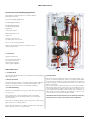
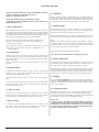
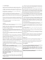
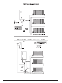
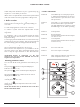
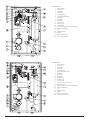
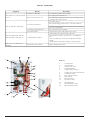
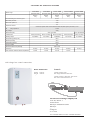
The FUSION Range of Boilers
INSTALLATION
&
TECHNICAL MANUAL
If you require any further assistance:
Telephone: 01698 820533
Fax: 01698 825697
E-mail: [email protected]
Or visit our website
www.electric-heatingcompany.co.uk
Page Contents
INTRODUCTION
PREPARATION
INSTALLATION
ELECTRICAL CONNECTIONS AND CONTROLS
EXTERNAL CONTROL WIRING
INTERNAL BOILER WIRING
EXTERNAL BOILER WIRING
BOILER DIMENSIONS
USER INSTRUCTIONS
FAULT FINDING
TECHNICAL SPECIFICATIONS
2
3
4
7
8
9
10
10
11
13
14
This appliance is not intended for use by persons (including children) with reduced physical, sensory or mental capabilities, or lack of experience and knowledge, unless they have been given supervision or instruction concerning use of
the appliance by a person responsible for their safety.
Children should be supervised to ensure that they do not play with the appliance.
INTRODUCTION
Please read and follow the installation and operating
instructions carefully, to ensure the long life and reliable
operation of this appliance.
The warranty will not cover any damage to the boiler from
poor or incorrect installation work.
The Electric Heating Company may make minor changes
if necessary in the appliance that will not be shown in the
operating instructions, so long as the main features of the
boiler remain the same.
The warranty will not cover water leaks into the boiler. All
plumbing joints must be checked.
The warranty will not cover any call out charges that are a
user or external control fault.
The warranty card should be completed and sent back to The
Electric Heating Company as soon as possible for registration.
A magnetic filter must be fitted to the system in the horizontal
position.
All boilers come with a 24 month warranty that covers all
defects originating from faulty materials and workmanship in
the manufacture of the boilers.
The warranty covers the replacement of any faulty parts and
labour costs.
f.172
2
PREPARATION
Instructions and Building Regulations
This appliance must be fitted in accordance with the
following instructions.
The Local Building Regulations
The Building Regulations
The Building Standards,
(Scotland-consolidated)
Regulations.
Local water bylaws.
British Standards- code
of practice
BS 5449, 1990, forced
circulating hot water systems.
BS 7671, IEE wiring regulations.
BS 4814, 1990, Specification for expansion vessels
(sealed systems only)
C.O.S.H.H.
Materials used in the
manufacture of this appliance
are non-hazardous and no
special precautions are
required when fitting or
servicing this appliance.
PREPARATION
1. Load Check
A load check should be taken into consideration when installing
high output boilers.
LOCATION
2. Boiler location
The boiler can be installed in almost any location within a domestic or commercial property, however consideration should be
given to future maintenance. Never leave the boiler switched off
if there is danger of having temperatures below 0°C in the room
where it is located.
We recommend that a minimum clearance of 450 mm should be
allocated for the removal of the front cover and adequate access
to the boiler plumbing and the internal electrical connections. A
50 mm allowance should be made at either side of the boiler to
allow free flow air into the boiler case and allow access to screws
on the boiler case (150 mm for Slimline model).
The boiler must be fitted on a wall that will provide an adequate
fixing, and should be fitted in a location that the boiler and
pipe-work are not subject to frost and damp conditions.
3. Central heating
Detailed recommendations are given in BS 5449, BS 6700 and
CP 342, Part 2.
Pipes forming part of the useful heating surface should be
insulated to prevent any potential heat loss or frost damage.
(BS 6700:1997).
THE BOILER MUST BE INSTALLED IN THE UPRIGHT POSITION,
FAILURE TO DO SO WILL INVALIDATE THE WARRANTY.
Drain valves should be fitted at the lowest point of the system
pipe work in an accessible position.
Drain valves should be in accordance with BS 2879 and copper
tube to BS 2871. Part 1 is recommended.
f.172
3
INSTALLATION
6. Insulation
The boiler must be installed by a professional plumber or heating
engineer and must be connected to the power
supply by a qualified electrician.
Where practical and if at all possible, we recommend that all
pipe-work be insulated, in particular the primary pipe-work within the boiler cupboard. This is to reduce heat loss and reduce high
cupboard temperatures from exposed pipe-work. (BS 6700).
The Electric Heating Company Ltd will not be held
responsible for faulty installations which are performed by unqualified tradespersons.
7. System Design
1. Pipe Connections
As the boilers are of a low water content an open circuit must be
achieved incorporating 2 metres of continuous 22 mm pipe-work
after boiler connections and before any zone valves.
All Fusion Electric Boilers have a 22 mm compression connection
at the boiler’s flow and return pipes. Please note that the boilers
are supplied with blank washers fitted for transit purposes. These
must be removed and replaced with the washers supplied. The 2
spare pcb fuses supplied must be left inside the boiler.
We recommend the use of an automatic bypass within this circuit
and set to the relevant settings to allow the minimum flow rates to
pass through the boiler (8 l per min) when all radiator thermostats
close.
Allowance should be made for a minimum size radiator of 600mm
x 600mm single convector or equal to 2500 Btu to be installed
within the heating circuit and locked open. This will be located
in the room that has the room stat installed.
The flow (red) and return (blue) are clearly marked on the
external case and under no circumstances should these
connections be reversed.
Hot connections are not recommended at the boiler for future
maintenance and boiler disconnection. Lockshield valves
are recommended
To comply with building regulations, Part L and Part J (in Scotland) room and cylinder stats must be fitted.
2. Case Removal
Note: We do not recommend the use of 8 mm micro-bore pipe.
Remove outer screws from boiler case and push upwards and
outwards taking care to remove internal earth connections. (Slimline model: remove screws on the right hand side and swing the
boiler case open).
Earth connections must be re-connected before the case is reinstated.
8. Water connections
Provisions must be made for the replacement of water lost from
the heating system (sealed systems). Reference should be made to
BS 6798, for the methods of filling and make up of water.
3. Isolation valves
There must be no direct connection between the boilers central
heating system and the main water supply. When mains water is
required to fill the system directly, all Local water bylaws must be
observed. Any connection made must be disconnected after use.
Consideration should be made for the provision of lockshield
isolation valves on the flow and return pipe-work. Such valves
must be full way and not ball valves.
9. Flushing
We recommend isolation valves on each side of the magnetic
filter.
The system must be flushed to ensure that no debris is trapped in
the flow sensor as this may result in boiler failure. Where existing
radiators and pipework are utilised a powerflush must be carried
out to remove debris.
The insertion of ball valves will reduce the recommended flow
through the boiler and promote premature boiler shut down
caused by poor flow rate.
10. System pressures
4. Auto air vents
All boilers are tested to 4.0 bar. The normal working pressure of
the boilers should be set to 1.5 bar. All sealed systems should
comply with the relevant building regulations and standards and
to BS 4814, (Specification for Expansion Vessels).
An Auto air vent is integral within the boiler however an additional auto air vent must be fitted at the cylinder coil if the boiler
is being used for central heating and domestic hot water.
Please Note
In order to protect the Flow Sensor located within the boiler, it
is imperative that you install a mechanical-magnetic filter on the
return inlet to the boiler. This will enable you to clean the filter
at regular intervals and will also ensure that the boiler does not
become contaminated by system residue.
5. Boiler Sizing
Calculate the space heating requirements in accordance with
BS 5449. If the boiler is to heat the domestic hot water, an
allowance of 3kw (10,239 Btu’s ) should be made.
f.172
4
11. System types
2. Add Fernox Heavy Duty Restorer through the header tank or
via a Fernox injector at the recommended dose. One bottle must
be used as a minimum per dwelling. If you are not sure of the
dose rate, then contact Fernox.
The 6,9,12 & 14.4 kW boilers can be used in various system
designs. Please refer to The Electric Heating Company for more
details on our Fusion Boiler for under floor heating. We are able
to supply a heat pack that contains the relevant control valves,
cylinder and room thermostats required to configure an S plan
heating system. The heat pack has all the necessary components
that you need to connect the systems controls and plumbing
configurations for S Plan design.
3. Fill the system back up and circulate the Heavy Duty Restorer
before the boiler is fired up. Then commission the system in
the normal way. The cleansing agent must be in the system
for a minimum of I hour with the system at normal operating
temperature. A longer period of time would be more beneficial to
the cleansing process especially if excess flux was used.
We also recommend the use of thermostatic radiator valves on all
radiators except in the room that has the wall thermostat
fitted. If a bypass radiator has been used in the system, it should
be fitted with lock shield valves and left in the fully open position.
4. Drain and flush the system thoroughly to remove the cleaning
chemical and debris present. This is a crucial part of the cleansing
process and must be done correctly. Use a rinse test meter (TDS),
such as the Fernox CTM. The reading must be within 10% of the
mains ppm value.
If a bypass radiator has not been used then a system bypass of 2
metres of 22 mm copper pipe incorporating an automatic bypass
valve must be used and can be set to 8l/min from the front control
panel.
5. Once the system has been cleansed thoroughly, then add
a Fernox Protector (Copal, MB1 or Superconcentrate), to the
system. The product must be added as per the manufacturer’s
instructions. This will protect against the formation of scale,
corrosion and microbiological growths. lt is crucial, however,
that for a protector to work correctly, the system must be properly
cleansed and flushed.
Systems should be designed to current building regulations.
12. System protection
Failure to protect the system will invalidate the manufacturer’s
warranty.
6. The sticker included within the Fernox Protector carton should
be correctly filled in and attached adjacent to the boiler.
After the system has been installed the cleansing and inhibiting
procedure must be carried out as follows: -
7. Please note: we recommend inhibitor levels are checked on an
annual basis (usually during the service) or sooner if the system
content is lost. This should be carried out using a Fernox inhibitor
test kit.
Fill the system with cold mains water to the recommended
pressure 1.5 bar and check for leaks, then drain the system
thoroughly making sure all drain cocks are fully open and that
the system is completely drained.
8. Fernox Technical Services can be contacted on 0870 8700362
for further assistance.
NB: Motorised valves should be manually opened during the
flushing process and any anti-gravity valves should be by-passed
or removed temporarily.
Add Fernox Heavy Duty restorer through the header tank or via
filling loop at the recommended dose. One bottle must be used
as a minimum per dwelling. If you are unsure of the correct dose
rate, contact Fernox.
If it is necessary to cap off the open vent during the mains flush
to prevent overflow ensure the cap is removed prior to starting
the appliance.
Re-fill the system and circulate the heavy-duty restorer prior
to the boiler entering modulation mode, then commission the
system as normal.
Advice as contained within BS 7593:1992 and PAS33:1999
should be followed in conjunction with this method statement.
The cleansing agent must be in the system for a minimum 1
hour with the system at normal operating temperature. A longer
period of time would be more beneficial to the cleansing process
especially if excess flux was used.
Failure to protect systems will void manufacturers warranty.
Water Loss
Drain and flush the system thoroughly, then add the Fernox
Protector (Copal MB1 or Superconcentrate). This will protect
against the formation of scale, corrosion and microbiological
growths. It is crucial however, that for the protector to work
correctly, the system must be properly cleansed and flushed.
If water loss occurs due to natural evaporation, leakage or any
other breakdown in water seals, the boiler will not operate.
The boilers flow sensor needs a minimum of 4 litres per minute to
operate. If this cannot be achieved the boiler will shut down.
The label included within the Fernox Protector carton should be
completed and attached adjacent to the boiler.
We recommend setting to 8l/min.
Investigation
Note: motorised valves must be manually opened when flushing
the system.
Should BOIL OVER/ BOIL DRY /WATER LOSS occur, investigation
as to why the system has failed MUST take place. Power should
only be reinstated after the fault has been rectified.
Note: If the system is to be drained for any reason, the Fernox
Protector must be re-introduced to the system.
Any further information you may require regarding the protection
and cleansing products, please contact: -
The main overheat stat on the boiler can be re-set, this is
positioned at the top of the boiler market WT3. To re-set, push
the brass pin with a small screwdriver. The pin will click into
place when re-set.
Fernox Technical Helpline on 0870 870 0362.
Fernox Method Statement for New Domestic Systems
ENSURE THAT THE MAINS POWER SUPPLY TO THE BOILER IS
SWITCHED OFF PRIOR TO RE-SETTING.
Cleansing and inhibiting a new central heating installation using
Fernox Heavy Duty Restorer and a Fernox Protector (Copal,
MBI and Superconcentrate).
Procedure:
1. Fill the system with cold mains water to the recommended
pressure and check for leaks, then drain the system thoroughly
making sure all drain cocks are fully open and that the system is
completely drained.
f.172
5
f.172
6
ELECTRICAL CONNECTIONS AND CONTROLS
Programmer/Stat connections
ALL WIRING MUST BE CARRIED OUT IN ACCORDANCE WITH
CURRENT IEE REGULATIONS. BS 7671
The boiler PCB has a voltage free connection for the controls (RP).
Under no circumstances should 240V be connected to the controller block as this will damage the boiler’s PCB and Void the
Manufacturers warranty.
ALL ELECTRICAL CONNECTIONS MUST BE MADE BY A QUALIFIED TRADESPERSON.
A load check should be carried out to ensure that there is a sufficient current and voltage for the intended boiler installation.
Consideration should be taken into account with regard to the
remainder of the properties load requirements.
The stat / programmer connections are clearly marked within the
boiler.
Only after all connections have been made and checked should
the system be filled with water and set to the proper pressure 1.5
bar (Sealed systems)
All boilers must be protected at the meter position with a double
pole fused switch with a minimum of 3mm contact separation. If
the boiler is not fitted local to the meter position then an isolation
switch must be fitted local to the boiler.
THIS APPLIANCE MUST BE EARTHED.
Check the system for leaks. If water leaks into the boiler this may
damage the boiler electrics and the manufacturers warranty will
be invalid.
All pipe work must be earthed in accordance with the current IEE
Regulations – BS 7671
Under no circumstances should the boiler be switched on when
the system is dry.
After completion of all electrical works, an electrical safety check
should be carried out i.e. short circuit, earth continuity, resistance
to earth and polarity check, and all relevant test certificates produced.
The boiler has an inbuilt flow sensor. If the boiler has been
switched on with a low or no water content, the system flow
meter will sense this and prevent the boiler from sending power
to the main elements.
Never open the front cover until all power supplies to the boiler
have been disconnected.
ELECTRICAL CONNECTIONS
After the system has been filled with water and has had a cold
flush the Fernox cleanser should be added, the system filled with
water, purged of air and set to the correct pressure 1.5 bar (sealed
systems). At this point the main power may be switched on.
The boiler connections are clearly marked inside the boiler.
L N (24hr LIVE)
At this stage you may carry out the cleansing and protection of the
system. Refer to the installation section. (See page 5).
The 24hr live is the permanent live connection to the boiler from
the mains supply. External controls will require an independent
fused spur supplied from the consumer unit.
After the cleansing and protection of the system has been done,
set the external controls to the customers selected times.
If an off-peak electric meter has been installed by an Electricity
Company to supply OFF-peak rate electricity at selected times,
the appropriate settings should be entered into to the system programmer to take advantage of the OFF-peak rate electricity.
Boiler Protection
The recommended protection for hard wired boilers are as follows:
Model No.
Boiler size
Protection
FUSION 14.4kW 14.4kW BOILER 80 AMP Protection
FUSION 12kW
12kW BOILER
63 AMP Protection
FUSION 9kW
9kW BOILER
45 AMP Protection
FUSION 6kW
6kW BOILER
32 AMP Protection
CONTROL PANEL WIRING CONNECTIONS
To main
control
board
External controls
We recommend the use of the EHC Select 107XL Programmer
and EHC TLX 4101 room stat for heating only installations.
Flow sensor
To main control board
For Heating and Hot water installations, we recommend the use
of the EHC Select 207XL programmer and heat pack.
Outlet flow
sensor
connection
The heat pack will incorporate all the relevant parts to comply with
current building regulations i.e. Motorized valves to control the
heating and hot water circuits and Room and cylinder thermostats
to control the room and water temperatures. This will also provide
boiler interlock. The use of TRV’s alone will not provide boiler
interlock.
Outlet flow sensor
connection
Inlet return
sensor
connection
Inlet return sensor
connection
Volt free control
connection
Volt free
control
connection
We recommend the use of TRV’s, however they must not be used
in the room that has the room thermostat fitted.
UNDER NO CIRCUMSTANCES
SHOULD A VOLTAGE BE
TAKEN TO THE NA OR RP
CONNECTION AS THIS WILL
DAMAGE THE CONTROL
PCB AND INVALIDATE THE
WARRANTY
Note: this control method is to comply with current building regulations
provided by TACMA, the Association of Controls Manufacturers.
f.172
Flow sensor
7
EXTERNAL CONTROL WIRING
f.172
8
INTERNAL BOILER WIRING
f.172
9
EXTERNAL BOILER WIRING
BOILER DIMENSIONS
Return inlet
f.172
Flow outlet
Return inlet
10
Flow outlet
USER INSTRUCTIONS
3. Front Control Panel
Unlike other system boilers such as Gas, Oil and Propane, the
FUSION range of electric boilers require no ignition or lighting
sequence to be executed by the end user.
Indicator B
When GREEN light is on the pump is operat
ing. When this light flashes the flow rate is in
sufficient (less than 5 l per min) Refer to tech
nical specifications
Indicator C
ture
When light is off room thermostat temperahas been achieved. (RP is open) When the
green light flashes the NA connection is open.
When RED light is on, the boiler is operating
When GREEN light is on boiler temperature
has been achieved.
Indicator F
Set Temperature
Indicator D
Return Temperature
When this indicator flashes the return temper
ature sensor is faulty.
Indicator E
Flow Temperature
When this indicator flashes the flow tempera
ture sensor is faulty.
2. Temperature Setting
Indicator G
Press to show Flow, Return and Set Temperature
We recommend boiler temperature to be set to 65°C.
Raise and lower the temperature in your installation with the
use of the switches and . Refer to the diagram opposite to learn
how to adjust the right temperature to make the boiler work
comfortably and economically.
Indicator H
Press to check flow rate
Indicator I
Press to check power consumption
Indicator A
DHWC Indicator
ATTENTION: Should the temperature on the front
panel be set on too low value the boiler will not reach the
required room temperature.
Indicator K
DHWC temperature indicator (when electronic
DHWC temperature sensor is used)
All the end user is required to do is ensure that the system is filled
with water and the room stat or programmer is calling for heat.
I. Boiler operation
1.1 Switch on unit power supply. Press to switch the boiler on.
Switch the boiler off using the same switch by holding it for
2 seconds.
1.2 Switch on programmer or room stat to call for heat.
1.3 When the system reaches the required boiler set point
temperature the boiler will modulate and will automatically
stage down.
1.4 Modulation - this is when the boiler controls the heating
load and the power that is required to maintain the relevant
temperature setting.
1.5 During the periods when the boiler is switched off the pump
will operate every day for 15 minutes. This protects the boiler and
the central heating system from being blocked and silted up.
Working parameters control
You can check all the working parametres of the boiler by pressing .
First pressing of
switch inlet temperature displayed
(indicators “D” and “E” on),
Next pressing of
switch – outlet temperature displayed
(indicators “F” and “E” on),
Next pressing of
switch – medium (water) rate of flow
displayed (indicator “H” on),
Next pressing of
switch – power with which the boiler
currently heats (indicator “I” on)
Next pressing of
switch – returns to the “standard” state,
where you can change the temperature setting in the central
heating system.
NOTE: The indicators not only describe the state of the boiler
but also inform about failures.
f.172
11
Slimline boiler
1
2
3
4
5
6
7
8
9
10
11
12
PF
PN
L
PE
N
M
RP
-
heat exchanger
flow sensor
manometer
safety valve
circulating pump
safety temperature limiter
return inlet
flow outlet
ZIO board
power board
automatic vent
control board
points of electric mains connection (phases)
electrical connections
live
permanent earth
neutral
boiler fixing positions
control stat connections
Fusion boiler
1
2
3
4
5
6
7
8
9
10
11
12
13
14
PF
PN
L
PE
N
M
RP
f.172
12
-
heat exchanger
flow sensor
manometer
safety valve
circulating pump
safety temperature limiter
return inlet
flow outlet
ZIO board
power board
automatic vent
control board
expansion vessel connection
expansion vessel
points of electric mains connection (phases)
electrical connections
live
permanent earth
neutral
boiler fixing positions
control stat connections
FAULT FINDING
Symptom
Reason
Procedure
No power to the boiler
The indicators on the front panel
are off
Check electricity mains power supply
Check the power board fuse F2
Main over heat stat cut-out
Check the WT3 temperature safety cut-out investige cause
- possibly fault / return sensors
Check flow sensor
The central heating system airlock - vent the central heating system and the pump
Flow sensor is blocked
The „B” indicator is flickering
Check for choked pipes
Circulating pump is blocked
Move the pump rotor manually
Flow sensor failure
check the flow sensor and replace if neccesary.
Find the failure reason then replace the fuse.
The room thermostat indicates
that the boiler is switched on.
„C” indicator does not light
Control panel fuse failure
The „D” or „E” indicator are
blinking
Temperature sensor failure
2
Check external controls, room stats, etc. are calling for
heat.
Link out control stats connections to eliminate external
controls
If boiler operates the fault is with the external controls
Replace temperature sensor.
3
1
boiler key
1.
2.
3.
4.
5.
6.
7.
8.
9.
10.
11.
12.
13.
14.
15.
16.
4
7
9
5
6
10
8
12
11
15
16
14
f.172
13
13
Control Panel
Over Heat Stat
Automatic Air Vent
Heating Elements
Copper Heat Exchanger
Printed Circuit Board
Voltage Free Control Connections
Circulation Pump
Flow & Return Sensors
Flow Switch
Pressure Guage
Expansion Vessel
Heating Flow
Heating Return
Pressure Relieve Valve
White Metal Enclosure
TECHNICAL SPECIFICATIONS
Boiler range
Fusion 6kW
(EHCFUS 6kW)
Fusion 9kW
(EHCFUS 9kW)
Fusion 12kW
(EHCFUS 12kW)
Bottom
Entry
Bottom
Entry
Bottom
Entry
Pipe entry from boilers
Central heating flow & return pipes
Bottom
Entry
Bottom
Entry
22 mm
Min water pressure
1 bar
Max water pressure
3 bar
6 lt.
Expansion vessel
maximum system water volume about 60 litres at initial system pressure 1,5 bar
V
Vessel
charge pressure
1,5 bar
Dry weight
25kg
Electrical supply
Load/current
Fusion 14.4kW
Fusion 24kW
(EHCFUS 14,4kW) (EHCFUS 24kW)
240V 1ph 50Hz
415V 3ph N 50Hz
240V; 25,0 Amp
240V; 37,5 Amp
240V; 50,0 Amp
240V; 60,0 Amp
415V; 33,4 Amp
20,478 Btu
30,717 Btu
40,956 Btu
49,147 Btu
81,912 Btu
40 Amp
Heating output
Temp setting (factory set)
85°C
Min temp setting
40°C
Overheat Protection
100°C
Pump included
Yes
Recommended Pump settings
Set to max
Protection
32 Amp
45 Amp
63 Amp
80 Amp
The maximum allowed network impedance
0,39 Ω
0,32 Ω
0,24 Ω
0,22 Ω
NB: Voltage free control connections
Boiler Dimensions
Controls
Width
Height
Depth
Central Heating Only:
EHC Single Channel Heat Pack
420mm
700mm
285mm
Central Heating & Domestic Hot Water:
EHC Twin Channel Heat Pack
The Electric Heating Company Ltd
Unit 40, Block 5
Third Road
Blantyre Industrial Estate
Blantyre
Glasgow
G72 0UP
Tel: 01698 820533 Fax: 01698 825697
f.172
14