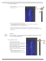
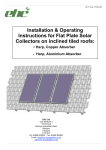
1
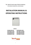
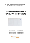
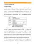
Rev 5; Issue : 19 May 2011
Installation & Operating
Instructions for Flat Plate Solar
Collectors on inclined tiled roofs:
- Harp, Copper Absorber
- Harp, Aluminium Absorber
EHC Ltd
Unit 40 Block 5
Third Road
Blantyre Industrial Estate
Blantyre
Glasgow
G72 0UP
Tel: 01698 820533 Fax: 01698 825697
Email: [email protected]
www.ehc-renewables.co.uk
Installation and operating instruction for flat plate solar collectors ES2DU0 & ES3TRI range — inclined tile roof.
Contents:
1.
1.1.
1.2.
1.3.
1.4.
1.5.
1.6.
2.
2.1
2.2
2.3
2.4
2.5
2.6
General information
4
ES Solar Collector
Types of Solar Collectors
Technical data table
Efficiency graph
Domestic hot water heating installation diagram
Identification labels
4
4
4
4
5
5
Safety instructions
6
General
Working at height
Lightning protection
Installers
Mounting kits
Risk of burn injury
6
6
6
6
6
6
2.7 Transportation, storage and handling
3.
3.1
3.2
3.3
3.4
3.5
4.
Pre-Installation
7
Collector mounting kit
Technical documentation
Tools and additional equipment
Collector location
Key dimensions.
7
8
8
8
8
Collector Installation
9
4.1 Roof fixing
4.2 Mounting Rails connection
4.3 Mounting Rails assembly
4.4 Locking screws for Collector Clamp
4.5 Assembly of Collector Graspers
4.6. Assembly of Collector
4.7 Assembly of additional Collectors
4.8 Hydraulic connection
4.9 Inspection after assembly
4.10 Inlet connection
4.11 Outlet connection
4.12 Temperature sensor
4.13 Collecting pipes
5.
Final Installation & Inspection
5.1 Check-up
5.2 Venting
5.3 Insulation
6.
7.
6
Maintenance and service
Guarantee
9
10
10
11
12
13
14
14
15
15
16
16
17
18
18
18
18
18
20
3
Installation and operating instruction for flat plate solar collectors ES2DU0 & ES3TRI range — inclined tile roof.
1.
General information
1.1. ES Solar Collector
ES range of solar Collectors are intended to heat water for domestic properties and public utility
buildings. The ES Collectors can also be used to support central heating systems and heat water for
swimming pools.
1.2. Types of Solar Collectors
ES4210709 ES4210808 ES4210709 ES4210808 -
Harp Solar Collector, copper absorber, surface area 2 m2
Harp Solar Collector, aluminium absorber, surface area 2 m2
Harp d o u b l e Solar Collector, copper absorber, surface area 2 m2
Harp double Solar Collector, aluminium absorber, surface area 2 m2
ES4211805 -
Harp Solar Collector, aluminium absorber, surface area 2,3 m2
1.3. Technical data table
Flat Plate Solar Collector
ES4210709
Width
mm
Height
mm
Depth
mm
Weight
kg
Absorber
ES4210808
ES
ES4211805
1072
2119
2424
90
36,5
copper
41,8
aluminium
copper
aluminium
Collector surface area
m2
2,27
Absorber surface area
m2
2,0
2,6
2,3
Active surface area of
absorber
Optical efficiency 1
m2
1,98
2,28
%
81,5
80,1
77,0
Heat loss coefficient 1
W/m2K
3,49
3,89
4,62
Heat loss coefficient 1
W/m2K2
0,004
0,005
0,003
Connections: Cu pipe
mm
Liquid content
litre
Max. working pressure
bar
6,0
l/min
1-4
Flow: min — max.
18
1,13
1,4
1
Following parameters: active surface area of absorber (for G=800 W/m2) - on base of research carried out at Institute for Fuel and Renewable Energy in
Warsaw
1.4. Efficiency graph
Solar Collectors
efficiency graph is
related to the active
surface area of absorber
(for G=800 W/m2)
4
Installation and operating instruction for flat plate solar collectors ES2DU0 & ES3TRI range — inclined tile roof.
1.5. Domestic hot water heating installation diagram
I - Solar pump group
2 - Valves for filling, emptying and flushing of Solar circuit
3 - Hot water tank
Ti - Collector temperature sensor
Ti - Tank temperature sensor
K - Solar Collector
NW - Expansion vessel
ZB - Safety valve
ZW - Cold water inlet
CW - Hot water outlet
Solar installation must be in compliance with the BS EN 12975/12976 norm.
1.6. Identification labels
An identification label is placed on the both
sides of the Collector (at the bottom).
Additionally, the warning a n d information
icons are placed on the left side of
Collector.
User - Be aware.
i
The user is obligated to replace the identification labels where these are unable to be read.
5
Installation and operating instruction for flat plate solar collectors ES2DU0 & ES3TRI range — inclined tile roof.
2.
Safety Instructions
2.1
General
Please carefully read and understand these instructions before installing the EHC Thermal Solar
System in order to ensure: a safe, risk free installation and trouble free operation. Following
installation and commissioning of the system the operation of the system and associated controls should
be explained to the customer and these instructions left with them for future reference.
EHC Thermal Solar System must be installed in accordance with the manufacturer’s instructions and all
relevant regulations in force at the time of installation. The EHC Thermal Solar System is subject to
Building Regulation G3 (England and Wales), Technical Standard P3 (Scotland) or Building Regulation P5
(Northern Ireland). Installation and must be carried out by a competent person.
2.2
Working at Height
It is mandatory that the Working at Height Regulations (WAHR) is adhered to at all times. A site Risk
Assessment must be conducted before operations take place such that suitable precautions are put in
place to eliminate or at the very least minimize risks of injury; not only to installers but to also protect the
general public.
2.3
Lightning Protection
If the Solar Collector System is installed over a height of 20 M and the building is without a lightning
protection system then couple the electrically conductive elements to the earth (min earth section – 16mm)
and the equipotent bonding elements of the installation.
If the Solar Collection System does not exceed a height of 20 meters then a lightning protection system is
not necessary. Where a building is equipped with a lightning protection system then we strongly
recommend that suitably qualified and competent lightning equipment installer is used to connect the EHC
Solar Installation to the existing lightning protection system.
2.4
Installers
It is strongly recommended that MCS Certified Installers are used in the installation or servicing of EHC
Thermal Solar Systems
2.5
Mounting Kits
It is mandatory that only EHC Solar Collector Mounting Kits are used to support the EHC Solar
Collectors and failure to carry this out may increase the risk of personal injury and/or damage to the
property
2.6
Risk of burn injury
The solar Collectors and assembly elements may be hot due to radiation and therefore
there is a risk of a burn injury. As a result the guidelines below should be followed in order to avoid
burn injuries:
- use personal clothing (e.g. Overalls, gloves, etc)
- put a canvas cover on the Collector housing
- wait for temperature to go down before starting work on the unit
2.7. Transportation, storage and handling
• Transport the Collectors in original manufacturer’s package & according to package marking.
• Carefully handle and do not overturn or stack u n p a c k e d Collectors
• Packed Collectors must be handled by forklifts or pallet jack
• Protect against inclement weather conditions if stored in the open air.
• Keep dry at all times
• The unpacked Collector must be carried by at least two people.
• Collector can be carried manually or by carry straps in either the horizontal or vertical position.
• Do not use tools that can scratch a Collector surface (e.g. steel cords, chains, metal hooks etc.).
• Always use lifting equipment (such a ladder hoists, pulley, swing hoists, or truck-mounted
cranes/conveyors) to transport the Collector onto the roof.
• Never touch connectors while holding/carrying/lifting solar Collectors.
6
Installation and operating instruction for flat plate solar collectors ES2DU0 & ES3TRI range — inclined tile roof.
3.
Pre-Installation
3.1 Collector Mounting Kit
Mounting Kit items:
Number of Collectors
1
2
Item Name
3
4
5
4
2+2
4
Quantity
1
Profile Rail
2
2
2
Roof fixing
4
6
8
10
12
3
Clamp
4
8
12
16
20
4
Collector Grasper
2
4
6
8
10
5
Profile connector
0
0
2
2
2
6
Locking screw (screw M8x20, nut M8, washer,
ser- rated lock washer,)
8 set..
14 set..
20 set..
26 set..
32 set..
7
Self-tapping screw
0
0
4
4
4
8
Wood screw No. 6 x 40
4
6
8
10
12
Ensure the Mounting Kit is assembled correctly as above, any damaged items must be replaced by the
original items only.
7
Installation and operating instruction for flat plate solar collectors ES2DU0 & ES3TRI range — inclined tile roof.
3.2. Technical documentation
The EHC Thermal Solar Kit contains various types of components and it is therefore
important that the relevant installation instructions of these items are carefully read before
installation/mounting:
•
•
•
•
Solar Collector
Pump group
Solar controller
Solar hot water cylinder
3.3. Tools & additional equipment
•
•
•
Sprit level
Safety harness for use with a safety rope
Scaffolding, ladder or lift
3.4. Collector location
The Solar Collector surface must be in perpendicular position to the sun’s rays to obtain the
most efficient radiation absorption and there fore must be installed on the south side of inclined
roofs
Recommended Collector position.
-
Angle to sun
40º — 450 (all year round)
30º approx. (summer time)
60º approx. (winter time)
•
•
•
•
Maximum snow and wind load capacity — 2,0 kN/m².
Do not install solar Collectors if the slope value is less then 15° and more then 75º
There should be no shading from trees, chimneys and neighbouring tall buildings.
For Collectors in a row the row-to-row solar panel shading has to be considered.
Note: The information and drafts in this instruction refer to the vertical Collector assembly only.
3.5. Key dimensions.
Quantity of Collectors (per set)
1
2
1100
2200
Dimension
A
B
8
3
4
5
Dimensions values [ mm ]
225
3300
4450
220
5600
Installation and operating instruction for flat plate solar collectors ES2DU0 & ES3TRI range — inclined tile roof.
4.
Collector Installation.
4.1. Roof fixing
Having decided on the location for the Collector, locate the in ternal hori zontal roof rafters.
Bear in mind that lower roof rafter must be located approx. 600 mm above bottom edge of the
Collector mounting position, whereas the upper roof rafter must be located approx. 1600 mm ±
200 above it. Remove some roofing tiles to get access to the roof rafters.
Horizontal roof
rafter
Fix to the roof by using No 6 x 40 wood screws and maintain the “A” value distance between
roof fixing points.
Important
i
The roof fixing values distances a re only
approximate values.
9
Installation and operating instruction for flat plate solar collectors ES2DU0 & ES3TRI range — inclined tile roof.
4.2. Mounting Rails connection
For three or more Collector sets the
mounting Profiles must be connected.
Put the half-length of Profile Rail
connector (5) into the one of the ends of the
Profile Rail (1), and then secure it by fixing
the self-tapping screw (7) — approx. 50 mm
from Profile Rail edge (1).
Put the next Profile Rail (1) into the
second end of the connector (5), and then
secure it by fixing the self-tapping screw
(7). Make sure that the Profile Rail edges
(1) are placed parallel to each other.
Repeat for all Profile Rail sets.
I
Important.
If installing 4 Collectors, make sure that two fixed sets of Rails have the same length
4.3. Mounting Rails assembly
Fix Profile Rail (1) into the double
threaded bolts (2) using a locking screw
(6).
Fix the locking screws (6) into the Profile
Rail (1) with as many screws as doubled
threaded bolts (2), Spacing between the
locking screws (7) must be the same as
Fix the locking screws (6) into the double
for the doubled threaded bolts (2).
t h r e a d e d bolts (2), and then lock the nut lightly.
locking screw (6)
I
10
Important.
Elements of locking screw kit: 1) screw M8 x 20,2) washer,3) serrated lock washer,4)
M8 nut
(Strictly follow above sequence when locking).
Installation and operating instruction for flat plate solar collectors ES2DU0 & ES3TRI range — inclined tile roof.
Repeat for next row of roof fixing (2), then level the Profile Rail edges (top and bottom) and
tighten up all locking screws (6).
i
Important.
Depending on the type of tiles, some
tile material may need to be
r e m o v e d i n o rd e r to put the tiles
back into position
4.4. Locking screws for Collector Clamp
Put the locking screws (6) into the Profile Rail
(top and bottom) to fix the Collector Clamp
(3). Put the locking screws into the Profile
Rail (1) as shown on the picture.
There are two Clamps (3) between Collectors
so two locking screws (6) must be fixed and only
one Clamp (3) on the edge set.
At this stage, you can put aside the locking
screws (6) for Collector e dges to fix them after
you place the Collectors. The screws for Clamp
(3) between Collectors have to be located
symmetrically toward the Profile Rail centre.
(Space requirements: approx. 1130 mm).
11
Installation and operating instruction for flat plate solar collectors ES2DU0 & ES3TRI range — inclined tile roof.
4.5. Assembly of Collector Graspers
Fix Collector Graspers (4) onto bottom
Profile Rail (1). Hook the Collector
G r a s p e r onto bottom Profile Rail (1) and
push downward to the final position.
Locate the first Grasper (4) at “B” distance
away from Profile edge. For the other
graspers keep the distance of 700mm and
440mm (alternate).
i
12
Important.
The distance between Collector Graspers is maintained correctly when the last
Grasper is at “B” distance away from opposite edge of Profile Rail.
Installation and operating instruction for flat plate solar collectors ES2DU0 & ES3TRI range — inclined tile roof.
4.6. Assembly of Collector
Check all connections before first Collector installation.
Important.
i
Protect Collector against p o t e n t i a l damage (slide and fall accidents) t h a t could
occur when transporting solar Collectors on the roof.
Position the bottom edge of Collector
against the Profile Rail (1). Slide the
Collector carefully onto the two Graspers
(4) then lean the Collector on the top
Pr o f i l e Rail (1).
Place
the
Collector
symmetrically towards Graspers
(4) then fix the four Clamps (3).
Fixing the Clamps:
Put the
Clamp (3) onto locking screw
(the screw (6) that was placed
into the Profile Rails (1) earlier see sub-clause 4.4), then bring
two elements as close as
possible to Collector and put the
Clamp (3) onto Collector angle
bar. Next, put a washer, serrated
lock washer i n t o p o s i t i o n
and lock the nut lightly.
Adjust the final position of Collector.
13
Installation and operating instruction for flat plate solar collectors ES2DU0 & ES3TRI range — inclined tile roof.
4.7. Assembly of additional Collectors
Additional Collectors included in the set
(excluding one piece Collector set) must
be fixed on the Profile Rail (1), follow the
installation work sequence described in
sub-clause
4.6 and make a hydraulic
connection of Collectors at the same time
(according to sub-clause 4.8).
Keep the distance between the Collectors
relatively constant (approx. 64 mm).
4.8. Hydraulic connection
1 - Collector connector
2 - Nut
3 - Clamping ring
4 - Expansion joint
i
Important
Maximum number of Collectors in one row is 5 pieces.
-
i
14
The correct Collector connection sequence is:
undo the nut (2) then put the nut onto connector (1),
put the Clamping ring (3) onto connector,
lock the nut (2) into expansion joint (4),
put the nut onto connector of second Collector,
put Clamping ring onto connector of second Collector,
bring second Collector near to expansion joint,
lock the nut onto expansion joint.
Important.
Tighten the lock nut tight enough to ensure a seal that is sufficient to guard against
leaks. Do not tighten the nut with too much force to avoid damages of connector
and expansion joint.
Installation and operating instruction for flat plate solar collectors ES2DU0 & ES3TRI range — inclined tile roof.
4.9. Inspection after assembly
After the hydraulic connection has been completed, double check that all connections are
tight and secure. Make sure all Collectors are firmly fixed to the mounting structures.
4.10. Inlet connection
i
Important.
Hydraulic connection elements can be fitted to either the right or the left side of
Collectors.
1 -Fflexible insulated hose 3/4’’
2 - Clamping elbow
3 - Collector connector
The correct inlet connection sequence is:
- put the elbow nut (2) onto Collector connector (3),
- put the Clamping ring onto Collector connector,
- lock the nut onto elbow,
- lock the flexible hose nut (1) onto elbow
- connect flexible hose to solar installation system
15
Installation and operating instruction for flat plate solar collectors ES2DU0 & ES3TRI range — inclined tile roof.
4.11. Outlet connection
1 - Collector connector
2 - cross pipe with manual air vent and immersion sleeve
3 - flexible insulated hose 3/4”
The correct outlet connection sequence is:
- use the Clamping piece to connect cross pipe (2) to Collector connector (1),
- lock flexible hose (3) onto cross pipe (2),
- connect flexible hose to solar installation system.
Standard Solar Mounting Kit includes manual air vent, however you can install an
automatic vent instead. For the automatic air vent install ball valve (between cross pipe
and air vent).
i
Important.
As solar systems reach high temperatures, installation of the vents and valves
m u s t b e made of metal only.
4.12. Temperature sensor
Solar system malfunctions
Most solar system malfunctions are caused
by faulty temperature sensor installation or
damage to the signal cable.
To prevent damage to the signal cable by
birds or rodents ensure the signal cable is
encased by a corrugated pipe.
Install temperature sensor into immersion
sleeve.
- insert temperature sensor all the way
down into immersion heater,
- prevent Clamping spring from sliding out
16
Installation and operating instruction for flat plate solar collectors ES2DU0 & ES3TRI range — inclined tile roof.
4.13. Collecting pipes
Use flexible insulated hoses to make hydraulic connection to collecting pipes.
Connection of flexible hoses with solar installation must be made below vent valve
level.
Do not connect inflexible collecting tubes directly to Collector.
Important.
Run the solar tubes through the roof by universal pass through for roofing or air shaft.
i
Important.
Run the temperature sensor wire along with return flexible hose.
Consideration must be given to the diameter of solar tubes. The proper diameter of tubes is
determined by flow rate of heating medium: 0, 4 ÷ 0, 7[m/s1.
The table below shows the diameter of tubes (recommended) according to quantity and type
of solar Collectors.
ES Collector
Number of
Collectors
Collector Arrays
Diameter of collecting
tube
[mm]
1
12 x 1
2
15 x 1
3
1
4
18 x 1
5
6
8
2
22 x 1
10
17
Installation and operating instruction for flat plate solar collectors ES-2,0; ES-A-2,0 & ES-A-2,3 — inclined tile roof.
5.
Final Commissioning
5.1 C h e c k -Up
Once the installation has been completed the system must be flushed, hydraulic tested and system
filled with Solar Fluid. In order to carry out these tasks a solar pump and expansion vessel need to be
installed. Please refer to the manufactures installation & operating instructions for operation of these
items.
The following steps require to be completed:
- make sure all elements of solar installation are fixed correctly,
- flush the pipe system,
- perform hydraulic pressure testing,
- fill the system with solar fluid.
5.2 Venting
Use charging-de-aerating station for filling and flushing solar installations. When the automatic air
vent opens you must turn off the ‘ shut-off valve’ once the venting has been completed. This ‘shutoff’ valve is located before t h e vent.
5.3 System protection
Once the above system testing has been carried out the Thermal Solar Collectors must be protected
from the heat of the sun & potential damage from birds and rodents. A waterproof & heat resistant
insulated cover must be fitted over the complete Thermal Solar installation (i.e. including all electrical
sensors & control cables) .
6.
Maintenance and Service
-
Maintenance personnel should, before starting work, conduct r i s k a s s e s s m e n t s a n d take
s u i t a b l e p r e c a u t i o n s i n o r d e r t o p r e v e n t slips, trips and fall accidents.
When moving the Collector to carry out maintenance work, e n s u r e these are secured prevent
falling.
Use suitable tools and equipment.
Use p e r s o n a l p r o t e c t i v e e q u i p m e n t ( e . g . protective gloves, o v e r a l l s boots,
etc.)
Check Collector temperature before executing an y maintenance work; do not a t t e m p t
maintenance while Collector is hot.
Solar system inspection must be carried out according to warranty guide of any supplied
components.
Annual routine maintenance checks are recommended to assure trouble free solar system
operation.
Frost Protection: Determine the frost resistance of solar fluid using the refractometer. Refill and
vent the solar circuit, if the frost resistance of liquid drops below —200C
System Pressure: Control the working pressure of solar circuit (drop pressure should not
occur).
Expansion Vessel: control the initial pressure of expansion vessel. Disconnect the expansion
vessel from the system and determine the rate of pressure. The initial pressure should be 0, 3 bar
lower than filling pressure (i.e. Normally 2, 5 to 3 bar).
Cleaning the Collectors: When necessary clean the Collector using a general cleaning solution
(i.e. mix the washing soda or soap liquid with water) then a p p l y a n d rinse with water.
Control and safety system: Check the control and safety system as well as support structure of
Collectors.
It is recommended that maintenance is carried out by a MCS Certified Installer to assure
continued reliable performance of the system
18
Installation and operating instruction for flat plate solar collectors ES2DU0 & ES3TRI range — inclined tile roof.
7
Guarantee
The EHC Thermal Solar System is guaranteed against faulty materials or manufacture provided that:
•
It has been correctly installed as per this
document and all the relevant standards,
regulations and codes of practice in force at the
time.
•
It has not been modified in any way, other than by
the manufacturer.
•
It has not been misused, tampered with or
subjected to neglect.
•
It has only been used for its intended purpose
•
It has not been subjected to frost damage
•
The unit has been serviced annually
•
The guarantee period starts from the date of
purchase and no registration is required.
•
The extended guarantee is not transferable, and rests
with the original householder.
•
The system is fed from a public water supply.
The following Guarantee periods apply from date of purchase
Solar Collectors & Mountings
Electrical componnts & equipment
10 years
2 years
Please note that invoices for servicing may be requested to prove that the unit has been
serviced annually by a competant MCS certified installer/service person.
EXCLUSIONS – THE GUARANTEE DOES NOT COVER the effects of scale build up, any labour charges
associated with replacing the unit or its parts, nor any consequential losses caused by the failure or
malfunction of the unit.
For advice, support, or further information on EHC’s full range of heating products, call now on 01698
820 533.
The EHC Ltd, Unit 40, Block 5, Third Road, Blantyre Industrial Estate, Blantyre,
Glasgow, G72 0UP
Tel. 01698 820533
Fax. 01698 825697
[email protected]
www.electric-heatingcompany.co.uk
19