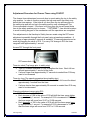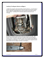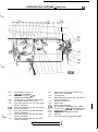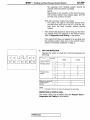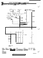
1
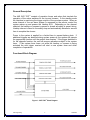
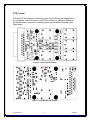
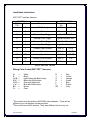
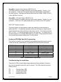
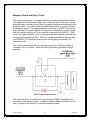
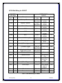
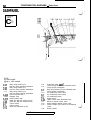
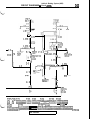
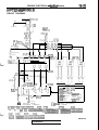
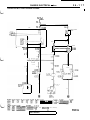
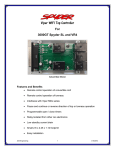
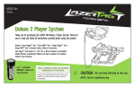
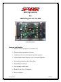
WIFI Top Controller For 3000GT Spyder SL and VR4 Actual Size Shown Features and Benefits Remote control operation of convertible roof Remote control operation of tonneau Interfaces with most multi channel car alarm systems Interrupt and reverse direction of top or tonneau operation Automatic continuation after Safety Stop Adjustable closure timer Low standby current drain Small 2.6 x 4.25 x 1.12 footprint Easy installation JNS Engineering 1 3/28/2009 Table of Contents General Description .......................................................................................3 Functional Block Diagram ..............................................................................3 Pin Assignment..............................................................................................4 Functional Description ...................................................................................4 Specifications.................................................................................................5 PCB Layout...................................................................................................6 Installation Instructions ..................................................................................7 Wiring Color Codes (WIFI TOP™ Harness)....................................................7 Wiring the Harness ........................................................................................8 Audiovox APS-996a Specific Programming...................................................9 Troubleshooting the Installation .....................................................................9 Remote Top Testing ....................................................................................10 Adjustment Procedure for Closure Timer using R19/R37 ............................11 Remote Start Neutral Safety Switch ............................................................12 Installing The Magnetic Switch and Magnet ................................................13 Magnetic Switch and Relay Circuit ..............................................................14 Installing the APS-996a Alarm .....................................................................15 APS-996a Wiring for 3000GT ......................................................................16 Wiring Color Codes (APS-996a Alarm)........................................................17 APS-996A Tach Programming.....................................................................17 Remote Start Safety Tests...........................................................................18 How to Read the 3000GT Wiring Diagrams.................................................18 3000GT Specific Wiring diagrams ...............................................................18 Table of Tables Table 1 - Pin Assignment...............................................................................4 Table 2 - Specifications .................................................................................5 Table 3 – WIFI TOP™ Harness ......................................................................7 Table 4 - APS-996a Specific Programming ...................................................9 Table 5 - APS-996a Wiring for 3000GT .......................................................16 Table of Figures Figure 1 - WIFI TOP™ Block Diagram............................................................3 Figure 2 – PCB Top Side Artwork..................................................................6 Figure 3 – PCB Bottom Side Artwork.............................................................6 Figure 4 - Neutral Safety Circuit...................................................................14 JNS Engineering 2 3/28/2009 General Description The JNS WIFI TOP™ consists of precision timers and relays that simulate the operation of the rocker switches for the top and tonneau. In the standby mode the Interface is monitoring the trigger outputs of the car alarm system. When an extra channel of the car alarm system is accessed by the remote control the system wakes up and powers the Hardtop ECU. Depending on the channel selected, the hardtop or tonneau is opened or closed according to preset timing. Hardtop closure is timed to the safety stop and automatically actuated a second time to complete the closure. Power to the system is applied for a limited time to prevent battery drain. If additional triggers are detected during system power up, the system will operate the appropriate function until the system timer expires. If the trigger detected is for the opposite function, the unit will reverse operations subject to the system timer. If the system timer times out while the hardtop or tonneau is being actuated the next trigger received will start a new system timer and allow completion of operations. Functional Block Diagram Figure 1 - WIFI TOP™ Block Diagram JNS Engineering 3 3/28/2009 Pin Assignment DB25 PIN 1 2 5 6 7 8 10 11 12 13 14 DESCRIPTION +12V (Battery) Gnd Tonneau Open Trigger Hardtop Close Trigger Tonneau Close Trigger Hardtop Open Trigger Tonneau Open Actuator Tonneau Close Actuator Hardtop Open Actuator Hardtop Close Actuator +12V (Ign2) Table 1 - Pin Assignment Functional Description ***CAUTION*** Care should be taken to stand clear of the top mechanism during remote activation. Once activated, the mechanism will operate automatically until the timers expire. Tonneau Open An active low pulse on the tonneau open trigger starts a 68 second system timer and an 8 second timing cycle to open the tonneau. The tonneau open trigger also terminates an active tonneau close cycle allowing the operator to reverse operations without waiting for an active cycle to complete. Tonneau Close An active low pulse on the tonneau close trigger starts a 68 second system timer and an 8 second timing cycle to close the tonneau. The tonneau close trigger also terminates an active tonneau open cycle allowing the operator to reverse operations without waiting for an active cycle to complete. Hardtop Open An active low pulse on the hardtop open trigger starts a 68 second system timer and a 29 second timing cycle to open the hardtop. The hardtop open trigger also terminates an active hardtop close cycle allowing the operator to reverse operations without waiting for an active cycle to complete. JNS Engineering 4 3/28/2009 Hardtop Close An active low pulse on the hardtop close trigger starts a 68 second system timer and a 251 second timing cycle to close the hardtop to the safety stop. A second timer automatically fires for 13 seconds to complete the top closure. The hardtop close trigger also terminates an active hardtop open cycle allowing the operator to reverse operations without waiting for an active cycle to complete. If a hardtop open cycle is terminated quickly after it was started, the hardtop close command will cause the hardtop to delay at the safety stop for a period of time. ***EXTREME*** care should be taken to avoid touching any part of the mechanism until the operations are completed Specifications Parameter Input voltage Input current Trigger voltage Sink current Output voltage Source current Source current Tonneau open time Tonneau close time Hardtop open time Hardtop close to Safety time Hardtop close Time System active time Pin 1 1 5,6,7,8 5,6,7,8 10,11, 12,13, 14 14 10,11, 12,13 Test conditions Min Active trigger Active 12 Units V mA V mA V Active Active 20 20 A A 8 S 8 S 29 S Standby R19 =174K1 Typical 12 5 Max 4 5 22 25 27 S 13 S 68 S Table 2 - Specifications 1 Hardtop to safety time can be changed by turning the screw for R37 which can be reached through the front panel. JNS Engineering 5 3/28/2009 PCB Layout R19 and R37 are located on the bottom side of the PCB and are highlighted in the red boxes. Some versions of the PCB do not have a silkscreen legend on the bottom side so you need to carefully match up the artwork features to the figure below. Figure 2 – PCB Top Side Artwork Figure 3 – PCB Bottom Side Artwork JNS Engineering 6 3/28/2009 Installation Instructions WIFI TOP™ Interface Harness SOURCE DB 25 Color PIN 1 R Description +12V (Battery) DESTINATION Connector Color - Pin C59-6 W 2 B Gnd Chassis B 5 W Tonneau Open Trigger Dark Blue Wire1 6 Y Hardtop Close Trigger Light Blue/Green Wire1 7 O Tonneau Close Trigger Light Blue/Black Wire1 8 G Hardtop Open Trigger Light Blue/Red Wire1 10 L Tonneau Open Actuator D48-10 LG-B2 11 P Tonneau Close Actuator D48-9 B-W2 12 BR Hardtop Open Actuator D48-3 GR-R2 13 GR Hardtop Close Actuator D48-11 L-W2 14 CL +12V (Ign2) D48-4 R Table 3 – WIFI TOP™ Harness Wiring Color Codes (WIFI TOP™ Harness) W B LG-B B-W GR-R L-W BR CL = = = = = = = = White Black Light Green with Black stripe Black with White stripe Grey with Red stripe Blue with White stripe Brown Clear R Y O G L P GR = = = = = = = Red Yellow Orange Green Blue Purple Grey 1 Wire colors from the Audiovox APS-996a extra channels. These will be different if you use another car alarm system. 2 Wire colors from the 3S manual. They were different colors in my car. JNS Engineering 7 3/28/2009 Wiring the Harness Red Wire: +12V Input (DB25 Pin 1) Connect this wire to the +12VDC constant source found at the ignition harness connector C59 pin 6 located under the driver side dash. It is the White wire. Use a fused connection or tie in after the car alarm system fuse. Black Wire: Gnd (DB25 Pin 2) Connect this wire to Chassis ground. Remove the driver’s side center console cover and use one of the relay mounts to attach a ground lug. Make sure the ground wire is FIRMLY attached to the bare metal surface. White Wire: Tonneau Open Trigger (DB25 Pin 5) Connect this wire to one of the extra channels from your car alarm. In my system I used the Dark Blue wire that is the APS-996a Channel 3 Output. Yellow Wire: Hardtop Close Trigger (DB25 Pin 6) Connect this wire to one of the extra channels from your car alarm. In my system I used the Light Blue / Green wire which is the APS-996a Channel 5 Output. Orange Wire: Tonneau Close Trigger (DB25 Pin 7) Connect this wire to one of the extra channels from your car alarm. In my system I used the Light Blue / Black wire which is the APS-996a Channel 6 Output. Green Wire: Hardtop Open Trigger (DB25 Pin 8) Connect this wire to one of the extra channels from your car alarm. In my system I used the Light Blue / Red wire which is the APS-996a Channel 7 Output. Blue Wire: Tonneau Open Actuator (DB 25 Pin 10) The D48 connector is located under the control switch garnish. Find pin 10 on the connector. It will have 12V applied when the tonneau switch is operated to the open position. Although the manual states this wire is Light Green / Black I found it to be Green in my car. Purple Wire: Tonneau Close Actuator (DB 25 Pin 11) The D48 connector is located under the control switch garnish. Find pin 9 on the connector. It will have 12V applied when the tonneau switch is operated to the close position. Although the manual states this wire is Black / White I found it to be Black in my car. Brown Wire: Hardtop Open Actuator (DB 25 Pin 12) The D48 connector is located under the control switch garnish. Find pin 3 on the connector. It will have 12V applied when the hardtop switch is operated to the open position. Although the manual states this wire is Grey / Red I found it to be Yellow in my car. JNS Engineering 8 3/28/2009 Grey Wire: Hardtop Close Actuator (DB 25 Pin 13) The D48 connector is located under the control switch garnish. Find pin 11 on the connector. It will have 12V applied when the hardtop switch is operated to the close position. Although the manual states this wire is Blue / White I found it to be Light Blue in my car. Clear Wire: +12V Ign2 Output (DB 25 Pin 14) The D48 connector is located under the control switch garnish. Find pin 4 on the connector. It will have 12V applied when the key is turned to the “On” position. WIFI TOP™ Module Location The best locations for the interface module are under the rocker switches or behind the ECU. To install the interface module you will need to loosen the trim piece that holds the rocker switches in the center console. The interface module at 2.6 x 4.25 x 1.12 is small enough to slip into the open slot. You can zip tie it to the wire harness or use double-sided tape as you prefer. Simply plug the module into the Interface harness making sure it is fully seated. Audiovox APS-996a Specific Programming This section is specific to my installation and programming of the remote control. These are the key combinations I programmed into the APS-996a channels. APS-996a Channel 1 2 3 4 5 6 7 Remote Key Combination “Lock” “Unlock” “Key” ---“Key” + “Lock” “Option” “Key” + “Unlock” Function Lock Unlock Tonneau Open ---Hardtop Close Tonneau Close Hardtop Open Table 4 - APS-996a Specific Programming Troubleshooting the Installation There are 5 LEDs to assist diagnosing problems with the installation; however they are not viewable unless the case is opened. The LEDs indicate the active timing cycle(s). D2 D4 D6 D11 = = = = JNS Engineering Tonneau Open LED Tonneau Close LED Hardtop Open LED Hardtop Close LED 9 3/28/2009 D16 = System LED There are also Test points for each input trigger and ground. These are labeled as follows: TP1 TP2 TP3 TP4 TP5 = = = = = Tonneau Open Trigger Hardtop Close Trigger Tonneau Close Trigger Hardtop Open Trigger Ground The installation can be tested independently from the car alarm system by manually triggering the timer circuits. To cause a timing cycle to begin, simply make a momentary connection between the appropriate trigger test point and the ground test point. The system will respond by lighting the appropriate LED and driving the top mechanism. When any of the four TPs is triggered, the system timer will power the car as though the ignition switch were in the ON position. All electrical systems (such as Climate Control and Radio) that were running when the car was last turned off will resume operating until the system timer expires. Remote Top Testing Key sequences Press and hold “KEY” button for 4 seconds. The tonneau should open. Press the “OPTION” button. The tonneau should close. Hold the “KEY” button and then press the “UNLOCK” button. The hardtop should open. Hold the “KEY” button and then press the “LOCK” button. The hardtop should close. If the hardtop fails to complete closure after the safety stop or spends an excessive time in the safety position, follow the adjustment procedure for the closure timer. Press the “KEY” button twice within 3 seconds. The car should remote start (if equipped). All key sequences listed above will function under Remote Start as well as battery power only. The Remote Top Key Sequences WILL NOT initiate any actions if the car is running normally after being started by the key. JNS Engineering 10 3/28/2009 Adjustment Procedure for Closure Timer using R19/R37 The closure timer determines how much time is spent raising the top to the safety stop position. In order to function properly the top must reach the safety stop before the timer expires. If the timer is too short then the top will hang prior to the safety stop and will end up in the safety position until a subsequent Top Close command is issued. If the timer is too long then the top will spend extra time in the safety position prior to closure. ***EXTREME*** care should be taken to avoid touching any part of the mechanism until the operations are completed. Fine adjustments in the Hardtop to Safety time are made using the R37 screw adjustment accessible through the front panel using a jewelers screwdriver. A total range of approximately 5 seconds is available. Coarse adjustments can be made by changing the value of R19. For every 10K change in R19 the timer range will shift approximately 1 second. Access R37 through the front panel R37 access hole Timer too short (Top hangs prior to safety stop) Turn R37 counter-clockwise (CCW) to lengthen the timer. Each full turn will add approximately 1 second to the timer. If a timer longer than approximately 27 seconds is needed then R19 may need to be increased Timer too long (Top spends excessive time at safety stop) Turn R37 clockwise (CW) to shorten the timer. Each full turn will subtract approximately 1 second from the timer. If a timer shorter than approximately 22 seconds is needed then R19 may need to be decreased Changing adjustment range using R19 R19 default value is 174K ohms Each increase of 10K in the value of R19 will shift the timer range higher by approximately 1 second. For example if R19 is increased to 185K then the timer range will move from 22-27 to 23-28 seconds. Each decrease of 10K in the value of R19 will shift the timer range lower by approximately 1 second. For example if R19 is decreased to 162K then the timer range will move from 22-27 to 21-26 seconds. JNS Engineering 11 3/28/2009 Remote Start Neutral Safety Switch First a disclaimer. Installing a remote start capability in a manual transmission car is not safe, probably voids the security system warranty, and is possibly against the law. The author takes no responsibility for any consequences from the correct or incorrect use of the following information. Now with that out of the way the author recognizes that many people might be installing remote start into their MTX 3000GT without hooking up any safety devices to prevent accidental start while in gear. This instruction, if followed correctly, will provide an additional measure of safety for remote starting. Benefits Prevents remote starting with the car in gear Prevents manual starting in gear with the clutch out Uses the stock starter disable circuits so it works with any alarm setup Parts Needed Magnetic switch o Normally open type (continuity when the magnet is close) o Recessed mount type (cylindrical type allows perpendicular mount) o AMS-21 or equivalent is suggested (about $2 at this site) o Go here for a datasheet for the part Relay o Standard automotive type (about $1.50) (Note that if you purchased the APS-996a alarm you should have an unused relay) o Go Here for a primer on relays Other stuff o I used RTV and a tie wrap to secure the magnet and switch o I used T-Taps to connect to existing stock wiring Stock locations for stuff Theft Alarm Starter Relay C56 o This is mounted on the driver’s side of the center console under the carpet. It is the relay closer to the shifter. Not sure if this is standard on all versions of the car. Ignition wire C59 Pin 5 o Black/Yellow wire to the left of the steering column JNS Engineering 12 3/28/2009 Installing The Magnetic Switch and Magnet I installed the magnetic switch horizontally under the shift arm. It is positioned so that the magnet will be perpendicular to the switch when the shifter is in neutral. When in gear, the magnet will be away from the switch and the switch will be open circuited. I used clear RTV to hold the switch and allowed it to set overnight I found that the magnet needs to be installed very low on the shift arm. I have Bob Stirling’s 3S short shifter which has a flat side suitable for mounting the magnet. At first I intended to use only a tie wrap, but the magnet was wiggling out of position so I secured it with RTV as well. The tie wrap is touching the post that attaches the shift linkage. I also notched the plastic of the magnet so the tie wrap would bite into the magnet and keep it from slipping. JNS Engineering 13 3/28/2009 Magnetic Switch and Relay Circuit The circuit is pretty basic. A magnetic switch is mounted underneath the shifter. The magnet is mounted on the shifter arm. When the shifter is directly over the magnetic switch (neutral position) there is continuity between the terminals of the magnetic switch. Any other position besides neutral results in an open circuit at the magnetic switch. The magnetic switch is connected to a SPDT relay so that when the switch is closed (neutral), the relay coil is energized by ignition voltage and the common output (pin 30) is connected to an open circuit (pin 87). If the car is in any gear, the relay coil is not energized and the common output (pin 30) is connected to ground (pin 87a). If there is a diode connected across the relay coil REMOVE IT to avoid ground noise that could trigger your Remote Top Interface circuits. The common terminal (pin 30) is connected to the stock Theft Alarm Relay at connector C56-3 (G-B wire). When this wire is grounded, the Starter Relay is disabled. Figure 4 - Neutral Safety Circuit Make sure the Ground connections in this circuit are FIRMLY attached to the bare metal of the center console. It is best to select a different location than the one you used for the Remote Top Interface Module ground. JNS Engineering 14 3/28/2009 Verify that the car WILL NOT start unless in neutral BEFORE unplugging the clutch safety switch. Installing the APS-996a / 997 / 998 Alarm The APS-99x series installation guides cover everything you need to know so I will just add some suggestions for where to locate things. The Brain (main unit). Locations for this are limited to high up in the dash sort of behind the gauge cluster or in front of the ECU. For the location high up in the dash there is nothing but the firewall material to attach to so I drilled some small holes and attached the Brain mounts using wire ties. The Valet Switch My chosen location for this was on the underside of the knee protector panel. I drilled a hole in the panel and used a knife to cut a large countersink in the padding to accept the switch. The LED My chosen location for this was the blank panel that snaps into the knee protector near the ignition. I drilled a small hole in the center of the panel and glued the LED in. This location works fine for a Spyder since the active exhaust switch is no longer is this location. The Red Toggle I’m not going to give this one away but I will say that it’s extremely well hidden and unlikely to be found even by a valet who smokes The Hood Switch This one is simply not needed if you follow my wiring guide to wire into the stock hood switch. The Siren Options are limited due to size. I zip tied mine to the cross bar under the bumper where the horns are located. It can also go inside the driver’s wheel well if you remove the fender liner. The Antenna I was able to get mine to the location where the driver’s seat belt slips into the quarter panel. There was just enough cable to run it under the door sill. If you keep it under the dash it should be mounted as high as possible. The Shock Sensor I attached this using double sided tape to the ETACS module which is located behind the knee protector. The shock sensitivity is pretty high so you might have to adjust it, unfortunately this location won’t allow an adjustment after the knee protector is reinstalled. JNS Engineering 15 3/28/2009 APS-996a Wiring for 3000GT SOURCE APS-996a Harne Color ss Power R-W Battery 1 Source Power R Battery 2 Source Power Y Starter Output Power L IGN1 Power G IGN2 Power P ACC Main W-R Power for Parking lights Main W Parking Lights Main P (+) Door trigger Main G (-) Instant Trigger Main GR-B Main BR-B Negative Inhibit + Trigger when armed Positive Inhibit Main B Chassis Ground Main G-O Tachometer Input C90-58 Main BR (-) Door Trigger C65-10 Main B-W Horn Output C57-2 Door R Door Lock Door G Door unlock Description DESTINATION 3000GT Connector Location - Pin C59-6 Left of (use fuse) column C59-6 Left of (use fuse) column C59-5 Left of column C59-4 Left of column C59-2 Left of column C59-3 Left of column C59-6 Left of (after fuse) column C69-6 Junction Block (not used) C65-18 (use diode) C65-18 (use diode) C61-3 Color W W B-Y B-W L-B L W G-W ETACS unit L-B ETACS unit L-B Brake G Use ground lug ECU (2nd plug from top) ETACS unit W R-G C66-56 Clock spring (right of column) ETACS unit G-B BR-W C65-3 ETACS unit BR-L Table 5 - APS-996a Wiring for 3000GT JNS Engineering 16 3/28/2009 Wiring Color Codes (APS-996a Alarm) W B B-W G-R L-W L-B W-R R-W G-W W-B GR-B BR-B G-O BR-W BR-L G-B R-G = = = = = = = = = = = = = = = = = White Black Black with White stripe Green with Red stripe Blue with White stripe Blue with Black stripe White with Red stripe Red with White stripe Green with White stripe White with Black stripe Grey with Black stripe Brown with Black stripe Green with Orange stripe Brown with White stripe Brown with Blue stripe Green with Black stripe Red with Green stripe R Y G L P BR O = = = = = = = Red Yellow Green Blue Purple Brown Orange APS-996A Tach Programming Ignition On Press and release the Valet button three times (siren chirps) Ignition to ACC (siren makes long chirp) Push and HOLD Valet button, start engine Parking lights flash on and off—let them flash maybe ten times, then release button. Lights will come on steady, then go out after three seconds If you’re not getting the siren chirps at all, you might have the thick blue ignition wire hooked up incorrectly. If the chirps work, but the parking lights don’t flash when you start the engine, you probably have the wrong tach wire, or a bad connection JNS Engineering 17 3/28/2009 Remote Start Safety Tests Push in the clutch and attempt to start the car in any gear. It should fail to start. Turn the Red toggle switch OFF. Attempt to Remote Start the car. It should fail to start. Remote Start the car. Touch the brake pedal. It should shut down. Remote Start the car. Rev the accelerator. It should shut down. Remote Start the car. Pull the hood latch. It should shut down. If any of these tests fail, consult the manual and check the wiring immediately. How to Read the 3000GT Wiring Diagrams Each included page from the 3000GT electrical manual shows a relevant connector number at the bottom of the page as well as information somewhere in the body of the page regarding signals in that connector. For example, the MFI circuit page is included to show the Parking Lights wire information. This wire is G-W (green white) and can be found at C-69 pin 6. On the bottom of the diagram you can find the connector number and a symbol showing that 8 pins are present on this connector. I highlight pin 6 here: C69-6 1 5 2 6 3 7 4 8 This particular wire is one of the tougher ones to locate. C69 is part of the junction block next to the driver’s left foot. Look for the 8 pin connector with a green white wire on pin 6. 3000GT Specific Wiring diagrams The following pages are excerpted from the 3000GT shop manual. Use the configuration diagrams to find the appropriate connector locations. Consult the manual for further detail. JNS Engineering 18 3/28/2009 50 CONFIGURATION DIAGRAMS - Dash Panel DASH PANEL Connector symbol C 01 thru 45 / /i .mi NOTE *I: 1992 models *2: Up to 1995 models c-01 c-02 c-o.3 c-04x C-06X c-07x C-08 c-09 C-l 0 C-l 1 c-12 Body wiring harness (LH) and front wiring harness combination Body wiring harness (LH) and front wiring harness combination Body wiring harness (LH) and front wiring harness combination Door lock power relay 1 Defogger relay Power window relay Diode (for seat belt warning circuit) Diode (for seat belt warning circuit) Column switch Column switch Diode (for theft-alarm circuit) c-13 c-14 C-l 5 C-l 6 C-l 7 C-l 8 C-l 9 c-20 c-21 c-22 C-23 C-24 I TSB Revision Accelerator pedal switch*’ Control wiring harness and instrument panel wiring harness combination Body wiring harness (LH) and instrument panel wiring harness combination Air conditioning control panel Air conditioning control panel Air conditioning switch Blower switch Heater control panel illumination light Blend air damper control motor Mode selection damper control motor Power transistor (for full-auto air conditioning circuit) Blower resistor \ LJ 51 CONFIGURATION DIAGRAMS - Dash Panel C-32 c-33 A36F0179 00004255 C-25 C-26 C-27 C-28 c-29 c-30 c-31 C-32 c-33 Air conditioning control unit <Manual air conditioning> Air conditioning control unit*2 <Manual air conditioning> Air-inlet sensor <Full-auto air conditioning> Air selection damper control motor Body wiring harness (LH) and control wiring harness combination Body wiring harness (LH) and control wiring harness combination Body wiring harness (LH) and front wiring harness combination Body wiring harness (RH) and front wiring harness combination Body wiring harness (RH) and front wiring harness combination TSB Revision c-34 c-35 C-36 c-37 C-38 c-39 c-40 c-41 C-42 c-43 C-44 c-45 Body wiring harness (LH) and body wiring harness (RH) combination Foot light (RH) Body wiring harness (RH) and control wiring harness combination Auto-cruise control unit Blower motor Blower motor relay (HI) Air conditioning compressor lock controller Air-inlet sensor <Manual air conditioning>*2 Air-therm0 sensor Engine coolant temperature sensor MFI relay Over drive and power / economy switch 1 52 CONFIGURATION DIAGRAMS - Dash Panel JUNCTION BLOCK <Front side> C-68 C-69 Junction / C-91*5 i I :Av/// 36FOOOl C-76 <Rear side> / :-8! C-64 1 / C-63 C-63 C-61 ( <Non <Turbo> C-62 QC-58 C-57 C-60 Turbo> , C-80 NOTE 36FOOO3 [-I! 1:: : 1992 Up to models 1993 models *s: From 1994 models *4: 1995 models (5) *5: From 1996 models C-46 c-47 C-48 c-49 c-50 c-51 C-52 c-53 C-54 c-55 C-56 c-57 C-58 ELC-4 AA control module ELC-4 A/T control module ELC-4 AiT control module*’ Air conditioning control unit <Full-auto conditioning> Air conditioning control unit <Full-auto conditioning> Air conditioning control unit <Full-auto conditioning> Engine control module Engine control module Engine control module Left bank heated oxygen sensor (front) <Non-Turbo except for California> Theft-alarm starter relay Clock spring Key reminder switch TSB Revision c-59 C-60 C-61 C-62 C-63 C-64 C-65 C-66 C-67 C-68 C-69 c-70 Ignition switch Steering wheel angle speed sensor Stop light switch Stop light switch Clutch pedal position switch (for auto-cruise control circuit) Clutch pedal position switch (for theft-alarm circuit) ETACS unit ETACS unit Foot light (LH) Front wiring harness and junction block combination Front wiring harness and junction block combination Front wiring harness and junction block combination I CONFIGURATION DIAGRAMS - Dash Panel c-86*3 -J-----1)!_1/ C-87*3 53 c-88’3 - -b!w t’ \. C-89*3 36FO179 00004256 c-71 C-72 c-73 c-74 C-76 c-77 C-78 c-79 C-80 C-81 i C-82 Adapter wiring harness and junction block combination Theft-alarm horn relay Blower motor relay Roof wiring harness and junction block combination Body wiring harness (LH) and junction block combination Body wiring harness (LH) and junction block combination Body wiring harness (LH) and junction block combination Data link connector*3 Body wiring harness (LH) and junction block combination Body wiring harness (LH) and junction block combination Body wiring harness (LH) and junction block combination TSB Revision C-83 C-84 C-85 C-86 C-87 C-88 C-89 c-90 c-91 c-92 c-93 c-94 c-95 Body wiring harness (LH) and junction block combination Auto-cruise relay Spare connector (Hand free microphone) Passenger’s air bag module*3 No connection <Turbo> Control wiring harness and front wiring harness combination*3 Body wiring harness (LH) and body wiring harness (RH) combination*3 Engine control module*3 <Turbo, Non Turbo - Up to 1995 models for California> Data link connector <Convertible>*4y*5 Engine control module*5 MFI relay*5 Body wiring harness (RH) and front wiring harness combination*5 Motor antenna control unit*5 CIRCUIT DIAGRAMS - Power Distribution Circuit 75 3y; 6 IGNITION SWITCH (c-59) 2B-Y I 2B-W I V IGl pL5 2B-W *2L-B IOD OR %ii&!OR I I B-W J GENERATOR RELAY 7 __-_--_-_____-___-_____________ .--_ .ENGINE CONTROL MODULE .IGNITION COIL .IGNITION POWER TRANSISTOR .MFI RELAY TRANSAXLE ki8%EL f ,BACK UP LIGHT .LIGHT AUTOMATIC SHUT-OFF UNIT $$~TDIAGNOSIS .ACTIVE AERO CONTROL UNIT $@RC~UISE MAIN SWITCH ~f$J&CRUISE ~'$@~NATION .&y&NATION .ETACS UNIT .MOTOR ANTENNA CONTROL UNIT .SPARE CONNECTOR (jiifb%E) .SPEED SENSOR $/$TDIAGNOSIS .TURN SIGNAL AND HAZARD FLASHER UNIT \ I -- .&EE;qORY + '#fiBi;'" .ETACS UNIT .REMOTE CONTROLLED MIRROR c $ + jjf$ESS CONTROL i .AUTO-CRUISE CONTROL UNIT .ETACS UNIT .MOTOR ANTENNA CONTROL UNIT .RADIO AND TAPE PLAYER .REAR INTERMITTENT WIPER RELAY .WASHER MOTOR .WIPER MOTOR .WIPER RELAY 'ABS POWER RELAY (UP TO 1993 October) .AIR CONDITIONING COMPRESSOR LOCK CONTROLLER .AIR CONDITIONING CONTROL UNIT '&#R MOTOR L-l T .BLOWER MOTOR RELAYCHI) REMARK THE ABOVE CIRCUIT DIAGRAM SHOWS THE CURRENT FLOW AT THE IGNITION KEY POSITION "ACC","ON" AND "ST" COMBINED. BE SURE TRACE THE APPROPRIATE CIRCUIT DEPENDING ON THE IGNITION KEY POSITION. HROlMOlBB TSB Revision 88 ii I, CIRCUIT DIAGRAMS - MFI Circuit <NON TURBO> MFI CIRCUIT (1992 MODEL) <NON TURBO> (CONTINUED) J/B MULTI-PURPOSE IGHT g;fK;TIC CLUTCH ( FUSE@ > Ki w --I 0.85R-B 1.25R-W 1 WITHOUT WITH G-Y 3B-I iXJ$XJc;?UISE &J$~~~~UISE DEDICATED FUSE 2 IXEGER 1 -I &I ;:iH c d G-W OFF - 0~ A(c-62) r L 0.85G 1 J/B B-I G-W G (c-52) s(c-69) t R-G 1’9 (c-29) R-G 24 e(A-36) G DIODE 1 E-31 G (L-0 (c-29) (L-0 / L POWER TRANSISTOR AIR CONDITIONING ENGINE COOLANT TEMPERATURE SWITCH AIR ~;~~;$~ONING UNIT HR05MOOCA TSB Revision 54-216 CHASSIS ELECTRICAL - Theft-alarm System CIRCUIT DIAGRAM (CONTINUED) KEY i#+#ER IGNITION SWITCHCST) 2%-Y B-Y 0 I 1 B-L v M/T h A/T LIGHT AUTOMATIC SHUT-OFF UNIT 77 I Y-B M/T ! A/T i-B LG-E ;-B ; ) t CLUTCH I 2B-Y I PEDAL POSITION N SWITCH I(c-64) , O.05B-Y A/T i M/T 2B-Y MFI SYSTEM MFI SYSTEM BATTERY lm J;B (c-66)yg----- YE 0.85B-R 20B-R R-B oF;;;fBil?&&R ii'k'AL % o ^i B I@ /I B-L , ~ ,o~~~ B 16 4 5 E A A A A DATA LINK CONNECTOR I (c-65) 0 EiQ(c-02) 0 E-22) (A-09X) (A-66) El (c-66) q OFRONT (c-31) 0 (c-56)cm SIDE HR15M02BA 1 TSB Revision Anti-lock Braking System (ABS) 343 CIRCUIT DIAGRAMS - Circuit CAWDB IGNIT SWITC 09 J/B r 15A j(c-71) 0.85B-W G-R (D-45) 3 I STOP LIGHT SWITCH (c-61) 0.85B-W L-R 1 TURN-SIGNAL LIGHT AND E%TRD 7 B-W (F)R-B 3KNG 59 COMBINATION METER (D-d4) 0.85G j .85Gi-' STOP LIGHT O-85( 14 (F-46) I G .MFI SYSTEM .W;WiS;UISE 0.85( 93 G-k 0.85G G-R / (F)R-B G C G-Ii 7 (D-16) -a Do;R'LIGHT R-E LUGGAGE COMPARTMENT LIGHT ST01 LIGHT Fb"NFLE;fNIC SUSPENSION G-E (F-44) 7 / !9 15 ABS CONTROL UNIT (E-12) (D-04) o(c-83) cm(c-68)(c-71) ~~ fiTimzmmm1 (F-19) (D-45) (E-12) -1 p J~o,~l,2’2d3:214,~5~6~~,~*~91~o~l~2~3~41~5, 2 3 4 5 6 7 B 9 101112131415161716 ‘1 (D-44) (D-16) fzEEi!g~~ (F-46) (F-44) ml /I:1 f3mEaRjl HRlSMlOAB TSB Revision ENGINE ELECTRICAL - Ignition Svstem (UP TO 1995 MODELS) CIRCUIT DIAGRAM IGNITION SWITCH(IG1) B-W 1 33-W 70 CHARGING J/B WE DETECTION 0 15A CONNECTOR (c-71)5 2B-Y t 2B-W \I / 1. c5L-R,,2 (F)1.25L-B;,l I' (F>1.25L-Y J,4 (FlPR-W CAPACITOR (F)2B-W (B-15) ,x6 -------r----= ,\ iI - : 3 ,,ll (B-22) ,J3-----,_12 ,\ ----- ,\ I\ IGNITION ' ""TL 1-4 IGNITION COIL 2-5 IGNITION COIL 3-6 1 i ----- _---2 '1 (8-21) 3 ____-----1_____ 5 (F)E (F)W &i&AND 101;; (C-54) r-,58 (c-90) 1o ----A ------ 23 I/ A ~~$yqppQ !I 1. 2513 0 A k-_""_---- 52~1 B-G 104g2 A siKz&G ll(c-52) A INPUT SIGNAL .INTAKE AIR gE;g;EATURE '&$AT~~;HER'C . (CTP) SWITCH .CAMSHAFT POSITION SENSOR .KNOCK SENSOR .VOLUME AIR FLOW SENSOR if;INE CONTROL 2 (A-18) I IGNITION TIMING ADJUSTMENT CONNECTOR (B-22)FE) CFm) (B-14) Em3 EFZTJ /$J $mb @f-@ SPARK"PLUG .CRANKSHAFT POSITION SENSOR *TRANSAXLE CONTROL MODULE .ENGINE COOLANT $~~~~~ATURE NOTE :l:TURBO,NON TURBO (CALIFORNIA) x2:NON TURBO (FEDERAL) (c-54) (c-71) ok4 Oh, HR03MO 1AA ( TSB Revision 1 231 CIRCUIT DIAGRAMS - Central Door Locking Circuit FUSIBLE LINKa DOOR LOCK SW-al. 2W-B B8%RL :jfAYl AND2 B pow% RELAY BR-W R-B IOD OR STORAGE CONNECTOR (A-11X) (F>R-B I I r- ETACS UNIT (c-66) I51 (c-65) S" Aih" 4 ( - -------74 j7 :4 - 54z4 5Pji I + --G-- f(j-5. jg Z5 ;#R LIGHT LUGGAGE COMPARTMENT LIGHT $4 1x5 14:4 3 -4 R-G 1oz5 G-Y L-Y B G-Y J R-E B-L 3 g;;T;;MINDER I 8 OFF ,* VEHICLES WITHOUT THEFT-ALARM (c-58) 1 G-Y R-G E p G;D ,5R-C I 0 ;,.I3 I 4 I j KEYLESS ENTRY CONTROL UNIT Is OFF ‘1 5% = (c-65):4 (c-65) It5 (c-66)$4 q (c-66):5 L/VU,\ SWITCHCLH) (C-68) Em) HRllM05BB TSB Revision 54-117 CHASSIS ELECTRICAL - Horn <VEHICLES WITH THEFT-ALARM SYSTEM> I i FUS LIN .BsE b L 5W-B J/B I I 5W-B l(c-68) DEDICATED FUSE 0 10A R-B R-B L ------ -----_. (C-7E J 14 R-B ,,l ,\ ,5 I\ ------___----____ (c-76) \/ R-E L-C ON,;-OFF "3 G-B HORN RELAY (A-06X) '4 G-R R-E L -=-FF DIODE c-12 R-B ;r;EK HORN KF r (c-80) (1 (UP TO 1993 MODELS)(FROM 1994 MODELS) HROSMlOAA TSB Revision