1
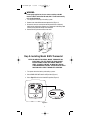
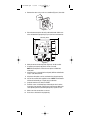
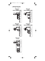
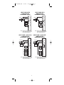
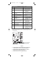
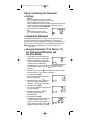
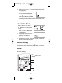
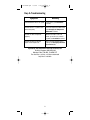
110-1090B.qxd
3/4/05
3:58 PM
Page 1
8425
®
NeW
DIGITAL
NON-PROGRAMMABLE
THERMOSTAT
G
E
O
H
GAS
ELECTRIC
OIL
HEAT PUMP
2 Heat / 2 Cool
User's Manual
Quick Start
Installation
110-1090B
Application
The Robertshaw 8425 is a multi-stage thermostat designed to control
24 VAC heat pump systems.
Features
• Large backlit display
• Adjustable 1st stage temperature differential: 1.0°F to 3.0°F (0.5°C to
1.5°C)
• Adjustable 2nd stage temperature differential: 1.0°F to 6.0°F (0.5°C to
3.0°C)
• Adjustable 2nd stage delay (10-40 minutes)
• Compressor short cycle protection
• Accuracy within ±1°
• Zone system compatible as a master thermostat
• Permanent memory retention
• Fahrenheit/Celsius display option
• Adjustable from 45°F to 90°F (7°C - 32°C)
• Quick wire terminal block
1
110-1090B.qxd
3/4/05
3:58 PM
Page 2
! WARNING:
• Always turn off power at main fuse or circuit breaker panel before
installing, removing, cleaning, or servicing thermostat.
• Read all the information in this manual before installing this thermostat.
• DO NOT CONNECT TO 120 VAC. This is a 24 VAC low-voltage
thermostat. Do not install on voltages higher than 30 VAC.
• All wiring must conform to local and national building and electrical
codes and ordinances.
• Do not short (jumper) across terminals on the gas valve or at the
system control to test installation. This will damage the thermostat
and void the warranty.
• Do not connect ground to any terminal in this unit.
Recycling Thermostat
If this thermostat REPLACES a thermostat that contains mercury,
DO NOT discard the old thermostat in the regular trash. Mercury
is harmful to humans and the environment. For this reason, do
not open, break, or crush the mercury cell. If mercury leaks from
a damaged cell, DO NOT touch or handle mercury with bare
hands. Use protective, non-absorbent gloves to place mercury
into a sealable container. Fill the container with sand or another
absorbent material and seal the container completely.
Return the mercury or mercury products, in a sealed container, to
Invensys Controls Americas or a local recycling center for proper
disposal. If you have any questions, call Robertshaw technical
support at 1-800-445-8299.
Invensys Controls Americas
28C Leigh Fisher Blvd.
El Paso, TX 79906
Attn: Mercury Recycling Center
Step 1: Replacing Existing Thermostat
Wiring Table
Old Terminal
New Label
R, V-VR or VR-R
R
24VAC, return
Y, Y1, M
Y1
Compressor relay (Stage 1)
O or R
O
Reversing valve (cool active)
B
B
Reversing valve (heat active)
F or G
G
Fan control relay
Y2
Y2
2nd stage cooling circuit
W2, W-U or E
Description
W2/E
2nd stage heating control or
emergency heating for heat pumps
C, X or B
C
24 VAC, transformer common side
L or X
L
System monitor
W or W1
W1
1st stage heat - non heat pump
NOTE: THIS THERMOSTAT REQUIRES A 24 VAC COMMON WIRE FOR PROPER OPERATION.
NOTE: ON SOME OLDER MODELS, THE C TERMINAL CAN BE EITHER THE COOLING CONTROL OR
THE COMMON SIDE OF THE TRANSFORMER. CHECK FURNACE WIRING DIAGRAM TO VERIFY C
TERMINAL. IF IT IS THE COMMON SIDE OF THE TRANSFORMER, CONNECT TO THE C TERMINAL.
2
110-1090B.qxd
3/4/05
3:58 PM
Page 3
! WARNING:
In heat pump applications, do not connect anything to the W1
terminal. When switched to HP mode, W1 is connected internally
to Y1 on the thermostat.
1. Turn off power to heating and cooling system.
2. Remove cover from old thermostat to expose wires (Figure 1).
3. Disconnect wires one at a time from existing terminals. Use enclosed
labels to mark existing wires. Refer to cross references in the Wiring Table
if existing wiring does not directly match the labels.
4. Remove existing thermostat base from wall.
Figure 1
Step 2: Installing Model 8425 Thermostat
NOTE: FOR NEW INSTALLATIONS, MOUNT THERMOSTAT ON
INSIDE WALL, FIVE FEET ABOVE THE FLOOR. DO NOT
INSTALL BEHIND A DOOR, IN A CORNER, NEAR AIR
VENTS, IN DIRECT SUNLIGHT, OR NEAR ANY HEAT OR
STEAM GENERATING FIXTURES. INSTALLATION AT THESE
LOCATIONS WILL AFFECT THERMOSTAT OPERATION.
1. Turn power off to the heating and cooling systems.
2. Place EMER-HEAT-OFF-COOL in OFF position (Figure 2).
3. Place
AUTO-ON switch into AUTO position (Figure 2).
emer heat off cool
auto on
°
F
emer heat off cool
auto on
°
F
Figure 2
3
110-1090B.qxd
3/4/05
3:58 PM
Page 4
4. Remove the cover using a coin or screwdriver (Figure 3). Set aside.
auto
off
heat
on
cool
°
F
MON
set
p vac clock
t temld hold
ho
run/se
prog
Figure 3
5. Place thermostat against the wall at desired location. Make sure
wires will feed through opening (Figure 4) on base of thermostat.
Mounting Holes
°
F
C
Y2
R
W2/E
L
G
O
B
Y1
W1
NON_HP HP
ELEC GAS
Figure 4
6. Mark placement of mounting holes (Figure 4). Set base aside.
7. If mounting on drywall, tap plastic anchors into wall.
NOTE: Enclosed plastic anchors do not require a drilled hole
for drywall.
8. If mounting on a surface other than drywall, drill the marked holes
using a 3/16" (5mm) drill bit.
9. Align base with plastic anchors and feed wires through opening.
10. Secure base to wall with supplied screws. NOTE: The thermostat
will mount horizontally on a single gang junction box.
11. Strip end of wires 5/16” (8mm) if needed.
12. Terminal screws are already loose and ready for wire insertion.
Insert wires into terminal strip (Figure 4) matching the label to the
corresponding terminal (see Wiring Diagrams). Tighten screws.
13. Make sure wire connections are secure.
14. Push excess wire back through opening.
4
110-1090B.qxd
3/4/05
3:58 PM
Page 5
♦ Wiring Diagrams
HEAT ONLY
3-WIRE
SINGLE TRANSFORMER
HEAT/COOL
4-WIRE
SINGLE TRANSFORMER
R
Transformer
Hot
120 VAC
C
24 VAC
Heating
Control
W1
Cooling
Control
Y1
Fan
Control
G
O
R
T
H
E
R
M
O
S
T
A
T
Transformer
C
Hot
120 VAC
24 VAC
Heating
Control
Y1
Fan
Control
B
Y2
Y2
W2/E
W2/E
COOL ONLY
3-WIRE
SINGLE TRANSFORMER
HEAT ONLY
2-WIRE
SINGLE TRANSFORMER
R
C
Hot
120 VAC
24 VAC
Heating
Control
W1
Y1
G
O
B
Y2
G
O
B
Transformer
W1
R
Transformer
T
H
E
R
M
O
S
T
A
T
C
Hot
120 VAC
24 VAC
W1
Cooling
Control
Fan
Control
Y1
G
O
B
Y2
W2/E
W2/E
HEAT/COOL
2 STAGE
R
Transformer
Hot
120 VAC
C
24 VAC
L
First Stage
Heat
W1
First Stage
Cool
Y1
B
O
Fan
Control
G
Second
Stage Cool
Y2
Second
Stage Heat
W2/E
T
H
E
R
M
O
S
T
A
T
T
H
E
R
M
O
S
T
A
T
5
T
H
E
R
M
O
S
T
A
T
110-1090B.qxd
3/4/05
3:58 PM
Page 6
HEAT PUMP WITH
COOL ACTIVE
REVERSING VALVE
R
Transformer
C
Hot
24 VAC
120 VAC
W1
Compressor
Contactor
Y1
Fan
Relay
G
Reversing
Valve
O
B
HEAT PUMP WITH
HEAT ACTIVE
REVERSING VALVE
R
T
H
E
R
M
O
S
T
A
T
Transformer
C
Hot
24 VAC
120 VAC
W1
Compressor
Contactor
Y1
Fan
Relay
G
O
Reversing
Valve
Y2
Y2
W2/E
W2/E
NOTE: Make sure the HP swtich is in the HP
position. When switched to HP mode,
W1 is connected internally to Y1.
NOTE: Make sure the HP swtich is in the HP
position. When switched to HP mode,
W1 is connected internally to Y1.
HEAT PUMP + AUX COOL
COOL ACTIVE
REVERSING VALVE
R
Transformer
Hot
120 VAC
C
24 VAC
L
Compressor
Fault Output
(24VAC)
W1
Compressor
Contactor
Y1
B
Reversing
Valve
Fan
Control
O
B
T
H
E
R
M
O
S
T
A
T
HEAT PUMP + AUX HEAT
HEAT ACTIVE
REVERSING VALVE
T
H
E
R
M
O
S
T
A
T
R
Transformer
Hot
120 VAC
C
24 VAC
L
Compressor
Fault Output
(24VAC)
W1
Compressor
Contactor
Y1
Reversing
Valve
B
O
G
Fan
Control
Second
Stage Cool
Y2
Second
Stage Cool
Y2
Aux/Emer
Heat
W2/E
Aux/Emer
Heat
W2/E
NOTE: Make sure the HP swtich is in the HP
position. When switched to HP mode,
W1 is connected internally to Y1.
6
T
H
E
R
M
O
S
T
A
T
G
NOTE: Make sure the HP swtich is in the HP
position. When switched to HP mode,
W1 is connected internally to Y1.
110-1090B.qxd
3/4/05
3:58 PM
Page 7
TERMINAL LEGEND - 8425
TERM
REQ?
TERMINAL FUNCTION
R
24 VAC hot connection
EQUIPMENT TO CONNECT
Yes
C
24 VAC common connection
Yes
L
System fault indicator
connection
First stage connection for
non heat-pump applications
Second stage cooling
connection
First stage compressor
connection
No
For input of 24VAC hot
side of transformer
For input of 24VAC
common side of
transformer
For connection of system
fault indicator (if present)
Energizes on a call
for heat
Energizes on a call for
second stage cooling
Energizes on a call for
first stage of heating
and cooling
Energizes on a call for
second stage or
emergency heat
Energizes when in the
HEAT or EM modes
Energizes when in the
COOL mode
Energizes with E & Y1, Y2
and W2 terminals or with
FAN option switched to
the ON position
W1
Y2
Y1
No*
No
Yes
W2/E Second stage heat or
Emergency heat connection
Yes*
B
Yes**
Heat active reversing
valve connection
Cool active reversing
valve connection
Indoor fan connection
O
G
Yes**
Yes
* Do not connect W1 in heat pump applications. Connect auxiliary heat to W2/E.
** Most heat pump systems will have a cool active or a heat active reversing valve. Use the
appropriate terminal.
°
F
C
Y2
R
W2/E
L
G
O
B
Y1
W1
NON_HP HP
ELEC GAS
HP OPTION SWITCH
Heat pump switch.
ELECTRIC/GAS SWITCH
Selects fan control.
Figure 5
15. Set the Electric/Gas switch to either GAS for a gas/oil heating
system or ELEC for an electric heating system (Figure 5).
16. Set the HP option switch to either the HP for heat pump or
NON_HP for furnace applications (Figure 5).
17. Replace thermostat cover by snapping into place.
7
110-1090B.qxd
3/4/05
3:58 PM
Page 8
Step 3: Testing the Thermostat
! WARNING: DO NOT SHORT (JUMPER) ACROSS TERMINALS OF GAS
VALVE OR SYSTEM CONTROL TO TEST OPERATION. THIS WILL
DAMAGE THE THERMOSTAT AND VOID YOUR WARRANTY.
CAUTION: DO NOT SWITCH SYSTEM TO COOL OR LEAVE IN COOL MODE
IF THE TEMPERATURE IS BELOW 50°F (10°C). THIS CAN
DAMAGE THE AIR CONDITIONING SYSTEM AND CAUSE PERSONAL INJURY.
1. Place the EMER-HEAT-OFF-COOL switch into
the COOL position. The will be displayed.
emer heat off cool
2. Press the button until the temperature
setting is at least 3 degrees below the room temperature. The air
conditioning system should turn on within a
few seconds.
NOTE: ONCE THE THERMOSTAT TURNS OFF WHEN IN THE COOL MODE,
A BUILT IN 5-MINUTE DELAY PREVENTS THE SYSTEM FROM
TURNING ON AGAIN. THIS PROTECTS THE COMPRESSOR. NO
ADDITIONAL TIME DELAY RELAY IS REQUIRED. TO OVERRIDE THE
5-MINUTE DELAY FOR INSTALLATION, PRESS THE RESET BUTTON.
3. Put the EMER-HEAT-OFF-COOL switch into the
OFF position. The air conditioning system
should turn off.
emer heat off cool
4. Put the EMER-HEAT-OFF-COOL switch into the
HEAT position. The will be displayed.
5. Press the button until the temperature
emer heat off cool
setting is at least 3 degrees above room
temperature. The heating system should turn on. The fan may
not turn on immediately, depending on the fan delay built into
the furnace.
NOTE: If HP is selected, the heat will not come on until the 5 minute
short cycle protection has expired.
6. Put the EMER-HEAT-OFF-COOL switch into the
EMER position. The
will be displayed.
emer heat off cool
7. Press the button until the temperature
setting is at least 3 degrees above room
temperature. The secondary heating system should turn on.
NOTE: The compressor will not turn when in
emergency heat mode.
8. Put the EMER-HEAT-OFF-COOL switch into the
OFF position. The heating system should turn emer heat off cool
off. The fan may continue to run for a short
period of time.
9. Put the
AUTO-ON switch into the ON position.
The blower fan should turn on. The display will show
a
.
10. Put the
AUTO-ON switch into the AUTO position.
The blower fan should turn off.
8
auto on
auto on
110-1090B.qxd
3/4/05
3:58 PM
Page 9
Step 4: Customizing the Thermostat
♦ Settings
System
Cool: The thermostat controls the cooling.
Off: The heating and cooling systems are off.
Heat: The thermostat controls the heat.
Emer:The thermostat controls the second stage emergency heat. Use
only when the primary stage of heat is not functioning or requires
service. The display will show CHECK HP
when the heat pump requires service.
Fan
Auto: Equipment controls the fan.
On: The fan operates continuously.
♦ Temperature Differential
The temperature differential for 1st stage is factory set at 1.0°F (.5°C).
This means that whenever the room temperature changes by one
degree Fahrenheit from the temperature setting, the system will turn on.
If the system turns on too often, increase the temperature differential.
NOTE: The temperature differential for 2nd stage is factory set at
2.0°F (1.0°C)
♦ Changing Fahrenheit (°F) to Celsius (°C),
the Temperature Differential, and
the Filter Monitor
1. The thermostat is preset to display the
temperature in degrees Fahrenheit (US
models) or degrees Celsius (Canadian
models). The temperature display can be
changed. Press and hold both the
and buttons for three seconds. The display will flash either
an F or C. Release buttons. Press the or button to switch
the display.
2. Wait five seconds or press
and the display will switch to the differential setting for 1st stage heating and cooling.
3. The display will read diFF.
Press the or button to adjust the
differential up or down.
4. Wait five seconds or press
and the
display will switch to the differential
setting for 2nd stage heating and cooling.
5. The display will read diF2.
Press the or button to adjust the differential up or down.
6. Wait five seconds or press
and
the display will switch to the
differential delay.
7. The display will read dLY2.
The differential delay is the length of time
(in minutes) from when the 1st stage
engages, until the 2nd stage engages to
assist in heating or cooling. Press the or
button to adjust the delay up or down.
9
110-1090B.qxd
3/4/05
3:58 PM
8. Wait five seconds or press
ter monitor setting.
Page 10
and the display will switch to the fil-
9. CHECK FILTER and the length of hours for
the filter monitor will be displayed.
10. Use the or to adjust the filter timer
from 0 (OFF) to 9900 hours. NOTE: The
filter timer is based on equipment run
time. Select the length of time based on the recommended service
interval for your filter.
11. Press the
to return to normal operation.
♦ Check Filter Reset
Once the filter timer has expired,
CHECK FILTER will turn on and stay
on. To clear the message and reset
the timer:
1. Press the and buttons and
hold for 3 seconds. CLr will appear
in the time display.
2. Press any key to clear the message.
The display will transition to the
temperature scale display as
described in the previous section.
3. No further input is needed. Within a few seconds, the display will
return to the normal operating mode.
♦ Backlit Display
This thermostat is equipped with a backlight to make night time temperature adjustments quick and easy. Press the
button to activate the
backlight. The backlight will turn off after about 10 seconds of inactivity.
♦ Reset
To reset the thermostat press the RESET button located above the upper
left corner of the display.
RESET switch
°
F
C
Y2
R
W2/E
L
G
O
B
Y1
W1
NON_HP HP
ELEC GAS
10
110-1090B.qxd
3/4/05
3:58 PM
Page 11
Step 5: Troubleshooting
Symptom
Remedy
Thermostat does not turn on system.
Check wiring (see Installation
section).
Thermostat turns system on and
off too frequently.
Increase temperature differential
(see Changing the Temperature
Differential section).
System fan does not operate
properly.
Move Electric/Gas switch to
either gas or electric, to match
system (see Installation section).
Thermostat does not display
proper room temperature.
Check F/C (Fahrenheit/Celsius)
setting. See Changing Fahrenheit
(F) to Celsius (C).
If problems with thermostat cannot be resolved, call:
Technical Support: (800) 445-8299
Monday-Friday 7:30 AM - 5:30 PM CST
For after hours service, a 24-hour automated
help line is available.
11
110-1090B.qxd
3/4/05
3:58 PM
Page 12
Two Year Limited Warranty
Invensys Controls Americas warrants to the original contractor
installer, or to the original consumer user, each new Robertshaw
thermostat to be free from defects in materials and workmanship under
normal use and service for a period of two (2) years from date of
purchase. This warranty and our liability does not apply to batteries or
merchandise that has been damaged by misuse, neglect, mishandling,
alterations, improper installation, or use in a way other than in
accordance with Invensys Controls Americas recommendations
and instructions.
Invensys Controls Americas agrees to repair or replace at its option any
thermostat under warranty provided it is returned within the warranty
period, postage prepaid, with proof of the date of purchase. Cost of
thermostat removal or reinstallation is not the responsibility of Invensys
Controls Americas.
Repair or replacement as provided under this warranty is the exclusive
remedy of the consumer. Invensys Controls Americas shall not be liable
for any incidental or consequential damages for breach of any express
or implied warranty on this product, or under any other theory of liability.
Except to the extent prohibited by applicable law, any implied warranty
of merchantability or fitness for a particular purpose on this product is
limited to the duration of this warranty.
Some states do not allow the exclusion or limitation of incidental or
consequential damages, or allow limitations on how long an implied
warranty lasts, so the above limitations or exclusions may not apply to
you. This warranty gives you specific legal rights, and you may also have
other rights which vary from state to state.
For warranty returns, send thermostat, shipping prepaid to:
Invensys Controls Americas
Warranty Claims Department
515 S. Promenade
Corona, CA 92879-1736
Controls Americas
191 E. North Avenue
Carol Stream, Illinois 60188
United States of America
©2005 Invensys Controls Americas
110-1090B
12