1
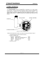
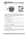
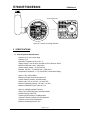
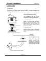
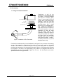
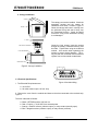
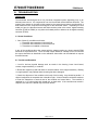
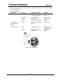
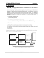
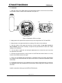
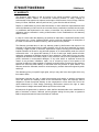
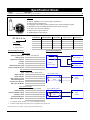
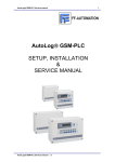
INSTALLATION, OPERATION
AND MAINTENANCE MANUAL
FOR
E7000, E7500, AND E8000
4 TO 20 mA ANALOG TRANSMITTERS
3255 W. STETSON AVENUE
HEMET, CA 92545-7799
Tel (951) 652-6811 • Fax (951) 652-3078
www.mccrometer.com
E7000/E7500/E8000
IOM Manual
Table of Contents
Topic
Page
I. GENERAL INFORMATION ________________________________________________________ 2
A. UNPACKING AND INSPECTION ________________________________________________________ 2
B. PRECAUTIONS____________________________________________________________________ 3
C. DESCRIPTION ____________________________________________________________________ 3
1. General ______________________________________________________________________ 3
2. Totalizer Output Circuit _________________________________________________________ 4
3. Switch Selected Scale Output_____________________________________________________ 4
II SPECIFICATIONS________________________________________________________________ 5
A. OVERALL SYSTEMS SPECIFICATIONS __________________________________________________ 5
III. INSTALLATION_________________________________________________________________ 6
A. DISASSEMBLY ___________________________________________________________________ 6
1. Canopy Removal _______________________________________________________________ 6
2. Register Removal ______________________________________________________________ 6
B. RE-ASSEMBLY ___________________________________________________________________ 7
1. Analog Transmitter Installation ___________________________________________________ 7
2. Canopy Installation_____________________________________________________________ 8
C. ELECTRICAL SPECIFICATIONS________________________________________________________ 8
IV. TROUBLESHOOTING __________________________________________________________ 10
A. NORMAL CONDITIONS ____________________________________________________________ 10
B. TROUBLES AND REMEDIES _________________________________________________________ 10
V. CALIBRATION _________________________________________________________________ 12
A. PREPARATION __________________________________________________________________ 12
B. CALCULATIONS _________________________________________________________________ 12
C. CALIBRATION ___________________________________________________________________ 13
VI. WARRANTY ___________________________________________________________________ 14
© 1996-2007 by McCrometer, Inc.
Printed in U.S.A.
Lit# 24512-00 Rev. 1.6/07-07
E7000/E7500/E8000
IOM Manual
I. GENERAL INFORMATION
A. Unpacking and Inspection
Your E7000/E7500/E8000 ANALOG TRANSMITTER is engineered to be a highly reliable,
accurate system. It has been systematically assembled, inspected, tested and calibrated; then
carefully packed or installed on your new McCrometer flowmeter before shipment. If not
installed, unpack the transmitter carefully and inspect each assembly thoroughly for obvious
shipping damage (Figure 1). Notify the freight carrier immediately upon discovery of any
damage.
CIRCUIT BOARD
MAGNET ASSEMBLY
CONDULET
ALUMINUM HOUSING
Figure 1. E7000 Transmitter shown
Make sure that all parts are included in the shipment listed below and shown in figure 2.
1. E7000/E7500/E8000 Analog Transmitter Assembly
2. EH222-10 Installation Kit:
EH221-00
Cable Extension
10142-20
Screw 10-32 x 3” Long w/ Seal Hole
10142-30
Screw 10-32 x 2-3/4” Long
10180-00
O-Ring 3-5/8” OD
10262
Gasket Flat
3. Specification Sheet
1 each
1 each
5 each
1 each
1 each
Page 2 of 14
© 1996-2007 by McCrometer, Inc.
Printed in U.S.A.
Lit# 24512-00 Rev. 1.6/07-07
E7000/E7500/E8000
IOM Manual
FLAT GASKET
O-RING
CABLE EXTENSION
SCREWS
HOUSING
Figure 2. E7000/E7500/E8000 Retrofit Parts Kit
B. Precautions
Avoid rough handling of the transmitter. The electronic circuits are of solid state technology but
damage can result from shock in a fall. During unpacking and installation avoid dusty areas as
much as possible. Fine dust or sand can cause erratic operation or failure of the circuitry.
Once installed properly, the transmitter assembly is nearly impervious to environmental effects.
When connecting the cables and connectors, be sure that the screws are securely fastened and
that the connectors are firmly pressed into place. Normally, you will not have to be concerned
with the internal connections unless you are performing maintenance on the assembly.
Double check the installation, wiring, and power supply used to excite the transmitter to ensure
that specifications are adhered to properly and precisely to avoid failure and violation of
warranty.
C. Description
1. General
The transmitter is a single assembly mounted on the flowmeter beneath the register assembly.
It is contained in an aluminum housing 4.25" in diameter and approximately 2" high. It comes
equipped with a standard 1/2" electrical LL19 condulet attached by a brass 1/2" close nipple.
The transmitter uses the mechanical rotation of the flexible drive shaft to turn a magnet
assembly generating an electric pulse. The pulse is generated by a rotating magnet assembly
that has four or eight magnets placed evenly around the assembly.
Page 3 of 14
© 1996-2007 by McCrometer, Inc.
Printed in U.S.A.
Lit# 24512-00 Rev. 1.6/07-07
E7000/E7500/E8000
IOM Manual
SENSORS
MAGNET ASSEMBLY
Figure 3. Location of Magnets and Sensors
The magnets pass by the sensor (Figure 3) or sensors depending on whether you have the
standard E7000 (one sensor), the anti-reverse E7500 (two sensors), or the forward/reverse
E8000 transmitter, and in doing so the magnet generates a pulse output that either goes to a
digital-to-analog converter circuitry (standard), or to the quadrature IC (for anti-reverse) and
then to the digital-to-analog converter circuitry.
2. Totalizer Output Circuit
With the E7000/E7500 there are two totalizer output options. These options must be ordered
when the transmitter is manufactured.
1. The DRY CONTACT output.
This is an internal relay rated at .5 Amps. resistive, 125 VAC, 1 Amp 30 VDC.
2. The optically isolated NPN transistor output.
The end user supplies the power (up to 40 VDC) and ground to the open collector
output.
NOTE: The E8000 provides forward and reverse 4-20 mA output, but pulse output in one
direction only (specified at time order).
The pulse output from the Totalizer varies with different pipe sizes. When using the RELAY
option the transmitter is limited to under 10 pulses per minute, when using the OPEN
COLLECTOR output you can achieve a much greater pulse rate, up to 700 pulses per minute.
3. Switch Selected Scale Output
The totalizer output can be reprogrammed in the field. What this means is that the amount of
fluid that passes through the meter before one totalizer pulse can be changed by simply
changing the switch settings on the board shown in Figure 4. Contact McCrometer if the
totalizer scaled pulses will be set to a different value.
Page 4 of 14
© 1996-2007 by McCrometer, Inc.
Printed in U.S.A.
Lit# 24512-00 Rev. 1.6/07-07
E7000/E7500/E8000
IOM Manual
SCALING SWITCHES
Figure 4. Location of Scaling Switches
II SPECIFICATIONS
A. Overall Systems Specifications
Accuracy: 0.5% over entire range
Linearity: 0.1%
Operation Temperature: 25 to 130 ° F
Supply Voltage: 16 to 40 VDC, Nominal 24 VDC, Minimum 25mA
Maximum Resistive Load = 1200 Ohms
(Power Supply Voltage - 16 VDC)/20 mA
Example: (40 VDC - 16 VDC)/20 mA = 1200 Ohms
Temperature Coefficient: +/- 1% Over Entire Temperature Range
Option 1, Dry Contact Relay
Maximum Contact Closures per Minute:10
Contact Closure Duration: 20 milliseconds
Rated Load: 0.5 A at 125 VAC, 1 A at 30 VDC
Maximum Operating Voltage: 125 VAC, 110 VDC
Maximum Switched Power: 30W, 62.5 VA
Option 2, Optically Isolated Transistor
Output Type: NPN Darlington, Optically Isolated
Isolation Voltage: 5000 Vac
Totalizing Pulse Duration: 20 Milliseconds
Collector to Emitter Voltage: 40 VDC Maximum
Collector Current: 200 mA Maximum
Maximum Pulses per Minute: 350
Page 5 of 14
© 1996-2007 by McCrometer, Inc.
Printed in U.S.A.
Lit# 24512-00 Rev. 1.6/07-07
E7000/E7500/E8000
IOM Manual
III. INSTALLATION
A. Disassembly
It is necessary to remove the existing canopy and register. The analog transmitter mounts
between the register and the register mounting plate already installed on top of the pipe
protruding from the top of the meter.
* Note: If your meter has the old style plastic canopy and gasket you must replace both the
canopy and the base plate with new aluminum
ones (Order Canopy Kit RO143-00).
THE FLOWMETER CAN BE IN FULL
OPERATION DURING THIS PROCEDURE
1. Canopy Removal
CANOPY
Remove the six (6) screws holding the
Canopy to the mounting plate and discard,
Figure 5. One of the screws has a seal
attached, remove it prior to removing that
screw. Lift off the canopy carefully to prevent
damage to the register.
MECHANICAL REGISTER
2. Register Removal
PAL NUT
Loosen the pal nut located on the threaded
shaft of the register. Carefully unscrew the
register counter clockwise and lift it from the
bushing.
MOUNTING PLATE
Figure 5. Canopy, Register Removal
CAUTION:
Protect the Register from dust while it is outside of the Canopy.
DRIVE CABLE
You can now see the open
end of the ELL with the drive
cable, Figure 6. If the
flowmeter is in operation the
cable will be rotating. If the
flowmeter is not installed turn
the propeller by hand to check
that the bearing and cable
rotate freely with no excess
play.
Figure 6. Location of The Drive Cable
Page 6 of 14
© 1996-2007 by McCrometer, Inc.
Printed in U.S.A.
Lit# 24512-00 Rev. 1.6/07-07
E7000/E7500/E8000
IOM Manual
B. Re-assembly
1. Analog Transmitter Installation
E7000 TRANSMITTER
O - RING
FLAT GASKET
MOUNTING PLATE
Figure 7. Installation Of The Transmitter
Cleanliness is vital for the
operation of the transmitter and
the register. Check the threaded
area and the mounting plate,
Figure 7, they should be free of
grease, dust, or any other foreign
materials. Place the o-ring and
flat gasket over the lip on the
mounting plate. Use a small
amount of oil to lubricate the oring. Rotate the transmitter to
align and locate the condulet to
the desired position. Lower the
transmitter to insert the cable
into the center shaft of the
transmitter. Continue to lower the
unit until it touches the o-ring on
the Plate. Work the transmitter
carefully down over the o-ring,
seat it firmly into place. Avoid unnecessary movement to prevent
damage to the o-ring.
Find the short cable extension in the installation kit and insert it into the center of the bearing
on top of the transmitter. Place the register with the Pal nut still in place on this cable
extension and rotate it clockwise three (3) or four (4) turns. Stop when the register is
positioned as it was prior to its' removal and snug up the pal nut. If the flowmeter is operating
turn register in until there is a slight binding of the cable in the Register and back out
approximately two (2) turns and then tighten the Pal nut; this should give you smooth
operation and be correctly positioned.
Page 7 of 14
© 1996-2007 by McCrometer, Inc.
Printed in U.S.A.
Lit# 24512-00 Rev. 1.6/07-07
E7000/E7500/E8000
IOM Manual
2. Canopy Installation
CANOPY
The canopy can now be installed. Check the
transmitter housing and the canopy for
cleanliness and clean if needed, Figure 8.
Orient the canopy and lower it carefully over
the lubricated o-ring and seat it firmly onto
the Transmitter Housing. Again, be careful
so that the o-ring on the transmitter housing
is not damaged.
SCREW
O - RING
Locate the long screws; insert the screws
through the canopy, transmitter housing, and
the Plate. Tighten them using the crisscross
method. Use caution when tightening the
screws to prevent thread damage. The oring will seal the transmitter and mechanical
register from environmental contaminants.
MECHANICAL REGISTER
E7000 TRANSMITTER
MOUNTING PLATE
Figure 8. Canopy Installation
C. Electrical Specifications
Figure 9.Condulet Wiring
1. The Electrical Requirements are:
a. 16-40 VDC
b. 20 mAdc minimum per 4-20 mA loop
2. Remove the cover from the condulet and observe the wires connected to the terminal strip,
Figure 9.
The color codes are as follows:
a.
b.
c.
d.
Black = RETURN positive 4-20 mA out
Red = Positive (+) 16-40 VDC from external power
Orange = Positive collector (collector output), or relay contact (normally open)
Blue = Negative emitter (collector output), or relay contact (common)
Page 8 of 14
© 1996-2007 by McCrometer, Inc.
Printed in U.S.A.
Lit# 24512-00 Rev. 1.6/07-07
E7000/E7500/E8000
IOM Manual
3. Connect the external power and loads to the terminals in the condulet as follows:
a. Connect the positive (+) lead from the external power supply to the terminal with the RED
wire connected inside the condulet, and the negative (-) side of the power supply to the
negative side of the LOAD, then connect a wire from the Positive side of the LOAD to the
BLACK wire inside the condulet as shown in Figure 10.
16 - 40 VDC
POWER
SUPPLY
BLACK
RED
LOAD
INSTRUMENTATION
BLACK
BLUE
ORANGE
COLLECTOR
OPTICALLLY
ISOLATED
OUTPUT
EMITTER
OR
RELAY
OUTPUT CONTACTS
Figure 10.Electrical Connections
b. For scaled pulse output (e.g. 1P=100 gal) use the ORANGE and BLUE wires, depending on
what option that you ordered. The ORANGE wire will be either the Collector output or the
Normally Open output. And the BLUE wire will be either the Emitter or the Common output.
Page 9 of 14
© 1996-2007 by McCrometer, Inc.
Printed in U.S.A.
Lit# 24512-00 Rev. 1.6/07-07
E7000/E7500/E8000
IOM Manual
IV. TROUBLESHOOTING
OPERATION
The transmitter was designed as a fully functional integrated system depending only on an
external power source. It is composed of one circuit board with several different functions. The
magnet drum rotates on the shaft, which passes by the sensor that produces a pulse which is
then transformed into a square wave and goes to the directional sensor. Depending on what
model you have, the directional sensor will either send the pulse to the correct digital-to-analog
converter (E7000 or E8000) or only allow the forward pulses to advance to the digital-to-analog
converter (E7500).
A. Normal Conditions
1. One of three (3) conditions could exist:
1. Flowmeter with transmitter in line with flow.
2. Flowmeter with transmitter in line without flow.
3. Transmitter not installed on flowmeter
In any of the conditions above the outputs with the magnet rotating at a known speed (RPM)
should be at a predicted level. The 4-20 mAdc output should be a steady level of current and
the output should be as described on the calibration sheet which can be obtained on request
from McCrometer.
B. Troubles and Remedies
1. Look for obvious physical damage such as cracks in the housing, loose circuit board,
screws, magnet assembly, or condulet.
2. Rotate the magnet by hand and check for smooth rotation of the magnet assembly. Binding
or rough operation may indicate that the bearing has been damaged.
3. Check the alignment of the condulet to the body of the housing, they should be parallel. A
slight mis-alignment is acceptable but it should be tight. A loose condulet could allow moisture
to enter the transmitter or terminal area of the condulet and cause failure. The condulet is
attached by a 1/2" close nipple with thread lock on both ends. If the condulet was moved in
shipment, the seal of the thread may have been broken.
Page 10 of 14
© 1996-2007 by McCrometer, Inc.
Printed in U.S.A.
Lit# 24512-00 Rev. 1.6/07-07
E7000/E7500/E8000
IOM Manual
Table 1 has a list of conditions, things to check, possible causes of the troubles, and what to do
to correct the problems.
Table 1. Troubleshooting
CONDITION
CHECK
No output
Power supply.
POSSIBLE CAUSE
Wrong power supply.
or faulty power supply
REMEDY
Replace power
supply
Check AC
power at
Source
Power supply not
plugged in or no
power to power supply
Plug in power
supply to AC at
Source
16 - 40 VDC to
transmitter but no
outputs
Wiring
Loose or disconnected
Wire(s)
Fix Wire(s)
Incorrect Output
Load
Load Exceeds limit
Magnet
Magnet Assembly Set
Screw Loose
Decrease Load
Resistance (RL)
Tighten Set
Screw
LOOSE WIRING
MAGNET SET SCREW
Figure 12 Troubleshooting
Page 11 of 14
© 1996-2007 by McCrometer, Inc.
Printed in U.S.A.
Lit# 24512-00 Rev. 1.6/07-07
E7000/E7500/E8000
IOM Manual
V. CALIBRATION
IMPORTANT: Allow the mA output to stabilize for 1-2 minutes when the unit is first powered up
before reading or changing output values.
It is necessary that you be able to rotate the magnet in the transmitter at a controlled rate and
read the current output. The following list of equipment is meant as a reference only, but is the
equipment we use in our electronics department at McCrometer. You may use any desired test
equipment as long as it has the accuracy and you know the RPM-s applied. Your calibration is
only as good as the equipment used and the skill and knowledge of the Technician. If you lack
the necessary equipment to calibrate the transmitter, it can be sent to McCrometer for
calibration.
1. Fluke 8060A Digital Multimeter
Used to measure milliamps
2. A known controlled means of rotating the magnet.
Minarik Electric (818) 507-6500 has quality equipment and a variety from which
to choose. (MM21111A - DC Speed Control, 504-00-042 - Rae 1/50HP DC Motor)
A. Preparation
1. Refer to Set Up drawing, Figure 13 and connect the equipment accordingly.
2. Calculate the required motor speed and the corresponding current reading.
3. Ensure that the motor turns the mechanical linkage clockwise when looking at the top of
the transmitter.
B. Calculations
Attached to each transmitter is a label showing a full scale propeller RPM. Set the motor at that
speed to adjust the current output to 20 mAdc.
SPEED
CONTROLLER
MOTOR
MULTIMETER
24 VDC
POWER
SUPPLY
MECHANICAL
LINKAGE
TOP OF
TRANSMITTER
RED
BLACK
Figure 13 Block Diagram of Calibration Set Up
Page 12 of 14
© 1996-2007 by McCrometer, Inc.
Printed in U.S.A.
Lit# 24512-00 Rev. 1.6/07-07
E7000/E7500/E8000
IOM Manual
C. Calibration
1. With the motor at zero RPM, adjust the potentiometer farthest to the left end of the E7000
circuit board to read 4.0 mAdc on the multimeter, see Figure 14.
ZERO
SPAN
Figure 14 Calibration Of Zero and Span
2. Apply power to the speed control system that you are using and set for Full Scale RPM.
3. Adjust the pot on the right hand side for a reading of 20 mAdc on the multimeter.
4. Stop the rotation of the magnet and check the 4 mAdc reading. It may take a minute or
two to stabilize; check and if necessary re-adjust the left potentiometer to obtain the 4 mAdc
reading on the multimeter.
5. You may have to repeat the zero and span adjustments two or three times to be sure that
the adjustments are stable.
6. Reverse the motor direction to verify function of the E7500 anti-reverse feature or to verify
function of the E8000 reverse mA output.
7. Once you are satisfied that the transmitter is calibrated properly and within specifications
the equipment can be disconnected from power and stored in a clean and temperature stable
environment.
8. A suggestion at this point in your calibration is to put a drop of fingernail polish, or enamel on
the adjustment end of the potentiometer to prevent them from turning due to vibration from the
flow tubes.
Install the transmitter referring to the INSTALLATION Section.
Page 13 of 14
© 1996-2007 by McCrometer, Inc.
Printed in U.S.A.
Lit# 24512-00 Rev. 1.6/07-07
E7000/E7500/E8000
IOM Manual
VI. WARRANTY
This Warranty Shall apply to and be limited to the original purchaser consumer of any
McCrometer product. Meters or instruments defective because of faulty material or
workmanship will be repaired or replaced, at the option of McCrometer, free of charge, FOB the
factory in Hemet, California, within a period of one (1) year from the date of delivery.
Repairs or modifications by others than McCrometer or their authorized representatives shall
render this Warranty null and void in the event that factory examination reveals that such repair
or modification was detrimental to the meter or instrument. Any deviations from the factory
calibration require notification in writing to McCrometer of such recalibrations or this warranty
shall be voided.
In case of a claim under this Warranty, the claimant is instructed to contact McCrometer, 3255
West Stetson Ave., Hemet, California 92545, and to provide an identification or description of
the meter or instrument, the date of delivery, and the nature of the problem.
The Warranty provided above is the only warranty made by McCrometer with respect to its
products or any parts thereof and is made expressly in lieu of any other warranties, by course
of dealing, usages of trade or otherwise, expressed or implied, including but not limited to any
implied warranties of fitness for any particular purpose or of merchantability under the uniform
commercial code. It is agreed this warranty is in lieu of and buyer hereby waives all other
warranties, guarantees or liabilities arising by law or otherwise. Seller shall not incur any other
obligations or liabilities or be liable to buyer, or any customer of buyer for any anticipated or lost
profits, incidental or consequential damages, or any other losses or expenses incurred by
reason of the purchase, installation, repair, use or misuse by buyer or third parties of its
products (including any parts repaired or replaced); and seller does not authorize any person to
assume for seller any other liability in connection with the products or parts thereof. This
Warranty cannot be extended, altered or varied except by a written instrument signed by seller
and buyer.
This Warranty gives you specific legal rights, and you may also have other rights which vary
from state to state.
McCrometer reserves the right to make improvements and repairs on product components
which are beyond the warranty period at the manufacturer's option and expense, without
obligation to renew the expired warranty on the components or on the entire unit. Due to the
rapid advancement of meter design technology, McCrometer reserves the right to make
improvements in design and material without prior notice to the trade.
All sales and all agreements in relation to sales shall be deemed made at the manufacturer's
place of business in Hemet, California, and any dispute arising from any sale or agreement
shall be interpreted under the laws of the State of California.
Page 14 of 14
© 1996-2007 by McCrometer, Inc.
Printed in U.S.A.
Lit# 24512-00 Rev. 1.6/07-07
Specification Sheet
Model:
Description:
E7000
Two-Wire 4-20 mA Transmitter
Features:
♦ Industry standard 2-wire 4-20 mA output
♦ Output is linear with flowrate
♦ Compatible with all McCrometer propeller meters with a mechanical register
♦ Installation can be accomplished without meter removal from pipe
♦ For meter sizes up to 24”
♦ Signal can travel up to 5000 feet
♦ Additional pulse output and anti-reverse options
E7000-0xx
Anti-Reverse
0 - No
1 - Yes
Pulse Output
0 - None
1 - Dry Contact
2 - Open Collector
E7000 Model:
4-20 mA Output
E7000-000
E7000-001
E7000-002
E7000-010
E7000-011
E7000-012
•
•
•
•
•
•
Electrical Characteristics:
Dry Contact
Open Collector
Anti-Reverse
•
•
•
•
•
•
•
Typical Wiring Diagrams:
4-20 mA Output:
Operating Temperature:
Supply Voltage:
Temperature Coefficient:
Linearity:
Accuracy:
Maximum Resistive Load:
Reverse Voltage Protection:
+25 to +130 degrees F
16 - 40 VDC
±1.0%
0.1%
0.5% over the entire range
Supply Voltage Dependent*
-300V Maximum
Red
Power Supply
Black
E7000
4-20 mA Output
Instrumentation
4-20 mA Input
Dry Contact Output**:
Type:
Rated Load (AC):
Rated Load (DC):
Max. Operating Current:
Max. Switching Power:
Contact Closure Duration:
Max. Clicks per Minute:
Relay Contact, Norm. Open
0.5 A at 125 VAC
1 A at 30 VDC
1A
30 W, 62.5 VA
20 milliseconds
10
Dry Contact Output
Orange
Blue
Pulse
Counter
Open Collector Output**:
Type:
Isolation Voltage:
Collector to Emitter Voltage:
Collector Current:
Pulse Output Duration:
Max. Pulses per Minute:
NPN Darlington, Isolated
5000 VAC
40 VDC Maximum
200 mA Maximum
20 milliseconds
350
Open Collector Output
Orange
Blue
Pulse
Counter
Protection Diode
* - Use formula (Supply Voltage - 16) ÷ 0.02 = Maximum Load(Ω)
** - Totalizer output operates only when power is applied to the 4-20 mA loop.
McCrometer reserves the right to change the Specification without notice.
© 1996-2007 by McCrometer, Inc.
Printed in U.S.A.
Lit# 24512-00 Rev. 1.6/07-07
Specification Sheet
Model:
Description:
E7500
Two-Wire 4-20 mA Transmitter
Features:
♦ Industry standard 2-wire 4-20 mA output, Anti-Reverse
♦ Output is linear with flowrate
♦ Compatible with all McCrometer propeller meters with a mechanical register
♦ Installation can be accomplished without meter removal from pipe
♦ For meter sizes from 24” and above
♦ Signal can travel up to 5000 feet
♦ Additional pulse output options
E7500-01x
E7500 Model:
4-20 mA Output
E7500-010
E7500-011
E7500-012
•
•
•
Pulse Output
0 - None
1 - Dry Contact
2 - Open Collector
Electrical Characteristics:
Dry Contact
Open Collector
Anti-Reverse
•
•
•
•
•
Typical Wiring Diagrams:
4-20 mA Output:
Operating Temperature:
Supply Voltage:
Temperature Coefficient:
Linearity:
Accuracy:
Maximum Resistive Load:
Reverse Voltage Protection:
+25 to +130 degrees F
16 - 40 VDC
±1.0%
0.1%
0.5% over the entire range
Supply Voltage Dependent*
-300V Maximum
Red
Power Supply
Black
E7000
4-20 mA Output
Instrumentation
4-20 mA Input
Dry Contact Output**:
Type:
Rated Load (AC):
Rated Load (DC):
Max. Operating Current:
Max. Switching Power:
Contact Closure Duration:
Max. Clicks per Minute:
Relay Contact, Norm. Open
0.5 A at 125 VAC
1 A at 30 VDC
1A
30 W, 62.5 VA
20 milliseconds
10
Dry Contact Output
Orange
Blue
Pulse
Counter
Open Collector Output**:
Type:
Isolation Voltage:
Collector to Emitter Voltage:
Collector Current:
Pulse Output Duration:
Max. Pulses per Minute:
NPN Darlington, Isolated
5000 VAC
40 VDC Maximum
200 mA Maximum
20 milliseconds
350
Open Collector Output
Orange
Blue
Pulse
Counter
Protection Diode
* - Use formula (Supply Voltage - 16) ÷ 0.02 = Maximum Load(Ω)
** - Totalizer output operates only when power is applied to the 4-20 mA loop.
McCrometer reserves the right to change the Specification without notice.
© 1996-2007 by McCrometer, Inc.
Printed in U.S.A.
Lit# 24512-00 Rev. 1.6/07-07
Specification Sheet
Model:
Description:
E8000
Two-Wire 4-20 mA Transmitter
Features:
♦ Industry standard 2-wire dual 4-20 mA Forward-Reverse output
♦ Output is linear with flowrate
♦ Compatible with all McCrometer propeller meters with a mechanical register
♦ Installation can be accomplished without meter removal from pipe
♦ Compatible with all meter sizes
♦ Signal can travel up to 5000 feet
♦ Additional pulse output options
E8000-00x
Pulse Output
0 - None
1 - Dry Contact
2 - Open Collector
E8000 Model:
4-20 mA Output
(Forward/Reverse)
Dry Contact
(Forward***)
E8000-000
E8000-001
E8000-002
•
•
•
•
Electrical Characteristics:
Open Collector
(Forward***)
•
Typical Wiring Diagrams:
4-20 mA Dual Outputs:
Operating Temperature:
Supply Voltage:
Temperature Coefficient:
Linearity:
Accuracy:
Maximum Resistive Load:
Reverse Voltage Protection:
+25 to +130 degrees F
16 - 40 VDC
±1.0%
0.1%
0.5% over the entire range
Supply Voltage Dependent*
-300V Maximum
Dry Contact Output**:
Type:
Rated Load (AC):
Rated Load (DC):
Max. Operating Current:
Max. Switching Power:
Contact Closure Duration:
Max. Clicks per Minute:
Red
Power Supply
Black
Instrumentation
4-20 mA Forward
Violet
E7000
4-20 mA Output
(Optional)
Relay Contact, Norm. Open
0.5 A at 125 VAC
1 A at 30 VDC
1A
30 W, 62.5 VA
20 milliseconds
10
Instrumentation
4-20 mA Reverse
Note: The Forward loop must be connected at all times for the
transmitter to operate. Reverse loop can be left unconnected.
Dry Contact Output
Orange
Blue
Pulse
Counter
Open Collector Output**:
Type:
Isolation Voltage:
Collector to Emitter Voltage:
Collector Current:
Pulse Output Duration:
Max. Pulses per Minute:
*
**
***
NPN Darlington, Isolated
5000 VAC
40 VDC Maximum
200 mA Maximum
20 milliseconds
350
Open Collector Output
Orange
Blue
Pulse
Counter
Protection Diode
- Use formula (Supply Voltage - 16) ÷ 0.02 = Maximum Load(Ω)
- Totalizer output operates only when power is applied to the Forward 4-20 mA loop.
- Totalizer output operates only in forward direction unless ordered otherwise.
McCrometer reserves the right to change the Specification without notice.
© 1996-2007 by McCrometer, Inc.
Printed in U.S.A.
Lit# 24512-00 Rev. 1.6/07-07
OTHER McCROMETER PRODUCTS INCLUDE:
Magnetic Flowmeters
Propeller Flowmeters
Propeller Flowmeters
Differential Pressure Flowmeters
Differential Pressure Flowmeters
Differential Pressure Flowmeters
Variable Area Flowmeters
Electronic Instrumentation for Remote Display and Control
FOR MORE INFORMATION CONTACT:
Represented by:
3255 W. Stetson Avenue, Hemet, CA 92545-7799
Phone: (951) 652-6811 Fax: (951) 652-3078
www.mccrometer.com
Hours: 8 a.m. - 4 p.m. PST, Monday-Friday
© 1996-2007 by McCrometer, Inc.
Printed in U.S.A.
Lit# 24512-00 Rev. 1.6/07-07